IAI电缸控制器PCON-CA的PROFIBUS通讯笔记
- 格式:pdf
- 大小:2.22 MB
- 文档页数:30
机泵控制系统的通讯协议与应用技术一、引言机泵控制系统作为一种现代化控制系统,广泛应用于工业生产和民用水泵系统中。
在机泵控制系统中,通讯协议和应用技术是实现系统智能化、高效化运行的关键因素。
本文将针对机泵控制系统的通讯协议和应用技术展开论述,并对其优势和应用场景进行分析。
二、通讯协议1. Modbus协议Modbus是一种常用的工业通讯协议,主要用于串行通信和以太网通信。
在机泵控制系统中,Modbus协议被广泛应用于控制器和其他设备之间的通信。
其简单、易于实现和可靠的特点使得Modbus成为机泵控制系统通讯的首选协议之一。
2. Profibus协议Profibus是一种用于工业自动化领域的现场总线通讯协议,具有高速传输、可靠性强的优点。
在机泵控制系统中,Profibus协议被用于控制器与外部设备之间的通信,实现对机泵的远程监控和控制。
其广泛应用于大型工业场景,使得机泵控制系统能够更加智能和高效地运行。
3. CAN总线协议CAN总线协议是一种快速、可靠的串行通讯协议,通常用于工控领域和汽车电子系统中。
在机泵控制系统中,CAN总线协议被用于实现控制器与各个外部传感器和执行器之间的通信。
CAN总线协议具有高速传输和抗干扰能力强的特点,保证机泵控制系统在复杂环境下的稳定运行。
三、应用技术1. PLC技术PLC(可编程逻辑控制器)技术被广泛应用于机泵控制系统中,其通过编程控制实现对机泵的自动化控制。
PLC技术具有响应速度快、可靠性高、可编程性强的特点,可以根据实际需求对机泵进行精确的控制和监测。
2. 变频调速技术变频调速技术是指通过改变电机供电频率和电压来实现对电机转速的调节。
机泵控制系统中的变频调速技术可以根据水泵负荷情况自动调节电机转速,实现节能和运行效率的提高。
同时,变频调速还可以减少水泵启动过程中的冲击力,延长机械设备的使用寿命。
3. 远程监控技术远程监控技术通过将机泵控制系统与计算机网络相连接,实现对机泵系统的远程监控和控制。
PLC与变频器通讯接线,学会用PLC控制变频器!PLC与变频器两者是一种包含与被包含的关系,PLC与变频器都可以完成一些特定的指令,用来控制电机马达,PLC是一种程序输入执行硬件,变频器则是其中之一。
但是PLC的涵盖范围又比变频器大,还可以用来控制更多的东西,应用领域更广,性能更强大,当然PLC的控制精度也更大。
变频器无法进行编程,改变电源的频率、电压等参数,它的输出频率可以设为固定值,也可以由PLC动态控制。
PLC是可以编程序的,用来控制电气元件或完成功能、通信等任务。
PLC 与变频器之间通信需要遵循通用的串行接口协议(USS),按照串行总线的主从通信原理来确定访问的方法。
总线上可以连接一个主站和最多31个从站,主站根据通信报文中的地址字符来选择要传输数据的从站,在主站没有要求它进行通信时,从站本身不能首先发送数据,各个从站之间也不能直接进行信息的传输。
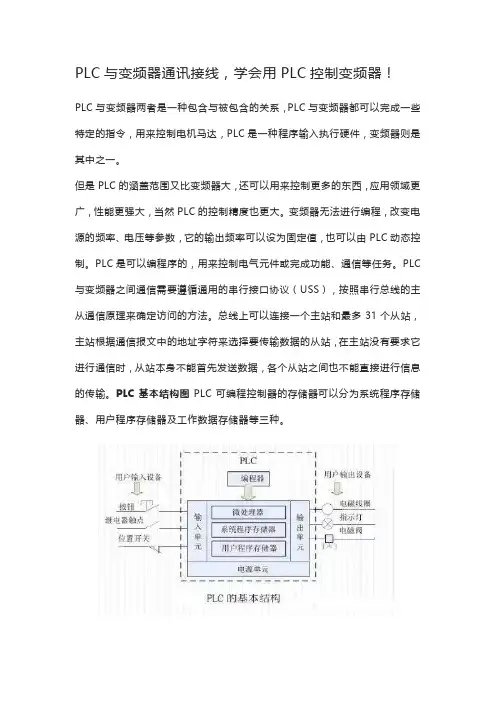
PLC基本结构图PLC可编程控制器的存储器可以分为系统程序存储器、用户程序存储器及工作数据存储器等三种。
1、系统程序存储器系统程序存储器用来存放由可编程控制器生产厂家编写的系统程序,并固化在ROM内,用户不能直接更改。
系统程序质量的好坏,很大程度上决定了PLC的性能。
其内容主要包括三部分:第一部分为系统管理程序,它主要控制可编程控制器的运行,使整个可编程控制器按部就班地工作,第二部分为用户指令解释程序,通过用户指令解释程序,将可编程控制器的编程语言变为机器语言指令,再由CPU执行这些指令;第三部分为标准程序模块与系统调用程序。
2、用户程序存储器根据控制要求而编制的应用程序称为用户程序。
用户程序存储器用来存放用户针对具体控制任务,用规定的可编程控制器编程语言编写的各种用户程序。
目前较先进的可编程控制器采用可随时读写的快闪存储器作为用户程序存储器,快闪存储器不需后备电池,掉电视数据也不会丢失。
3、工作数据存储器工作数据存储器用来存储工作数据,既用户程序中使用的ON/OFF状态、数值数据等。


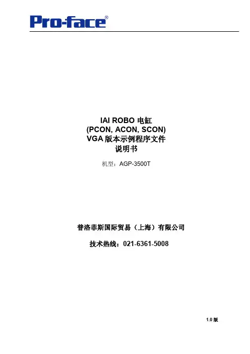
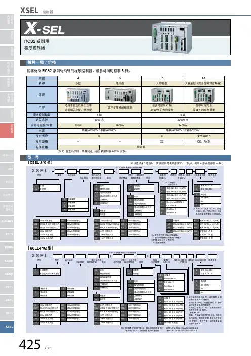
IAI ROBO 电缸(PCON, ACON, SCON)VGA版本示例程序文件说明书机型:AGP-3500T普洛菲斯国际贸易(上海)有限公司技术热线:021-6361-50081.0 版目录内容页码1. 设备组态 (3)1.1 设备连接 (3)1.2 ROBO电缸:连接单台设备(RS-232C) (4)1.3 ROBO电缸:连接多台设备 (RS-422/485) (5)2. 通讯设置 (10)2.1 从[系统设置]窗口中点击[控制器/PLC],显示设置画面 (10)2.2 ROBO 电缸 (13)3. 画面 (16)3.1 菜单画面 (16)3.2 历史报警代码/描述画面 (17)3.3 监控器/操作画面 (18)3.4 坐标表画面 (20)3.5 输入/输出端监控画面 (22)3.6 参数设置画面 (23)4. 地址 (24)* IAI ROBO 电缸设置更详细描述,请参照IAI公司操作手册;* 以上文件可以直接从IAI公司主页下载;注意:在您的系统中使用本例时,请在操作前检查。
1. 设备组态1.1 设备连接Pro-face 人机界面IAI ROBO 电缸(*1)本案例参考1:1连接(RS-232C)的系统组态;人机界面RS-232C/485放大器ROBO 电缸1.2 ROBO电缸:连接单台设备(RS-232C)注意:RS-232转换模块(RCB-CV-MW)和通讯电缆(CB-RCA-SIO050)都是由IAI制造的PC人机软件(RCM-101-MW)的附件;1.除AGP-3302B以外的所有GP机型。
2.当使用多于一套AMP接头,需要自制电缆2。
3.除GP3200系列和AGP-3302B以外的所有GP机型。
A) 当使用由Pro-face制造的串口转换适配器(CA3-ADPCOM-01)和RS-422转换适配器(CA3-ADPTRM-01)和自制电缆1,以及IAI制造的AMP接头和放大器连接电缆(CB-RCB-CTL002);B) 当使用自备电缆1,IAI制造的AMP接头(5-1473574-4)和放大器连接电缆(CB-RCB-CTL002);C) 当使用Pro-face制造的串口通讯终端适配器(CA4-ADPONL-01)和RS-422转换适配器 (CA3-ADPTRM-01),自制电缆1,IAI制造的AMP接头(5-1473574-4)和放大器连接电缆(CB-RCB-CTL002);D) 当使用Pro-face制造的串口通讯终端适配器(CA4-ADPONL-01),自制电缆1,IAI制造的AMP接头(5-1473574-4)和放大器连接电缆(CB-RCB-CTL002);2. 通讯设置2.1 从[系统设置]窗口中点击[控制器/PLC],显示设置画面<RS-232C>GP 设置SIO Type RS232C Speed 38400 Data Length 8 Parity NONE Stop Bit 1Flow Control NONE个别控制器设置Axis No. 0<RS-422/485>►重点通讯设置的信息和电缆制作图,请参照GP-Pro EX 中自带的控制器/PLC连接手册“IAI公司ROBO CYLINDER MODBUS SIO驱动”;安装GP-Pro EX软件时,控制器/PLC连接手册也一同安装;*1您可以通过以下方式查看手册。


ROBONET使用方法(CC-Link通訊)飛泰貿易有限公司何雲遠(社內秘)安裝方法:預備各RoboNet單元,Dim安裝軌,左右頂塊(Dim安裝軌及左右頂塊需客戶自備把RoboNet單元上固定架拉後,將RoboNet單元安裝於Dim安裝軌,把RoboNet單元上固定架前推,將RoboNet單元固定於Dim安裝軌,將所有RoboNet單元安裝於Dim安裝軌,把左右頂塊固定於Dim安裝軌把控制器通訊連接電路板安裝於各RoboNet 單元,並安裝終端抵抗電路板於最後一單元(請確定安裝及拔出控制器通訊連接電路板及終端抵抗電路板時電源必須關閉)DC24V 0V打開各單元上蓋把電源連接板安裝於各RoboNet 單元,導通各單元間電源接上電源線DC24V0V急停輸入端子插口接地線端子插上急停輸入端子及接上地線如使用簡單絕對單元,對應 軸的編碼器電纜連接於該簡易絕對單元馬達電纜馬達電纜編碼器電纜編碼器電纜接上各驅動軸的馬達電纜 及編碼器電纜至各對應RoboNet 單元對主局及最後的子局,DA 及DB 需連接上110Ω1/2W 電阻(黃)(白)(藍)(黃)(白)(藍)(黃)(白)(藍)(黃)(白)(藍)子局1子局2主局以CC-Link 電纜連接主局PLC 的CC-Link 模塊110Ω1/2W 電阻110Ω1/2W 電阻RoboNet CC-Link通訊設定:請於以下網址下載Parameter Configuration Tool for IAI ROBONETGateway Unit並安裝於電腦/software.php按下此處下載,儲存或直接安裝以CB—CV-MW及CB—RCA-SIO050或CB-SEL-USB010,RCB-CV-USB及CB- RCA-SIO050 連接電腦及RoboNet CC-Link 通訊單元(RGW-CC), 執行Parameter Configuration Tool for IAI ROBONET Gateway Unit軟件,選擇通訊口號碼及通訊速率(一般選擇38400),按”OK”鍵按:”Read”,讀取RoboNet內設定客戶可根據CC-Link 網絡,設定RoboNet 單元地址對應主局的CC-Link 的通訊速率設定淮許功能,可選擇”Shutdown”或“ServoOff”選擇簡易直值模式或定位模式軸數選擇直接數值指定模式軸數對應軸選擇簡易直值模式時,按下此位置,出現*對應軸選擇定位模式時,按下此位置,出現*定位模式簡易直值模式直接數值指定模式位置數768點768點╳位置號指定移動○╳╳位置座標指定移動╳○○速度,加速度直接指定╳(根據位置號內數據)╳(根據位置號內數據)○定位距離直接指定╳(根據位置號內數據)╳(根據位置號內數據)○推壓動作╳(根據位置號內數據)╳(根據位置號內數據)○(可直接指定推壓電流)動作完了位置號輸出○○╳區位輸出○○○位置號區位輸出○○╳教導功能○╳╳JOG動作○○○寸進動作○○○軸狀態信號輸出○○○現在位置值輸出○○○錯誤碼輸出○○○速度,電流值輸出╳╳○位置數值指定最大值9999.99mm9999.99mm9999.99mm最大連接軸數16168定位模式■只是單純使用定位,還沒能力做到隨意定位例・使用多台PCON、ACON・偶爾需要在觸幕屏上變更位置數據・512個位置點數不够,最好有768個。
Caution: Make sure to turn the power to the controller OFF when inserting or removing the connector that connects the PC software or teaching pendant to the controller.(For touch panel teaching (CON-PTA, TB-01), insertion and removal of the active line is available.)Inserting or removing the connector while the power is turned ON causes a controller failure.在断开电脑或示教器与控制器的连接时,请将电断掉。
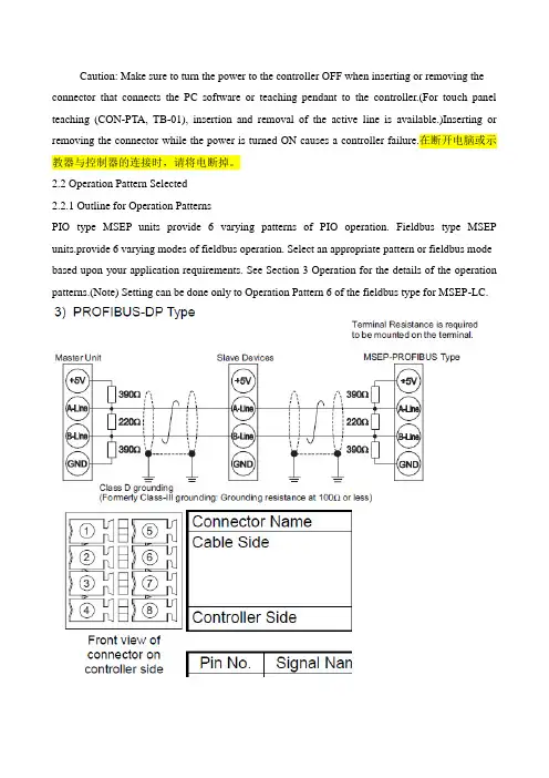
2.2 Operation Pattern Selected2.2.1 Outline for Operation PatternsPIO type MSEP units provide 6 varying patterns of PIO operation. Fieldbus type MSEP units.provide 6 varying modes of fieldbus operation. Select an appropriate pattern or fieldbus mode based upon your application requirements. See Section 3 Operation for the details of the operation patterns.(Note) Setting can be done only to Operation Pattern 6 of the fieldbus type for MSEP-LC.看到第37页第83页:Operation of MSEP-C(Note) Refer to 3.2 for MPEP-LC Type 3.1.1 Basic Operation MethodsThere are two types of methods for operation, one to control with PIO and the other to controlwit fieldbus. Check the model code indicated on the model code card attached on the frontpanel of the body to see which method should be applied for your product. [Refer to Section1.1.5]Operation Mode Available in Fieldbus Type。
自动化控制 • Automatic Control118 •电子技术与软件工程 Electronic Technology & Software Engineering 【关键词】西门子 PLC 施耐德 ATV71/61变频器 Profibus-DP 通信随着信息技术的不断发展,大型企业均采用全数字集成控制,主要通过主控计算机对数据进行收集以及运算。
Profibus-DP 是一个性能较强的高速现场总线,具有读取主站信息的功能,并能够将主站周期的信息向从站发送。
主要有两种介质访问模式,第1种为分散模式,该模式主要采用令牌传递原理,第2种为集中方式,该模式主要采用主从通信原理,连接方式主要采用双线电缆或光缆,RS-485双绞线进行连接,拓扑结构可为多种形状,例如,环形,星星或树型。
1 西门子P L C 与A T V 71/61变频器的Profibus-DP连接主要采用集中介质访问模式,常用的拓扑结构为树形结构,下文主要应用此类型进行叙述。
1.1 通信卡接头管脚结构及相关定义想要实现ATV71/61变频器与Profibus-DP 网络的连接,VW3A3307通行卡是必不可少的条件,应保证Profibus-DP 通信卡具有9针SUB-D 连接器,同时,不需要任何额外的设备相连接,使用标准的Profibus-DP 电缆及接头进行连接即可。
1.2 通信卡的设置通讯卡在设置过程中,需要设置从站地址。
设置完成后,通过拨动拨码开关,完成开关设置,向上波动为ON ,向下拨动为OFF 。
开关组通常以二进制代码向十进制转换,即可设置从站地址,地址为23的拨码为00010111,第1支为89的拨码对应为01011001,寻址开关放置到ON 上就可以与ATV71/61系列变频器连接,拨到OFF 处能够西门子PLC 与施耐德ATV71/61变频器的Profibus-DP 通信文/盛丽娜变频器的启动、停止,频率设定等通信离不开PLC 和变频的支持,可实现多电机之间的同步运行,具有传输距离远,成本低,抗干扰能力强的特点。
Programmable control systems PSS®All rights to this documentation are reserved by Pilz GmbH & Co. KG. Copies may be made for internal purposes.Suggestions and comments for improving this documentation will be gratefully received.Pilz®, PIT®, PMI®, PNOZ®, Primo®, PSEN®, PSS®, PVIS®, SafetyBUS p®, SafetyEYE®, SafetyNET p®, the spirit of safety® are registered and protected trademarks ofPilz GmbH & Co. KG in some countries.ContentsApplication in Accordance with the Regulations1-1 Safety Regulations1-1PROFIBUS Wiring1-1Installation1-3Operation2-1LEDs2-1Plug-in Connector2-1Setting the Station Address2-2Appendix3-1Connector Pin Assignment3-1Order References3-1Technical Details3-2IntroductionThis manual describes the hardware of the PROFIBUS-DP-Slave Module.A separate manual, "PROFIBUS-DP-SLAVE" deals with the configurationand programming of the module and is included with the PROFIBUS FBsoftware package (Order No. 301 259).This manual is divided into the following chapters:1)Application in accordance with safety regulationsDescribes the application areas for the module and providesinformation on safety measures to be adopted both during installationand operation.2)OperationExplains the functions of the control devices on the front of themodule.3)AppendixContains the technical details and interface configuration.WARNING!Please read chapter 1 before using the module!IntroductionApplication in Accordance with the RegulationsThis module is a passive subscriber (Slave) of PROFIBUS-DP. It meetsthe requirements of the standard: EN 50 170 Volume 2, PROFIBUS.The PSS DP-S module may only be used on the standard bus of thePSS 3000.The PSS1 DP-S module may only be used on the standard bus of thePSS 3100.The module is designed for use in an industrial environment. Problems ofinterference could occur if used within a domestic environment.Safety Regulations•Please read the “Installation Manual” of the relevant safetycontroller before installing and commissioning the module.•The guarantee will be rendered invalid if the unit is opened or if anychanges are made to the printed circuit boards, such as exchanging acomponent or carrying out soldering work. Units requiring repair must bereturned to Pilz.•Remember to keep as large a distance as possible between the safetycontroller and any electromagnetic fields, particularly when frequencyconverters are nearby. Where necessary, use suitable screening toseparate the safety controller from the source of interference. PROFIBUS WiringThe screened cable should be earthed at the connector or at the point atwhich it enters the control cabinet!Transmission CableThe maximum length of the transmission cable is dependent on the baudrate. The standard recommends Type A cables (see below). Type Bcables can only use shorter cable runs and lower baud rates.The following cable runs are permitted, depending on the baud rate:Baud rate (kbit/s) 9.6/19.2/93.75187.55001,5003,000/6,000/12,000Length (m) Type A12001000400200100Length (m) Type B1200600200--Application in Accordance with the RegulationsRequirements:ParametersType A cable Type B cable Capacitor<30 pF/m <60 pF/m Loop Resistance<110 Ohm/km -Wire Diameter>0.64 mm >0.53 mm Wire Cross-section>0.34 mm 2>0.22 mm 2Impedance Level 135 ... 165 Ohm100 ... 130 Ohm (3 .... 20 MHz)(>100 kHz)Do not use stub lines to connect subscribers (Fig. 1)!See Fig. 2 for a diagram showing the correct connection.In practise, each subscriber connection represents a stub line (cable from the branching in the connector to the cable transceiver on the module, in the magnitude 20 to 50 mm). This means that practically no stub lines are permitted with faster baud rates.Example: With a baud rate of 1500 kBit/s the capacitance of all the stub lines must be less than 0.2 nF. With Type A cable this gives a maximum length of 6.6 m for all the stub lines. With 12 MBits/s, only 1.6 m arepermitted, which means that, with 32 subscribers, the limit would be 50 mm each.With faster baud rates, therefore, you should use connectors with inline inductors. The inductors relate to a connected subscriber. Ifconnectors are removed, mismatches occur which may lead to problems.Please refer to the installation guidelines in the manual for the Master unit and the advice given in the standard, as well as advice issued bythe PROFIBUS User Organisation (PNO).Application in Accordance with the RegulationsConnectors on the first and last subscribers should be fitted with terminating resistors.Various companies (Siemens, Erni,...) have designed special connectors which incorporate both the terminating resistor (may be switchable) and the inductors for impedance matching.Examples:Siemens:GES7 972-0BA20-0XA0Erni:ERbic 104.050Deltron:DE 004830InstallationThe module should be installed as described in the “PSS 3000/PSS 3100Installation Manual”.Application in Accordance with the RegulationsOperationThis chapter explains the functions of the control devices on the front ofthe module. The module's operation as a subscriber on PROFIBUS isdescribed in the “PROFIBUS-DP-Slave Software” Manual.LEDsThe LEDs “RUN” and “FAULT” display the module's operating status.Plug-in ConnectorThe interface to PROFIBUS-DP is on the front of the module. The layoutof the 9-pin plug connector is described in the Appendix.OperationSetting the Station AddressThe station address is set using one slide switch and two rotary switches.Permitted values are: 0 ... 126 decimal.Setting Addresses 0 . (99)In the above drawing, address 64 is set as an example.Setting Addresses 100 (126)In the above drawing, address 114 is set as an example.AppendixConnector Pin AssignmentPROFIBUS is connected via a 9-pin D-Sub-connector.AppendixTechnical Details•• …• www+49 711 3409-44419 452, 2008-02 P r i n t e d i n G e r m a n y © P i l z G m b H & C o. K G , 2008Pilz GmbH & Co. KG Sichere Automation Felix-Wankel-Straße 273760 Ostfi ldern, Germany Telephone: +49 711 3409-0Technical supportIn many countries we arerepresented by sales partners.Please refer to our homepage for further details or contact our headquarters.。
PROFIBUS-DP主站转ETHERCA T网关连接汇川ethercat通讯协议PROFIBUS-DP主站转ETHERCA T网关连接ethercat网线接口定义PROFIBUS-DP主站转ETHERCA T网关profibus和modbus区别PROFIBUS-DP主站转ETHERCA T网关profibus协议是什么PROFIBUS-DP主站转ETHERCA T网关连接ethercat通讯过程描述PROFIBUS-DP主站转ETHERCA T网关连接ethercat通讯协议详细解析PROFIBUS-DP主站转ETHERCA T网关连接ethercat转换器PROFIBUS-DP主站转ETHERCA T网关连接ethercat总线控制PROFIBUS-DP主站转ETHERCA T网关连接canopen协议报文解析实例PROFIBUS-DP主站转ETHERCA T网关连接到300plc的配置方法PROFIBUS-DP主站转ETHERCA T网关连接支持ethercat总线的PLCPROFIBUS-DP主站转ETHERCA T网关连接ethercat总线伺服如何控制PROFIBUS-DP主站转ETHERCA T网关连接安川ethercat总线伺服PROFIBUS-DP主站转ETHERCA T网关连接安川伺服支持EtherCA T总线吗PROFIBUS-DP主站转ETHERCA T网关连接西门子支持ethercat吗大家好,今天要给大家介绍一款远创智控的神秘产品,它的名字叫YC-DPM-ECT,是一款兼具PROFIBUS-DP主站功能的通讯网关。
想象一下,它既能和PROFIBUS总线打交道,又能与ETHERCAT网络愉快地交流,是不是感觉很神奇?别看这只是一台小小的网关,它的作用可是非常大的!它可以将各种PROFIBUS-DP从站接入到ETHERCAT网络中,让它们在我们的数字世界中自由交流。
这就像是数字世界的“翻译官”,让我们能够听懂各种不同的语言。
1.前言打招呼由我和我為你服務多謝您購買本公司產品。
SA系列產品使用容易.體積小,可以自在控制傳動裝置與週邊設備。
除此之外,使用SEL語言還可實現簡單的高度控制夢想。
請仔細詳讀『操作說明書』。
2.安全上的應注意事項請詳讀下列內容,充分留意安全對策。
本產品以自動化機械等的驅動零組件開發而成,因此在自動化機器驅動源的轉矩或速度方面,有請勿超乎標準以外的限制。
為了防止發生事故,請嚴守下列事項。
並請務必參照「安全規則」。
1.本書沒有記載的操作方法,原則上請以「不可操作」解釋。
對於本書內容如有不明之處,請與本公司聯絡。
2.傳動裝置與控制器之間的配線,請務必使用指定之正品。
3.當機械在運動狀態,或者可運動狀態(打開控制器電源狀態)時,請勿站立在機械的運動範圍。
另外也請在周圍設置柵欄,以防止外人接近機械。
4.執行機械之安裝調整作業,或者維修檢查作業時,請務必關閉控制器電源。
並請將「作業中」銘板放置在明顯的場所。
另外,請勿纏繞電線,也避免插入來路不明的電源插座裡。
5.當複數人同時作業時,必須採取一個對應方法,以確認彼此安全作業。
特別是不論開.關電源,或驅動.手動馬達等移動軸的作業,都必須發出聲音確定安全後再進行作業。
6.當使用者(客戶)需要延長配線時,因錯誤配線有可能會導致錯誤動作,因此請充分檢查配線後,並確認正確配線方式後再打開電源。
附錄「安全規則」關於產業用自動裝置安全的JIS規格----「產業用自動裝置之安全通則」(JIS B8433)於1983年3月1日制定,另外由勞動省於同年7月1日修改一部分的「勞動安全衛生規則」,以實施產業用自動裝置之定義或,安全對策等規則。
在此所介紹的是,參考「勞動安全衛生規則」之產業用自動裝置安全對策上的重要規則。
●特別教育(第36條第31號,第32號)第36條第31號操縱裝置及記憶裝置(包含可變序列控制裝置及固定序列控制裝置。
),以記憶裝置資訊為基礎之操縱裝置之伸縮.屈伸.上下移動.左右移動,或者旋轉動作或複合動作等,均可自動執行之機械(除了研究開發中之其他勞動大臣所制定之裝置以外。
SMC电缸MODBUS通讯控制SCL代码//============================================== =============================================== ==============================//1、上升沿信号 R_TRIGIF #V.Output.位状态.X_电缸使能AND NOT #V.Output.X_通讯错误THEN#R_TRIG[0](CLK := #V.input.X_电缸动作AND NOT #电缸Output读取.位状态.X_运行中AND #IN号= #V.input.X_IN 号);#R_TRIG[1](CLK := #V.input.X_故障清除AND NOT #电缸Output读取.位状态.X_运行中);#R_TRIG[2](CLK := #V.input.X_回原点AND NOT #电缸Output读取.位状态.X_运行中);#R_TRIG[4](CLK := #V.input.X_通讯重启AND NOT #电缸Output读取.位状态.X_运行中);#R_TRIG[5](CLK := #V.input.X_电缸动作);END_IF;//--------------------------------------------------------------------------------------------------------------------------//2、通讯参数设置IF #FirstScan OR (#R_TRIG[4].Q AND #V.Output.X_通讯错误) THEN#Modbus_Comm_Load.MODE := 4;#Modbus_Comm_Load.REQ := 1;#V.Output.X_通讯错误:= 0;#i := 0;END_IF;#Modbus_Comm_Load("PORT" := #PORT,BAUD := 38400,RESP_TO := 1000,MB_DB := #Modbus_Master主站.MB_DB); //3、通讯启动IF NOT #V.Output.X_通讯错误AND#Modbus_Comm_Load.DONE OR (#TON_TIME.Q AND NOT #Modbus_Master主站.BUSY) THEN#Modbus_Master主站.REQ := TRUE;#启动延时:= FALSE;IF #Modbus_Comm_Load.REQ = 1 THEN#Modbus_Comm_Load.REQ := 0;END_IF;END_IF;//--------------------------------------------------------------------------------------------------------------------------//4、MODBUS通讯主站参数地址#Modbus_Master主站.MB_ADDR := #Request[#i].站号;#Modbus_Master主站.MODE := #Request[#i].方式;#Modbus_Master主站.DATA_ADDR := #Request[#i].地址;#Modbus_Master主站.DATA_LEN := #Request[#i].长度;#Modbus_Master主站(DATA_PTR := #Request[#i].传送数据); IF #Modbus_Master主站.ERROR THEN#V.Output.X_通讯错误代码:= #Modbus_Master主站.STATUS;#V.Output.X_通讯错误:= TRUE;#V.InOut.动作号:= 0;END_IF;//通讯结束后延时时间30ms启动下次轮询#TON_TIME(IN := #启动延时,PT := t#30ms);//============================================== =============================================== ====================================FOR #A := 0 TO 2 DO//判断X_电缸动作、X_故障清除、X_回原点上沿条件IF #R_TRIG[#A].Q THEN#V.InOut.动作号:= 500;#Request[5].传送数据[#A] := 1;EXIT;END_IF;END_FOR;//----------------------------------------------------------------------------------------------------------------------------------IF #R_TRIG[5].Q THEN#电缸Output读取.位状态.X_动作到位:= 0;END_IF;//IN号判读IF #IN号<> #V.input.X_IN号AND NOT #电缸Output读取.位状态.X_运行中AND #V.InOut.动作号>0 THEN#V.InOut.动作号:= 400;END_IF;//5、动作流程树IF #Modbus_Master主站.DONE THEN#Modbus_Master主站.REQ := FALSE;#启动延时:= 1;//-----------------------------------------------------------------------------------------------------------------------//#i:= 值代表含义//0 开启电缸通讯的地址写入地址位//1 电缸使能通讯地址//2 电缸位状态读取//3 电缸字状态读取//4 IN号修改写入//5 X_电缸动作、X_故障清除、X_回原点状态条件写入//------------------------------------------------------------------------------------------------------------------------IF NOT #V.input.X_模式选择AND NOT #电缸Output读取.位状态.X_运行中THEN//电缸动作相应参数设置判断FOR #B := 0 TO 3 DOIF "电缸Static".参数待写区[#B] <> #电缸参数[#B] THEN"电缸Static".参数待写区[#B] := #电缸参数[#B];FOR #A := 0 TO 31 DOPOKE(area := 16#84,dbNumber := #DB地址,byteOffset := 2692 + (#B * 42) + #A,value := PEEK(area := 16#84, dbNumber := 7, byteOffset := 0 + (#B * 32) + #A));END_FOR;#i := 6 + #B;#V.InOut.动作号:= 100;EXIT;ELSEIF #V.InOut.动作号= 100 THEN#V.InOut.动作号:= 200;#i := 2;END_IF;END_IF;END_FOR;END_IF;//------------------------------------------------------------------------------------------------------------------------CASE #V.InOut.动作号OF0:IF #i = 0 THEN//开启电缸通讯的地址写入地址位#i := 1;ELSIF #i = 1 THEN//电缸使能通讯地址#i := 2;#V.InOut.动作号:= 200;END_IF;200://电缸位状态读取FOR #B := 0 TO 1 DOPOKE(area := 16#84,dbNumber := #DB地址,byteOffset := 2414 + #B,value := PEEK(area := 16#84, dbNumber := #DB地址, byteOffset := 2524 + #B));END_FOR;#V.InOut.动作号:= 300;#i := 3;300://电缸字状态读取FOR #B := 0 TO 14 DOPOKE(area := 16#84,dbNumber := #DB地址,byteOffset := 2416 + #B,value := PEEK(area := 16#84, dbNumber := #DB地址, byteOffset := 2566 + #B));END_FOR;#V.InOut.动作号:= 200;#i := 2;400://IN位修改参数写入#IN号:= #V.input.X_IN号;POKE(area := 16#84,dbNumber := #DB地址,byteOffset := 2608,value := PEEK(area := 16#84, dbNumber :=#DB地址, byteOffset := 2412));#i := 4;#V.InOut.动作号:= 410;410://IN写入后判断是否连续动作IF NOT #V.input.X_电缸动作THEN#V.InOut.动作号:= 200;#i := 2;END_IF;500:// X_电缸动作、X_故障清除、X_回原点状态条件写入#i := 5;#V.InOut.动作号:= 510;510:// X_电缸动作、X_故障清除、X_回原点状态条件判断若有处于开启状态进行复位IF #Request[5].传送数据[0] OR #Request[5].传送数据[1] OR #Request[5].传送数据[2] THEN#Request[5].传送数据[0] := FALSE;#Request[5].传送数据[1] := FALSE;#Request[5].传送数据[2] := FALSE;ELSE#i := 2;#V.InOut.动作号:= 200;END_IF;END_CASE;END_IF;//电缸状态读取后输出#V.Output.位状态:= #电缸Output读取.位状态; #V.Output.字状态:= #电缸Output读取.字状态;。
PLC控制电缸“万能模板”-建议收藏
电缸的控制方法不胜枚举,本文介绍一下如何用三菱PLC,通过CCLINK方式控制IAI电缸。
电缸控制系统构成图
1.设置参数
参数设置包含:PLC侧和电缸控制器侧。
①.PLC侧参数设置
设置好CCLINK站号,站类型“远程设备站”、占用站数根据实际情况选择,一般是4站。
CCLINK参数设置
②.电缸控制器参数设置
No.84现场网络动作模式:3
No.85现场网络节点(站号)地址: CC-Link站号分配
No.86现场网络通信速度:和CC-Link IO模块波特率一致
No.87网络类型:1
必须先设电缸的站号,不然默认为第1站,CCLINK的IO模块连接不上。
参数设置好后就可以通讯测试了。
2.信号分配
①地址分配
地址分配表
②.控制信号分配
控制信号分配③.状态信号分配
状态信号分配3.PLC程序编写
控制参数程序
控制信号程序
自动定位启动程序
4.人机界面程序编写
人机界面程序包含:
①.操作区:伺服上电、JOG、停止、报警复位等。
②.参数设定区:定位位置参数、误差范围、定位速度等。
③.参数反馈区:当前位置、目标位置、当前速度、报警代码等。
人机界面画面
5.试运行
以上步骤全部完成后,就可以开始试运行程序了。
以下来自MJ0258手册,对PCON-CA的PROFIBUS-DP通讯的操作说明:Operation Modes and FunctionsPCON-CA/CFA controllers supporting PROFIBUS-DP can be operated in a desired operation mode selected from the following five modes.Operation Modes and Key Functions[3] Half direct mode: In this mode, the actuator is operated by specifying the speed,acceleration/deceleration and push current, in addition to the target position, directly as values. Number of occupied bytes: 16 bytes (8 words)[4] Full direct mode: In this mode, the actuator is operated by specifying all values relating to position control(target position, speed, acceleration/deceleration, etc.) directly as values.Number of occupied bytes: 32 bytes (16 words)4.3 PROFIBUS-DP (Slave Station) Settings(1) Name of each partThe name of each part relating to PROFIBUS-DP is shown.(4) Operation mode selection (setting) 第95页Set a desired operation mode using a parameter.Set the mode selector switch on the front side of the controller to the MANU position, and then set parameter No.84, “FMOD: Fieldbus operation mode” using the RC PC software (V6.00.05.00 or later). (Refer to 4.7,“PROFIBUS-DP.”)Note Refer to operation manual of RC PC Software for the applicable version.(5) Node address setting (Refer to 4.7)Set the node address using a parameter.Set parameter No. 85, “NADR: Fieldbus node address” using the RC PC software.(Refer to 4.7, “PROFIBUS-DP Parameters.”) Settable range: 0 to 125 (The parameter has been set to 1 at the factory.)(Note 1) Pay attention to duplicate node address settings.(Note 2) PROFIBUS-DP node addresses are set with the master station always having address 0. Accordingly,addresses of slave stations can be set between 1 and 125.(6) Status LED indicationsThe board operating condition and network condition can be checked using the two LEDs provided on the front side of the controller.(Note 1) After the necessary parameters have been set, reconnect the controller power and return the mode selector switch on the front side of the controller to the AUTO position. If the switch remains in the MANU position, PLC operation cannot be performed.(Note 2) 有关波特率的设置The baud rate is automatically set according to the corresponding setting on the master side and thus need not be set.The address assignments under each operation mode are shown below.PLC output →PCON-CA/CFA input (* n indicates the initial output address for each axis.)(Note) The “occupied area” is occupied according to the operation mode setting.This area cannot be used for any other purpose. Also pay attention to use of duplicate addresses.PCON-CA/CFA output →PLC input (* n indicates the initial input address for each axis.)(Note) The “occupied area” is occupied according to the operation mode setting.This area cannot be used for any other purpose. Also pay attention to use of duplicate addresses.4.4.4 Half Direct Mode (Number of Occupied Bytes: 16)第109页In this mode, the actuator is operated by specifying the target position, positioning band, speed, acceleration/deceleration and push current directly as values from the PLC.Set each value in an applicable I/O address. If the zone function is used, set parameter Nos. 1, 2, 23 and/or 24.The key functions that are available on ROBO Cylinders controllable in this mode are shown in the tablebelow.(1) PLC address configuration (* n indicates the initial input/output address for each axis.)第109页(Note) Pay attention to use of duplicate addresses.(2) I/O signal assignments for each axis第110页An I/O signal of each axis consists of 8 words (16 bytes) of I/O addresses.①Control signals and status signals are bit ON/OFF signals.②The target position and current position are both a 2-word (32-bit) binary data. Although values from -999999 to +999999 (unit: 0.01 mm) can be handled by the PLC, set position data within the software stroke range (0 up to the effective stroke length) of the applicable actuator.③Set a desired positioning band. The positioning band is a 2-word (32-bit) binary data and values from 1 to +999999 (unit: 0.01 mm) can be handled by the PLC.④The speed is a 1-word (16-bit) binary data. Although values from 0 to +65535 (unit: 1.0 mm/sec or 0.1mm/sec)can be handled by the PLC, set a value not exceeding the maximum speed of the applicable actuator.The setting of unit can be established in Parameter No. 159 FB Half Direct Mode Speed Unit.⑤The acceleration/deceleration is a 1-word (16-bit) binary data. For the acceleration/deceleration, the PLC can handle values from 1 to 300 (unit: 0.01 G). Take note, however, that the set value should not exceed the maximum acceleration or maximum deceleration supported by the applicable actuator.⑥The push-motion current-limiting value is a 1-word (16-bit) binary data. For the push-motion current-limiting value, the PLC can handle values from 0 (0%) to 255 (100%). Take note, however, that the setting should be inside the allowable specification range of push-motion current-limiting values supported by the applicable actuator (refer to the catalog or operation manual for the actuator).⑦The command current is a 2-word (32-bit) binary data (unit: 1 mA).⑧The current position is a 2-word (32-bit) binary data (unit: 0.01 mm/sec).Positive value: The actuator is moving in the direction opposite home. / Negative value: The actuator is moving in the direction of home.这个解释应该有问题,单位是有问题的,也有可能解释的是速度。