5.外文原文
- 格式:pdf
- 大小:434.39 KB
- 文档页数:24

73rd Annual Meeting of ICOLDTehran, IRANMay 1- 6, 2005Paper No.: 012-W4 REVIEW OF SEISMIC DESIGN CRITERIA OF LARGE CONCRETEAND EMBANKMENT DAMSMartin WielandChairman, ICOLD Committee on Seismic Aspects of Dam Design, c/o Electrowatt-Ekono Ltd. (Jaakko Pöyry Group),Hardturmstrasse 161, CH-8037 Zurich, SwitzerlandABSTRACTOf all the actions that dams have to resist from the natural and man-made environment, earthquakes pose probably the greatest challenge to dam engineers as earthquake ground shaking affects all structures (dam body, grout curtains, diaphragm walls, underground structures and different appurtenant structures) and all components (hydromechanical, electromechanical, etc.) at the same time (ICOLD, 2001; ICOLD, 2002). Thus all these elements have to be able to resist some degree of earthquake action. This also applies to temporary structures like cofferdams, etc. For the specification of the degree of earthquake action these components have to be able to resist an assessment of the consequences of possible failure scenarios is needed.Little experience exists about the seismic performance of modern concrete-face rockfill dams, which are being built in increasing number today. A qualitative assessment of these dams is given.Keywords: concrete dams, embankment dams, concrete-face rockfill dams, CFRD, grout curtain, earthquake design criteria for damsINTRODUCTIONSince the 1971 San Fernando earthquake in California, major progress has been achieved in the understanding of earthquake action on concrete dams. The progress was mainly due to the development of computer programs for the dynamic analysis of dams. However, it is still not possible to reliably predict the behaviour of dams during very strong ground shaking due to the difficulty in modelling joint opening and the crack formation in the dam body, the nonlinear behaviour of the foundation, the insufficient information on the spatial variation of ground motion in arch dams and other factors. The same applies to embankment dams where the results of inelastic dynamic analyses performed by different computer programs tend to differ even more than in the case of concrete dams. Also, considerable progress has been made in the definition of seismic input, which is one of the main uncertainties in the seismic design and seismic safety evaluation of dams.It has been recognized that during strong earthquakes such as the maximum credible earthquake (MCE), the maximum design earthquake (MDE) or the safety evaluation earthquake (SEE) ground motions can occur, which exceed those used for the design of large dams in the past. Already a moderate shallow-focus earthquake with a magnitude of say 5.5 to 6 can cause peak ground accelerations (PGA) of 0.5 g. However, the duration of strong ground shaking of such events is quite short and the predominant frequencies of the acceleration time history are also rather high. Therefore, smaller concrete dams may be morevulnerable to such actions than high dams, which have predominant eigenfrequencies that are smaller than those of such ground acceleration records.We have to recognize that most of the existing dams have been designed against earthquake actions using the pseudostatic approach with an acceleration of 0.1 g. In regions of high seismicity like Iran the PGA of the SEE may exceed 0.5 g at many dam sites. Therefore, some damage may have to be expected in concrete dams designed by a pseudostatic method with a seismic coefficient of 0.1.Because of the large differences between the design acceleration and the PGA, and because of the uncertainties in estimating the ground motion of very strong earthquakes at a dam site, mechanisms are needed that ensure that a dam will not fail if the design acceleration is exceeded substantially.In the case of large dams, ICOLD recommends to use the MCE as the basis for the dam safety checks and dam design. Theoretically no ground motion should occur, which exceeds that of the MCE. However, in view of the difficulties in estimating the ground motion at a dam site, it is still possible that larger ground motions may occur. Some 50 years ago, many structural engineers considered a value of ca. 0.2 g as the upper bound of the PGA, but today with more earthquake records available, the upper bound has exceeded 1 g and some important structures have already been checked against such high ground accelerations.1. SEISMIC DESIGN CRITERIA FOR LARGE DAM PROJECTSAccording to ICOLD Bulletin 72 (1989), large dams have to be able to withstand the effects of the MCE. This is the strongest earthquake that could occur in the region of a dam, and is considered to have a return period of several thousand years (typically 10’000 years in regions of low to moderate seismicity).Per definition, the MCE is the largest event that can be expected to affect the dam. This event can be very powerful and can happen close to the dam. The designer must take into account the motions resulting from any earthquake at any distance from the dam site, and possible movement of the foundation if a potentially active fault crosses the dam site. Having an active fault in the foundation is sometimes unavoidable, especially in highly seismically active regions, and should be considered as one of the most severe design challenges requiring special attention.It has to be kept in mind that each dam is a prototype structure and that the experience gained from the seismic behaviour of other dams has limited value, therefore, observations have to be combined with sophisticated analyses, which should reflect reality as close as possible.We also have to realize that earthquake engineering is a relatively young discipline with plenty of unsolved problems. Therefore, every time there is another strong earthquake some new unexpected phenomena are likely to emerge, which have implications on regulations and codes. This is particularly true for dams as very few modern dams have actually been exposed to very strong ground motions.As mentioned earlier, the time of the pseudostatic design with a seismic coefficient of 0.1 has long passed. Of course, this concept was very much liked by designers because the small seismic coefficients being used did not require any special analyses and the seismic requirement could easily be satisfied. As a result, the seismic load case was usually not the governing one. This situation has changed and the earthquake load case has become the governing one for the design for most high risk (dam) projects, especially in regions of moderate to high seismicity.As a general guideline, the following minimum seismic requirements should be observed:(i)Dam and safety-relevant elements: Design earthquakes (i.e. operating basis earthquake (OBE),and SEE) are determined based on a seismic hazard study and are usually represented by appropriate response spectra (and the PGA or the effective peak acceleration).(ii)All appurtenant structures and non safety-relevant elements of dam: Use of local seismic building codes (including seismic zonation, importance factor, and local soil conditions) if no other regulations are available. However, the seismic design criteria should not be less thanthose given in building codes. As shown in Fig. 1 the earthquake damage to appurtenant structures can be very severe.(iii)Temporary structures and construction phase: The PGA for temporary structures and the construction phase should be of the order of 50% of the PGA of the design earthquake of the seismic building code. For important cofferdams a separate seismic hazard assessment may be needed. According to Eurocode 8 (2004), the design PGA for temporary structures and the construction phase, PGA c can be taken asPGA c = PGA (t rc/t ro)kwhere PGA is according to the building code, t ro = 475 years (probability of exceedance of 10% in 50 years), for k a value between 0.3 and 0.4 can be used depending on the seismicity of the region andt rc = approx. t c/pwhere t c is the duration of the construction phase and p is the acceptable probability of exceedance of the design seismic event during this phase, typically a value of p = 0.05 is selected.Therefore, assuming k = 0.35 and a construction phase of an appurtenant structure of 3 years results in PGA c = 0.48 PGA, and for a cofferdam, which may stay for 10 years, we obtain PGA c = 0.74 PGA. This numerical example shows that the seismic action for temporary structures and for construction phases can be quite substantial. In many cases the effects of seismic action during dam construction has been underestimated or ignored.In general, building codes exclude dams, powerplants, hydraulic structures, underground structures and other appurtenant structures and equipment. It is expected that separate codes or regulations cover these special infrastructure projects. However, only few countries have such regulations. Therefore, either the ICOLD Bulletins (ICOLD Bulletin 123, 2002) are used as a reference or the (local) seismic building codes (Eurocode 8, 2004). The seismic building codes are very useful reference documents for checking the design criteria for a dam. As the return period of the SEE of a large dam is usually much longer than the return period of the design earthquake for buildings, which in many parts of the world is taken as 475 years, the PGA values of the SEE should be larger than that of the design earthquake for building structures with a 475 year return period multiplied with the importance factor for high risk projects. If this basic check is not satisfied, then a building located at the dam site would have to be designed for stronger ground motions than the dam. In such controversial situations further investigations and justifications are needed.In the past, the pseudostatic acceleration of 0.1 g was used for many dams. This acceleration can be assumed as effective ground acceleration, which is ca. 2/3 of the PGA. Therefore, the SEE for a dam with large damage potential should not have a PGA of less than say 0.15 g as this would be less than what was used in the past. However, this is mainly a concern for dam projects in regions of low to moderate seismicity (Wieland, 2003).For the seismic design of equipment, the acceleration response calculated at the location of the equipment (so-called floor response spectra) shall be used. It should also be noted that the peak acceleration at the equipment location is normally larger than the PGA. For example, the radial acceleration on the crest of an arch dam is about 5 times larger than the PGA of the SEE (nonlinear dynamic response of the dam) and up to 8 times larger in the case of the OBE (values of up to 13 have been measured in Satsunai concrete gravity dam during the 26.9.2003 Tokachi-Oki earthquake in Japan).2. SEISMIC SAFETY ASPECTS AND SEISMIC PERFORMANCE CRITERIABasically, the seismic safety of a dam depends on the following factors (Wieland, 2003):(1)Structural Safety: site selection; optimum dam type and shape; construction materials and qualityof construction; stiffness to control static and dynamic deformations; strength to resist seismic forces without damage; capability to absorb high seismic forces by inelastic deformations (opening of joints and cracks in concrete dams; movements of joints in the foundation rock;plastic deformation characteristics of embankment materials); stability (sliding and overturning stability), etc.(2)Safety Monitoring and Proper Maintenance: strong motion instrumentation of dam andfoundation; visual observations and inspection after an earthquake; data analysis and interpretation; post-earthquake safety assessment etc. (The dams should be maintained properly including periodic inspections).(3)Operational Safety: Rule curves and operational guidelines for post-earthquake phase;experienced and qualified dam maintenance staff, etc.(4)Emergency Planning: water alarm; flood mapping and evacuation plans; safe access to dam andreservoir after a strong earthquake; lowering of reservoir; engineering back-up, etc.These basic safety elements are almost independent of the type of hazard. In general, dams, which can resist the strong ground shaking of the MCE, will also perform well under other types of loads.In the subsequent sections, the emphasis will be put on the structural safety aspects, which can be improved by structural measures. Safety monitoring, operational safety and emergency planning are non-structural measures as they do not reduce the seismic vulnerability of the dam directly.For the seismic design of dams, abutments and safety relevant components (spillway gates, bottom outlets, etc.) the following types of design earthquakes are used (ICOLD, 1989):•Operating Basis Earthquake (OBE): The OBE design is used to limit the earthquake damage to a dam project and, therefore, is mainly a concern of the dam owner. Accordingly, there are no fixed criteria for the OBE although ICOLD has proposed an average return period of ca.145 years (50% probability of exceedance in 100 years). Sometimes return periods of 200 or 500 years are used. The dam shall remain operable after the OBE and only minor easily repairable damage is accepted.•Maximum Credible Earthquake (MCE), Maximum Design Earthquake (MDE) or Safety Evaluation Earthquake (SEE): Strictly speaking, the MCE is a deterministic event, and is the largest reasonably conceivable earthquake that appears possible along a recognized fault or within a geographically defined tectonic province, under the presently known or presumed tectonic framework. But in practice, due to the problems involved in estimating of the corresponding ground motion, the MCE is usually defined statistically with a typical return period of 10,000 years for countries of low to moderate seismicity. Thus, the terms MDE or SEE are used as substitutes for the MCE. The stability of the dam must be ensured under the worst possible ground motions at the dam site and no uncontrolled release of water from the reservoir shall take place, although significant structural damage is accepted. In the case of significant earthquake damage, the reservoir may have to be lowered.Historically, the performance criteria for dams and other structures have evolved from the observation of damage and/or experimental investigations. The performance criteria for dams during the OBE and MCE/SEE are of very general nature and have to be considered on a case-by-case basis.3. EARTHQUAKE DESIGN ASPECTS OF CONCRETE DAMSThere are several design details that are regarded as contributing to a favourable seismic performance of arch dams (ICOLD, 2001; Wieland, 2002), i.e.:•Design of a dam shape with symmetrical and anti-symmetrical mode shapes that are excited by along valley and cross-canyon components of ground shaking.•Maintenance of continuous compressive loading along the foundation, by shaping of the foundation, by thickening of the arches towards the abutments (filets) or by a plinth structure to support the dam and transfer load to the foundation.•Limiting the crest length to height ratio, to assure that the dam carries a substantial portion of the applied seismic forces by arch action, and that nonuniform ground motions excite higher modes and lead to undesired stress concentrations.•Providing contraction joints with adequate interlocking.•Improving the dynamic resistance and consolidation of the foundation rock by appropriate excavation, grouting etc.•Provision of well-prepared lift surfaces to maximize bond and tensile strength.•Increasing the crest width to reduce high dynamic tensile stresses in crest region.•Minimizing unnecessary mass in the upper portion of the dam that does not contribute effectively to the stiffness of the crest.•Maintenance of low concrete placing temperatures to minimize initial, heat-induced tensile stresses and shrinkage cracking.•Development and maintenance of a good drainage system.The structural features, which improve the seismic performance of gravity and buttress dams, are essentially the same as that for arch dams. Earthquake observations have shown that a break in slope on the downstream faces of gravity and buttress dams should be avoided to eliminate local stress concentrations and cracking under moderate earthquakes. The webs of buttresses should be sufficiently massive to prevent damage from cross-canyon earthquake excitations.4. DYNAMIC ANALYSIS ASPECTS OF CONCRETE DAMSThe main factor, which governs the dynamic response of a dam subjected to small-amplitude ground motions, can be summarized under the term damping. Structural damping ratios obtained from forced and ambient vibration tests are surprisingly low, i.e. damping ratios of the lowest modes of vibrations are of the order of 1 to 2% of critical. In these field measurements the effect of radiation damping in the foundation and the reservoir are already included. Linear-elastic analyses of dam-foundation-reservoir systems would suggest damping ratios of about 10% for the lowest modes of vibration and even higher values for the higher modes. Under earthquake excitations the dynamic stresses in an arch dam might be a factor of 2 to 3 smaller than those obtained from an analysis with 5% damping where the reservoir is assumed to be incompressible and the dynamic interaction effects with the foundation are represented by the foundation flexibility only (massless foundation). Therefore, the dam engineer may be willing to invest more time in a sophisticated dynamic interaction analysis in order to reduce the seismic response of an arch dam. Unfortunately, there is a lack of observational evidence, which would justify the use of large damping ratios in seismic analyses of concrete dams.Under strong ground shaking caused by the MCE or SEE tensile stresses are likely to occur that exceed the dynamic tensile strength of mass concrete. In addition, there are contraction joints and lift joints, which have tensile strength properties that are inferior to those of the parent mass concrete. Therefore, in the highly stressed upper portion of an arch dam the contraction joints will start to open first and cracks will develop along the lift joints (this coincides with the seismic behaviour of Sefid Rud dam). Along the up- and downstream contacts between the dam and the foundation rock local stress concentrations will occur, which will lead to the formation of cracks in the concrete and the foundation rock. Little information exists on this type of cracks. But such cracks are also likely to develop at the upstream heel of the dam under the hydrostatic water load. Thus, the dynamic deformations of the dam will mainly occur at these contraction and lift joints and along a few cracks in the mass concrete. The remaining parts of the dam will behave more or like as rigid bodies and will exhibit relatively small dynamic tensile stresses. Joint opening and crack formation will also lead to higher compressive stresses in the dam. However, these dynamic compressive stresses are unlikely to cause any damage and the engineer can focus on tensile stresses only. For the analysis of joint opening other numerical models are needed than for the linear-elastic dynamic analysis of a dam.Two concepts are used for the nonlinear analysis of a cracked dam, i.e. the smeared crack approach, and the discrete crack approach. The main advantages of discrete crack models are their simplicity (only information on strength properties of joints is needed) and their ability to model the observed behaviour of dams during strong ground shaking. Further developments are still needed.In nonlinear dam models radiation damping may play a less prominent role as in the case of a linear-elastic analysis where this issue is still controversial. Once cracks along joints are fully developed, the viscous damping in the cracked region of a dam may be replaced by hysteretic damping in the joints. As these damping mechanisms are still not well understood or are too complex to be considered in practical analyses, it is recommended to perform a sensitivity analysis in which the effect of damping on the dynamic response of a dam is investigated.The dynamic tensile strength of mass concrete, ft, is another key parameter in the seismic safety assessment of concrete dams. It depends on the following factors:•uniaxial compressive strength of mass concrete, f c’, different correlations between f t and f c’ have been proposed in the literature;•age effect on concrete strength (it may be assumed that the OBE or SEE occurs when the dam has reached about one-third of the design life);•strain-rate effect (under earthquake loading, the tensile strength increases); and•size effect (the tensile strength depends on the fracture toughness of mass concrete and the thickness of the dam).If the size effect is considered, the dynamic tensile strength of mass concrete in relatively thick arch-gravity dams drops to below 3 to 4 MPa.An additional factor, which is hardly considered in arch dam analyses, is the spatial variation of the earthquake ground motion.The criteria for the assessment of the safety of the dam foundation during strong ground shaking need further improvements. Today, the dam analyst delivers the seismic abutment forces to the geotechnical engineer, who performs rock stability analyses.5. ASSESSMENT OF SEISMIC DESIGN OF EMBANKMENT DAMSBasically, the seismic safety and performance of embankment dams is assessed by investigating the following aspects (Wieland, 2003):•permanent deformations experienced during and after an earthquake (e.g. loss of freeboard);•stability of slopes during and after the earthquake, and dynamic slope movements;•build-up of excess pore water pressures in embankment and foundation materials (soil liquefaction);•damage to filter, drainage and transition layers (i.e. whether they will function properly after the earthquake);•damage to waterproofing elements in dam and foundation (core, upstream concrete or asphalt membranes, geotextiles, grout curtain, diaphragm walls in foundation, etc.) •vulnerability of dam to internal erosion after formation of cracks and limited sliding movements of embankment slopes, or formation of loose material zones due to high shear (shear bands), etc.•vulnerability of hydromechanical equipment to ground displacements and vibrations, etc.•damage to intake and outlet works (release of the water from the reservoir may be endangered).The dynamic response of a dam during strong ground shaking is governed by the deformational characteristics of the different soil materials. Therefore, most of the above factors are directly related to deformations of the dam.Liquefaction phenomena are a major problem for tailings dams and small earth dams constructed of or founded on relatively loose cohesionless materials, and used for irrigation and water supply schemes that have not been designed against earthquakes. This can be assessed based on relatively simple in situ tests. For example, there exist empirical relations between SPT blow counts and liquefaction susceptibility for different earthquake ground motions, which are characterized by the number of stress cycles and the ground acceleration.For large storage dams, the earthquake-induced permanent deformations must be calculated. Damage categories are, e.g., expressed in terms of the ratio of crest settlement to dam height. The calculations of the permanent settlement of large rockfill dams based on dynamic analyses are still very approximate, as most of the dynamic soil tests are usually carried out with maximum aggregate size of less than 5 cm. This is a particular problem for rockfill dams and other dams with large rock aggregates and in dams, where the shell materials, containing coarse rock aggregates, have not been compacted at the time of construction. Poorly compacted rockfill may settle significantly during strong ground shaking but may well withstand strong earthquakes.To get information on the dynamic material properties, dynamic direct shear or triaxial tests with large samples are needed. These tests are too costly for most rockfill dams. But as information on the dynamic behaviour of rockfill published in the literature is also scarce, the settlement prediction involves sensitivity analyses and engineering judgment.Transverse cracking as a result of deformations is an important aspect. Cracks could cause failure of embankment dams that do not have filter, drain and transition zones; or have filter, drain and transition zones that do not extend above the reservoir water surface; or modern filter criteria were not used to design the dam.6. SEISMIC ASPECTS OF CONCRETE FACED ROCKFILL DAMSThe seismic safety of concrete-faced rockfill dams (CFRDs) is often assumed to be superior to that of conventional rockfill dams with impervious core. However, the crucial element in CFRDs is the behaviour and performance of the concrete slab during and after an earthquake.The settlements of a rockfill dam caused by the MCE or SEE are rather difficult to predict and depend on the type of rockfill and the compaction of the rockfill during dam construction. Depending on the valley section, the dam deformations will also be non-uniform along the upstream face, causing differential support movements of the concrete face, local buckling in compression zones etc.In many cases, embankment dams are analysed with the equivalent linear method using a two-dimensional model of the highest dam section. In such a seismic analysis, only reversible elastic deformations and stresses are calculated, which are small and do not cause high dynamic stresses in the concrete face. These simple models have to be complemented by models, which also include the cross-canyon component of the earthquake ground motion as well as the inelastic deformations of the dam body. For such a dynamic analysis, a three-dimensional dam model has to be used and the interface between the concrete face and the soil transition zones must be modelled properly.Due to the fact that the deformational behaviour of the concrete slab, which acts as a rigid diaphragm for vibrations in cross-canyon direction, is very different from that of the rockfill and transition zone material, the cross-canyon response of the rockfill may be restrained by the relatively rigid concrete slab. This may result in high in-plane stresses in the concrete slab. The seismic forces that can be transferred from the rockfill to the concrete slab are limited by the friction forces between the transition zone of the rockfill and the concrete slab. Due to the fact that the whole water load is supported by the concrete slab, these friction forces are quite high and, therefore, the in-plane stresses in the concrete slab may be sufficiently large to cause local buckling, shearing off of the slab along the joints or to damage the plinth.Although this is still a hypothetical scenario, it is necessary to look carefully into the behaviour of the concrete face under the cross-canyon component of the earthquake ground shaking. Therefore, it is also not so obvious that CFRDs are more suitable to cope with strong earthquakes than conventional embankment dams. The main advantage with CFRDs is their resistance to erosion if water seeps through a cracked face.As experience with the seismic behaviour of CFRDs is still very limited, more efforts have to be undertaken to study the seismic behaviour of these dams (Wieland, 2003; Wieland and Brenner, 2004).7. SEISMIC ASPECTS OF DIAPHRAGM WALLS AND GROUT CURTAINS7.1 Diaphragm WallsDiaphragm walls are used as waterproofing elements in embankment dams on soils or on very pervious rock and used to be made of ordinary reinforced concrete. Today, preference is given to plastic concrete. The wall should have a stiffness of similar magnitude to that of the surrounding soil or rock in order to prevent the attraction of load when the soil deforms after dam construction. The dynamic stiffness of both the wall and the surrounding soil or rock, however, is higher than the corresponding static value.Although earthquakes may still cause significant dynamic stresses in the plastic concrete cut-off wall, sufficient ductility of the plastic concrete will minimize the formation of cracks. The highest stresses in the wall are expected to be caused by seismic excitations in cross-canyon direction.。


The Mandel House, now completed ,was published again in Architectural Forum in August 1935. The article, spanning ten pages, was a significant commitment to an unknown architect and his first independent commission. Howard Myers’ article on the Mandel House launched Stone’s career. As the article stated, “Conceived by three young men—one of whom was the client, the Richard Mandel house is a vital expression of the aspirations of a young up-and-coming group. The designer, Edward D. Stone, has boldly and unhesitatingly translated a theory and scheme of living into the physical form of a house in which to live.”(Myers would later be widely credited with reviving Frank Lloyd Wright’s career when he published an issue of Forum devoted to him.) Stone’s work on the Mandel House led to another residential commission in Mount Kisco, for Ulrich and Elizabeth Kowalski. This house was more in keeping with the tenets of the International Style: the dominant and expressionistic curvilinear element of the Mandel House was replaced by a more subdued curvilinear volume containing a spiral stairway that was faced with glass block(fig.50). The relationship of the rooms and common area suggests an emphasis on functionality and the spare use of interior space(figs. 51 and 52). The influence of Mies van der Rohe’s Tugendhat House, which Stone may have seen when he visited Brno, Czechoslovakia, on his Rotch scholarship, was evident in the volumetric massing, fenestration, and detailing of the home, particularly that of rear façade(fig.49). Apparently the town was upset by the work, and Stone remarked that local zoning regulations were instituted as a result of the house to prevent architecture of the sort from reoccurring.In April 1936, Henry and Clare Boothe Luce purchased a 7,200-acre property called Mepkin, in Moncks Corner, South Carolina, some 40 miles north of Charleston. Returning from their honeymoon in Havana, they had visited the site in February on their way home to New York. Clare, touring the property in a driving rainstorm, was unimpressed until she saw the dense stands of live oaks by the Cooper River, which echoed the memories of her Tennessee childhood and led her to decide,”This is it.”The Luces had been seeking a plantation property in South Carolina since even before their marriage. The fact that her longtime love, Bernard M. Baruch, also had a 17,00-acre estate near Georgetown, South Carolina, which she had visited, may have also played a role in her decision. The Luces purchased the property for $150,000 from Mrs. Nicholas G. Rutgers, Jr, of New York, who had received the estate as a gift from her father, James Wood Johnson, one of the cofounders of the pharmaceutical company Johnson & Johnson. Mepkin derives from an Indian word meaning”serene and lovely”; photographs from the era reinforce that description.Before the Civil War, the land around the Cooper River had been under intensive cultivation, principally for rice farming. After the war, with the abolition of slavery, rice cultivation declined, and much of the area returned to alternating expanses of forests and wetlands, rich with waterfowl ,fish, and deer. Because of the wildlife, in the late nineteenth century the area had been promoted by realtors as a rebfuge for the elite, particularly as a site for large hunting estates. One brokerage firm, Elliman & Mullally, issued promotional maps of the region for interested buyers that listed some of the region’s property owners: Bernard M. Baruch, Nelson Doubleday, Robert Goelet, Eugene du Pont Harry Guggenheim, and George Widener, Jr.The attention given to Stone and the Mandel House in Architectural Forum during the fall of 1935, as well as Howard Myers’s advocacy in general, led to Henry and Clare Boothe Luce awarding him the commission for Mepkin. Luce had purchased Forum form Myers in 1932 and had retained Myers as the editor; Myers also assumed the informal role of Luce’s architecturaladviser. To complete the project, Stone was licensed in South Carolina in August 1936. He had sought a recommendation from Nelson A. Rockefeller to the licensing board, which Rockefeller provided in July 1936.Despite the Luces’prominent public profile, the work is remarkably restrained. Four small cottages arranged parallel to the edge of the Cooper River surround a walled garden, a bowling green, and a reflecting pool (fig.55). The site is approached through a dense grove of live oak trees (fig.53). The main house, called Claremont, is directly on axis with the entry gate, and a reflecting pool reinforces the axial relationship (fig. 54). Each of the houses is extensively glazed on the river façade (fig. 56). Less so on the courtyard façade. The whitewashed brick, rondels and quoining flanking the door openings are ornamental and referential, contrary to International Style tenets. Similarly, the serpentine brick wall overtly recalls Jefferson’s garden walls at the University of Virginia (fig. 57). Unlike Stone’s earlier work on the Mandel and Kowalski houses, Mepkin has a softer tone, less a modernist polemic and more an exercise in integrating vernacular and historicist elements into a modern context. This is also the first work of Stone’s that blurs the demarcation between the natural and the man-made environment. Stone’s love of the landscape, given voice in his enthusiasm for the atrium of the Alhambra in Granada, the Estufa Fria in Lisbon, and the Pan American Building in Washington, D.C, was made manifest here. The garden courtyard, with its bowling green and reflecting pool, was the most important space, interior or exterior, in the estate. Stone described the complex as “compatible with the Charleston tradition”of walled residential compounds oriented toward internal garden courtyards (fig. 58).As much as the setting provided a transporting fantasy of wildlife and landscape, the project provided a sobering example of the difficulties in using an inexperienced architect who is unfamiliar with the setting in which he is working. The flat roofs, which were not properly detailed for the amount of rainfall in South Carolina, leaked badly, ultimately damaging the structural framing and requiring its replacement. The air conditioning system belched black smoke, discoloring the traditional décor designed by the Luce’s friend and interior decorator, Gladys Freeman, and the generator that supplied power to the entire estate blew up. Repairing and replacing equipment in a remote and undeveloped area also proved daunting. In fairness, the mechanical and electrical problems could be traced to the incompetence of Stone’s engineering firm, but ultimately the architect bore responsibility for the engineer’s selection. Henry Luce was furious with Stone over the miscues, as Stone recounted:I can tell you I was no darling with Mr. Luce. He gave me bell…It was a disaster—an adventure in the wilderness that I just wasn’t well enough prepared for. I did the best I could, but without proper knowledge.Mepkin was published in Architectural Forum in June 1937, and Howard Myers was presented with the interesting dilemma of writing about a house that his employer and his best friend had produced. Forum’s commentary was glowing:The resule is a composition intimate in scale, which places admirable emphasis on the magnificent surrounding. Many and caustic critics have claimed—with some justice—that in the domestic field the modernist fails to invest the house with a quality of graciousness quite as important as its functioning. Here is the refutation. That a group could have been built, so thoroughly modern in design, and yet so profoundly influenced by thetraditions of southern living demonstrates the ability of the architect and the basic soundness and adaptability of modern architectureStone had now associated himself with nationally important families, the Rockefellers and the Luces, on significant architectural projects. He had formed strong relationships with major American architects, Wallace K. Harrison, Leonard Schultze, Henry R. Shepley, and Ralph T. Wallace. He had become close friends with the most influential architectural journalist of the era, Howard Myers. He had established himself as one of the leading American practitioners of modern architecture by designing one of the most significant and publicized modern houses in the nation. He had also architects. Outwardly, everything seemed to be going well for Stone, but he still struggled financially, unable to consistently generate work; he was growing bored in his marriage; and his consumption of alcohol was beginning to loom as a problem for him both personally and professionally.。

外文文献原稿和译文原稿The water level control circuit designWater source total ranks sixth in the world, per capita water resources is only a quarter of the world per capita consumption, and geographical distribution is very uneven, the vast region north of the Yangtze River, northin most parts of the medium-sized cities in the dry state, water shortage has become an important factor restricting China's economic development. Reasonable use of water resources has become an important issue for China is now facing. In order to achieve the rational use of water resources, in addition to in beefing water conservancy projects and enhance the people's awareness of water conservation efforts to improve. But more important is the application of new technical information, real-time to accurately understand and master a variety of hydrological information in order to make the right water scheduling and management, so that preventive measures to minimize water wastage . Coupled with long-standing water level measurement of water level has been an important issue in hydrology, water resources department. For the timely detection of the signs of the accident, precautionary measures in the future, economical and practical, reliable water level wireless monitoring systems will play a major role. The water level of dam safety, one of the important parameters for water drainage and irrigation scheduling, water storage, flood discharge.Provides a good foundation for the automation of monitoring, transmission and processing of the water level reservoir modernization. Need to monitor the water level in many areas of industrial and agricultural production. The site may not be able to close without the manpower to monitor, we can RMON, sitting in the control room facing the instrument can be monitored on-site, convenient and save manpower. In order to ensure the safe production of hydroelectric power station to improve power generation efficiency,Hydropower production process need to monitor the water level in the reservoir, trash rack, pressure drop and the tail water level. However, due to the different power plants with a different factual situations, have different technical requirements, and the measurement methods and location of the water level parameters and also the requirements of the monitoring equipment. This often results in the monitoring system equipment of a high degree of variety, interchangeability is not conducive to the maintenance of equipment will increase the equipment design, production, installation complexity. Therefore, on the basis of the actual situation and characteristics of the comprehensive study of hydropower water level monitoring, the use of modern electronic technology, especially single-chip technology and non-volatile memory technology, designed to develop a versatile, high reliability, easy maintenance, the applicable a variety of monitoring the environment, multi-mode automatic water level monitoring system has important practical significance. The subject according to the reservoir water level measurement needs, design a remote microcontroller water level monitoring system, the system automatically detects the water level, time processing, Data GPRS remote upload function. The design of the monitoring system will be significant savings in manpower and resources, low-power 24 hours of continuous monitoring and upload real-time control reservoir water level, to better adapt to the needs of the modern water level measurement, the safety of the dam reservoir, impoundment spillway to provide a basis.Microcontroller embedded microcontrollers are widely used in industrial measurement and control systems, intelligent instruments and household appliances. In real-time detection and automatic control of microcomputer application system, the microcontroller is often as a core component to use. The basic requirements of the water tower water level control system in the case of unattended automatic limit automatically start the motor to reach the water level in the water level in the water tower to the water tower water supply; water tower water level reached the water level upper limit is automatically off the motor to stop water supply. And unusual time to sound the alarm and troubleshooting in the water supply system at any time to ensure that the towers of the external normal water supply role. The water tower is often seen in daily life and industrial applications, water storage devices, external water supply through the control of its water level to meet the needs of its waterlevel control is universal. Regardless of socio-economic rapid water plays an important role in people's normal life and production. Once off the water, ranging from great inconvenience to the people's living standards, weight is likely to cause serious accidents and losses, and thus a higher demand of water supply system to meet the timely, accurate, safe and adequate water supply. If you still use the artificial way, the labor-intensive, low efficiency, safety is hard to guarantee the transformation of the automated control system, which must be carried out. In order to achieve sufficient amount of water, smooth water pressure, water towers, water level automatic control design low-cost, high practical value of the controller. The design uses a separate circuit to achieve high and low warning level processing, and automatic control, save energy, improve the quality of the water supply system.SCM is an integrated circuit chip, VLSI technology with data processing capability of the central processing unit CPU random access memory RAM, read only memory ROM, and a variety of I / O port and interrupt system, timers / timer other functions (which may also include a display driver circuit, pulse width modulation circuit, analog multi-channel converter, A / D converter and other circuit) integrated into a silicon constitute a small computer system. The basic features are as follows: the chip is small, but complete, SCM is one of the main features. Its internal program memory, data memory, a variety of interface circuit. Large processor speed is higher, the median more of the arithmetic unit, processing ability, but need to be configured in the external interface circuit; microcontroller clocked generally 100MHZ less suitable for small products for independent work, cited pin number from a few hundred. The application is simple, flexible, and free assembly language and C language development of SCM products. The working process of the microcontroller: microcontroller automatically complete the tasks entrusted to it, that is, single-chip implementation of the procedure for a section of the instruction execution process, the so-called directive requirements for single-chip implementation of the various operations used in the form of the command is to write down , which corresponds to a basic operation of designers assigned to it by the instruction set, an instruction; Full instructions can be executed by the microcontroller, the microcontroller instruction set, the different types of single-chip, and its instruction set is also different. So that the microcontroller canautomatically complete a specific task, the problem to be solved must be compiled into a series of instructions (these instructions must be selected microcontroller to the identification and implementation of the Directive), a collection of this series of instructions to become the program, the program need to pre- stored in the components - memory storage capabilities. Memory is composed by a number of storage units (the smallest unit of storage), like a large building has many rooms composed of the same, the instructions stored in these units, the instruction fetch unit and perform like the rooms of large buildings, each assigned to only a room number, each memory cell must be assigned to a unique address number, the address is known as the address of the storage unit, so as long as you know the address of the storage unit, you can find the storage unit that stores instructions can be removed, and then be executed. Programs are usually executed in the order, instruction program is a sequential storage, single-chip in the implementation of the program to be able to a section of these instructions out and be implemented, there must be a component to track the address of instruction where this part the program counter PC (included in the CPU), the start of program execution, endowed the address where the first instruction of the program to the PC, and then made for each command to be executed, the PC in the content will automatically increase, increase The amount is determined by the instruction length of this article may be 2 or 3, to point to the starting address of the next instruction to ensure the implementation of the instruction sequence.Microcontroller tower water level control system is the basic design requirements: inside the tower, we have designed a simple water level detection sensor used to detect the three water level, the low water level, the normal water level, water level. Low water to give a high single-chip, driven pumps and water, the red light; water level in the normal range, the pump add water, the green light; high water when the pump without water, the yellow light. The design process using the sensor technology, microcomputer technology, and light alarm technology and weak control the strong power of technology. Technical parameters and design tasks: 1, the use of the MCU to control the water level on the tower;, the water level in the water level detection sensor probe was the tower to give the microcontroller in order to achieve the water pump and water system and display system control; 3, the light alarm display system circuit, pumps and hydropower route relaycontrol;, analysis is drawn on the working principle of the system structure and a system block diagram using the microcontroller as a control chip, the main work process when the water in the tower low water level, water level detection sensor gave a high microcontroller, microcontroller-driven pump to add water and display system so that the red light lit; pump add water when the water level within the normal range, the green light, when the water level in the high-water mark, The microcontroller can not drive the water pump to add water, the yellow light. Light alarm circuit, the relay control circuit it works: When the water level in the low water, low water level detection sensor line is not +5 V power supply guide pass into the regulator circuit is treated in the output of the voltage regulator circuit has a high level, into the P1.0 port of the microcontroller, another high voltage circuit output of the microcontroller P1.1 port SCM After analysis, the P1.2 port outputs a low red light, drive, P1. 5 out a signal so that the optocoupler GDOUHE guide through so that the relay is closed, so that the water pump to add water; when the water level in the normal range, water pump plus P1.3 pin to a low level, so that the green light; when the water level in the high-water zone, the sensor of the two detection lines are conduction, are +5 power conduction into the SCM, SCM After analysis, the P1.4 pin out of a low yellow light, The optocoupler guide a low out of the P1.5-side can not pass, so that the relay can not be closed, the pump can not add water; failure when three flashing light indicates the system.译文水位控制电路设计中国水之源总量居世界第六位,人均占有水资源量仅为世界人均占有量的四分之一,并且在地域上分布很不平衡,长江以北的广大地区,特别是北方大、中城市大部分地区处于缺水状态,水资源短缺已成为制约我国经济发展的一个重要因素。

星巴克的品牌风格与消费者的全球化体验作者:克雷格·汤普森泽尼普·亚瑟摘要:此前的研究有力地表明,全球品牌与本土文化的交汇产生文化的异质性。
很少研究调查过全球品牌构造这些文化的异质性表达、消费者体验的全球化的方法。
为了纠正这种差距,我们发展了霸权品牌风格的构建。
我们用星巴克施加于它的当地咖啡店的企业文化,通过它的市场运作、服务环境和一系列对立的观点(即反星巴克论)阐明霸权品牌风格的影响,这种霸权品牌风格通过消费者各自地伪造美学、政治和反企业表示,支持当地的咖啡店体验两种不同形式。
关键词:品牌忠诚文化理论分析零售及店铺形象深度的访谈人种论我们改变了人们在早晨起床候所习惯的生活方式、他们奖励自己的方式,他们习惯的约会地点。
——星巴克CEO 奥林〃史密斯星巴克营销的成功是多方面的。
星巴克革命性从美国中产阶级咖啡喜好者的社会象征转化成主流消费品,它本质上创造了美国咖啡店市场。
1990年,在美国大约200家独立的咖啡厅,如今已有14,000多家,而星巴克咖啡厅数量占了总量的30%。
星巴克咖啡亭的模型已被证明易于在全球范围内推广,现在已席卷加拿大,中国,日本,台湾,英国和欧洲大陆,还大胆地计划进入咖啡发源地。
星巴克的市场垄断地位,加上其超级侵略性扩张战略导致一个显着的蚕食率在其自己的专卖店增长,也使这个品牌成为抗议和批评的避雷针。
归因于全球化的企业资本主义社会批评家星巴克已经成为所有贪婪无度、掠夺意图和文化同质化的文化图标。
反星巴克的口号、干扰嬉笑怒骂的星巴克标志的文化以及对该公司的业务慷慨激昂的起诉书充斥着互联网的许多角落,成为了许多网络社区的议论热点。
学术研究者也进入到这种全球化后果的文化对话中。
对于同质化论的支持者,全球知名品牌由于特洛伊木马通过跨国公司对当地文化进行殖民统治。
近年来,人类学的研究,已经建立了一个强有力的实证案例相反同质化论文,消费者往往通过了解、选择全球知名品牌,以达到自己的目的,创造性地加入了新的文化联系,减弱了跨国品牌和当地消费者的矛盾,跨国品牌也转变了一些经营文化,去适用当地文化、生活模式。

Reforming Agricultural Trade: Not Just for the Wealthy CountriesIn the early 1990s, Mozambique removed a ban on raw cashew exports, which was originally imposed to guarantee a source of raw nuts to its local processing industry and to prevent a drop in exports of processed nuts. As a result, a million cashew farmers received higher prices for the nuts in the domestic market. But, at least half the higher prices received for exports of these nuts went to traders, and not to farmers, so there was no increase in production in response to the higher prices. At the same time, Mozambique’s nut-processing industry lost its guaranteed supply of raw nuts, and was forced to shut down processing plants and lay off 7,000 workers (FAO 2003).In Zambia, before liberalization, maize producers benefited from subsidies to the mining sector, which lowered the price of fertilizer. A State buyer further subsidized small farmers. When these subsidies were removed, and the para-State privatized, larger farmers close to international markets saw few changes, but small farmers in remote areas were left without a formal market for their maize.In Vietnam, trade liberalization was accompanied by tax reductions, land reforms, and marketing reforms that allowed farmers to benefit from increased sales to the market. As Vietnam made these investments, it began to phase out domestic subsidies and reduce border protection against imports. An aggressive program of targeted rural investments accompanied these reforms. During this liberalization, Vietnam’s overall economy grew at 7% annually, agricultural output grew by 6%, and the proportion of undernourished people fell from 27% to 19% of the population. Vietnam moved from being a net importer of food to a net exporter (FAO 2003).Similarly, in Zimbabwe, before liberalization of the cotton sector, the government was the single buyer of cotton from farmers, offering low prices to subsidized textile firms. Facing lower prices, commercial farmers diversified into other crops (tobacco, horticulture) but smaller farmers who could not diversify suffered. Internal liberalization eliminated price controls and privatized the marketing board. The result was higher cotton prices and competition among the three principal buyers. Poorer farmers benefited through increased market opportunities, as well as better extension and services. As a result, agricultural employment rose by 40%, with production of traditional and non-traditional crops increasing.Policy reforms can decrease employment in the short run, but in general, changes in employment caused by trade liberalization are small relative to the overall size of the economy and the natural dynamics of the labor market. But, for some countries that rely heavily on one sector and do not have flexible economies, the transition can be difficult. Even though there are long-term and economy-wide benefits to trade liberalization, there may be short-term disruptions and economic shocks which may be hard for the poor to endure.Once a government decides to undertake a reform, the focus should be on easing the impact of reforms on the losers –either through education, retraining, or income assistance. Government policy should also focus on helping those who will be able to compete in the new environment to take advantage of new opportunities. Even though trade on balance has a positive impact on growth, and therefore on poverty alleviation, developing countries should pursue trade liberalization with a pro-poor strategy. In other words, they should focus on liberalizing those sectors that will absorb non-skilled labor from rural areas, as agriculture becomes more competitive. The focus should be on trade liberalization that will enhanceeconomic sectors that have the potential to employ people in deprived areas. Trade liberalization must be complemented by policies to improve education, rural roads, communications, etc., so that liberalization can be positive for people living in rural areas, not just in urban centers or favored areas. These underlying issues need to be addressed if trade (or any growth) is to reach the poorest; or the reforms and liberalization need to be directed toward smallholders, and landless and unskilled labor.BUT THE POOR IN D EVELOPING COUNTRIES DON’T BENEFIT EQUALLY All policies create winners and losers. Continuing the status quo simply maintains the current cast of winners and losers. Too often in developing countries, the winners from current policies are not the poor living in rural areas. Policy reforms (whether in trade or in other areas) simply create a different set of winners and losers.Notwithstanding the overall positive analyses of the impact of trade liberalization on developing countries as a group, there are significant variations by country, commodity, and different sectors within developing countries. Most analysts combine all but the largest developing countries into regional groupings, so it is difficult to determine the precise impacts on individual countries. Even those studies that show long-term or eventual gains for rural households or for the poor do not focus on the costs imposed during the transition from one regime to another. It is even more difficult to evaluate the impact on different types of producers within different countries, such as smallholders and subsistence farmers. Also, economic models cannot evaluate how trade policies will affect poverty among different households, or among women and children within households.Allen Winters (2002) has proposed a useful set of questions that policy-makers should ask when they consider trade reforms:1. Will the effects of changed border prices be passed through the economy? If not, the effects –positive or negative – on poverty will be muted.2. Is reform likely to destroy or create markets? Will it allow poor consumers to obtain new goods?3. Are reforms likely to affect different household members – women, children – differently?4. Will spillovers be concentrated on areas/activities that are relevant to the poor?5. What factors – land, labor, and capital – are used in what sectors? How responsive is the supply of those factors to changes in prices?6. Will reform reduce or increase government revenue? By how much?7. Will reforms allow people to combine their domestic and international activities, or will it require them to switch from one to another?8. Does the reform depend on or affect the ability of poor people to assume risks?9. Will reforms cause major shocks for certain regions within the country?10. Will transitional unemployment be concentrated among the poor?Although trade liberalization is often blamed for increasing poverty in developing countries, the links between trade liberalization and poverty are more complex. Clearly, more open trade regimes lead to higher rates of economic growth, and without economic growth any effort to alleviate poverty, hunger, and malnutrition will be unproductive. But, without accompanying national policies in education, health, land reforms, micro-credit, infrastructure, and governance, economic growth (whether derived from trade or other sources) is much less likely to alleviate poverty, hunger, and malnutrition in the poorest developing countries.CONCLUSIONSThe imperative to dismantle unjust structures and to halt injurious actions is enshrined in the Millennium Development Goals, and in the goals of the Doha Development Round. This imperative has been primarily directed at the OECD countries that maintain high levels of agricultural subsidies and protection against many commodities that are vital to the economic well-being of developing countries. The OECD countries must reduce their trade barriers, reduce and reform their domestic subsidies; but, as this chapter makes clear, the OECD reforms must be accompanied by trade policy reforms in the developing countries as well.Open trade is one of the strongest forces for economic development and growth. Developing countries and civil society groups who oppose these trade reforms i n order to ‘protect’ subsistence farmers are doing these farmers a disservice. Developing countries and civil society are correct in the narrow view that markets cannot solve every problem, and that there is a role for government and for public policies. As the Doha negotiators get down to business, their energies would be better used in ensuring that developing countries begin to prepare for a more open trade regime by enacting policies that promote overall economic growth and that promote agricultural development. Their energies would be better spent convincing the population (taxpayers and consumers) in developed countries of the need for agricultural trade reform, and in convincing the multilateral aid agencies to help developing countries invest in public goods and public policies to ensure that trade policy reforms are pro-poor.It is clear from an examination of the evidence that trade reform, by itself, does not exacerbate poverty in developing countries. Rather, the failure of trade reforms to alleviate poverty lies in the underlying economic structures, adverse domestic policies, and the lack of strong flanking measures. To ensure that trade reform is pro-poor, the key is not to seek additional exemptions from trade disciplines for developing countries, which will only be met with counter-demands for other exemptions by developed countries, but to ensure that the WTO agreement is strong and effective in disciplining subsidies and reducing barriers to trade by all countries.Open trade is a key determinant of economic growth, and economic growth is the only path to poverty alleviation. This is equally true in agriculture as in other sectors of the economy. In most cases, trade reforms in agriculture will benefit the poor in developing countries. In cases where the impact of trade reforms is ambiguous or negative, the answer is not to postpone trade reform. Rather, trade reforms must be accompanied by flanking policies that make needed investments or that provide needed compensation, so that trade-led growth can benefit the poor.。

Reading Material(1)PlumbingIn general, plumbing refers to the system of pipes, fixtures, and other apparatus used inside a building for Supplying water and removing liquid and waterborne wastes. In practice, the term includes storm water or roof drainage and exterior system components connecting to a source such as a public water system or a point of disposal such as a public sewer system or a domestic septic tank or cesspool.The purpose of plumbing systems is, basically, to bring into, and distribute within, a building a supply of safe water to be used for drinking purposes and to collect and dispose of polluted and contaminated wastewater from the various receptacles on the premises without hazard to the health of occupants. Codes, regulations, and trade practices are designed to keep the water system separated from drainage systems; to prevent the introduction of harmful material such as chemicals,micro-organisms, and dirt; and to keep the water system safe under all operating conditions. These protective codes also are designed to prevent flooding of drainage lines, provide venting of dangerous gases, and eliminate opportunities for backflow of dangerous waste water into the water system. It is essential that disease-producing organisms and harmful chemicals be confined to the drainage system.Since the time of Moses man has been cautioned to dispose of his wastes safely, and cleanliness has been related to the availability of water and associated with social custom. Early man often lived near a water source that served as his water supply and drainage system in one. It was also bis bath. I.atrine-like receptacles with crude drains have been found in excavations in the Orkney Islands of Neolithic stone huts at least 10,000 years old. Both a water system and piping ctsed as drainage fashioned of terra-cotta pipe were part of the royal palace of Minos in Crete, about 2000 BC. The palace also had a latrine with water-flushing reservoir and drainage. Nothing comparable to it was developed in Europe until the 18th century.Even the equipment of the modern bathroom, though much improved with hot and cold water under pressure and less crude provisions for drainage, is in concept little different from the Minoan version. Itwas not until the end of the 19th century that advances in plumbing practice were given serious attention as an integral part of housing.A building plumbing system includes two components, the piping that brings potable water into the building and distributes it to all fixtures and water outlets and the piping that collects the water after use and drains it to a point of safe disposal.Water systems. When a building is served by a public water system, the plumbing begins at the service connection with the public supply. It includes all meters, pumps, valves, piping, storage tanks,and connectionsrequired to make water available at outlets serving the fixtures or equipment within the building.Many premises in rural areas are not served by public water supply. These may include private dwellings, apartment houses, hotels, commercial centres, hospitals, institutions, factories, roadsidestands, and restaurants.Public water supplies have surface water or groundwater as their source. Large water systems are almost entirely supplied with surface water. In smaller communities and in certain areas groundwater is obtained from wells or springs. Independent semipublic, industrial, and private-premise water systemsfrequently take water from wells on the premises but may, under certain conditions, draw water from aspring, lake, or stream.Public water systems supply treated water meeting publicwater-supply drinking-water standards.Private-premise systems are expected to provide water of equal quality, and to do so the private system requires a water-treatment plant including chlorination as a minimum and possibly sedimentation (settling out of solid particles) chemical treatment, primarily for softening, and filtration.Water is supplied to fixtures and outlets under pressure provided by pumps or elevated storage tanks or both. In some installations a pump controlled by a pressure-activated switch on a pressurized storage tank takes water from a well and pumps until the upper limit of pressure for the system has been reach。

A Riccati Equation Approach to the Stabilizationof Uncertain Linear SystemsIAN R.PETERSEN and CHRISTOPHER V.HOLLOAbstractThis paper presents a method for designing a feedback control law to stabilize a class of uncertain linear systems.The systems under consideration contain uncertain parameters whose values are known only to with a given compact bounding set.Furthermore,these uncertain parameters may be time-varying.The method used to establish asymptotic stability of the closed loop system obtained when the feedback control is applied involves the use of a quadratic Lyapunov function.The main contribution of this paper involves the development of a computationally feasible algorithm for the construction of a suitable quadratic Lyapunov function,Once the Lyapunov function has been obtained,it used to construct the stabilizing feedback control law.The fundamental idea behind the algorithm presented involves constructing an upper bound for the Lyapunov derivative corresponding to the closed loop system.This upper bound is a quadratic form.By using this upper bounding procedure,a suitable Lyapunov function can be found by solving a certain matrix Riccati equation.Another major contribution of this paper is the identification of classes of systems for which the success of the algorithm is both necessary and sufficient for the existence of a suitable quadratic Lyapunov function.Key words:Feedback control;Uncertain linear systems;Lyapunov methods;Riccati equation1.INTRODUCTIONThis paper deals with the problem of designing a controller when no accurate model is available for the process to be controlled.Specifically,the problem or stabilizing an uncertain linear system using state feedback control is considered.In this case the uncertain linear system consists of a linear system containing parameters whole values are unknown but bounded.That is,the values of these uncertain parameters are known to be contained with given compact bounding sets.Furthermore,these uncertain parameters are assumed to vary with time.The problem of stabilizing uncertain linear systems of this type has attracted a considerable amount or interest in recent years. In Leitman(1979,1981)and Gutman and Palmoor(1982),the uncertainty in the system is assumed to satisfy the so called “matching conditions".These matching conditions constitute sufficient conditions for a given uncertain system to be stabilizable.In Corless and Leitmann(1981)and Barmish,Corless and Leltmann(1983),this approach is extended to uncertain non—linear systems.However,even for uncertain linear systems the matching conditions are known to be unduly restrictive.Indeed,It has been shown in Barmish and Leitmann(1982) and Hollot and Barmish(1980) that there exist many uncertain linear systems which fail to satisfy the matching conditions and yet are nevertheless stabilizable.Consequently,recent research efforts have been directed towards developing control schemes which will stabilize a larger class of system than those which satisfy the matching conditions; e.g.Barmish and Leitmann(1982),Hollot and Barmish(1980),Thorp and barmish(1981),Barmlsh (1982,1985)and HoLLot(1984).The main aim of this paper is to enlarge the class of uncertain linear systems for which one can construct a stabilizing feedback control law.It should be noted however,that in contrast to Corless and Leitmann(1981) Barmish,Corless and Leitmann(1983)and Petersen and Barmish(1986),attention will be restricted to uncertain linear systems here.Lyapunov of law,enter to the 1990s non-linear controlled field succeed in will it be the eighties the 20th century while being excellent while being stupid It is a main design method with stupid and excellent and calm non-linear system. While utilizing this kind of method todesign the stupid excellent composure system , suppose at first the uncertainty existing is unknown in the real system, but belong to a certain set that describes,namely the uncertain factor can show in order to there is unknown parameter of the circle,gain unknown perturbation function to have circle and accuse of mark of target claim model construct a proper Lyapunov function, make its whole system of assurance steady to any element while assembling uncertain.Just because of this kind of generality,no matter used for analyzing the stability or using for being calm and comprehensive,lack contractility.People attempt ripe theory is it reach the non-linear system to delay more linear system. Introduced the non- linear system.In recent years to the steps, in the non-linear system,the meaning in the steps lies in it has described the essence of the non-linear structure of the system.For imitating the non-linear system penetrated,can utilize the concept of relative steps to divide into linear and two non-linear parts systematically,part it is non-linear can view,it is linear for part can have accused of can watch as well as, system that form like this zero subsystem not dynamic, having proved it under the one-dimensional situation, if the asymptotic stability of the overall situation of zero dynamic subsystem, so whole system can be exactly booked nearer and nearer with the overall situation.Feedback as to steps linearization combines together, receive and well control the result such as document[1].In all the references cited above dealing with uncertain linear systems,the stability of the close-loop uncertain system is established using a quadratic Lyapunov function.This motivates the concept of quadratic stabilizability which is formalized in section 2;see also Barmish(1985).Furthermore ,in Barmlsh(1985)and Petersen(1983),it is show in section 2;see also Barmish(1985).Furthermore,in Barmish(1985) and Petersen(1983),it is shown that the problem of stabilizing an uncertain linear system can be reduced to the problem or constructing a suitable quadratic Lyapunov function for the system consequently a major portion of this paper is devoted to this problem.Various aspects of the problem or constructing suitable quadratic Lyapunov functions have been investigated in Hollot and Barmish(1980),Thorp and Barmish(1981) and Hollot(1984),Chang and Peng(1972),Noldus(1982) and Petcrsen(1983).One approach to finding a suitbale quadratic Lyap unov function involves solving an“augmented”matrix Riccati equation which has beenspecially constructed to account for the uncertainty in the system;e.g. Chang and Peng(1972)and Noldus (1982).The results presented in this paper go beyond Noldus(l982) in t hat uncertainty is allowed in both the “A” matrix and “B” matrix.Furthermore,a number of classes of uncertain systems are identified,for which the success of this method becomes necessary and sufficient for the existence of a suitable quadratic Lyapunov function.The fundamental idea behind the approach involves constructing a quadratic form which serves as an upper bound for the Lyapunov derivative corresponding to the closed loop uncertain system.This procedure motivates the introduction or the term quadratic bound method to describe the procedure used in this paper.The benefit of quadratic boundind stems from the fact that a candidate quadratic Lyapunov function can easily be obtained by solving a matrix Riccati equation.For the special case or systems wi thout uncertainty,this “augmented” Riccati equation reduces to the “ordinary” Ricccti equation which arises in the linear quadratic regulator problem,e.g.Anderson and Moore(1971).Hence,the procedure presented in the paper can be regarded as being an extension of the linear quadratic regulator design procedure.2.SYSTEM AND DEFINITIONSA class of uncertain linear systems described by the state equations0011()[()]()[()]()k li i i i i i xt A A r t x t B B s t u t ===+++∑∑ where ()n x t R ∈ is the state,()m u t R ∈ is the control and ()kr t R ∈and ()t s t R ∈ are vectors of uncertain parameters,is considered.The functions r(·)and s(·) are restricted to be Lebessue measurable vector functions.Furthermore,the matrices i A and i B are assumed to be rankone matrices of the form 'i i i A d e =and 'i i i B f g = in the above description ()i r t and ()i s t denote the component of the vectors r(t) and s(t) respectively.Remarks :Note that an arbitrary n ⨯ n matrix i A can always be decomposed as the sum ofrank one matrices;i.e.for the system(∑),one can write 1P i ij j A A ==∑ with rank one ij A .Consequently,if i i A r is replaced by 1k ij ij j A r=∑and the constraint |()|ij r t r ≤ is included for alli and j then this "overbounding” of the uncertainties will resul t in a system which satisfies the rank-one assumption.Moreover,stabilizability of this "larger" system will imply stabiliabillty for(Z).At this point,observe that the rank one decompositions for the i A and i B are notunique.For example,i d can be multiplied by any scalar if i e is divided by the samescalar.This fact represents one of the main weaknesses or the approach.That is,the quadratic bound method described in the sequel may fail for one decomposition of i A and i B and yet succeed for another.At the moment,there is no systematic method for choosing the best rank-one decompositions and therefore,this would constitute an important area for future research.A final observation concerns the bounds on the uncertain parameters,it has been assumed that each parameter satisfies the same bound.For example,one has |()|ij r t r ≤ rather than separate bounds |()|ij r t r ≤.This assumption can be made without loss orgenerality.Indeed,any variation in the uncertain bounds can be eliminated by suitable scaling of the matrices i A and i B ..The weighting matrices Q and R.Associated with the system(∑)are the positive definite symmetric weighting matrices n nQ R ⨯∈and (*):n m p R R →.These matrices are chosen by the designer.It will be seen in Section 4 that these matrices are analogous to the weighting matrices in the classical linear quadratic regulator problem.The formal definition of quadratic stabilizability now presented. Definition 2.1.The system(∑) is said to be quadratically stabilizable if there exists continuous feedback control (*):n m p R R → with P(0)=0,an n ⨯ n:positive definite symmetric matrix P and a constant >0 such that the following condition is satisfied,given any admissible uncertainties r (·)and S…(·)the Lyapu nov derivative corresponding to the closed loop system and the quadratic Lyapunov function '()V x x Px = satisfies the inequality.''2000111(,)[(())(())]2[()]()||||k k li i i i i t l l l x t A A r t P P A A r t x x P B B s t P x x ξ====+++++≤-∂∑∑∑ for all non-zero n x R ∈and all,[0,)t ∈∞To clarify the definitions and theorems which follow,it useful to rewrite the Lyapunov derivative inequality(2.1).Indeed,applying the state space transformation x=sn:1S P -=;the inequality is obtained.In order to present a necessary and sufficient condition for quadratic stabilizability of ()∑,some preliminary definitions are required.Definition2.2.The set Nand the function ():n n n t R R R λ⨯⨯→ are defined. In the following definition,a condition referred to as the modified matching condition is introduced .It will be seen in the next section that uncertainty matrices i A satisfying thiscondition will not enter into the construction of a quadratic Lyapunov function for the system()∑ see also Petersen (1985).Definition 2.3.Given any {1,2,,}i k ∈ the matrix i A is said to satisfy the modifiedmatching condition if'0y A x=ifor all y N∈ and all n∈x RAccording to the line controls theoretical dispersion control the method stands alone the control method for the sake of the partial system that overcome the shortage, the big system line in the theories scatters about to control the theories is applied to control the realm in the electric power system, with solution many machine electric power system inside many the control problem of the controller. Because many machines electric power system controls of keep the view way of thinking is a foundation top that a research to concentrates control method, so scatter about control direction is to inquiry in to control in concentration how lower the amount of correspondence. Cultural heritage designed a whole appearance feedback control system first, passing the analysis discovers besides rest district mutually Cape excluding, the other appearance controls the result to all affect to the whole not very, can away with directly, from but get" false turn asunder" control project .Finally, use the native current information calculation acquire the rest district mutually Cape, realize the dispersion of the control strategy turns to handle .A key problem that scatter about how controller design is handled the influence of each sub- system a connection item. Cultural heritage at proceed to resolve to the big system adopted to overlay the technique, namely the model of the each statures system includes the appearance of part of rest sub- systems, a controller for designing still needs the appearance of feedback close by and parts of sub- systems, so could not to attain complete scatter about control.For this, cultural heritage regard whole system model as the foundation designs each partial controller, but take into to the control construction of each partial controller the dispersion control.(can the feedback is native to measure the signal).Cultural heritage proceeded the improvement to this method, combining to scatter about the appearance feedback to control to expand the exportation feedback scatter about to control.The electric power system line turns the model inside the some the special and native measuring to change the deal( if the exportation power, machine of the generator carries electric current, electric voltage...etc.) and a relation for having got than closely, lead into these in scatter about controller the native measuring can replace the feedback to measure towhole system appearance, cultural heritage calls this method as that the connection measures the dispersion moderates to control the method, is a very valuable research direction.CONCLUSIONSThe quadratic bound algorithm presented in this paper provides a computationally feasible procedure for the stabilization of an uncertain linear system .although the approach gives only a sufficient condition stabilizability,a number of cases have been given for which the method is both necessary and sufficient for quadratic stabilizability.Furthermore,most other methods for stabilizing an uncertain linear system involve either implicitly or explicitly the use of a quadratic Lyapunov function.Therefore,the "tightness" results will prove useful when comparing this approach other methods for stabilizing an uncertain linear system.As mentioned in Section 2,one area for future research concerns finding the best rank one decompositions of the matrices.Another would involve investigating Riccati equations of the form (3.6).In particular,it would be desirable to give some algebraic or geometrical condition for the existence of a positive definite solution to this Riccati equation.一种不确定线性系统的Riccati方程镇定方法摘要这篇文章提出了一种适合反馈控制的方法来使一类不确定线性系统镇定。
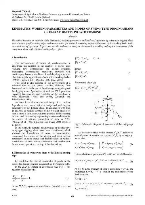
附件3外文文献原文Clusters and Competitiveness——A New Federal Role For Stimulating Regional EconomiesByKaren lsElisabeth B.ReynoldsAndrew ReamerClusters reinvigorate regional competitiveness. In recent decades, the nation’s economic dominance has eroded across an array of industries and business functions. In the decades following World War II, the United States built world-leading industries that provided well-paying jobs and economic prosperity to the nation. This dominance flowed from the nation’s e xtraordinary aptitude for innovation as well as a relative lack of international competition. Other nations could not match the economic prowess of the U.S. due to some combination of insufficient financial, human, and physical capital and economic and social systems that did not value creativity and entrepreneurship.However, while the nation today retains its preeminence in many realms, the dramatic expansion of economic capabilities abroad has seen the U.S. cede leadership, market share, and jobs in an ever-growing, wide-ranging list of industries and business functions. Initially restricted to labor-intensive, lower-skill activities such as apparel and electronic parts manufacturing, the list of affected U.S. operations has expanded to labor-intensive, higher-skill ones such as furniture-making and technical support call centers; capital-intensive, higher-skill ones such as auto, steel, and information technology equipment manufacturing; and, more recently, research and development (R&D) activities in sectors as diverse as computers and consumer products. Looking ahead, the nation’s capability for generating and sustaining stable, sufficiently well-paying jobs for a large number of U.S. workers is increasingly at risk. Across numerous industries, U.S.-based operations have not been fully effective inresponding to competitive challenges from abroad. Many struggle to develop and adopt the technological innovations (in products and production processes) and institutional innovations (new ways of organizing firms and their relationships with customers, suppliers, and collaborators) that sustain economic activity and high-skill, high value-added jobs. As a result, too many workers are losing decent jobs without prospect of regaining them and too many regions are struggling economically.In this environment, regional industry clusters provide a valuable mechanism for boosting national and regional competitiveness. Essentially, an industry cluster is a geographic concentration of interconnected businesses, suppliers, service providers, and associated institutions in a particular field.Defined by relationships rather than a particular product or function, clusters include organizations across multiple traditional industrial classifications (which makes drawing the categorical boundaries of a cluster a challenge). Specifically, participants in an industry cluster include:•organizations providing similar and related goods or services•specialized suppliers of goods, services, and financial capital (backward linkages)•distributors and local customers (forward linkages)•companies with complementary products (lateral linkages)•companies employing related skills or technologies or common inputs (lateral linkages)•related research, education, and training ins titutions such as universities, community colleges, and workforce training programs•cluster support organizations such as trade and professional associations, business councils, and standards setting organizationsThe power of clusters to advance regional economic growth was described (using the term ―industrial districts‖) in the pioneering work of Alfred Marshall in 1890. With the sizeable upswing in regional economic restructuring in recent decades, understanding of and interest in the role of clusters in regional competitiveness again has come to the fore through the work of a number of scholars and economic development practitioners.In particular, the efforts of Michael Porter, in a dual role as scholar and development practitioner, have done much to develop and disseminate the concept.Essentially, industry clusters develop through the attractions of geographic proximity—firms find that the geographic concentration of similar, related,complementary, and supporting organizations offers a wide array of benefits. Clusters promote knowledge sharing (―spillovers‖) and innovations in products and in technical and business processes by providing thick networks of formal and informal relationships across organizations. As a result, companies derive substantial benefits from participation in a cluster’s ―social structure of innovation.‖A number of studies indicate a positive correlation between clusters and patenting rates, one measure of the innovation process.What is more, clusters enhance firm access to specialized labor, materials, and equipment and enable lower operating costs. Highly concentrated markets attract skilled workers by offering job mobility and specialized suppliers and service providers—such as parts makers, workforce trainers, marketing firms, or intellectual property lawyers—by providing substantial business opportunities in close proximity. And concentrated markets tend to provide firms with various cost advantages; for example, search costs are reduced, market economies of scale can cut costs, and price competition among suppliers can be heightened.Entrepreneurship is one important means through which clusters achieve their benefits. Dynamic clusters offer the market opportunities and the conditions—culture, social networks, inter-firm mobility, access to capital—that encourage new business development.In sum, clusters stimulate innovation and improve productivity. In so doing, they are a critical element of national and regional competitiveness. After all, the nation’s econom y is essentially an amalgamation of regional ones, the health of which depends in turn on the competitiveness of its traded sector—that part of the economy which provides goods and services to markets that extend beyond the region. In metropolitan areas and most other economic regions of any size, the traded sector contains one or more industry clusters.In this respect, the presence and strength of industry clusters has a direct effect on economic performance as demonstrate a number of recent studies. A strong correlation exists between gross domestic product per capita and cluster concentrations.Several studies show a positive correlation between cluster strength and wage levels in cluster.And a third set of studies indicates that regions with strong clusters have higher regional and traded sector wages.For purposes of economic development policy, meanwhile, it should be kept in mind that every cluster is unique. Clusters come in a variety of purposes, shapes,and sizes and emerge out of a variety of initial conditions. (See Appendix A for examples.) The implication is that one size, in terms of policy prescription, does not fit all.Moreover, clusters differ considerably in their trajectory of growth, development, and adjustment in the face of changing market conditions. The accumulation of evidence suggests, in this respect, that there are three critical factors of cluster success: collaboration (networks and partnerships), skills and abilities (human resources), and organizational capacities to generate and take advantage of innovations.Any public policy for clusters, then, needs to aim at spurring these success factors.Policy also needs to recognize that cluster success breeds success: The larger a cluster, the greater the benefits it generates in terms of innovation and efficiencies, the more attractive it becomes to firms, entrepreneurs, and workers as a place to be, the more it grows, and so on. As a result, most sectors have a handful of dominant clusters in the U.S. As the dominant sectors continually pull in firms, entrepreneurs, and workers, it is difficult for lower tier regions to break into the dominant group.For instance, the biotech industry is lead by the Boston and San Francisco clusters, followed by San Diego, Seattle, Raleigh-Durham, Washington-Baltimore, and Los Angeles.Moreover, as suggested by the biotech example, the dominant clusters tend to be in larger metro areas. Larger metros (almost by definition) tend to have larger traded clusters, which offer a greater degree of specialization and diversity, which lead to patenting rates almost three times higher than smaller metros.The implication is that public policy needs to be realistic; not every region can be, as many once hoped, the next Silicon Valley.At the same time, not even Silicon Valley can rest on its laurels. While the hierarchy of clusters in a particular industry may be relatively fixed for a period of time, the transformation of the American industrial landscape from the 1950s—when Detroit meant cars, Pittsburgh meant steel, and Hartford meant insurance—to the present makes quite clear that cluster dominance cannot be taken for granted. This is true now more than ever—as innovation progresses, many clusters have become increasingly vulnerable, for three related reasons.First, since the mid-20th century, transportation and communications innovations have allowed manufacturers to untether production capacity from clusters and scatter isolated facilities around the nation and the world, to be closer to new markets and totake advantage of lower wage costs. Once relatively confined to the building of ―greenfield‖ branch plants in less industrial, non-union areas of the U.S., the shift of nondurables manufacturing to non-U.S. locations is a more recent manifestation of this phenomenon. Further, these innovations have enabled foreign firms to greatly increasetheir share of markets once dominated by American firms and their associated home-based clusters.Second, more recent information technology innovations have allowed the geographic disaggregation of functions that traditionally had been co-located in a single cluster. Firms now have the freedom to place headquarters, R&D, manufacturing, marketing and sales, and distribution and logistics in disparate locations in light of the particular competitive requirements (e.g., skills, costs, access to markets) of each function.As a result, firms often locate operations in function-specific clusters. The geographic fragmentation of corporate functions has had negative impacts on many traditional, multi-functional clusters, such as existed in 1960. At the same time, it offers opportunities, particularly for mid-sized and smaller areas, to develop clusters around highly specific functions that may serve a variety of industry sectors. For instance, Memphis, TN and Louisville, KY have become national airfreight distribution hubs. Relying on Internet technologies, firms such as IBM and Procter & Gamble are creating virtual clusters, cross-geography ―collaboratories.‖However, by whatever name and changes in information technology, the benefits of the geographic agglomeration of economic activity will continue for the foreseeable future.)Third, as radically new products and services disrupt existing markets, new clusters that produce them can do likewise. For instance, the transformation in the computer industry away from mainframes and then from minicomputers in the 1970s and 1980s led to a shift in industry dominance from the Northeast to Silicon Valley and Seattle.In the new world of global competition, the U.S. and its regions are in a perpetual state of economic transition. Industries rise and fall, transform products and processes, and move around the map. As a result, regions across the U.S. are working hard to sustain a portfolio of competitive clusters and other traded activities that provide decent jobs. In this process, some regional economies are succeeding for the moment, while others are struggling. For U.S. regions, states, and particularly the federal government, the challenge is to identify and pursue mechanisms—clusterinitiatives, in particular—to enhance the competitiveness of existing clusters while taking advantage of opportunities to develop new ones.Cluster initiatives stimulate cluster competitiveness and growth. Cluster initiatives are formally organized efforts to promote cluster competitiveness and growth through a variety of collaborative activities among cluster participants.Examples of such collaborative efforts include:•facilitating mark et development through joint market assessment, marketing,and brand-building•encouraging relationship-building (networking) within the cluster, within the region, and with clusters in other locations•promoting collaborative innovation –research, product and process development, and commercialization•aiding the innovation diffusion, the adoption of innovative products, processes, and practices•supporting the cluster expansion through attracting firms to the area and supporting new business development•sponsoring education and training activities•representing cluster interests before external organizations such as regional development partnerships, national trade associations, and local, state, and federal governmentsWhile cluster initiatives have existed for some time, research indicates that the number of such initiatives has grown substantially around the world in a short period of time. In 2003, the Global Cluster Initiative Survey (GCIS) identified over 500 cluster initiatives in Europe, North America, Australia, and New Zealand; 72 percent of these had been created during the previous four years.That number likely has expanded significantly in the last five years. Today, the U.S. alone has several hundred distinct cluster initiatives.A look across the breadth of cluster initiatives indicates the following:•Clusters are present across the full array of i ndustry sectors, including both manufacturing and services—as examples, initiatives exist in information technology, biomedical, photonics, natural resources, communications, and the arts •They are almost always in sectors of economic importance, in other words, they tend not to be frivolously or naively chosen•They carry out a diverse set of activities, typically in four to six of the b ulleted categories on the previous page•While the geographic boundaries of many are natural economic regions such as metro areas, others follow political boundaries, such as states•Typically, they are industry-led, with active involvement from government and nonprofit organizations•In terms of legal structure, they can be sponsored by existing collaborative institutions such as chambers of commerce and trade associations or created as new sole-purpose nonprofits (e.g., the North Star Alliance)•Most have a dedicated facilitator•The number of participants in a cluster initiative can range from a handful to over 500•Almost every cluster initiative is unique when the combination of regional setting, industry, size, range of objectives and activities, development, structure, and financing are consideredSuccessful cluster initiatives:•are industry-led•involve state and local government decisionmakers that can be supportive•are inclusive: They seek any and all organizations that might find benefi t from participation, including startups, firms not locally-owned, and firms rival to existing members•create consensus regarding vision and roadmap (mission, objectives, how to reach them)•encourage broad participation by members and collaboration amon g all types of participants in implementing the roadmap•are well-funded initially and self-sustaining over the long-term•link with relevant external efforts, including regional economic development partnerships and cluster initiatives in other locationsAs properly organized cluster initiatives can effectively promote cluster competitiveness, it is in the nation’s interest to have well-designed, well-implemented cluster initiatives in all regions. Cluster initiatives often emerge as a natural, firm-led outgrowth of cluster development. For example, the Massachusetts Biotechnology Council formed out of a local biotech softball league.However, left to the initiative of cluster participants, a good number of possible cluster initiatives never see reality because of a series of barriers to the efficient working of markets (what economists call ―market failures‖). First are ―public good‖ and ―free rider‖ problems. In certain instances, individual firms, particularly smallones, will under-invest in cluster a ctivities because any one firm’s near-term cost in time, money, and effort will outweigh the immediate benefits it receives. So no firm sees the incentive to be an early champion or organizer. Further, because all firms in the cluster benefit from the work of early champions (―public good‖), many are content to sit back and wait for others to take the lead (be a ―free rider‖).Consequently, if cluster firms are left to their own devices and no early organizers emerge, a sub-optimal amount of cluster activity will occur and the cluster will lose the economic benefits that collaboration could bring.Some firms have issues of mistrust, concerns about collaborating with the competition. In certain industries in certain regions, competition among firms is so intense that a culture of secrecy and suspicion has developed that stymies mutually beneficial cooperation.Even if the will to organize a cluster initiative is present, the way may be impeded by a variety of factors. Cluster initiatives may not get off the ground because would-be organizers lack knowledge about the full array of organizations in the cluster, relationships or standing with key organizations (i.e., lack the power to convene), financial resources to organize, or are uncertain about how organizin g should best proceed. They see the ―transaction costs‖ of overcoming these barriers (that is, seeking information, building relationships, raising money) as too high to move forward. In the face of the various barriers to self-generating cluster initiatives, public purpose organizations such as regional development partnerships and state governments are taking an increasingly active role in getting cluster initiatives going. So, for example, the Massachusetts Technology Collaborative, a quasi-public state agency, was instrumental in initiating the Massachusetts Medical Device Industry Council (inresponse to an economic development report to the governor prepared by Michael Porter). And Maine’s North Star Alliance was created through the effort of that state’s governor.However, a number of states and regional organizations—and national governments elsewhere—have come to understand that creating single cluster initiatives in ad hoc, ―one-off‖ manner is an insufficient response to the problem and the opportunity. Rather, as discussed in the next section, they have created formal on-going programs to seed and support a series of cluster initiatives. Even so, the nation’s network of state and regional cluster init iatives is thin and uneven in terms of geographic and industry coverage. Consequently, the nation’s ability to stay competitive and provide well-paying jobs across U.S. regions is diminished; broader, thoughtful federal action is necessary.。

5.6 The Network Layer in the InternetBefore getting into the specifics of the network layer in the Internet, it is worth taking at look at the principles that drove its design in the past and made it the success that it is today. All too often, nowadays, people seem to have forgotten them. These principles are enumerated and discussed in RFC 1958, which is well worth reading (and should be mandatory for all protocol designers—with a final exam at the end). This RFC draws heavily on ideas found in (Clark, 1988; and Saltzer et al., 1984). We will now summarize what we consider to be the top 10 principles (from most important to least important).1.Make sure it works. Do not finalize the design or standard untilmultiple prototypes have successfully communicated with each other.All too often designers first write a 1000-page standard, get it approved, then discover it is deeply flawed and does not work. Then they write version 1.1 of the standard. This is not the way to go.2.Keep it simple. When in doubt, use the simplest solution. Williamof Occam stated this principle (Occam's razor) in the 14th century.Put in modern terms: fight features. If a feature is not absolutely essential, leave it out, especially if the same effect can beachieved by combining other features.3.Make clear choices.If there are several ways of doing the same thing,choose one. Having two or more ways to do the same thing is looking for trouble. Standards often have multiple options or modes orparameters because several powerful parties insist that their way is best. Designers should strongly resist this tendency. Just say no.4.Exploit modularity. This principle leads directly to the idea ofhaving protocol stacks, each of whose layers is independent of all the other ones. In this way, if circumstances that require onemodule or layer to be changed, the other ones will not be affected.5.Expect heterogeneity. Different types of hardware, transmissionfacilities, and applications will occur on any large network. To handle them, the network design must be simple, general, andflexible.6.Avoid static options and parameters.If parameters are unavoidable(e.g., maximum packet size), it is best to have the sender andreceiver negotiate a value than defining fixed choices.7.Look for a good design; it need not be perfect.Often the designershave a good design but it cannot handle some weird special case.Rather than messing up the design, the designers should go with thegood design and put the burden of working around it on the people with the strange requirements.8.Be strict when sending and tolerant when receiving.In other words,only send packets that rigorously comply with the standards, but expect incoming packets that may not be fully conformant and try to deal with them.9.Think about scalability. If the system is to handle millions ofhosts and billions of users effectively, no centralized databases of any kind are tolerable and load must be spread as evenly aspossible over the available resources.10.Consider performance and cost. If a network has poor performanceor outrageous costs, nobody will use it.Let us now leave the general principles and start looking at the details of the Internet's network layer. At the network layer, the Internet can be viewed as a collection of subnetworks or Autonomous Systems (ASes) that are interconnected. There is no real structure, but several major backbones exist. These are constructed from high-bandwidth lines and fast routers. Attached to the backbones are regional (midlevel) networks, and attached to these regional networks are the LANs at many universities, companies, and Internet service providers. A sketch of thisquasi-hierarchical organization is given in Fig. 5-52.Figure 5-52. The Internet is an interconnected collection of many networks.The glue that holds the whole Internet together is the network layer protocol, IP (Internet Protocol). Unlike most older network layer protocols, it was designed from the beginning with internetworking in mind.A good way to think of the network layer is this. Its job is to providea best-efforts (i.e., not guaranteed) way to transport datagrams from source to destination, without regard to whether these machines are on the same network or whether there are other networks in between them.Communication in the Internet works as follows. The transport layer takes data streams and breaks them up into datagrams. In theory, datagrams can be up to 64 Kbytes each, but in practice they are usually not more than 1500 bytes (so they fit in one Ethernet frame). Each datagram is transmitted through the Internet, possibly being fragmented into smaller units as it goes. When all the pieces finally get to the destination machine, they are reassembled by the network layer into the original datagram. This datagram is then handed to the transport layer, which inserts it into the receiving process' input stream. As can be seen from Fig. 5-52, a packet originating at host 1 has to traverse six networks to get to host 2. In practice, it is often much more than six.5.6.1 The IP ProtocolAn appropriate place to start our study of the network layer in the Internet is the format of the IP datagrams themselves. An IP datagram consists of a header part and a text part. The header has a 20-byte fixed part and a variable length optional part. The header format is shown in Fig. 5-53. It is transmitted in big-endian order: from left to right, with the high-order bit of the Version field going first. (The SPARC is big endian; the Pentium is little-endian.) On little endian machines, software conversion is required on both transmission and reception.Figure 5-53. The IPv4 (Internet Protocol) header.The Version field keeps track of which version of the protocol the datagram belongs to. By including the version in each datagram, it becomes possible to have the transition between versions take years, with some machines running the old version and others running the new one. Currently atransition between IPv4 and IPv6 is going on, has already taken years, and is by no means close to being finished (Durand, 2001; Wiljakka, 2002; and Waddington and Chang, 2002). Some people even think it will never happen (Weiser, 2001). As an aside on numbering, IPv5 was an experimental real-time stream protocol that was never widely used.Since the header length is not constant, a field in the header, IHL, is provided to tell how long the header is, in 32-bit words. The minimum value is 5, which applies when no options are present. The maximum value of this 4-bit field is 15, which limits the header to 60 bytes, and thus the Options field to 40 bytes. For some options, such as one that records the route a packet has taken, 40 bytes is far too small, making that option useless.The Type of service field is one of the few fields that has changed its meaning (slightly) over the years. It was and is still intended to distinguish between different classes of service. Various combinations of reliability and speed are possible. For digitized voice, fast delivery beats accurate delivery. For file transfer, error-free transmission is more important than fast transmission.Originally, the 6-bit field contained (from left to right), a three-bit Precedence field and three flags, D, T, and R. The Precedence field was a priority, from 0 (normal) to 7 (network control packet). The three flag bits allowed the host to specify what it cared most about from the set {Delay, Throughput, Reliability}. In theory, these fields allow routers to make choices between, for example, a satellite link with high throughput and high delay or a leased line with low throughput and low delay. In practice, current routers often ignore the Type of service field altogether.Eventually, IETF threw in the towel and changed the field slightly to accommodate differentiated services. Six of the bits are used to indicate which of the service classes discussed earlier each packet belongs to. These classes include the four queueing priorities, three discard probabilities, and the historical classes.The Total length includes everything in the datagram—both header and data. The maximum length is 65,535 bytes. At present, this upper limit is tolerable, but with future gigabit networks, larger datagrams may be needed.The Identification field is needed to allow the destination host to determine which datagram a newly arrived fragment belongs to. All the fragments of a datagram contain the same Identification value.Next comes an unused bit and then two 1-bit fields. DF stands for Don't Fragment. It is an order to the routers not to fragment the datagram because the destination is incapable of putting the pieces back together again. For example, when a computer boots, its ROM might ask for a memory image to be sent to it as a single datagram. By marking the datagram with the DF bit, the sender knows it will arrive in one piece, even if this means that the datagram must avoid a small-packet network on the best path and take a suboptimal route. All machines are required to accept fragments of 576 bytes or less.MF stands for More Fragments. All fragments except the last one have this bit set. It is needed to know when all fragments of a datagram have arrived.The Fragment offset tells where in the current datagram this fragment belongs. All fragments except the last one in a datagram must be a multiple of 8 bytes, the elementary fragment unit. Since 13 bits are provided, there is a maximum of 8192 fragments per datagram, giving a maximum datagram length of 65,536 bytes, one more than the Total length field.The Time to live field is a counter used to limit packet lifetimes. It is supposed to count time in seconds, allowing a maximum lifetime of 255 sec. It must be decremented on each hop and is supposed to be decremented multiple times when queued for a long time in a router. In practice, it just counts hops. When it hits zero, the packet is discarded and a warning packet is sent back to the source host. This feature prevents datagrams from wandering around forever, something that otherwise might happen if the routing tables ever become corrupted.When the network layer has assembled a complete datagram, it needs to know what to do with it. The Protocol field tells it which transport process to give it to. TCP is one possibility, but so are UDP and some others. The numbering of protocols is global across the entire Internet. Protocols and other assigned numbers were formerly listed in RFC 1700, but nowadays they are contained in an on-line data base located at .The Header checksum verifies the header only. Such a checksum is useful for detecting errors generated by bad memory words inside a router. The algorithm is to add up all the 16-bit halfwords as they arrive, using one's complement arithmetic and then take the one's complement of the result. For purposes of this algorithm, the Header checksum is assumed to be zero upon arrival. This algorithm is more robust than using a normal add. Note that the Header checksum must be recomputed at each hop because at least one field always changes (the Time to live field), but tricks can be used to speed up the computation.The Source address and Destination address indicate the network number and host number. We will discuss Internet addresses in the next section. The Options field was designed to provide an escape to allow subsequent versions of the protocol to include information not present in the original design, to permit experimenters to try out new ideas, and to avoid allocating header bits to information that is rarely needed. The options are variable length. Each begins with a 1-byte code identifying the option. Some options are followed by a 1-byte option length field, and then one or more data bytes. The Options field is padded out to a multiple of four bytes. Originally, five options were defined, as listed in Fig. 5-54, but since then some new ones have been added. The current complete list is now maintained on-line at /assignments/ip-parameters.Figure 5-54. Some of the IP options.The Security option tells how secret the information is. In theory, a military router might use this field to specify not to route through certain countries the military considers to be ''bad guys.'' In practice, all routers ignore it, so its only practical function is to help spies find the good stuff more easily.The Strict source routing option gives the complete path from source to destination as a sequence of IP addresses. The datagram is required to follow that exact route. It is most useful for system managers to send emergency packets when the routing tables are corrupted, or for making timing measurements.The Loose source routing option requires the packet to traverse the list of routers specified, and in the order specified, but it is allowed to pass through other routers on the way. Normally, this option would only provide a few routers, to force a particular path. For example, to force a packet from London to Sydney to go west instead of east, this option might specify routers in New York, Los Angeles, and Honolulu. This option is most useful when political or economic considerations dictate passing through or avoiding certain countries.The Record route option tells the routers along the path to append their IP address to the option field. This allows system managers to track downbugs in the routing algorithms (''Why are packets from Houston to Dallas visiting Tokyo first?''). When the ARPANET was first set up, no packet ever passed through more than nine routers, so 40 bytes of option was ample. As mentioned above, now it is too small.Finally, the Timestamp option is like the Record route option, except that in addition to recording its 32-bit IP address, each router also records a 32-bit timestamp. This option, too, is mostly for debugging routing algorithms.5.6.2 IP AddressesEvery host and router on the Internet has an IP address, which encodes its network number and host number. The combination is unique: in principle, no two machines on the Internet have the same IP address. All IP addresses are 32 bits long and are used in the Source address and Destination address fields of IP packets. It is important to note that an IP address does not actually refer to a host. It really refers to a network interface, so if a host is on two networks, it must have two IP addresses. However, in practice, most hosts are on one network and thus have one IP address.For several decades, IP addresses were divided into the five categories listed in Fig. 5-55. This allocation has come to be called classfuladdressing.Itisno longer used, but references to it in the literature are still common. We will discuss the replacement of classful addressing shortly.Figure 5-55. IP address formats.The class A, B, C, and D formats allow for up to 128 networks with 16 million hosts each, 16,384 networks with up to 64K hosts, and 2 million networks (e.g., LANs) with up to 256 hosts each (although a few of these are special).Also supported is multicast, in which a datagram is directed to multiple hosts. Addresses beginning with 1111 are reserved for future use. Over 500,000 networks are now connected to the Internet, and the number grows every year. Network numbers are managed by a nonprofit corporation called ICANN (Internet Corporation for Assigned Names and Numbers) to avoid conflicts. In turn, ICANN has delegated parts of the address space to various regional authorities, which then dole out IP addresses to ISPs and other companies.Network addresses, which are 32-bit numbers, are usually written in dotted decimal notation. In this format, each of the 4 bytes is written in decimal, from 0 to 255. For example, the 32-bit hexadecimal address C0290614 is written as 192.41.6.20. The lowest IP address is 0.0.0.0 and the highest is 255.255.255.255.The values 0 and -1 (all 1s) have special meanings, as shown in Fig. 5-56. The value 0 means this network or this host. The value of -1 is used as a broadcast address to mean all hosts on the indicated network.Figure 5-56. Special IP addresses.The IP address 0.0.0.0 is used by hosts when they are being booted. IP addresses with 0 as network number refer to the current network. These addresses allow machines to refer to their own network without knowing its number (but they have to know its class to know how many 0s to include). The address consisting of all 1s allows broadcasting on the local network, typically a LAN. The addresses with a proper network number and all 1s in the host field allow machines to send broadcast packets to distant LANs anywhere in the Internet (although many network administrators disable this feature). Finally, all addresses of the form 127.xx.yy.zz are reserved for loopback testing. Packets sent to that address are not put out onto the wire; they are processed locally and treated as incoming packets. This allows packets to be sent to the local network without the sender knowing its number.。
外文文献翻译(附原文)外文译文一:产业集群的竞争优势——以中国大连软件工业园为例Weilin Zhao,Chihiro Watanabe,Charla-Griffy-Brown[J]. Marketing Science,2009(2):123-125.摘要:本文本着为促进工业的发展的初衷探讨了中国软件公园的竞争优势。
产业集群深植于当地的制度系统,因此拥有特殊的竞争优势。
根据波特的“钻石”模型、SWOT模型的测试结果对中国大连软件园的案例进行了定性的分析。
产业集群是包括一系列在指定地理上集聚的公司,它扎根于当地政府、行业和学术的当地制度系统,以此获得大量的资源,从而获得产业经济发展的竞争优势。
为了成功驾驭中国经济范式从批量生产到开发新产品的转换,持续加强产业集群的竞争优势,促进工业和区域的经济发展是非常有必要的。
关键词:竞争优势;产业集群;当地制度系统;大连软件工业园;中国;科技园区;创新;区域发展产业集群产业集群是波特[1]也推而广之的一个经济发展的前沿概念。
作为一个在全球经济战略公认的专家,他指出了产业集群在促进区域经济发展中的作用。
他写道:集群的概念,“或出现在特定的地理位置与产业相关联的公司、供应商和机构,已成为了公司和政府思考和评估当地竞争优势和制定公共决策的一种新的要素。
但是,他至今也没有对产业集群做出准确的定义。
最近根据德瑞克、泰克拉[2]和李维[3]检查的关于产业集群和识别为“地理浓度的行业优势的文献取得了进展”。
“地理集中”定义了产业集群的一个关键而鲜明的基本性质。
产业由地区上特定的众多公司集聚而成,他们通常有共同市场、,有着共同的供应商,交易对象,教育机构和其它像知识及信息一样无形的东西,同样地,他们也面临相似的机会和威胁。
在全球产业集群有许多种发展模式。
比如美国加州的硅谷和马萨诸塞州的128鲁特都是知名的产业集群。
前者以微电子、生物技术、和风险资本市场而闻名,而后者则是以软件、计算机和通讯硬件享誉天下[4]。
e c o l o g i c a l e n g i n e e r i n g 28(2006124–130a v a i l ab l e a t w w w.sc i e n c ed i re c t.c omj o u r n a l h o m e p a g e :w w w.e l s e v i e r.c o m /l o c a t e /e c o l e n gPlant-biofilm oxidation ditch for in situ treatm ent of polluted watersQi-Tang Wu a ,∗,Ting Gao a ,Shucai Zeng a ,Hong Chua ba College of Natural Resources and Environment,South China Agricultural University,Guangzhou 510642,ChinabDepartment of Civil and Structural Engineering,Hong Kong Polytechnic University,Hung Hom,Kowloon,Hong Kong SAR,Chinaa r t i c l ei n f o Article history:Received 17December 2005Received in revised form 16May 2006Accepted 18May 2006Keywords:Plant-biofilm oxidation ditch (PBFODIn situWastewater treatmenta b s t r a c tEutrophication of surface water bodies is a problem of increasing environmental and ecolog-ical concern worldwide and is particularly serious in China.In the present study,oxidation ditches were connected to a lake receiving municipal sewage sludges.T wo 24m 2(width 2m,length 12mparallel plastic oxidation ditches material were installed on a lake near the inlet of the municipal sewage.Zizania caduciflora and Canna generalis were grown in the ditches with plastic floating supporters for the removal of N and P from the sewage.The experiment was conducted firstly with municipal sewage in autumn–winter seasons for about 150daysunder the following conditions:2m 3/h influent flow,0.75kW jet-flow aerator(air/water of 5,18h HRT (hydrological retention timeand a return ratio of 10.Then it was run with the polluted lake water in summer–autumn for about 160days with an aerator of 1.25kW and an influent of 6m 3/h (air/water 3.3,HRT 6h.The performance was quite stable during the experimental period for the municipal sewage treatment.The average removal rates of COD (chemical oxygen demand,SS (suspended solids,TP (total phosphorus,NH 4+-N and inorganic-N were 70.6,75.8,72.6,52.1and50.3%,respectively.For the polluted lake water treatment,the average concentrations of COD,NH 4+-N and TP were 42.7,13.1and 1.09mg/L,respectively,in the influent and were 25.1,6.4and 0.38mg/L,respectively,in the effluent.The capacity of the plants to remove N and P by direct uptake was limited,but the indi-rect mechanisms also occurred.The proposed process,transforming the natural lake into a wastewater treatment plant,could evidently reduce the costs of the sewage collection,the land space requirement and the construction compared with conventional sewage treat-ment plants,and is especially suited to conditions in south China and south-east Asia.©2006Elsevier B.V .All rights reserved.1.IntroductionMany water bodies are subject to eutrophication due to eco-nomic constraints in reducing point sources of nutrients and/or to a high proportion of diffuse sources,and the prob-lem is particularly common in China because the proportion of treated municipal sewage is still low due to the relatively high capital investmentrequired.Accordingly,43.5%of 130investi-gated major lakes in China were found to be highly eutrophied∗Corresponding author .Tel.:+862085280296;fax:+862085288326.E-mail address:qitangwu@ (Q.-T.Wu.and 45%were of intermediate status (Li et al.,2000.These pol-luted lakes were mainly located in economically developed regions and especially around cities where large amounts of municipal sewage are discharged without appropriate treat-ment.Increasingly,natural or constructed wetlands,including buffer zones(Correll,2005,are being used for removal of pol-lutants from wastewater or for treatment of stormwater runoff from agricultural land and other non-point sources (Mitsch ete c o l o g i c a l e n g i n e e r i n g28(2006124–130125Table1–COD and BOD5of the study lake sampled at three points for5days inMay2003COD(mg/LBOD5(mg/LBOD5/COD13May89.5135.700.4083.3334.500.4189.5136.600.4114May55.5624.800.4589.5135.200.3949.3820.900.4227May105.1141.300.3981.0832.300.40111.1141.000.3728May60.0026.830.4563.3327.700.4463.3327.000.4329May90.0035.700.4093.3337.000.40117.9949.400.42al.,2000;Coveney et al.,2002;Belmont et al.,2004.However, this method requires a large land area in addition to the lake in question.For in situ treatment of hypereutrophic water bodies where the transparency of the water does not allow regrowth of submerged macrophytes,phosphorus precipitation in eutrophic lakes by iron application(Deppe and Benndorf, 2002or by additions of lime(Walpersdorf et al.,2004has been reported.Aeration of river water has been employed to remediate polluted rivers since the1970s(Wang et al.,1999. Increasing oxygen transfer inflow by stones placed in rivers was studied by Cokgor and Kucukali(2004.Growingfloating aquatic macrophytes(Sooknah and Wilkie,2004or terrestrial green plants usingfloating supports(Li and Wu,1997,physical ecological engineering(PEEN(Pu et al.,1998,and biotic addi-tives have also been applied(Chen,2003.However,these sim-ple designs do not constitute a real water treatment system and the efficiencies of these treatments are unsatisfactory.Activated sludge systems have been proved efficient treat-ing municipal sewage since the1960s(Ray,1995.However, this type of system has not been used for in situ remediation of polluted lakes or rivers.In the present study,the oxidation ditch technique was adopted on a lake receiving municipal sewage sludge.Floating green plants and the biofilms com-prisingfloating materials and plant roots were also added to enhance N and P removal.A pilot scale experiment was set up to test the feasibility and performance of the plant-enhanced oxidation ditch for in situ treatment ofboth the municipal sewage and the polluted lake water.2.Experimental2.1.Site descriptionThe study lake was situated at South China Agricultural Uni-versity,Guangzhou,China.The area of the lake was about 10000m2and the depth0.5–3m.This lake received the munic-ipal sewage from the residential area around the university.Fig.1–Surface arrangement of the plant-biofilm oxidation ditch and the waterflows.(1Wall of nylon tissue;(2nets of5mm;(3nets of0.25mm;(4oxidation ditch;(5jet-flow aerator;(6water pump;(7floating green plants;(8sewage entry.2.2.Establishment of the plant-biofilm oxidationditchesT wo24m2(width2m,length12mparallel oxidation ditches made of plastic materials were installed along the lake bank near the sewage inlet.The inner ditch was made of cement and the outer ditch was isolated with nylon tissues andfix-ing PVC(polyvinyl chloridetubes.Fig.1showsthe surface arrangement and the waterflow path.The coarse suspended solids in the influent werefiltered by two pl astic nets,one with a pore size of5mm and the other with a pore size of0.25mm,whereas the suspended solids in the effluent werefiltered by a plastic net with a pore size of 0.25mm.Zizania caduciflora and Canna generalis were grown in the ditch with theplast icfloating supporters which held the plants in position.Thefloating supporters were made of closed126e c o l o g i c a l e n g i n e e r i n g28(2006124–130PVC tubes and nylon nets and each was3.6m2.Zizania caduci-flora was grown on twofloating supporters an d Canna gener-alis on another two supporters.The plants were planted in four columns andfive lines.The twofloating supporters with Canna generalis were near the influent and the two with Zizania caduciflora were near the effluent.The entire disposal system is shown in Photo1.2.3.Conduct of the experimentsAn experiment was conductedfirstly on municipal sewage in autumn–winter seasons of2003–2004for about150days. The aeration of the oxidation ditch was achieved using a jet-flow aerator of0.75kW(Aqua Co.,Italy;air generation10m3/h, water jet rate22–28m3/h.The water sampling started on18 September2003and endedon12February2004.The influent was2m3/h created by a water pump of0.37kW.With the jet-flow aerator of0.75kW the theoretical air/water ratio was5, HRT was18h and the return ratio was10–13.The system was then run with the polluted lake water in summer and autumn2004for about160days with an aerator of1.25kW and with an influent of6m3/h(air/water3.3,HRT 6h.The influent was not created by water pump but by the driving fo rce of the jet-flow aerator.The water sampling for the second run started on15May2004and endedon15October 2004.2.4.Sampling and analysisThe influent and effluent were sampled every3–5days at 08:00–09:00a.m.andat17:00–18:00p.m.,each with three sam-pling re plicates for thefirst run.For the second run,the influ-ent and effluent were sampled1day a week.The water sam-pler took0–30cm surface water.The samples were analyzed for COD Cr,BOD5,SS,TP,NO3−-N,NH4+-N and pH according to standard methods(APHA,1995.The plant s were transplanted ontofloating supporters two weeks before water sampling and thefirst harvest was carried out60days later and at the termination of thefirst run for the municipal sewage.The plant biomass and N and P con-tents were measured according to the methods proposed by the Soil and Agro-Chemical Analysis Committee of China(Lu, 2000.The total uptakes of N and P were calculated and com-pared with the total removal of these elements calculated by the cumulative removal each day following measurement of a water sample.Total N removal=(average N in influent−average N in effluent×48×D iwhere48was the treated water volume per day in m3/day;D i was the number of days following the water sampling and before the next sampling.3.Results and discussionTable2shows the removal of COD Cr and SS by plant-biofilm oxidation ditch for the treatment of the municipal sewage in autumn–winter seasons of2003–2004.The removal of COD Cr varied from60to79%with an average of70%for the influent COD Cr ranging from100to200mg/L,a nd resulted in effluent COD Cr valuesfrom30to55mg/L(Table2,Fig.2.The average removal percentage was about75%for SS and variedfrom68to82%(Table2.The effluent SS was about 30mg/L which is the effluent limit value of the second grade for the sewage treatment plants in China(GB18918,2002 (Fig.3,for the influents varying from60to240mg/L.The average NH4+-N removal from influent was52%,which was lower in winter than in autumn(Table3.This may be due to lower bacterial activity in winter,but theinfluent NH4+-NTable2–Removal of COD and SS by the plant-biofilm oxidation ditch for the in situ treatment of municipal sewage each month in autumn–winter seasons of2003–2004Period Sampled days Water temperature(◦CInfluent(mg/LEffluent(mg/LRemoval(%COD Cr18–30September528.0118.54(3.01a34.34(7.8367.74 3–28October826.1123.91(4.0333.51(4.2672.661–7November326.0153.94(2.7337.60(3.8175.4918–28November423.1170.22(4.2835.45(5.3778.711–15December419.3180.36(8.2039.24(7.0677.6511–31January314.5128.46(3.6652.04(5.2359.504–12February216.8178.35(4.1662.86(5.8362.47Average150.54(4.3042.15(5.6370.60SS18–30September528.0160.4041.6074.18 3–28October826.1144.3826.2581.171–7November326.0116.0033.3370.7918–28November423.1111.7521.5080.981–15December419.390.5028.5068.4211–31January314.5104.0017.3382.384–12February216.8120.5033.0072.57Average121.0828.7975.78e c o l o g i c a l e n g i n e e r i n g28(2006124–130127Fig.2–COD in the influent and effluent of the plant-biofilm oxidation ditch for the in situ treatment of municipal sewage in autumn–winter seasons of2003–2004.was also higher in winter(Fig.4probably because of lower water consumption in the cold season.The total inorganic-N removal was similar to that for NH4+-N(Table3.NO3−-N concentrations were rather similar in the influent and the effluent.The total P removal varied from63to78%and was higher and more regular than N removal(Table3.The P concentra-tion in treated effluent was about1mg/L(Fig.5and conformed to the Chinese municipal sewage treatment standard which is set to3mg/L for second grade regions and1.5forfirst grade regions(GB18918,2002.Fig.6shows typical changes in the water quality param-eters for the sampling points from inlet to outlet.Thisindi-Fig.3–Suspended solids concentration in the influent and effluent of the p lant-biofilm oxidation ditch for the in situ treatment of municipal sewage in autumn–winter seasons of2003–2004.cates that COD and SS decreased gradually,but NH4+-N and TP dropped substantially following the mixing with the return water by the aerator and then decreased slowly,while NO3−-N and pH of the water remained virtually unchanged.The water DO increased dramatically following the aeration,decreased slowly thereafter and remained rather high even in the efflu-ent(about5.5mg/L.For the second run treating the polluted lake water on-site,the average influent COD Cr was42.7mg/L and the effluent 25.1mg/L for about160days during summer–autumn seasons (Fig.7.The removal of NH4+-N was about50%from about13.1 to6.4mg/L.Total-P in the effluents was rather stable,bei ngTable3–The removal of N and P by the plant-biofilm oxidation ditch for the in situ treatment of municipal sewage for each month in autumn–winter seasons of2003–2004Period Sampled days Water temperature(◦CInfluent(mg/LEffluent(mg/LRemoval(%NH4+-N18–30September528.020.60(0.30a7.16(0.2264.72 3–28October826.126.55(0.2310.15(0.2061.671–7November326.030.00(0.4113.67(0.2254.5118–28November423.135.15(0.7915.95(0.2653.991–15December419.335.89(0.3515.93(0.2755.1511–31January314.530.57(0.6918.59(0.2236.634–12February216.835.23(0.0521.61(0.0637.72Average30.57(0.4014.72(0.2152.06NH4+-N+NO3−-N18–30September528.023.06(0.159.24(0.1159.94 3–28October826.128.31(0.1212.01(0.1457.571–7November326.031.42(0.2114.58(0.1153.5918–28November423.136.32(0.4016.81(0.1353.721–15December419.337.41(0.1917.54(0.1453.1111–31January314.531.96(0.3720.07(0.1337.204–12February216.837.11(0.0323.35(0.0337.08Average32.23(0.2116.23(0.1150.32TP18–30September528.0 3.56(0.070.81(0.0475.56 3–28October826.1 4.01(0.140.87(0.0478.241–7November326.0 4.37(0.13 1.20(0.0472.5618–28November423.1 4.89(0.16 1.13(0.0776.661–15December319.5 4.86(0.80 1.38(0.2371.07 11–31January314.5 3.75(0.45 1.35(0.0363.32 4–12February216.8 4.75(0.10 1.51(0.0566.20 Average 4.31(0.16 1.16(0.0471.89128e c o l o g i c a l e n g i n e e r i n g 28(2006 124–130Fig.4–NH 4+-N concentration in the influent and effluent of the plant-biofilm oxidation ditch for the in situ treatment of municipal sewage in autumn–winter seasons of2003–2004.Fig.5–Total-P concentration in the influent and effluent of the plant-biofilm oxidation ditch for the in situ treatment of municipal sewage in autumn–winter seasons of2003–2004.Fig.6–T ypical changes in the pollutants in theplant-biofilm oxidation ditch during the in situ treatment ofFig.7–The influent and effluent concentrations of COD (up,NH 4+-N (medianand total-P (bottomin theplant-biofilm oxidation ditch treating polluted lake water.about 0.38mg/L from an average of 1.09mg/L in the influents.The removal of COD Cr ,NH 4+-N and Total-P was then quite sat-isfactory both for the municipal sewage and the polluted lake water.The removal of N and P was somewhat higher than con-ventional oxidation ditches,perhaps due to the existence of the plant-biofilm in the studiedsystem.However,the direct uptake rates of N and P by green plants were almost negligi-ble compared to the total removal of these elements by the whole system (Table4.However,the plants may have cre-ated localized anaerobic conditions by their root exudates and dead biomass and enhance the denitrification of N by micro-organisms as occurs in constructed wetlands (Hone,2000.Besides the green plants,the proposed system also con-tains biofilm coated to the plastic materials.The high velocity of return-fluent was different to the conventional oxidation ditch.Kugaprasatham et al.(1982showed that the increase of the fluent velocity could increase the density of the biofilm if the nutrient conditions were suitable for bacteria growth.Simultaneous nitrification/denitrification (SND(Van Mun ch etal.,1996may also occur in the system.Concerning the P removal of the system,biological phos-phate removal processes may occur but were not significant because there was no sludge removal and very little sludge precipitation after the run for treatment of municipal sewage.This may partly due to the existence of some ferric chains which were added to precipitate and fix the nylon tissue to the lake bottom,with formation of precipitates of ferric phos-e c o l o g i c a l e n g i n e e r i n g 2 8 ( 2 0 0 6 124–130 129 Table 4 – Proportions of N and P uptake by plants and total removal in the plant-biofilm oxidation ditch treating municipal sewage Date Days ZCa Harvested fresh biomass (g CG ZC 5 September–4 November 5 November–6 January Total or average a Plant uptake (g N CG 5.30 13.03 System removal (kg N CG P Percent of plant uptake N (% P (% P ZC 0.88 0.24 2.79 60 63 123 2200 625 9725 2750 4150 4.85 1.20 24.38 0.72 0.95 37.63 65.45 103.1 7.13 12.78 19.91 0.03 0.02 0.02 0.02 0.01 0.01 ZC: Zizania caduciflo ra; CG: Canna generalis. tained for at least 1 year. The actual mechanisms still remain to be identified. The oxidation ditch has been used for many years worldwide as an economical and efficient wastewater treatment technology that can remove COD, nitrogen and a fraction of the phosphorusefficiently. Anaerobic tanks (Liu et al., 2002 and phased isolation ditch systems with intra-channel clarifier (Hong et al., 2003 were added to the system to increase the TP removal efficiency. The proposed process takes an artificial process in combination with natural purification, transforming the natural lake into the wastewater treatment plant, and could evidently reduce the costs of sewage collection, the landspace requirement and the construction costs compared with the conventional sewage treatment plants. This process could be especially suitable to subtropical regions and to many water bodies in south China and southeast Asia where sewage treatment facilities are not well established. China. The authors are grateful to Dr. P. Christie, Department of Agricultural and Environmental Science, Queen’s University Belfast, UK, and Dr. Y. Ouyang, Department of Water Resources, St. Johns River Water Management District, Palatka, FL, USA, for their valuable suggestions and language corrections. references 4. Conclusions The present study adapted the oxidation ditch on the lake surface for in situ treatment of municipal sewage or polluted lake water in combination with plant biofilms for performing N and P removal, and running experiments at pilot scale for about 1.5 years resulted in the following observations: (1 The system was quite satisfactory and stable for treatment of municipal sewage and polluted lake water in removing COD, NH4 + -N and P. (2 The direct uptake of N and P by plants was negligible in comparison with the totalremoval by the system, but indirect mechanisms via plant root exudates and biofilms merit further studies. (3 The proposed process could dramatically reduce the costs of sewage collection, the land-space requirement and the construction costs compared with conventional sewage treatment plants; might be suitable for treatment of both municipal sewage and polluted lake water; and could lead to the promotion of wastewater treatment in many developing countries. Acknowledgements This study was funded by Department of Science and Technology of Guangdong Province (Grant no. 2004B33301007, American Public Health Association (APHA, 1995. Standards Methods for the Examination of Water and Wastewater, 19th ed. American Public Health Association, Washington, DC. Belmont, M.A., Cantellano, E., Thompson, S., Williamson, M.,S’anchez, A., Metcalfe, C.D., 2004. Treatment of domestic wastewater in a pilot-scale natural treatment system in central Mexico. Ecol. Eng. 23, 299–311. Chen, Y.C., 2003. Bioremediation Engineering of Polluted Environment. Chemical Industry Press, Beijing, p. 304 (in Chinese. Cokgor, S., Kucukali, S., 2004. Oxygen transfer in flow around and over stones placed in a laboratory flume. Ecol. Eng. 23, 205–219. Correll, D.L., 2005. Principles of planning and establishment of buffer zones. Ecol. Eng. 24, 433–439. Coveney, M.F., Stites, D.L., Lowe, E.F., Battoe, L.E., Conrow, R., 2002. Nutrient removal from eutrophic lake water by wetland filtration. Ecol. Eng. 19, 141–159. Deppe, T., Benndorf, J., 2002. Phosphorus reduction in a shallow hypereutrophic reservoir by in-lake dosage of ferrous iron. Water Res. 36, 4525–4534. Hone, A.J., 2000. Phytoremediation by constructed wetlands. In: Terry, N., Banuelos, G. (Eds., Phytoremediation of Contaminated Soil and Water. Lewis Publishers, pp. 13–40. Hong, K.H., Chang, D., Hur, J.M., Han, S.B., 2003. Novel phased isolation ditch system for enhanced nutrient removal and its optimal operating strategy. J. Environ. Sci. Health Part A 38, 2179–2189. Kugaprasatham, S., Nagaoka, H., Ohgaki, S., 1982. Effect of turbulence on nitrifying biofilms at non-limiting substrate conditions. Water Res. 26, 1629–1638. Li, F.X., Xin, Y., Chen, W., 2000. Assessment of eutrophication level of lakes. Chongqing Environ. Sci. 22, 10–11 (in Chinese. Li, F.B., Wu, Q.T., 1997.Domestic wastewater treatment with means of soilless cultivated plants. Chin. J. Appl. Ecol. 8, 88–92 (in Chinese. Liu, J.X., Wang, B.Z., van Groenestijn, J.W., Doddema, H.J., 2002. Addition of anaerobic tanks to an oxidation ditch system to enhance removal of phosphorus from wastewater. J. Environ. Sci. 14, 245–249.130 e c o l o g i c a l e n g i n e e r i n g 2 8 ( 2 0 0 6 124–130 Lu, R.K., 2000. Soil and Agricultural Chemistry Analysis. China Agriculture Press, Beijing (in Chinese. Mitsch, W.J., Horne, A.J., Nairn, R.W., 2000. Nitrogen and phosphorus retention in wetlands—ecological approaches to solving excess nutrient problems. Ecol. Eng. 14, 1–7. Pu, P., Hu, W., Yan, J., Wang, G., Hu, C., 1998. A physico-ecological engineering experiment for water treatment in a hypertrophic lake in China. Ecol. Eng. 10, 179–190. Ray, B.T., 1995. Environmental Engineering. PWS Publishing Company, New York, pp. 299–341. Sooknah, R.D., Wilkie, A.C., 2004. Nutrient removal by floating aquatic macrophytes cultured in anaerobically digested flushed dairy manure wastewater. Ecol. Eng. 22, 27–42. Van Munch, E.P., Land, P., Keller, J., 1996. Simultaneous nitrification and denitrification in bench-scale sequencing batch reactors. Water Sci. Technol. 20,277–284. Wang, C.X., Lin, H., Shi, K.H., 1999. Restoration of polluted river by pure oxygen aeration. Shanghai Environ. Sci. 18, 411–413 (in Chinese. Walpersdorf, E., Neumann, T., Stuben, D., 2004. Efficiency of natural calcite precipitation compared to lake marl application used for water quality improvement in an eutrophic lake. Appl. Geochem. 19, 1687–1698.。
外文参考文献全文及译文英文原文4.1 DefinitionA durable lining is one that performs satisfactorily in the working environment during its anticipated service life. The material used should be such as to maintain its integrity and, if applicable, to protect other embedded materials.4.2 Design lifeSpecifying the required life of a lining (see Section 2.3.4) is signifi-cant in the design, not only in terms of the predicted loadings but also with respect to long-term durability. Currently there is no guide on how to design a material to meet a specified design life, although the new European Code for Concrete (British Standards Institution, 2003) addresses this problem. This code goes some way to recommending various mix proportions and reinforcement cover for design lives of 50 and 100 years. It can be argued that linings that receive annular grouting between the excavated bore and the extrados of the lining, or are protected by primary linings, for example sprayed concrete, may have increased resistance to any external aggressive agents. Normally, these elements of a lining system are considered to be redundant in terms of design life. This is because reliably assessing whether annulus grouting is complete or assessing the properties or the quality of fast set sprayed concrete with time is generally difficult.Other issues that need to be considered in relation to design life include the watertightness of a structure and fire-life safety. Both of these will influence the design of any permanent lining.4.3 Considerations of durability related to tunnel useLinings may be exposed to many and varied aggressive environments. Durability issues to be addressed will be very dependent not only on the site location and hence the geological environment but also on the use of the tunnel/shaft (see Fig. 4.1).The standards of material, design and detailing needed to satisfy durability requirements will differ and sometimes conflict. In these cases a compromise must be made to provide the best solution possible based on the available practical technology.4.4 Considerations of durability related to tunnel4.4.1 Steel/cast-iron liningsUnprotected steel will corrode at a rate that depends upon the temperature, presence of water with reactive ions (from salts and acids) and availability of oxygen. Typically corrosion rates can reach about 0.1 mm/year. If the availability of oxygen is limited, for example at the extrados of a segmental lining, pitting corrosion is likely to occur for which corrosion rates are more difficult to ascertain.Grey cast-iron segments have been employed as tunnel linings for over a hundred years, with little evidence as yet of serious corrosion. This is because this type of iron contains flakes of carbon that become bound together with the corrosion product to prevent water and, in ventilated tunnels, oxygen from reaching the mass of the metal. Corrosion is therefore stifled. This material is rarely if ever used in modern construction due to the higher strength capacities allowed with SGI linings.Spheroidal-Graphite cast iron (SGI) contains free carbon in nodules rather than flakes, and although some opinion has it that this will reduce the self-stifling action found in grey irons, one particular observation suggests that this is not necessarily so. A 250 m length of service tunnel was built in 1975 for the Channel Tunnel, and SGI segments were installed at the intersection with the tunnel constructed in 1880. The tunnel was mainly unventilated for the next ten years, by which time saline groundwater had caused corrosion and the intrados appeared dreadfully corroded. The application of some vigorous wire brushing revealed that the depth of corrosion was in reality minimal.4.4.2 Concrete liningsIn situ concrete was first used in the UK at the turn of the century. Precast concrete was introduced at a similar time but it was not used extensively until the 1930s. There is therefore only 70 to 100 years of knowledge of concrete behaviour on which to base the durability design of a concrete lining.The detailed design, concrete production and placing, applied curing and post curing exposure, and operating environment of the lining all impact upon its durability. Furthermore, concrete is an inherently variable material. In order to specify and design to satisfy durability requirements, assumptions have to be made about the severity of exposure in relation to deleterious agents, as well as the likely variability in performance of the lining material itself. The factors that generally influence the durability of the con-crete and those that should be considered in the design and detailing of a tunnel lining include:1.operational environment2.shape and bulk of the concrete3.cover to the embedded steel4.type of cement5.type of aggregate6.type and dosage of admixture7.cement content and free water/cement ratio8.workmanship, for example compaction’ finishing, curing9.permeability, porosity and dijfusivity of the final concrete.The geometric shape and bulk of the lining section is important because concrete linings generally have relatively thin walls and are possibly subject to a significant external hydraulic head. Both of these will increase the ingress of aggressive agents into the concrete.4.5 Design and specification for durabilityIt has to be accepted that all linings will be subject to some level of corrosion and attack by both the internal and external environment around a tunnel. They will also be affected by fire. Designing for durability is dependent not only on material specification but also on detailing and design of the lining.4.5.1 Metal liningsOccasionally segments are fabricated from steel, and these should be protected by the application of a protective system. Liner plates formed from pressing sheet steel usually act as a temporary support while an in situ concrete permanent lining is constructed. They are rarely protected from corrosion, but if they are to form a structural part of the lining system they should also be protected by the application of a protective system. Steel sections are often employed as frames for openings and to create small structures such as sumps. In these situations they should be encased in con-crete with suitable cover and anti-crack reinforcement. In addition, as the quality of the surrounding concrete might not be of a high order consideration should be given to the application of a protec-tive treatment to such steelwork.Spheroidal-Graphite cast iron segmental tunnel linings are usually coated internally and externally with a protective paint system. They require the radial joint mating surfaces, and the circumferential joint surfaces, to be machined to ensure good load transfer across thejoints and for the formation of caulking and sealing grooves. It is usual to apply a thin coat of protective paint to avoid corrosion between fabrication and erection, but long-term protective coatings are unnecessary as corrosion in such joints is likely to be stifled.It is suggested that for SGI segmental linings the minimum design thicknesses of the skin and outer flanges should be increased by one millimetre to allow for some corrosion (see Channel Tunnel case history in Chapter 10). If routine inspections give rise to a concern about corrosion it is possible to take action, by means of a cathodic protection system or otherwise, to restrain further deterioration. The chance of having to do this over the normal design lifetime is small.(1)Protective systemsCast iron segmental linings are easily protected with a coating of bitumen, but this material presents a fire hazard, which is now unacceptable on the interior of the tunnel. A thin layer, up to 200 um in thickness, of specially formulated paint is now employed; to get the paint to adhere it is necessary to specify the surface preparation. Grit blasting is now normally specified, however, care should be taken in the application of these coatings. The problem of coatings for cast iron is that grit blasting leavesbehind a surface layer of small carbon particles, which prevents the adhesion of materials, originally designed for steelwork, and which is difficult to remove. It is recommended that the designer take advice from specialist materials suppliers who have a proven track record.Whether steel or cast iron segments are being used, consideration of the ease with which pre-applied coatings can be damaged during handling, erection and subsequent construction activities in the tunnel is needed.(2) Fire resistanceExperiences of serious fires in modern tunnels suggest that temperatures at the lining normally average 600-700 °C, but can reach 1300 °C (see Section 4.5.3). It is arguable that fire protection is not needed except where there is a risk of a high-temperature (generally hydrocarbon) fire. It can be difficult to find an acceptable economic solution, but intumescent paint can be employed. This is not very effective in undersea applications. As an alternative an internal lining of polypropylene fibre reinforced concrete might be considered effective. 4.5.2 Concrete liningsAll aspects of a lining’s behaviour during its design life, both under load and within theenvironment, should be considered in order to achieve durability. The principle factors that should be considered in the design and detailing are:1.Material(s)2.production method3.application method (e.g. sprayed concrete)4.geological conditions5.design life6.required performance criteria.(1) CorrosionThe three main aspects of attack that affect the durability of concrete linings are:corrosion of metalschloride-induced corrosion of embedded metalscarbonation-induced corrosion of embedded metals.Corrosion of metalsUnprotected steel will corrode at a rate that depends upon temperature, presence of water and availability of oxygen. Exposed metal fittings, either cast in (i.e. a bolt- or grout-socket), or loose (e.g. a bolt), will corrode (see Section 4.5.4). It is impractical to provide a comprehensive protection system to these items and it is now standard practice to eliminate ferrous cast in fittings totally by the use of plastics. Loose fixings such as bolts should always be specified with a coating such as zinc.Chloride-induced corrosionCorrosion of reinforcement continues to represent the single largest cause of deterioration of reinforced concrete structures. Whenever there are chloride ions in concrete containing embedded metal there is a risk of corrosion. All constituents of concrete may contain some chlorides and the concrete may be contaminated by other external sources, for example de-icing salts and seawater.Damage to concrete due to reinforcement corrosion will only normally occur when chloride ions, water and oxygen are all present.Chlorides attack the reinforcement by breaking down the passive layer around the reinforcement. This layer is formed on the surface of the steel as a result of the highly alkaline environment formed by the hydrated cement. The result is the corrosion of the steel, whichcan take the form of pitting or general corrosion. Pitting corrosion reduces the size of the bar, while general corrosion will result in cracking and spalling of the concrete.Although chloride ions have no significant effect on the per-formance of the concrete material itself, certain types of concrete are more vulnerable to attack because the chloride ions then find it easier to penetrate the concrete. The removal of calcium alumi- nate in sulphate-resistant cement (the component that reacts with external sulphates), results in the final concrete being less resistant to the ingress of chlorides. To reduce the penetration of chloride ions, a dense impermeable concrete is required. The use of corrosion inhibitors does not slow down chloride migration but does enable the steel to tolerate high levels of chloride before corrosion starts.Current code and standard recommendations to reduce chloride attack are based on the combination of concrete grade (defined by cement content and type, water/cement ratio and strength, that is indirectly related to permeability) and cover to the reinforcement. The grade and cover selected is dependent on the exposure condition. There are also limits set on the total chlorides content of the concrete mix.Carbonation-induced corrosionIn practice, carbonation-induced corrosion is regarded as a minor problem compared with chloride- induced corrosion. Even if carbonation occurs it is chloride-induced corrosion that will generally determine the life of the lining. Carbonated concrete is of lower strength but as carbonation is lim-ited to the extreme outer layer the reduced strength of the concrete section is rarely significant.Damage to concrete will only normally occur when carbon dioxide, water, oxygen and hydroxides are all present. Carbonation is unlikely to occur on the external faces of tunnels that are constantly under water, whereas some carbonation will occur on the internal faces of tunnels that are generally dry. Carbonation-induced corrosion, how-ever, is unlikely in this situation due to lack of water. Linings that are cyclically wet and dry are the most vulnerable.When carbon dioxide from the atmosphere diffuses into the concrete, it combines with water forming carbonic acid. This then reacts with the alkali hydroxides forming carbonates. In the presence of free water, calcium carbonate is deposited in the pores. The pH of the pore fluid drops from a value of about 12.6 in the uncarbonated region to 8 in the carbonated region. If this reduction in alkalinity occurs close to the steel, it can cause depassivation. Inthe presence of water and oxygen corrosion of the reinforcement will then occur.To reduce the rate of carbonation a dense impermeable concrete is required.As with chloride-induced corrosion, current code and standard recommendations to reduce carbonation attack are based on the combination of concrete grade and reinforcement cover.Other chemical attackChemical attack is by direct attack either on the lining material or on any embedded materials, caused by aggressive agents being part of the contents within the tunnel or in the ground in the vicinity of the tunnel. Damage to the material will depend on a number of factors including the concentration and type of chemical in question, and the movement of the ground-water, that is the ease with which the chemicals can be replenished at the surface of the concrete. In this respect static water is generally defined as occurring in ground having a mass permeability of <10-6m/s and mobile water >10-6 m/s. The following types of exchange reactions may occur between aggressive fluids and components of the lining material:●sulphate attack●acid attack●alkali-silica reaction (ASR).Sulphates (conventional and thaumasite reaction)In soil and natural groundwater, sulphates of sodium, potassium, magnesium and calcium are common. Sulphates can also be formed by the oxi-dation of sulphides, such as pyrite,as a result of natural processes or with the aid of construction process activities. The geological strata most likely to have a substantial sulphate concentration are ancient sedimentary clays. In most other geological deposits only the weathered zone (generally 2m to 10m deep) is likely to have a significant quantity of sulphates present. By the same processes, sulphates can be present in contaminated ground. Internal corro-sion in concrete sewers will be, in large measure, due to the presence of sulphides and sulphates at certain horizons dependent on the level of sewer utilisation. Elevated temperatures will contribute to this corrosion.Ammonium sulphate is known to be one of the salts most aggressive to concrete. However, there is no evidence that harmful concentrations occur in natural soils.Sulphate ions primarily attack the concrete material and not the embedded metals. They are transported into the concrete in water or in unsaturated ground, by diffusion. The attackcan sometimes result in expansion and/or loss of strength. Two forms of sulphate attack are known; the conventional type leading to the formation of gypsum and ettringite, and a more recently identified type produ-cing thaumasite. Both may occur together.Constituents of concrete may contain some sulphates and the concrete may be contaminated by external sources present in the ground in the vicinity of the tunnel or within the tunnel.Damage to concrete from conventional sulphate reaction will only normally occur when water, sulphates or sulphides are all present. For a thaumasite-producing sulphate reaction, in addition to water and sulphate or sulphides, calcium silicate hydrate needs to be present in the cement matrix, together with calcium carbonate. In addition, the temperature has to be relatively low (generally less than 15 °C).Conventional sulphate attack occurs when sulphate ions react with calcium hydroxide to form gypsum (calcium sulphate), which in turn reacts with calcium aluminate to form ettringite. Sulphate resisting cements have a low level of calcium aluminate so reducing the extent of the reaction. The formation of gypsum and ettringite results in expansion and disruption of the concrete.Sulphate attack, which results in the mineral thaumasite, is a reaction between the calcium silicate hydrate, carbonate and sulphate ions. Calcium silicate hydrate forms the main binding agent in Portland cement, so this form of attack weakens the con-crete and, in advanced cases, the cement paste matrix is eventually reduced to a mushy, incohesive white mass. Sulphate resisting cements are still vulnerable to this type of attack.Current code and standard recommendations to reduce sulphate attack are based on the combination of concrete grade. Future code requirements will also consider aggregate type. There are also limits set on the total sulphate content of the concrete mix but, at present, not on aggregates, the recommendations of BRE Digest 363 1996 should be followed for any design.AcidsAcid attack can come from external sources, that are present in the ground in the vicinity of the tunnel, or from within the tunnel. Groundwater may be acidic due to the presence of humic acid (which results from the decay of organic matter), carbonic acid or sulphuric acid. The first two will not produce a pH below 3.5. Residual pockets of sulphuric (natural andpollution), hydrochloric or nitric acid may be found on some sites, particularly those used for industrial waste. All can produce pH values below 3.5. Carbonic acid will also be formed when carbon dioxide dissolves in water.Concrete subject to the action of highly mobile acidic water is vulnerable to rapid deterioration. Acidic ground waters that are not mobile appear to have little effect on buried concrete.Acid attack will affect both the lining material and other embedded metals. The action of acids on concrete is to dissolve the cement hydrates and, also in the case of aggregate with high calcium carbonate content, much of the aggregate. In the case of concrete with siliceous gravel, granite or basalt aggregate the sur-face attack will produce an exposed aggregate finish. Limestone aggregates give a smoother finish. The rate of attack depends more on the rate of movement of the water over the surface and the quality of the concrete, than on the type of cement or aggregate.Only a very high density, relatively impermeable concrete will be resistant for any period of time without surface protection. Damage to concrete will only normally occur when mobile water conditions are present.Current code and standard recommendations to reduce acid attack are based on the concrete grade (defined by cement content and type, water/cement ratio and strength). As cement type is not significant in resisting acid attack, future code requirements will put no restrictions on the type used.(2) Alkali Silica Reaction (ASR)Some aggregates contain particular forms of silica that may be susceptible to attack by alkalis originat-ing from the cement or other sources.There are limits to the reactive alkali content of the concrete mix, and also to using a combination of aggregates likely to be unreactive. Damage to concrete will only normally occur when there is a high moisture level within the concrete, there is a high reactivity alkali concrete content or another source of reactive alkali, and the aggregate contains an alkali-reactive constituent. Current code and standard recommendations to reduce ASR are based on limiting the reactive alkali content of the concrete mix, the recommendations of BRE 330 1999 should be followed for any design.(3) Physical processesVarious mechanical processes including freeze-thaw action, impact, abrasion and cracking can cause concrete damage.Freeze-thawConcretes that receive the most severe exposure to freezing and thawing are those which are saturated during freezing weather, such as tunnel portals and shafts.Deterioration may occur due to ice formation in saturated con-crete. In order for internal stresses to be induced by ice formation, about 90% or more by volume of pores must be filled with water. This is because the increase in volume when water turns to ice is about 8% by volume.Air entrainment in concrete can enable concrete to adequately resist certain types of freezing and thawing deterioration, provided that a high quality paste matrix and a frost-resistant aggregate are used.Current code and standard recommendations to reduce freeze- thaw attack are based on introducing an air entrainment agent when the concrete is below a certain grade. It should be noted that the inclusion of air will reduce the compressive strength of the concrete.ImpactAdequate behaviour under impact load can generally be achieved by specifying concrete cube compressive strengths together with section size, reinforcement and/or fibre content. Tensile capacity may also be important, particularly for concrete without reinforcement.AbrasionThe effects of abrasion depend on the exact cause of the wear. When specifying concrete for hydraulic abrasion in hydraulic applications, the cube compressive strength of the concrete is the principal controlling factor.CrackingThe control of cracks is a function of the strength of concrete, the cover, the spacing, size and position of reinforce-ment, and the type and frequency of the induced stress. When specifying concrete cover there is a trade-off between additional protection from external chloride attack to the reinforcement, and reduction in overall strength of the lining.4.5.3 Protective systemsAdequate behaviour within the environment is achieved by specify-ing concrete to thebest of current practice in workmanship and materials. Protection of concrete surfaces is recommended in codes and standards when the level of aggression from chemicals exceeds a maximum specified limit. Various types of surface protection include coatings, waterproof barriers and a sacrificial layer.(1) CoatingsCoatings have changed over the years, with tar and cut-back bitumens being less popular, and replaced by rubberised bitumen emulsions and epoxy resins. The fire hazard associated with bituminous coatings has limited their use to the extrados of the lining in recent times. The risk of damage to coat-ings during construction operations should be considered.(2) Waterproof barriersThe requirements for waterproof barriers are similar to those of coatings. Sheet materials are commonly used, including plastic and bituminous membranes. Again, the use of bituminous materials should be limited to the extrados.(3) Sacrificial layerThis involves increasing the thickness of the concrete to absorb all the aggressive chemicals in the sacrificial outer layer. However, use of this measure may not be appropriate in circumstances where the surface of the concrete must remain sound, for example joint surfaces in segmental linings.(4) Detailing of precast concrete segmentsThe detailing of the ring plays an important role in the success of the design and performance of the lining throughout its design life. The ring details should be designed with consideration given to casting methods and behaviour in place. Some of the more important considerations are as follows.4.5.5 Codes and standardsBuilding Research Establishment (BRE) Digest 330: 1999 (Building Research Establishment, 1999), Building Research Establishment (BRE) Digest 363: 1996 (Building Research Establishment, 1996),BRE Special Digest 1 (Building Research Establishment, 2003) and British Standard BSEN 206-1: 2000 (British Standards Institution, 2003) are the definitive reference points for designing concrete mixes which are supplemented by BS8110 (British Standards Institution, 1997) and BS 8007 (British Standards Institution, 1987). BSEN 206-1 also references Eurocode 2: Design of Concrete Structures (European Commission,1992).(1) European standardsEN206 Concrete - Performance, Production and Conformity, and DD ENV 1992-1-1 {Eurocode 2: Design of Concrete Structures Part 1) (British Standards Institution, 2003 and European Commission,1992).Within the new European standard EN 206 Concrete - Perfor-mance, Production and Conformity,durability of concrete will rely on prescriptive specification of minimum grade, minimum binder content and maximum water/binder ratio for a series of defined environmental classes. This standard includes indicative values of specification parameters as it is necessary to cover the wide range of environments and cements used in the EU member states.Cover to reinforcement is specified in DD ENV 1992-1 -1 (Eurocode 2: Design of Concrete Structures Part 1 - European Commission, 1992).(2) BRE 330:1999This UK Building Research Establishment code (Building Research Establishment, 1999) gives the back-ground to ASR as well as detailed guidance for minimising the risks of ASR and examples of the methods to be used in new construction.(3) Reinforcement BRE 363: 1996This UK Building Research Establishment code (Building Research Establishment, 1996) discusses the factors responsible for sulphate and acid attack on concrete below ground level and recommends the type of cement and quality of concrete to provide resistance to attack. (4) BRE Special Digest 1This special digest (Building Research Establishment, 2003) was published following the recent research into the effects of thaumasite on concrete. It replaces BRE Digest 363: 2001. Part 4 is of specific reference to precast concrete tunnel linings.(5) BS 8110/BS 8007Guidance is given on minimum grade, minimum cement and maximum w/c ratio for different conditions of exposure. Exposure classes are mild, moderate, severe, very severe, most severe and abrasive related to chloride attack, carbonation and freeze-thaw. The relationship between cover of the reinforcement and concrete quality is also given together with crack width (British Standards Institution, 1987a and 1997a).(6) OthersChemically aggressive environments are classified in specialist standards. For information on industrial acids and made up ground, reference may be made to a specialist producer of acid resistant finishes or BS 8204-2 (British Standards Institu-tion, 1999). For silage attack, reference should be made to the UK Ministry of Agriculture, Fisheries and Food.中文翻译4.1 定义耐用的衬砌指的是在衬砌的预期服务寿命内提供令人满意的工作环境。
外文原文(一)Savigny and his Anglo-American Disciple s*M. H. HoeflichFriedrich Carl von Savigny, nobleman, law reformer, champion of the revived German professoriate, and founder of the Historical School of jurisprudence, not only helped to revolutionize the study of law and legal institutions in Germany and in other civil law countries, but also exercised a profound influence on many of the most creative jurists and legal scholars in England and the United States. Nevertheless, tracing the influence of an individual is always a difficult task. It is especially difficult as regards Savigny and the approach to law and legal sources propounded by the Historical School. This difficulty arises, in part, because Savigny was not alone in adopting this approach. Hugo, for instance, espoused quite similar ideas in Germany; George Long echoed many of these concepts in England during the 1850s, and, of course, Sir Henry Sumner Maine also espoused many of these same concepts central to historical jurisprudence in England in the 1860s and 1870s. Thus, when one looks at the doctrinal writings of British and American jurists and legal scholars in the period before 1875, it is often impossible to say with any certainty that a particular idea which sounds very much the sort of thing that might, indeed, have been derived from Savigny's works, was, in fact, so derived. It is possible, nevertheless, to trace much of the influence of Savigny and his legal writings in the United States and in Great Britain during this period with some certainty because so great was his fame and so great was the respect accorded to his published work that explicit references to him and to his work abound in the doctrinal writing of this period, as well as in actual law cases in the courts. Thus, Max Gutzwiller, in his classic study Der einfluss Savignys auf die Entwicklung des International privatrechts, was able to show how Savigny's ideas on conflict of laws influenced such English and American scholars as Story, Phillimore, Burge, and Dicey. Similarly, Andreas Schwarz, in his "Einflusse Deutscher Zivilistik im Auslande," briefly sketched Savigny's influence upon John Austin, Frederick Pollock, and James Bryce. In this article I wish to examine Savigny's influence over a broader spectrum and to draw a picture of his general fame and reputation both in Britain and in the United States as the leading Romanist, legal historian, and German legal academic of his day. The picture of this Anglo-American respect accorded to Savigny and the historical school of jurisprudence which emerges from these sources is fascinating. It sheds light not only upon Savigny’s trans-channel, trans-Atlantic fame, but also upon the extraordinarily*M.H.Hoeflich, Savigny and his Anglo-American Disciples, American Journal of Comparative Law, vol.37, No.1, 1989.cosmopolitan outlook of many of the leading American and English jurists of the time. Of course, when one sets out to trace the influence of a particular individual and his work, it is necessary to demonstrate, if possible, precisely how knowledge of the man and his work was transmitted. In the case of Savigny and his work on Roman law and ideas of historical jurisprudence, there were three principal modes of transmission. First, there was the direct influence he exercised through his contacts with American lawyers and scholars. Second, there was the influence he exercised through his books. Third, there was the influence he exerted indirectly through intermediate scholars and their works. Let us examine each mode separately.I.INFLUENCE OF THE TRANSLATED WORKSWhile American and British interest in German legal scholarship was high in the antebellum period, the number of American and English jurists who could read German fluently was relatively low. Even those who borrowed from the Germans, for instance, Joseph Story, most often had to depend upon translations. It is thus quite important that Savigny’s works were amongst the most frequently translated into English, both in the United States and in Great Britain. His most influential early work, the Vom Beruf unserer Zeitfur Rechtsgeschichte und Gestzgebung, was translated into English by Abraham Hayward and published in London in 1831. Two years earlier the first volume of his History of Roman Law in the Middle Ages was translated by Cathcart and published in Edinburgh. In 1830, as well, a French translation was published at Paris. Sir Erskine Perry's translation of Savigny's Treatise on Possession was published in London in 1848. This was followed by Archibald Brown's epitome of the treatise on possession in 1872 and Rattigan's translation of the second volume of the System as Jural Relations or the Law of Persons in 1884. Guthrie published a translation of the seventh volume of the System as Private International Law at Edinburgh in 1869. Indeed, two English translations were even published in the far flung corners of the British Raj. A translation of the first volume of the System was published by William Holloway at Madras in 1867 and the volume on possession was translated by Kelleher and published at Calcutta in 1888. Thus, the determined English-speaking scholar had ample access to Savigny's works throughout the nineteenth century.Equally important for the dissemination of Savigny's ideas were those books and articles published in English that explained and analyzed his works. A number of these must have played an important role in this process. One of the earliest of these is John Reddie's Historical Notices of the Roman law and of the Progress of its Study in Germany, published at Edinburgh in 1826. Reddie was a noted Scots jurist and held the Gottingen J.U.D. The book, significantly, is dedicated to Gustav Hugo. It is of that genre known as an external history of Roman law-not so much a history of substantive Roman legal doctrine but rather a historyof Roman legal institutions and of the study of Roman law from antiquity through the nineteenth century. It is very much a polemic for the study of Roman law and for the Historical School. It imparts to the reader the excitement of Savigny and his followers about the study of law historically and it is clear that no reader of the work could possibly be left unmoved. It is, in short, the first work of public relations in English on behalf of Savigny and his ideas.Having mentioned Reddie's promotion of Savigny and the Historical School, it is important to understand the level of excitement with which things Roman and especially Roman law were greeted during this period. Many of the finest American jurists were attracted-to use Peter Stein's term-to Roman and Civil law, but attracted in a way that, at times, seems to have been more enthusiastic than intellectual. Similarly, Roman and Civil law excited much interest in Great Britain, as illustrated by the distinctly Roman influence to be found in the work of John Austin. The attraction of Roman and Civil law can be illustrated and best understood, perhaps, in the context of the publicity and excitement in the English-speaking world surrounding the discovery of the only complete manuscript of the classical Roman jurist Gaius' Institutes in Italy in 1816 by the ancient historian and German consul at Rome, B.G. Niebuhr. Niebuhr, the greatest ancient historian of his time, turned to Savigny for help with the Gaius manuscript (indeed, it was Savigny who recognized the manuscript for what it was) and, almost immediately, the books and journals-not just law journals by any means-were filled with accounts of the discovery, its importance to legal historical studies, and, of course, what it said. For instance, the second volume of the American Jurist contains a long article on the civil law by the scholarly Boston lawyer and classicist, John Pickering. The first quarter of the article is a gushing account of the discovery and first publication of the Gaius manuscript and a paean to Niebuhr and Savigny for their role in this. Similarly, in an article published in the London Law Magazine in 1829 on the civil law, the author contemptuously refers to a certain professor who continued to tell his students that the text of Gaius' Institutes was lost for all time. What could better show his ignorance of all things legal and literary than to be unaware of Niebuhr's great discovery?Another example of this reaction to the discovery of the Gaius palimpsest is to be found in David Irving's Introduction to the Study of the Civil Law. This volume is also more a history of Roman legal scholarship and sources than a study of substantive Roman law. Its pages are filled with references to Savigny's Geschichte and its approach clearly reflects the influence of the Historical School. Indeed, Irving speaks of Savigny's work as "one of the most remarkable productions of the age." He must have been truly impressed with German scholarship and must also have been able to convince the Faculty of Advocates, forwhom he was librarian, of the worth of German scholarship, for in 1820 the Faculty sent him to Gottingen so that he might study their law libraries. Irving devotes several pages of his elementary textbook on Roman law to the praise of the "remarkable" discovery of the Gaius palimpsest. He traces the discovery of the text by Niebuhr and Savigny in language that would have befitted an adventure tale. He elaborates on the various labors required to produce a new edition of the text and was particularly impressed by the use of a then new chemical process to make the under text of the palimpsest visible. He speaks of the reception of the new text as being greeted with "ardor and exultation" strong words for those who spend their lives amidst the "musty tomes" of the Roman law.This excitement over the Verona Gaius is really rather strange. Much of the substance of the Gaius text was already known to legal historians and civil lawyers from its incorporation into Justinian's Institutes and so, from a substantive legal perspective, the find was not crucial. The Gaius did provide new information on Roman procedural rules and it did also provide additional information for those scholars attempting to reconstruct pre-Justinianic Roman law. Nevertheless, these contributions alone seem hardly able to justify the excitement the discovery caused. Instead, I think that the Verona Gaius discovery simply hit a chord in the literary and legal community much the same as did the discovery of the Rosetta Stone or of Schliemann’s Troy. Here was a monument of a great civilization brought newly to light and able to be read for the first time in millenia. And just as the Rosetta Stone helped to establish the modern discipline of Egyptology and Schliemann's discoveries assured the development of classical archaeology as a modern academic discipline, the discovery of the Verona Gaius added to the attraction Roman law held for scholars and for lawyers, even amongst those who were not Romanists by profession. Ancillary to this, the discovery and publication of the Gaius manuscript also added to the fame of the two principals involved in the discovery, Niebuhr and Savigny. What this meant in the English-speaking world is that even those who could not or did not wish to read Savigny's technical works knew of him as one of the discoverers of the Gaius text. This fame itself may well have helped in spreading Savigny's legal and philosophical ideas, for, I would suggest, the Gaius "connection" may well have disposed people to read other of Savigny's writings, unconnected to the Gaius, because they were already familiar with his name.Another example of an English-speaking promoter of Savigny is Luther Stearns Cushing, a noted Boston lawyer who lectured on Roman law at the Harvard Law School in 1848-49 and again in 1851- 1852.Cushing published his lectures at Boston in 1854 under the title An Introduction to the Study of Roman Law. He devoted a full chapter to a description of the historical school and to the controversy betweenSavigny and Thibaut over codification. While Cushing attempted to portray fairly the arguments of both sides, he left no doubt as to his preference for Savigny's approach:The labors of the historical school have established an entirely new and distinct era in the study of the Roman jurisprudence; and though these writers cannot be said to have thrown their predecessors into the shade, it seems to be generally admitted, that almost every branch of the Roman law has received some important modification at their hands, and that a knowledge of their writings, to some extent, at least, is essentially necessary to its acquisition.译文(一)萨维尼和他的英美信徒们*M·H·豪弗里奇弗雷德里奇·卡尔·冯·萨维尼出身贵族,是一位出色的法律改革家,也是一位倡导重建德国教授协会的拥护者,还是历史法学派的创建人之一。
外文资料原文Study on design and simulation analysis of the double horse-head pumping unit based on the compound balancestructure.Hailong Fu, Longqing Zou, Yue Wang, Zhipeng Feng and ZhenhuaSong.AbstractDouble horse-head pumping unit, being one of the most classical mechanical equipment, has high efficiency and good balance ability during the oil extraction owing to its horse-head structure connecting with the rod by the steel wire rope. But its characteristic of energy consumption reduction is limited because of the motor torque fluctuation and negative torque appearing while the pumping unit is working in the upstroke and downstroke. The compound balance design is applied to the double horse-head pumping unit by the crank balance and walking beam balance, which is completed by the equal energy principle during the up and down circulation of the oil suction unit. The finite element model of the whole equipment is built, and the simulation analysis is completed by the software ADAMS, under the conditions of the compound balance and that of the crank balance. The output torque of the crank, the forces from the back horse-head rope, and the connection pin are calculated. From the viewpoint of system design to compare with the traditional crank balance pumping unit, the compound balance design can reduce the torque fluctuation greatly, decrease the forces of steel wire rope connecting with the back horse-head, and get rid of the structure problems from the traditional pumping unit. The stress test of the double horse-head pumping unit designed by the compound balance method is completed in the oilfields. It has proved the correctness and reasonability of the compound balance design. The methodology of the compound balance design is helpful in improving the work efficiency and reliability and bringing about better abilities of energy consumption reduction for the pumping unit during its work circulation. KeywordsDouble horse-head pumping unit, compound balance, system simulation, finite element, energy consumption reduction.IntroductionIn recent years, it is more and more important for the pumping unit to have the characteristics of high effi- ciency, energy consumption reduction, and good reliability in the course of oil extraction. More researchers focus on the aspects about electric motor performance improvement, crank balance efficient optimization, and newpumping unit development, especially in United Staes, Russia, France, Canada, and China. By API rules, Chinese researchers have designed many kinds of new-type pumping units, such as double horse-head pumping unit, bending beam pumping unit, and long-stroke pumping unit without beam, which are adapted to Chinese oilfields situations.The double horse-head pumping unit is one kind of classical petroleum machinery used in oil extraction at the onshore oilfields. Its structure comprises a fourbar mechanism whose parameters are dynamic while it is working,which can avoid the dead angelproblem and give a long stroke during running. It can bring about better counterbalance efficiency and has better energy consumption reduction ability compared to other types of pumping units.So it is widely used in Chinese onshore oilfields nowadays.As is known, the negative torques from the motor of the pumping unit cannot be eliminated completely during the upstroke and downstroke. Its net torque of the crank has a little wave and the polished rod loads are complex, which are the key problems and have brought a more serious effect on the oil extraction. During the work circulations of the double horsehead pumping unit, the polished rod loads aredifferent in the upstroke and downstroke. The loads in upstroke are consisted of the sucker rods self-weight and oil liquid weight in the rods, but the oil liquid weight in the rods only during the downstroke. The load difference makes the torque–time curve irregular in sine diagram from the crank shaft. So it is important as to how to reduce the torque fluctuation, which can improve the technology level of energy consumption reduction for the double horse-head pumping unit.The compound balance design is an effective method to solve this problem. The energy method is used in the double horse-head pumping unit design. Finite element method is applied to build the model of the compound-balanced pumping unit. Under the same working conditions, the structure simulations of different design are done. After comparing the calculated torque–time curves, the optimized design is chosen. Then the analysis and test of stress for the compound-balanced pumping unit are completed to give an evaluation about design scientificity and rationality. Compound balance design methodology.A double horse-head pumping unit has many elements such as horse heads, beam, crank, gear reducer, etc. (shown in Figure 1).Figure 1. Double horse-head pumping unitLike all kinds of the beam pumping unit, a great deal of energy consumption occurs while working. The reason being the existence of the load difference for pumping between the upstroke and the downstroke. So the mo tor’s work and output torques are changing during the whole work circulation. However, the motor is always working with the same speed and in the same rotating direction after it is started. Under this condition, the electric current impact and fluctuation will occur because of the difference in loads, which will bring about a bad effect on the electric network, increase electric energy consumption, and shorten motor’s work life. The badeffect will be reflected in the torque curve fluctuations. The bigger the torque fluctuation, the higher the motor impact and greater the energy consumption. How to decrease the fluctuation? It depends on the counterweights, energy consumption difference from the pumping cycles, and making the motor work equally in the upstroke and downstroke as much as possible.Beam balance and crank balance are the two basic types of unit.The value of balance weight is constant and its position can be adjusted for the crank balance way. Generally, the beam pumping unit has the traditional balance way with the crank counterweight, which can reduce the peak value fluctuation of the torque from the motor in some ways. But it is limited because the crank counterweight adjustment is diffi- cult and inaccurate, also important is the fact that the crank balance weight cannot be changed after designing. The beam balance weight value can be changed and installed easily when its position is fixed for the beam balance way.So, the compound balance method has absorbed the merits of the two ways above. The compound balance pumping unit has two balance weights. The beam weight and crank weight move downwards in the upstroke. The released potential energy, including the work of electric motor, equals to the work of the polished rod loads during this course. In the downstroke, all the weights move upwards but the polished rod goes downwards. The work of motor, including that of the polished rodloads, equals to the potential energy to lift up the two weights. If the compound balance design is perfect, the superposition curve of the torques from the polished rod loads and the balance weights will be an approximate regular sine curve with less fluctuation. The peak value of the superposition curve is less than the power of prime motor, which is the ultimate aim to design the pumping unit by the compound balance method.The compound balance design is the process of the compound balance calculation, which can obtain the main parameters of the beam balance weight and the balance radius of the crank.Compound balance calculationIn order to obtain a good balance design on the double horse-head pumping unit, the balance calculation is a key step, depending on the design aim i.e. the two peak values of output torques from the reducer gearbox are equal as much as possible during the upstroke and downstroke.The structure and forces sketch of the pumping unit is shown in Figure 2.Figure 2. Structure and forces sketch of the pumping unit.It shows that point o is the beam fulcrum and point o0 is the gyration center of the crank. The beam, connecting rod, and crank constitute the link mechanism. With the start of the electric motor, the mechanism isdriven, and the rotating movement of the prime motoris transformed into the up and down reciprocating movement of the polished rod. During the work cycle, the structure must bear the forces from the self-weights, the balance weights, and the polished rod loads.The compound balance structure is designed by energy theory. The lifted vertical distances of the beam balance weight, beam self-weight, crank balance weight, and crank self-weight are defined separately as h1, h2, h3, and h4, and their stored energy are W1, W2, W3, and W4, respectivelybeam 1h δC K = (1)beam beam 1δC K Q W = (2)beam beam 2h δL = (3)beam beam beam 2q δL W = (4)()'crank 3cos -cos h δδR = (5)()'crank crank 3cos -cos δδR Q W = (6) ()'crank 4cos -cos h δδL = (7)()'crank 4cos -cos q δδL W = (8)where KC represents the distance oa, shown in Figure 2. beam represents the swing angle of beam. and 0 separately represent the crank rotating angle at the starting and stopping of upstroke. Qbeam and Qcrank separately represent the beam balance weight and the crank balance weight. Lbeam and Lcrank separately represent the distance of and o0 g, as shown in Figure 2. qbeam and qcrank are the self-weights of beam system and crank. The sum of the energy is4321W W W W W +++= (9) where it is defined as 'beam beam beam q Q K L C= (10) 'crank crankcream crank q R Q L = (11) Equations (10) and (11) can be used to calculate the Q0 beam and R0 crank, which are the part of the beam selfweight as a portion of beam balance weight, and the balance radius for part of the crank self-weight as a portion of crank balance weight. So, the beam balance weight Qbeam and the balance radius of crank Rcrank of the compound balance design are defined as follows()()'beam bean ''crank crank beam -cos -cos beam Q K R R Q W Q C δδδ+-= (12) ()()c r a n k c r a n k b e a n b e a n -c o s -c o s 'b e a n c r a n k R Q Q Q K W R C ’δδδ--=(13) The stored potential energy of all the weights raised by the static energy indicator diagram isbean oil 'rod 2δA P P W ⎪⎪⎭⎫ ⎝⎛-=’ (14) where P0 rod and P0 oil are defined respectively as the selfweight of sucker rods in oil-well liquid, and the weight of oil liquid in the oil-well pipelines and above its working fluid level.According to the geometrical relation as followsRC =beam 'cos -cos δδδ (15) The beam balance weight and the crank balance radius are calculated on the basis of the compound balance design idea.where A and C are defined separately as the front part length and the back part length of the beam. R is the turning radius of the crank expressed in meters. Virtual simulation designThe software ADAMS is used in the compound balance design of the double horse-head pumping unit. The best optimized design is got by the dynamic virtual simulation.Design schemeAccording to the methodology of compound balance design, the Qbeam and Qcrank are achieved. At the same time, the beam ratio of A to C is optimized to give a satisfied energy consumption reduction. Because the ratio is within a scope, which is greater than 3, there are three reasonable design schemes, shown in Table 1. Model buildingThe model of the double horse-head pumping unit is built and shown in Figure 3, which is designed by thecompound balance design methodology. It is helpful for the virtual simulation to simplify the model scientifically. The model is built with the parts of front and back horse heads, beam, crank and steel support, etc. Some attachments are omitted, such as the bolts and the ladder.10–12 The steel wire rope is simulated by defining various other micro elements with the Bushing set in ADAMS software.Table 1. Schemes of the compound balance design for the double horse-head pumping unit.Calculation and analysisThe calculation is carried out with the parameters of the oil well, which include the following: the depth of the hanged pump is 2000 m, the depth of the oil liquid working level in pipes is 1800 m, the diameter of the plunger is 56 mm, the density of the oil liquid is 980 kg/m3 , the density of the oil tube is 7850 kg/m3 , the diameters of the sucker rod and oil tube are 22 and 62 mm respectively, andthe length of thestroke is 5 m.The designed schemes are simulated by the software UG and ADAMS. In the course of the numerical simulation, the steel wire rope connecting the horse head, is separated into much more micro line segments by the element type of Bushing.13–15 When the dynamic simulation of the compound balance pumping unit is completed for the working cycles, the Mises stress nephogram from the computational simulation is obtained and shown in Figure 4. The output torque curve of the reduction gearbox is shown in Figure 5. The first cycle period is from 30 to 42.5 s, and the next period is from 42.5 to 55 s. It is concluded that the change period of the gearbox torque is 12.5 s, and this pumping unit has 4.8 times work cycles per minute (60 s).The simulation results are shown in Table 2. The output torque T of the reduction gearbox, the tension Frope of the steel wire rope at the back horse head, andthe force Fpin of the connection pin are listed. Comparing the results of the traditional crank balance design with the compound balance design, it can concluded that the scheme of compound balance design has a better capacity on energy consumption reduction, especially the No. 2 scheme is the best design because its peak-to-peak value of T is least among these schemes.Figure 3. Model of the double horse-head pumping unitFigure 4. Calculation nephogram of the double horse-head pumping unit with thecompound balance weights.Figure 5. Simulation curve of the output torque from the reduction gearbox.Table 2. Simulation results of the two kinds of balance designs for the doublehorse-head pumping unit.Figure 6. Stress testing system of pumping unit.Figure 7. Stress test points on the horse head and beam: (a) test points at pin A;(b) test points at pin B; (c) test points on beamFigure 8. Stress test points on the steel support: (a) test points at the bottom of steel support; (b) test points on the upper side of steel support.Stress testStress test is an efficient way to find whether the pumping unit is a reasonable design.16 The stress test is completed for the double horse-head pumping unit based on the No. 2 compound balance design in Table 2. The stress testing system of the compound balance pumping unit is built in Figure 6. The main electric apparatuses of the system include the TS3828 type of the resistance strain indicator, the BJ115-10AA type of the resistance strain gage, and the UT3232S type of the data acquisition instrument.Test points settingTwelve test points (1#–12#) are installed on the back horse head which are close to pin A andpin B, shown in Figure 7(a) and (b). Two test points, 13# and 14# are set on the beam of the double horse-head pumping unit, as shown in Figure 7(c).The steel support and base, the key parts to bear the large loads, are tested by seven test points 15–21#, which are set on the angle steel columns and elements, as shown in Figure 8.Curves of stress testAccording to the strain test principle of the resistance strain gage, the displacement deformation of the structure can be converted in to the resistance change, which can be collected as the voltage signals. The test curves of the voltage and time waveform at pin A, B, the beam, and the steel support are shown separately in Figures 9, 10, 11, and 12.Stress resultsIn the plane stress state, the value and direction of the principal stress should be known. The strain values in three directions of 90, 45, and 0 are defined as "90, "45, and "0, which can be tested by the strain rosettes, as shown in Figure 13. According to the strain Fresults, the principal stress of the test points can be got.Figure 9. Test curve of time waveform of the test points at pin A. (a) upper left pointsof pin A; (b) upper right points of pin A.where _x0005_is defined as the included angle of the principal stress direction and the resistance strain gage of 0setting (zero line). The results of stress test and strain calculation for the test points are shown in Tables 3 and 4. The equivalent stresses at pin A and pin B are calculated by the fourth strength theory based on the results of 1 and 2.Figure 10. Test curve of time waveform of the test points at pin B. (a) upper left points of pin B; (b) upper right points of pin B.where 1, 2, and 3 represent the principal stresses, they conform to 1 42 43. In the plane stress statstate, so equation (21) can be simplified as following.According to equation (22), the equivalent stresses of the test points at pin A and pin B are calculated, which are shown in Table 3. The equivalent stress, eq4, can be used in the strength checking for the structure of the pumping unit, especially the parts of the horse head near pin A and pin B. The curves of the equivalent stress are shown in Figure 14.Their variation rules are similar with time during the 360 degree work circulation.Figure 11. Test curve of time waveform of the test points on the beam.Figure 12. Test curve of time waveform of the test points at the steel support. (a) test points at the bottom of steel support; (b) test points on the upper side of steelsupport.From the data in Tables 3 and 4, it can be concluded that the strain and stress are produced by the alternating loads from the horse head circle working. When the maximum of the polished rod load is changing between 21.11 kN and 68.23 kN, the stresses of the connection pins remain stable and the stress maximum is 28.08 MPa, and the stress amplitudes of all the test points are not high. Under the alternating loads, the pumping unit structure is safe with enough strength though the stresses of the test points are different.Figure 13. Strain rosette setting.ConclusionA new design method of compound balance is found for the double horse-head pumping unit in this study. The compound balance method has absorbed the merits of the two ways, the crank balance and the beam balance. The key step is to determine the values of the beam balance weight and the balance radius of the crank balance weight.Table 3. Equivalent stress results of horse head at the test points of pin A and pin B.Table 4. Strain and stress results of beam and steel support.Figure 14. Curves of equivalent stresses of horse head and beam in one workcirculation.There is a general description on the compound balance design. In the initial stage of design, the beam balance weight and the balance radius of the crank balance weight are calculated according to equations (16) and (17), and by combining the design aim of better energy consumption reduction capacity and the ratio of A to C in the scope a few reasonable schemes are got. Using the software ADAMS, the dynamic virtual simulation for these schemes are done, and the best optimized design scheme is picked up from the balanced designs. In order to verify the correctness and reasonability of this best balance design, the stress test for the compound balance pumping unit is necessary. If the result is satisfied, the compound balance design is completed.In the paper, the design for the double horse-head pumping unit is completed by the compound balance methodology. The design course strictly complies with the general rules as mentioned above based on the design aim of better energy consumption reduction. The stress test on the key parts, horse head, beam, and steel support shows that the stress amplitudes of all the test points are much less than the safe allowable stress of the steel material, and the compoundbalance pumping unit structure has enough strength under the alternating loads during its working cycle.For the compound balance design, the negative torque from the motor of the pumping unit can be decreased in the cycle strokes, and the forces of the steel wire rope and the connection pins can be cut down. So it can be concluded that the compound balance method is scientific and effective in improving the capacity of energy consumption reduction for the beam pumping unit.References1.Wang SM, Chen WH and Zhang WE. Comparison and analysis of beam pumping unit made in China. J Electromech Eng 2001; 18: 80–84.2.Zheng GR. Current situation and development of energy-saving pumping unit. J Appl Energy Technol 2000; 3: 1–3.3.Guo D, Zhang ZZ, Bai XM, et al. Comprehensive economic analysis of energy-saving pumping unit. J Petrol Mach 2007; 35: 60–63.4.Wu YJ, Liu ZJ, Zhao GX, et al. Pumping unit. Beijing: Petroleum Industry Press, 1994, pp.8–58.5.Liu HZ and Guo D. Special beam pumping unit. Beijing: Petroleum Industry Press, 1997, pp.12–49.6.Yang DP, Gao XS and Dai Y. Dynamic simulation system of variable parameter flexible linkage mechanism of dual horse head pump unit. J Mech Eng 2010; 46: 59–65.7.Firu LS, Chelu T and Militaru-Peter C. A modern approach to the optimum design of sucker-rod pumping system. In: Proceedings-SPE annual technology conference and exhibition, Denver, Colorado, 2003, pp.825–833.8.Rowlan OL, Mccoy JN and Podio AL. Best method to balance torque loadings on pumping unit gearbox. J Petrol Technol 2005; 44: 27–32.9.Wan BL. Design and calculation of oil extraction equipment. Beijing: Press of Petroleum Industry, 1986, pp.26–37.10.Dong SM and Feng NN. Computer simulation model of the system efficiency of rod pumping wells. J Syst Simul 2007; 19: 1853–1856.11.Song J, Zhang HW and Cheng GJ. Research on energy saving of beam pumping unit by virtual prototype technology. J Inform Manuf 2007; 36: 17–18.Yao CD. Optimized design and dynamic simulation of a new pumping unit. J Mech Des 2004; 21: 49–51.12.Zhang HZ and Sheng XY. Finite element analysis on strength of lifting ropes of double horse head beam pumping unit. Petrol Eng Construct 2008; 10: 24–26.13.Chen DM, Huai CF, Zhang KT, et al. Mast ADAMS virtual prototype technology. Beijing: Chemical Industry Press, 2010, pp.22–36.14.Tjahjowidodo T, Al-Bender F, van Brussel VH, et al. Friction characterization and compensation in electromechanical systems. J Sound Vib 2007; 308: 632–646.15.Leng JC, Zou LQ, Cui XH, et al. Failure analysis of walking beam of dual horse head pumping unit based on stress measurement. J Oil Field Equip 2007; 36: 67–69.中文译文在研究基础上,复合平衡结构双驴头抽油机的设计和仿真分析福海龙邹龙青王月冯志萍宋振华摘要双驴头抽油机,是最经典的抽油设备,由于其驴头结构由钢丝绳杆连接,使得抽油过程中的高效率和良好的平衡能力。
Aquatic Toxicology 65(2003)337–360Fish tolerance to organophosphate-induced oxidative stress isdependent on the glutathione metabolism andenhanced by N -acetylcysteineSamuel Peña-Llopis a ,∗,M.Dolores Ferrando b ,Juan B.Peña aa Institute of Aquaculture Torre de la Sal (CSIC),E-12595Ribera de Cabanes,Castellón,Spain bDepartment of Animal Biology (Animal Physiology),Faculty of Biology,University of Valencia,Dr.Moliner-50,E-46100Burjassot,Valencia,Spain Received 24October 2002;received in revised form 5June 2003;accepted 7June 2003AbstractDichlorvos (2,2-dichlorovinyl dimethyl phosphate,DDVP)is an organophosphorus (OP)insecticide and acaricide extensively used to treat external parasitic infections of farmed fish.In previous studies we have demonstrated the importance of the glutathione (GSH)metabolism in the resistance of the European eel (Anguilla anguilla L.)to thiocarbamate herbicides.The present work studied the effects of the antioxidant and glutathione pro-drug N -acetyl-l -cysteine (NAC)on the survival of a natural population of A.anguilla exposed to a lethal concentration of dichlorvos,focusing on the glutathione metabolism and the enzyme activities of acetylcholinesterase (AChE)and caspase-3as biomarkers of neurotoxicity and induction of apoptosis,respectively.Fish pre-treated with NAC (1mmol kg −1,i.p.)and exposed to 1.5mg l −1(the 96-h LC 85)of dichlorvos for 96h in a static-renewal system achieved an increase of the GSH content,GSH/GSSG ratio,hepatic glutathione reductase (GR),glutathione S -transferase (GST),glutamate:cysteine ligase (GCL),and ␥-glutamyl transferase (␥GT)activities,which ameliorated the glutathione loss and oxidation,and enzyme inactivation,caused by the OP pesticide.Although NAC-treated fish presented a higher survival and were two-fold less likely to die within the study period of 96h,Cox proportional hazard models showed that hepatic GSH/GSSG ratio was the best explanatory variable related to survival.Hence,tolerance to a lethal concentration of dichlorvos can be explained by the individual capacity to maintain and improve the hepatic glutathione redox status.Impairment of the GSH/GSSG ratio can lead to excessive oxidative stress and inhibition of caspase-3-like activity,inducing cell death by necrosis,and,ultimately,resulting in the death of the organism.We therefore propose a reconsideration of the individual effective dose or individual tolerance concept postulated by Gaddum 50years ago for the log-normal dose–response relationship.In addition,as NAC increased the tolerance to dichlorvos,it could be a potential antidote for OP poisoning,complementary to current treatments.©2003Elsevier B.V .All rights reserved.Keywords:Dichlorvos;Organophosphorus pesticide;Tolerance;Necrosis;Glutathione redox status;BiomarkersAbbreviations:AChE,acetylcholinesterase;EAAs,excitatory amino acids;GCL,glutamate:cysteine ligase;GPx,glutathione peroxidase;GR,glutathione reductase;GSH,reduced glutathione;GSSG,oxidised glutathione or glutathione disulphide;GST,glutathione S -transferase;␥GT,␥-glutamyl transferase;NAC,N -acetyl-l -cysteine;NMDA,N -methyl-d -aspartate;OP,organophosphate;ROS,reactive oxygen species;TTD,time-to-death∗Corresponding author.Tel.:+34-964-319500;fax:+34-964-319509.E-mail address:samuel@iats.csic.es (S.Peña-Llopis).0166-445X/$–see front matter ©2003Elsevier B.V .All rights reserved.doi:10.1016/S0166-445X(03)00148-6338S.Peña-Llopis et al./Aquatic Toxicology65(2003)337–3601.IntroductionDichlorvos(2,2-dichlorovinyl dimethyl phosphate; DDVP)is a relatively non-persistent organophosphate (OP)compound that undergoes fast and complete hy-drolysis in most environmental compartments and is rapidly degraded by mammalian metabolism(WHO, 1989).These characteristics made it attractive for worldwide use to control insects on crops,household, stored products,and treat external parasitic infections of farmedfish,livestock,and domestic animals.In fact,dichlorvos has extensively been used to treat sea lice infestations(by the copepod parasites Lep-eophtheirus salmonis and Caligus elongatus)in the Atlantic salmon(Salmo salar)culture.The primary effect of dichlorvos and other OPs on vertebrate and invertebrate organisms is the inhibition of the enzyme acetylcholinesterase(AChE),which is responsible for terminating the transmission of the nerve impulse.OPs block the hydrolysis of the neu-rotransmitter acetylcholine(ACh)at the central and peripheral neuronal synapses,leading to excessive ac-cumulation of ACh and activation of ACh receptors. The overstimulation of cholinergic neurones initiates a process of hyperexcitation and convulsive activity that progresses rapidly to status epilecticus,leading to profound structural brain damage,respiratory dis-tress,coma,and ultimately the death of the organism if the muscarinic ACh receptor antagonist atropine is not rapidly administered(Shih and McDonough, 1997).Until recently,the toxic effects of OPs were believed to be largely due to the hyperactivity of the cholinergic system as a result of the accumulation of ACh at the synaptic cleft.However,recent stud-ies have highlighted the role of glutamate receptors in the propagation and maintenance of OP-induced seizures,as well as the role of glutamate in mediat-ing neuronal death after OP poisoning(Solberg and Belkin,1997).A few minutes after the beginning of OP-induced seizures,other neurotransmitter systems become progressively more disrupted,releasing ini-tially catecholamines and afterwards excitatory amino acids(EAAs),such as glutamate and aspartate,which prolong the convulsive activity.After a certain dura-tion of convulsions(about40min in rats exposed to soman)the atropine treatment becomes ineffective be-cause the seizure activity can be sustained in absence of the initial cholinergic drive(Shih and McDonough,1997).The high extracellular concentrations of EAA are neurotoxic,because they are able to activate the N-methyl-d-aspartate(NMDA)receptor,leading to intracellular influx of Ca2+,which triggers the acti-vation of proteolytic enzymes,nitric oxide synthase, and the generation of free radicals(Beal,1995).Re-active oxygen species(ROS)such as hydrogen perox-ide(H2O2)and the free radicals superoxide(O2•−) and hydroxyl radical(HO•)can react with biologi-cal macromolecules(especially the hydroxyl radical) and produce enzyme inactivation,lipid peroxidation, and DNA damage,resulting in oxidative stress.The degree of this oxidative stress is determined by the balance between ROS production and antioxidant de-fences.Pesticides are recently known to be able to induce in vitro and in vivo generation of ROS(Bagchi et al.,1995).In previous studies we demonstrated that thiocarbamate herbicides induced oxidative stress in the European eel(Anguilla anguilla L.)(Peña et al., 2000;Peña-Llopis et al.,2001).Oxidative stress ef-fects have also been observed in the carp(Cyprinus carpio)and catfish(Ictalurus nebulosus)intoxicated with dichlorvos(Hai et al.,1997).OPs are also capable to induce programmed cell death(apoptosis)by multifunctional pathways (Carlson et al.,2000).Apoptosis is a complex pro-cess characterised by a cell shrinkage,chromatin condensation,and internucleosomal DNA fragmenta-tion that allows unwanted or useless cell removal by phagocytosis,preventing an inflammatory response to the intracellular components.Caspases are a fam-ily of cysteine proteases that are present in cytosol as inactive pro-enzymes but become activated when apoptosis is initiated,playing an essential role at var-ious stages of it(Cohen,1997).Caspase-3is one of the key executioners of apoptosis,being responsible either partially or totally for the proteolytic cleavage of many structural and regulatory proteins.However, at conditions of higher stress,the cellular impairment is so high that apoptosis is suppressed.This leads to cell death by necrosis,which causes further tissue damage and an intense inflammatory response. Dichlorvos is metabolised in the rat liver mainly via two enzymatic pathways:one,producing desmethyl-dichlorvos,is glutathione(GSH)dependent,while the other,resulting in dimethyl phosphate and dichloroac-etaldehyde,is glutathione independent(Dicowsky and Morello,1971).Hence,GSH availability canS.Peña-Llopis et al./Aquatic Toxicology65(2003)337–360339result in a limiting factor for dichlorvos elimination.Glutathione is a ubiquitous thiol-containing tripeptidethat is involved in numerous processes that are essen-tial for normal biological function,such as DNA andprotein synthesis(Meister and Anderson,1983).Itis predominantly present in cells in its reduced form(GSH),which is the active state.Among the severalimportant functions of GSH,it contributes to the re-moval of reactive electrophiles(such as many metabo-lites formed by the cytochrome P-450system)throughconjugation by means of glutathione S-transferases(GSTs).GSH also scavenges ROS directly or in areaction catalysed by glutathione peroxidase(GPx)through the oxidation of two molecules of GSH to amolecule of glutathione disulphide(GSSG).The re-lationship between the reduced and oxidised state ofglutathione,the GSH/GSSG ratio or glutathione redoxstatus,is then considered as an index of the cellularredox status and a biomarker of oxidative damage,because glutathione maintains the thiol-disulphidestatus of proteins,acting as a redox buffer.Glutathione levels are regulated by several en-zymes(Meister and Anderson,1983),but mainlydepend on the balance between GSH synthesis rate(by glutamate:cysteine ligase,GCL),conjugation rate(by GSTs),oxidation rate(non-enzymatically or byGPx),and GSSG reduction to GSH(by glutathionereductase,GR).GCL is an enzyme also known as ␥-glutamylcysteine synthetase,which catalyses the rate limiting step of GSH biosynthesis in whichthe amino acid l-cysteine is linked to l-glutamate.GR reduces GSSG to GSH at expenses of oxidisingNADPH to NADP+,which is recycled by the pentosephosphate pathway.In extrahepatic tissues,high GSHconcentrations are also maintained by␥-glutamyltransferase(␥GT,traditionally known as␥-glutamyltranspeptidase),which is the only protease that cancleave intact GSH and GSH-conjugates(Curthoys andHughey,1979).␥GT is a membrane-bound enzymewith its active site orientated on the outer surface of thecell membrane that enables resorption of extracellularGSH catabolites from plasma(Horiuchi et al.,1978).We found previously that eels showing a higher sur-vival upon herbicide exposure had enhanced GR ac-tivity and increased GSH and GSH/GSSG ratio in theliver(Peña-Llopis et al.,2001).Hence,a drug thatcould increase the GSH content and act as a reductantcould improve the survival of OP-poisonedfish.We used in this study the well-known antioxidant and free radical scavenger N-acetyl-l-cysteine(NAC),which can easily be deacetylated to l-cysteine,the limiting amino acid for glutathione biosynthesis.NAC is used clinically to treat several diseases related to oxida-tive stress and/or glutathione deficiency such as parac-etamol(acetaminophen)overdose,VIH infection,and lung and heart diseases(Prescott et al.,1977;Gillissen and Nowak,1998;De Rosa et al.,2000;Sochman, 2002).It has also been proven to be useful in the treatment of acute paraquat and heavy metal poison-ing(Hoffer et al.,1996;Ballatori et al.,1998;Gurer and Ercal,2000).So far,studies of tolerance to pollutants and/or ox-idative stress have principally been focused on the role of genetic variations in natural populations(e.g. Sullivan and Lydy,1999)or antioxidant defences of different species(Hasspieler et al.,1994;Hansen et al., 2001)and strains(Mathews and Leiter,1999),but not on the effect of antioxidant defences on the survival of a natural population exposed lethally to a pollutant. At this point,we try tofill this gap by studying the effect of the antioxidant NAC on dichlorvos survival of a genetically diverse population of European eels by analysing endpoints of the glutathione metabolism, in addition to the use of AChE and caspase-3activ-ities as biomarkers of neurotoxicity and induction of apoptosis,respectively.2.Materials and methods2.1.AnimalsSexually undifferentiated yellow eels of the species A.anguilla(5–15g)were used to avoid the effects of sex variation and minimise hormonal interactions in toxicity assays.These European eels were captured on the coast of Portugal(averaging0.33g)and cultured for about6months in afish farm(Valenciana de Acui-cultura S.A.,Spain)free of any disease.Acclimation and selection offish for acute toxicity tests were car-ried out according to OECD guidelines(1992).Be-fore starting the experiments,animals were kept for2 weeks in aerated andfiltered dechlorinated freshwater (total hardness:192±5mg l−1as CaCO3;pH7.5±0.1; dissolved oxygen:7.2±0.1mg l−1)at24.0±0.5◦C, and with a12-h photoperiod.340S.Peña-Llopis et al./Aquatic Toxicology65(2003)337–3602.2.ChemicalsHexipra Solucion®,an emulsifiable concentrate containing40%of dichlorvos,8%of emulgators,and 47%of non-toxic solvents,composed principally by 2-propanol,was obtained from Laboratorios Hipra S.A.(Girona,Spain).2-Vinylpyridine was acquired from Aldrich.NADPH was purchased from Ap-plichem(Darmstadt,Germany).NAC and all other reagents were obtained from Sigma Chemical Co. (St.Louis,MO,USA)unless mentioned otherwise.2.3.N-Acetylcysteine supplementation assayFish received a single intraperitoneal(i.p.)injection of either1mmol kg−1NAC or its vehicle(physiolog-ical saline).This amount of NAC was used in order to induce GSH synthesis beyond physiological levels. Five animals were removed from the water at3,12,24, 48,72,and96h after the injection,and anaesthetised in ice instead of using a chemical anaesthesia to prevent interfere with the glutathione metabolism(Brigelius et al.,1982).They were then weighed,the lengths measured,and were euthanised by decapitation.The livers and muscles were excised,weighed and stored frozen at−80◦C until biochemical determinations.2.4.Time-to-death(TTD)static-renewal testsMortality within96h was the main end point of this study.In order to ensure a low percentage of sur-vivors at96h in the TTD tests,preliminary acute tox-icity tests were performed in accordance with OECD guidelines(1992)to estimate the lethal concentration that causes85%mortality at96h(96-h LC85).Fish were exposed to different nominal concentrations of dichlorvos at24.0±0.5◦C in a static-renewal system,where water and pesticide were completely replaced every24h in40-l glass aquaria.These concentration–effect experiments indicated that the median lethal concentration at96h(96-h LC50)for dichlorvos in the European eel was0.852mg l−1(95% confidence interval(CI),0.735–0.957),and the96-h LC85was1.498mg l−1(95%CI,1.378–1.774).This latter concentration(1.5mg l−1)was then used in the TTD tests to expect a mortality of85%.This nominal concentration of dichlorvos includes 1.7mg l−1of 2-propanol.Although this aliphatic alcohol can poten-tiate the toxicity of carbon tetrachloride(Traiger and Plaa,1971),the96-h LC50of this solvent for fresh-waterfish ranged from4200to11,130mg l−1(WHO, 1990).Therefore,the toxicity of Hexipra Solucion®observed was virtually due exclusively to dichlorvos. One hundred randomly selected eels were separated into two groups.Fifty ice-anaesthetisedfish were in-jected i.p.with1mmol kg−1NAC,whereas the other 50were only injected with the same amount of saline and were assigned to four40-l tanks,receiving25fish each.Fish were allowed to recover in clean water for 3h because the injection time lasted10min from the first animal injected to the last.After that,fish were exposed to1.5mg l−1of dichlorvos for96h under semi-static conditions as mentioned before,where water and pesticide were completely replaced once a day.Water temperature was recorded every3h and maintained at24.0±0.5◦C in all tanks during the experiment.Fish were continually inspected at3-h intervals,but during thefirst24h they were checked every90min because a higher mortality was expected. Dead animals were immediately removed,the TTD noted,weighed,the length measured and the livers and muscles were excised,weighed and stored frozen at−80◦C.At96h,survivors were anaesthetised with ice and processed as previously described.The same TTD experiment was replicated again in order to have 100NAC-treated and100non-treatedfish,and then gain statistical power.2.5.Glutathione determinationTissue samples were homogenised with5volumes of ice-cold5%5-sulfosalicylic acid per gram of wet weight tissue,and further processed by sonica-tion(Vibra-Cell,Sonics&Materials Inc.,Danbury, CT,USA).Homogenates were then centrifuged at 20,000×g for20min at4◦C.Total glutathione con-tent(tGSx)and oxidised glutathione(GSSG)were de-termined in supernatant fractions with a sensitive and specific assay using a recycling reaction of GSH with 5,5 -dithiobis(2-nitrobenzoic acid)(DTNB)in the presence of excess GR according to Baker et al.(1990) in a microplate reader(Model3550,Bio-Rad Labora-tories,Richmond,CA,USA)as previously described (Peña-Llopis et al.,2001).Glutathione concentrations were expressed as nmol of GSH equivalents(GSx) per mg of protein(GSx=[GSH]+2×[GSSG]).S.Peña-Llopis et al./Aquatic Toxicology65(2003)337–360341 GSH was calculated by subtracting GSSG levels fromthe tGSx levels determined.GSH/GSSG ratio wasexpressed as number of molecules but not moles:GSH GSSG =tGSx−GSSGGSSG/2.2.6.Kinetic enzyme assaysLiver and muscle tissues were homogenised with 5and4volumes,respectively,of Henriksson stabil-ising medium(Henriksson et al.,1986),which con-tained50%glycerol,20mM phosphate buffer pH7.4, 0.5mM EDTA,and0.02%defatted bovine serum al-bumin.-Mercaptoethanol was not included because it interferes with the GR assay.Homogenates were centrifuged at20,000×g for20min at4◦C,and the resulting supernatants were diluted5-or10-fold with buffer and assayed rapidly for enzyme activities.2.6.1.AChE(EC3.1.1.7)activityAChE activity was determined at415nm with acetylthiocholine as substrate in accordance to an adaptation of the Ellman method(Ellman et al., 1961)to microtiter plates by Doctor et al.(1987), but with0.1M phosphate buffer,pH7.27and1mM EDTA as recommended by Riddles et al.(1979).Eel cholinesterase activity detected in muscle was con-sidered as true AChE as was previously characterised (Lundin,1962;Ferenczy et al.,1997).2.6.2.GR(EC1.6.4.2)activityThe method of Cribb et al.(1989)was used to assay the GR activity through the increase of absorbance at 415nm with reference wavelength at595nm.Thefinal concentrations of0.075mM DTNB,0.1mM NADPH, and1mM GSSG were used in accordance to Smith et al.(1988).2.6.3.GST(EC2.5.1.18)activityGST activity was measured through the conjugation of GSH with1-chloro-2,4-dinitrobenzene(CDNB) according to Habig et al.(1974).The assay mixture contained100mM potassium phosphate buffer,pH 6.5,1mM CDNB in ethanol,and1mM GSH.The formation of the adduct of CDNB,S-2,4-dinitrophenyl glutathione,was monitored by measuring the rate of increase in absorbance at340nm with a Multi-skan Ascent microplate reader(Thermo Labsystems, Helsinki,Finland).2.6.4.γGT(EC2.3.2.2)activity␥GT activity was determined by the method of Silber et al.(1986).The rate of the substrate ana-logue␥-glutamyl-p-nitroanilide cleavage to form p-nitroaniline(pNA)by transfer of a glutamyl moiety to glycylglycine was monitored at405nm for at least 10min.2.6.5.GCL(EC6.3.2.2)activityGCL activity assay was adapted to microtiter plates from the indirect method of Seeling and Meister (1985),which utilises the coupled reaction of pyruvate kinase(PK)and lactate dehydrogenase(LDH)to de-termine the rate of formation of ADP by GCL through the oxidation of NADH.Each well contained0.1M Tris–HCl buffer,pH8,150mM KCl,2mM EDTA, 20mM MgCl2,5mM ATP,2mM phosphoenolpyru-vate,10mM l-glutamate,10mM l-␣-aminobutyrate, 0.2mM NADH,7U ml−1PK,and10U ml−1LDH. Enzyme activity was evaluated by following the de-crease in the absorbance of NADH at340nm at25◦C with the Multiskan Ascent microplate reader.A calibration curve of known activities of purified enzymes was used on every96-well plate to avoid mis-calculations resulting from an ill-defined path length. AChE(type V)from electric eel,GR(type III)from baker’s yeast,GST from equine liver,and␥GT(type I)from bovine kidney were used as standards,whose activities were determined in quartz cuvettes using a Hitachi U-2001UV-Vis spectrophotometer(Hitachi Instruments Inc.,USA).A molar absorption coeffi-cient at412nm(ε412)of14.150was used for the di-anion of DTNB(TNB2−)as Riddles et al.(1979)de-termined.As no purified GCL enzyme was available, several samples were used as standards and their activ-ity were validated spectrophotometrically.Reliability of AChE and␥GT assays was verified with the stan-dard ACCUTROL TM Normal.Specific enzyme activi-ties were expressed as nmoles of substrate hydrolysed per min per milligram of protein(mU mg−1prot).2.7.Caspase-3assayCaspase-3activity was measured in96-well plates using the Sigma caspase-3colorimetric assay kit342S.Peña-Llopis et al./Aquatic Toxicology65(2003)337–360according to the manufacturer’s instructions.Thehydrolysis of the peptide substrate acetyl-Asp-Glu-Val-Asp p-nitroanilide(Ac-DEVD-pNA)to releasepNA was monitored at405nm and calculated usinga pNA calibration curve,whose concentrations weredetermined with a spectrophotometer.Sealed andlight preserved microplates were incubated at25◦Cfor several days in order to detect extremely lowenzyme activities.Pseudo-zero-order kinetics wasensured by plotting absorbance against time on everywell.Recombinant human caspase-3was used as apositive control to validate results.Specific enzymeactivity was expressed as pmol of Ac-DEVD-pNAhydrolysed per min per mg protein(U mg−1prot).The DEVDase activity measured was considered ascaspase-3-like because caspase-7is another key ex-ecutioner of apoptosis that has similar function andsubstrate specificity to caspase-3(Fernandes-Alnemriet al.,1995).2.8.Protein determinationProtein content was determined by the Bio-Rad Pro-tein Assay kit(Bio-Rad Laboratories GmbH,Munich,Germany)based on the Bradford dye-binding proce-dure,using bovine serum albumin as standard.2.9.StatisticsThe96-h lethal concentrations(LC50and LC85)were determined with the Probit Analysis procedureusing the SPSS10.0statistical software package(SPSS Inc.,Chicago,IL,USA),which was used forall other statistical analyses.Survival curves wereconstructed using the Kaplan–Meier method(Kaplanand Meier,1958)and compared by the log-rank χ2statistics.Two-factor ANOV A with the type III sum-of-squares method was used to investigate theeffect of pre-treatment and pesticide exposure andtheir interaction on studied variables.The time de-pendence of variables after NAC injection in controlswas also tested by the two-way ANOV A.A prioricontrasts between selected single levels of factorswere made to compare means.Variables with hetero-geneity of variances,according to the Levene test,were properly transformed.Pearson correlation coef-ficients were calculated among all studied parametersof dichlorvos-exposed eels in order to measure thestrength of a linear association between two variables.These relationships were also tested after removing the effect of TTD by means of partial correlations. These variables were checked for normality with the Kolmogorov–Smirnov test with Lilliefors significance correction,and data not normally distributed were appropriately transformed.Sequential Bonferroni cor-rection was applied to multiple significance tests to avoid spurious significant differences(Rice,1989). As standard ANOV A-type and common multivari-ate regression methods cannot be used for survival data because of the presence of censored observa-tions and skewing of the data(Piegorsch and Bailer, 1997),the Cox proportional hazards regression model (Cox,1972)was used to determine the relationship between dichlorvos mortality and studied variables. Unadjusted hazard ratios were obtained from univari-ate Cox proportional hazard models.Adjusted hazard ratios were obtained from significant explanatory variables determined using a multivariate stepwise forward selection procedure from all covariates based on conditional parameter estimates.The P≤0.05 and P>0.10were set,respectively,as limits for variable inclusion and exclusion.These covariates were then adjusted for the effect of length and weight. The assumption of proportional hazards was ensured by visual inspection of the smoothed plots of scaled Schoenfeld residuals(Schoenfeld,1982)versus sur-vival time,in accordance with Hess(1995),and the plots of martingale residuals against the covariates.3.Results3.1.Dichlorvos mortalityMortality observed upon exposure to the96-h LC85 of dichlorvos was91%for eels pre-treated with saline (92and90%in thefirst and second replicate of the ex-periment,respectively),whereas it was of85%in NAC pre-treatedfish(86and84%in thefirst and second replicate,respectively).Replicates showed no different survival curves when compared stratifying for treat-ment(log-rankχ2=0.6,P=0.43).Aquaria also did not affect survival in saline-treatedfish(log-rankχ2= 0.6,P=0.90)nor NAC-treatedfish(log-rankχ2=1.8,P=0.60),thus data of replicates and aquaria were pooled.Then,only nine of the100fish injected with the vehicle survived within the96h of the studyS.Peña-Llopis et al./Aquatic Toxicology65(2003)337–360343 Fig.1.Kaplan–Meier estimates of survival of eels i.p.injected either with1mmol kg−1NAC or its vehicle(saline)and,after3h,were exposed to1.5mg l−1(the96-h LC85)of dichlorvos.Censored observations at the end of the observation time were represented by crosses.period,with a mean survival of25h(95%CI,20–30), while15of the100fish pre-treated with NAC sur-vived,with a mean survival of34h(95%CI,28–41). Therefore,eels pre-treated with1mmol kg−1of NAC presented a66.7%higher survival than non-treated fish(log-rankχ2=7.8,P<0.005;Fig.1),which was more evident within thefirst24h.3.2.Effect of NAC and/or dichlorvos on biochemical parametersBasically,fish exposure to the96-h LC85of dichlorvos resulted in a decrease of the hepatic and muscular GSH levels(P<0.001;Table1),but a muscular GSSG increase(P<0.01)that lowered the GSH/GSSG ratio in the muscle(P<0.001).The glutathione redox status was also decreased in the liver(P<0.001).The activities of hepatic GR and GST,hepatic and muscular␥GT,hepatic GCL and caspase-3-like,and especially muscular AChE were also diminished(P<0.001),whereas GST activity increased in the muscle(P<0.001).Conversely, NAC treatment achieved an increase of the GSH con-tent and GSH/GSSG ratio in the liver(P<0.001) and muscle(P<0.001and0.01,respectively),in ad-dition to an enhancement of hepatic GR,GST,GCL (P<0.001),and␥GT(P<0.01)activities,and mus-cular GST(P<0.05).Interactions of treatment and dichlorvos exposure were only found on the hepatic and muscular␥GT activities(P<0.05).The single i.p.injection of1mmol kg−1NAC in-creased the levels of hepatic and muscular GSH by 39and14%(P<0.001and0.05,respectively),hep-atic GSH/GSSG ratio by53%(P<0.001),hepatic GR activity by12%,hepatic and muscular GST activ-ity by18and16%(P<0.01and0.05,respectively), and hepatic GCL activity by31%(P<0.001).How-ever,GSH content in the liver was time-dependent (Fig.2B).Three hours after the injection,GSH rose (P<0.05)and reached a two-fold increase at12h (P<0.001),that returned to baseline after48h.The 12h after the injection corresponded with the9h after dichlorvos exposure,and the beginning offish mortali-ties(Fig.1).The administration of NAC also enhanced the hepatic GSH/GSSG ratio by134%(Fig.3B)and GR activity by26%(Fig.3D)at thefirst3h(P< 0.001and0.01,respectively),but were not different afterwards,except for GR activity at96h(P<0.01). The decrease of glutathione levels and enzyme ac-tivities found in dichlorvos-exposed eels were amelio-rated with NAC pre-treatment(Table1).Hepatic and muscular GSH levels of NAC-treated animals were59 and16%higher(P<0.001and0.01,respectively), as can be observed in Figs.2A and4A,which resulted。