SMC真空压力表 使用手册.pdf
- 格式:pdf
- 大小:602.77 KB
- 文档页数:11
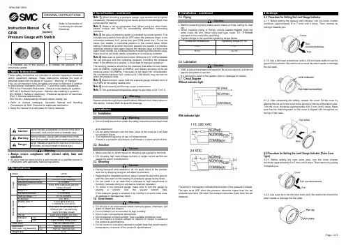
Page 1 of 2Instruction ManualGP46Pressure Gauge with Switchis pneumatic system.1 Safety InstructionsThese safety instructions are intended to prevent hazardous situations and/or equipment damage. These instructions indicate the level of potential hazard with the labels of “Caution,” “Warning” or “Danger.” They are all important notes for safety and must be followed in addition to International Standards (ISO/IEC) *1), and other safety regulations. *1)ISO 4414: Pneumatic fluid power - General rules relating to systems. ISO 4413: Hydraulic fluid power - General rules relating to systems.IEC 60204-1: Safety of machinery - Electrical equipment of machines. (Part 1: General requirements)ISO 10218-1: Manipulating industrial robots -Safety. etc.• Refer to product catalogue, Operation Manual and Handling Precautions for SMC Products for additional information. • Keep this manual in a safe place for future reference.not avoided, will result in death or serious injury.Warning• Always ensure compliance with relevant safety laws and standards.• All work must be carried out in a safe manner by a qualified person in compliance with applicable national regulations.2 Specifications2 Specification - continuedNote 1) When mounting a pressure gauge, use caution not to tighten excessively. Excessive tightening will cause product to be damaged. Use a pipe tape for sealing.Note 2) Water is not an acceptable fluid. When using the other fluids, please consult with SMC for compatibility information concerning corrosion.Note 3) Set value of pressure switch is indicated by pointer (green). This indicates the position from ON to OFF when the pressure drops in the connection between N.O. (white line) and COM (black line). To set the value, turn needle in clockwise position to the correct value. When setting; if desired set position has been passed, turn needle in a counter-clockwise direction back again beyond the desired value and then once again return needle in a clockwise direction stopping at the desired value. Value must be set while needle is traveling in a clockwise direction. Note 4) Make sure to provide a minimum difference of 0.1 MPa between the set pressure and the operating pressure (including the pressure drop). If the difference is smaller, it could lead to improper operation. The working pressure should be the pressure that adds the set needle error (0.03MPa), hysteresis (0.07MPa), and display accuracy of the set pressure value (±0.05MPa). If accuracy is not taken into consideration, the connection between N.O. (white) and COM (black) may not turn on when the pressure rises.Note 5) Maximum error value: Add the pressure gauge indicator error of 0.03 MPa to the setting needle error.Note 6) Avoid freezing as this may cause a malfunction.Note 7) The guaranteed temperature range for accuracy is 23°C ±5°C.WarningSpecial products might have specifications different from those shown in this section. Contact SMC for specific drawings.3 Installation3.1 InstallationWarning• Do not install the product unless the safety instructions have been readand understood.• Do not apply pressure over the max. value of the scale as it will lead to operation failure.• The maximum frequency of use is 6 times/minute.If there is a pulsation of pressure, it will break in a short period of time.3.2 SelectionCaution• Make sure that no direct impact or vibrations are applied to the body. • Do not apply high load voltage (current) or surge current as this can cause the switch to malfunction. 3.3 MountingCaution• During transport and installation, do not apply shock to the product, such as by dropping doing so will affect its precision.• Regarding the installation posture, place it perpendicular to the ground, with the zero point on the reading of a pressure gauge facing down. • Do not install it in an area that is exposed to high temperature or humidity, because doing so will lead to improper operation.• To screw in the pressure gauge, make sure to turn the gauge by placing a wrench over the square wrench flats. If the pressure gauge is screwed in by holding it on some other area, air leakage or damage may result. 3.4 EnvironmentWarning• Do not use in an environment where corrosive gases, chemicals, salt water or steam are present.• Do not install in an environment of high humidity. • Do not use in an explosive atmosphere.• Do not expose to direct sunlight. Use a suitable protective cover.• Do not install in a location subject to vibration or impact in excess of the product’s specifications .• Do not mount in a location exposed to radiant heat that would result in temperatures in excess of the product’s specifications.3 Installation - continued3.5 PipingCaution• Before connecting piping make sure to clean up chips, cutting oil, dust etc.• When installing piping or fittings, ensure sealant material does not enter inside the port. When using seal tape, leave 1.5 - 2 threads exposed on the end of the pipe/fitting.3.6 LubricationCaution• SMC products have been lubricated for life at manufacture, and do not require lubrication in service.• If a lubricant is used in the system, refer to catalogue for details. 3.7 Circuit Diagram Without indicator lightWith indicator lightThe arrow in the diagram indicates the direction of the pressure increase. The light turns OFF when the pressure becomes higher than the set pressure and turns ON when the pressure becomes lower than the set pressure.4 Settings4..1 Procedure for Setting the Limit Gauge Indicator4.1.1. Before setting the (green) limit indicator, turn the cover counter clockwise (approximately 6 to 7 mm) until it stops. Then, remove by pulling it towards you.4.1.2. Use a flat head screwdriver (with a 2.9 mm blade width) to set the (green) limit indicator. Be careful not to bend the other needle or damage the dial plate.4.1.3. After completing the setting, replace the cover. Fit the cover by aligning the cut out in the cover to the groove on the top of the black case. Turn the cover clockwise (approximately 6 to 7 mm) until it stops. Make sure that the matching mark on the cover is aligned with the groove on the top of the case.4.2 Procedure for Setting the Limit Gauge Indicator (Color Zone Type)4.2.1. Before setting the color zone (red), turn the cover counter clockwise (approximately 6 to 7 mm) until it stops. Then remove by pulling it towards you.4.2.2. Use a pen tip to set the color zone (red). Be careful not to bend the other needle or damage the dial plate.ORIGINAL INSTRUCTIONSRefer to Declaration of Conformity for relevant Directives[option]4.2.3. After completing the setting, replace the cover. Fit the cover by aligning the cut out in the cover to the groove on the top of the black case. Turn the cover clockwise (approximately 6 to 7 mm) until it stops. Make sure that the matching mark on the cover is aligned with the groove on the top of the case.4.3 Procedure for Setting the Limit Gauge Indicator and the Setting Needle4.3.1. Before setting the limit indicator and the (green) setting needle, turn the cover counterclockwise (approximately 6 to 7 mm) until it stops. Then, remove by pulling it towards you.4.3.2. Use a flat head screwdriver (with a 2.9 mm blade width) to set the (green) limit indicator. Be careful not to bend the other needle or damage the dial plate.4.3.3. Before setting the setting needle, use a flat head screwdriver (witha 2.9 mm blade width) to turn the setting screw and set the setting needle to the set pressure.4.3.4. After completing the setting, replace the cover. Fit the cover by aligning the cut out in the cover to the groove on the top of the black case. Turn the cover clockwise (approximately 6 to 7 mm) until it stops. Make sure that the matching mark on the cover is aligned with the groove on the top of the case. 4.4 Procedure for Assembling the Cover Ring Assembly •Pressure gauge for general purpose•Pressure gauge with switch1. Remove the small screw (1 position) from the pressure gauge.2. Place the cover ring on the pressure gauge.3. Using the small screw that is provided with the cover ring, install the cover ring. The installation torque is 0.6 to 0.7 N・m. However, when reassembling, it shall be 0.5 to 0.6 N・m.5 How to OrderRefer to drawings or catalogue for ‘How to Order’.6 Outline Dimensions (mm)Refer to drawings or catalogue for outline dimensions.7 Maintenance7.1 General MaintenanceCaution•Not following proper maintenance procedures could cause the productto malfunction and lead to equipment damage.•If handled improperly, compressed air can be dangerous.•Maintenance of pneumaticsystems should be performedonly byqualified personnel.•Before performing maintenance, turn off the power supply and be sureto cutoff the supply pressure. Confirm that the air is released toatmosphere.•After installation and maintenance, apply operating pressure andpower to the equipment and perform appropriate functional andleakage tests to make sure the equipment is installed correctly.•If any electrical connections are disturbed during maintenance, ensurethey are reconnected correctly, and safety checks are carried out asrequired to ensure continued compliance with applicable nationalregulations.•Do not make any modification to the product.•Do not disassemble the product, unless required by installation ormaintenance instructions.8 Limitations of Use8.1 Limited warranty and Disclaimer/Compliance RequirementsRefer to Handling Precautions for SMC Products.9 Product disposalThis product should not be disposed of as municipal waste. Check yourlocal regulations and guidelines to dispose this product correctly, in orderto reduce the impact on human health and the environment.10 ContactsRefer to or www.smc.eu for contacts.URL : http// (Global) http// www.smc.eu (Europe)'SMC Corporation, Akihabara UDX15F, 4-14-1, Sotokanda, Chiyoda-ku, Tokyo 1010021Specifications are subject to change without prior notice from the manufacturer.© 2020 SMC Corporation All Rights Reserved.Template DKP50047-F-085JPage 2 of 2。
smc数显压力表设定方法SMC数显压力表设定方法。
SMC数显压力表是一种常用的压力测量仪器,它可以直观地显示当前的压力数值,并且具有一定的设定功能,可以根据需要进行压力设定。
接下来,我们将介绍SMC数显压力表的设定方法,希望能够帮助您正确、方便地使用这一设备。
首先,确保您已经熟悉了SMC数显压力表的基本结构和功能,了解了各个按钮和显示屏的作用。
在进行设定之前,需要对设备进行基本的检查,确保其正常工作。
然后,按照以下步骤进行设定:1. 调整显示屏。
打开SMC数显压力表的电源开关,观察显示屏上的数值是否正常显示。
如果显示不清晰或有异常情况,需要及时进行调整或维修。
2. 进入设定模式。
根据设备说明书,找到进入设定模式的方法。
通常情况下,需要按下特定的按钮组合或者进行长按操作,使设备进入设定状态。
3. 设置压力单位。
在设定模式下,可以选择所需的压力单位,例如MPa、bar、psi等。
通过操作按钮,选择合适的单位并确认。
4. 设定目标压力值。
根据实际需求,设定所需的目标压力数值。
通过操作按钮,逐位输入数字,并确认每一位数字的输入,直至完成整个数值的设定。
5. 确认设定。
在设定完成后,需要进行确认操作,使设备保存并生效所设定的压力数值。
确认操作通常是按下确认按钮或者按下特定组合的按钮。
6. 退出设定模式。
设定完成后,需要退出设定模式,使设备回到正常的工作状态。
按照设备说明书的要求,进行相应的退出操作。
7. 检查设定结果。
设定完成后,可以再次观察显示屏上的压力数值,确认设定是否成功。
如果有异常情况,需要重新进行设定操作。
总结。
通过以上步骤,您可以完成SMC数显压力表的设定操作。
在进行设定时,需要仔细阅读设备说明书,按照要求进行操作,确保设定的准确性和有效性。
同时,在使用过程中,需要注意设备的工作状态和显示情况,及时发现并解决问题,保证设备的正常运行和使用效果。
希望以上内容能够帮助您正确、方便地使用SMC数显压力表,如果在使用过程中遇到问题,可以随时联系我们的客服人员,我们将竭诚为您提供帮助。
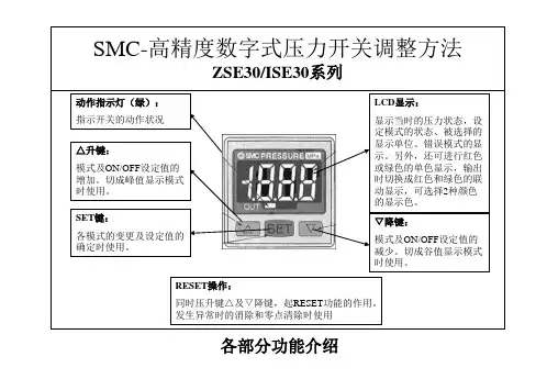
文件No.PS※※-OMS0006CN-G数字式压力开关ZSE20(F)ISE20安全注意事项2型式表示・型号体系8产品各部位名称及功能10用语说明11安装·设置14设置方法14配管方法16配线方法18设定概要[测量模式] 20 压力设定21 3步设定模式22 简易设定模式24功能选择模式26功能选择模式说明26出厂设定26 F0 单位切换功能28 F1 OUT1的设定29 F3 数字滤波器的设定32 F4 自动预设功能的设定33 F6 显示值微调的设定35 F10 子画面的设定36 F11 显示分辨率的设定41 F80 省电模式的设定42 F81 密码输入的设定43 F82 线名输入的设定45 F90 全功能的设定46 F98 输出确认48 F99 恢复出厂设置49其他设定50维护54忘记密码的场合54故障一览表55规格62规格表62外形尺寸图64安全注意事项此处所示的注意事项是为了确保您能安全正确地使用本产品,预先防止对您和他人造成危害和伤害而制定的。
这些注意事项,按照危害和损伤的大小及紧急程度分为「注意」「警告」「危险」三个等级。
无论哪个等级都是与安全相关的重要内容,所以除了遵守国际规格(ISO/IEC)、日本工业规格(JIS)*1)以及其他安全法规*2)外,这些内容也请务必遵守。*1) ISO 4414: Pneumatic fluid power -- General rules relating to systemsISO 4413: Hydraulic fluid power -- General rules relating to systemsIEC 60204-1: Safety of machinery -- Electrical equipment of machines (Part 1: General requirements)ISO 10218: Manipulating industrial robots-SafetyJIS B 8370: 空气压系统通则JIS B 8361: 油压系统通则JIS B 9960-1: 机械类的安全性-机械的电气装置(第1部:一般要求事项)JIS B 8433: 产业用操作机器人-安全性等*2) 劳动安全卫生法等注意误操作时,有人员受伤的风险以及物品破损的风险。警告误操作时,有人员受到重大伤害甚至死亡的风险。
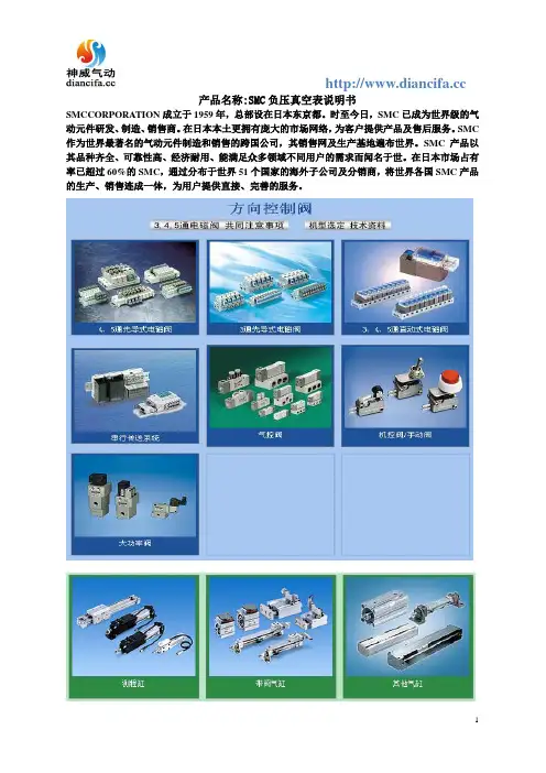
产品名称:SMC负压真空表说明书
SMCCORPORATION成立于1959年,总部设在日本东京都。
时至今日,SMC已成为世界级的气动元件研发、制造、销售商。
在日本本土更拥有庞大的市场网络,为客户提供产品及售后服务。
SMC 作为世界最著名的气动元件制造和销售的跨国公司,其销售网及生产基地遍布世界。
SMC产品以其品种齐全、可靠性高、经济耐用、能满足众多领域不同用户的需求而闻名于世。
在日本市场占有率已超过60%的SMC,通过分布于世界51个国家的海外子公司及分销商,将世界各国SMC产品的生产、销售连成一体,为用户提供直接、完善的服务。

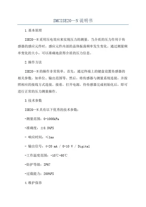
SMCISE20—N说明书1.基本原理ISE20—N采用压电效应来实现压力的测量。
当介质的压力作用于传感器的感应元件时,感应元件内部的晶体振荡频率发生变化。
通过测量频率变化的大小,可以准确地获得介质的压力信息。
2.操作方法ISE20—N的操作非常简单。
首先,通过终端上的键盘设置传感器的相关参数,如单位、输出范围等。
然后,将传感器与测量系统连接,并按照相应的接线方式连接。
接着,打开电源,待传感器完成初始化后,即可进行正常的压力测量操作。
3.技术参数ISE20—N具有以下优秀的技术参数:-测量范围:0-1000kPa-准确度:±0.5%FS- 响应时间:≤1ms- 输出信号:4-20 mA / 0-10 V / Digital-工作温度范围:-10℃-60℃-防护等级:IP67-过载能力:200%FS4.维护保养为确保ISE20—N的正常工作和延长使用寿命,需要进行定期的维护保养。
具体的维护保养事项包括:-定期清洁传感器的外壳,避免灰尘和污垢对传感器的影响;-检查传感器的接线是否松动,确保传感器与测量系统的正常连接;-定期校准传感器的测量精度,以确保其准确性和稳定性。
5.应用领域ISE20—N广泛应用于工业自动化和控制系统中的压力测量。
它适用于各种介质的压力监测和控制,如液体、气体、蒸汽等。
其高精度、高性能的特点,使得它在化工、食品加工、机械制造等行业中得到了广泛的应用。
总结:SMCISE20—N是一种高精度、高性能的数字压力传感器,具有广泛的应用领域和优越的性能特点。
本说明书详细介绍了ISE20—N的基本原理、操作方法、技术参数以及维护保养等方面的内容。
希望本说明书能够帮助用户更好地了解和使用ISE20—N,从而满足其在压力测量和控制领域的需求。
真空表操作手册1. 简介真空表是一种用于测量、监测和控制系统内真空程度的仪器。
本操作手册旨在帮助用户正确操作真空表,保证准确测量和长期稳定的使用。
2. 准备工作在开始操作真空表之前,请确保以下准备工作已完成:- 将真空表放置于稳定的工作平台上,并保持平衡。
- 确认真空表与真空系统的连接管道已正确连接,并且密封良好。
- 打开真空系统的主控开关。
3. 操作步骤步骤一:打开电源在使用真空表之前,需要先打开电源。
确保电源线已正确连接,并按下电源开关。
步骤二:选择测量模式真空表通常具有多种测量模式,如绝压模式、相对压模式等。
根据需要选择合适的测量模式,并在屏幕上进行设置。
步骤三:零点校准在进行测量之前,进行零点校准以保证测量的准确性。
按照真空表的说明书进行校准操作,并等待校准完成。
步骤四:开始测量待真空表校准完成后,将探头放入要测量的空间中。
确保探头与空间的接触良好,并等待一段时间以稳定测量结果。
步骤五:记录测量结果当真空表显示出稳定的测量结果后,将结果记录下来。
可以使用纸质表格或电子表格进行记录,以便后续分析和比较。
4. 维护与注意事项为确保真空表的正常使用和精确测量,需要注意以下事项:- 定期清洁真空表的探头,并保持其表面清洁。
- 避免将真空表暴露于高温、高湿等恶劣环境中。
- 避免碰撞或震动真空表,以防损坏。
5. 故障排除如果在使用真空表时遇到问题,可以参考以下故障排除方法:- 检查电源线是否正确连接,并确认电源是否正常供电。
- 检查真空表与真空系统的连接情况,确保连接处没有泄漏。
- 根据真空表的说明书,查看是否存在其他故障排除方法。
6. 总结本操作手册提供了关于真空表的操作步骤、维护和故障排除等内容。
请用户在操作真空表时,严格按照手册的指导进行,以确保测量结果的准确和真空表的长期稳定使用。
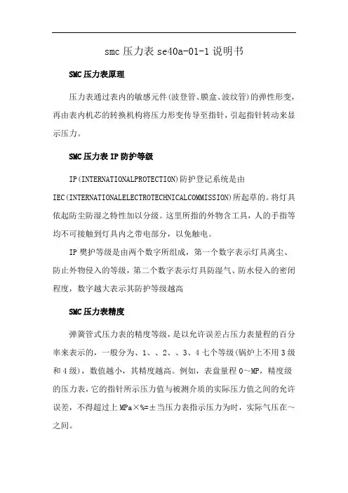
smc压力表se40a-01-1说明书SMC压力表原理压力表通过表内的敏感元件(波登管、膜盒、波纹管)的弹性形变,再由表内机芯的转换机构将压力形变传导至指针,引起指针转动来显示压力。
SMC压力表IP防护等级IP(INTERNATIONALPROTECTION)防护登记系统是由IEC(INTERNATIONALELECTROTECHNICALCOMMISSION)所起草的。
将灯具依起防尘防湿之特性加以分级。
这里所指的外物含工具,人的手指等均不可接触到灯具内之带电部分,以免触电。
IP樊护等级是由两个数字所组成,第一个数字表示灯具离尘、防止外物侵入的等级,第二个数字表示灯具防湿气、防水侵入的密闭程度,数字越大表示其防护等级越高SMC压力表精度弹簧管式压力表的精度等级,是以允许误差占压力表量程的百分率来表示的,一般分为、1、、2、、3、4七个等级(锅炉上不用3级和4级),数值越小,其精度越高。
例如,表盘量程0~MP,精度级的压力表,它的指针所示压力值与被测介质的实际压力值之间的允许误差,不得超过上MPa×%=±当压力表指示压力为时,实际气压在~之间。
SMC压力表详解:1.安装压力表的部位(除与锅筒蒸汽空间直接相连接处必须安装压力表外)(1)给水调节阀前。
(2)可分式省煤器出口。
(3)过热器出口和主汽阀之间。
(4)再热器出、入口。
(5)直流锅炉启动分离器。
(6)直流锅炉一次汽水系统的阀门前。
(7)强制循环锅炉锅水循环泵出、入口。
(8)燃油锅炉油泵进、出口。
(9)燃气锅炉的气源人口。
2.选用压力表的规定(1)对于额定蒸汽压力小于MPa的锅炉,压力表精确度不应低于级;对于额定蒸汽压力大于或等于MPa的锅炉,压力表的精确度不应低于级。
(2)压力表应根据工作压力选用。
压力表表盘刻度极限值应为工作压力的~倍,最好选用2倍。
(3)压力表表盘大小应保证司炉人员能清楚地看到压力指示值,表盘直径不应小于100mm。
,显示屏显示为一丁匚]Z/ISE30A 系列压力开关设定说明设定顺序:通电一测量模式一零点校正一功能设定一测量模式产品通电后,自动进入压力测量模式,第一次使用时,请按如下顺序操作。
1、零点校正:产品第一次使用时, 通电且不施加气压时, 如果显示值不为零, 三和卫 键同时按住1s 以上,显示值归零。
2、基本功能设定:测量模式下按住[室[键2s 以上,压力开关进入功能设定模式 按;和【旦 键选择对应功能后按[玄 进入详细功能设置。
测量模式按住2s 以上备注:部分功能为可选功能,根据型号而定。
特定型号下如果不包含某可选功能, 对应位置显示卜…I 。
全部功能列表:F1 : 0UT1规格设定 迟滞模式,常开 F2 : 0UT2规格设定 迟滞模式,常开F3 :响应时间设定 2.5 msF4 :显示精度设疋 1/1000F5 :自动预设功能设定 手动模式F6 :显示值校正 0%F7 :省电模式选择OFFF8 :密码锁设定 OFF1 ) F0-单位选择功能可选功能,部分型号无此功能。
单位不同,显示屏开显示的数值范围不同。
操作方法:按“和卫_键选择对应单位,按 ■事键确认。
F0-单位选择功能设定完成2)F1-0UT1输出规格设定方法:此部分可设置输出类别(迟滞型 /比较型)和输出模式(常开 /常闭)设定。
按!三键进入单位选择模式I按!爭键完成设定返回到功能选择模式,屏幕显示 F0迟滞模式(岀厂时默认设置)常开型 常闭型比较模式(也称窗口比较模式)迟滞(H1) 迟滞(H1)ON OFF功能选择模式下按 输出 ON OFF迟滞(H-1) K ---------- 厂一…一P-1压力k比较模式(也称窗口比较模式)输出n1L和卫_至屏幕显示I ■ ' I ,然后按进入OUT1规格设定。
输出模式岀厂时默认设置输出迟滞(H1)迟滞( H1)ON OFF1 _>1 <、 «:」 TkI~~1 +AP1L P1H压力h迟滞模式(岀厂时默认设置)输出 ON 1迟滞(H-1) iL -----------{ OFF----------------------n 1 压力按S 键进入0UT1规格设定压力设定状态:此状态下设定压力开关输出的 ON/OFF 点。
Z/ISE30A 系列压力开关设定说明设定顺序:通电—测量模式—零点校正—功能设定—测量模式产品通电后,自动进入压力测量模式,第一次使用时,请按如下顺序操作。
1、零点校正:产品第一次使用时,通电且不施加气压时,如果显示值不为零,和键同时按住1s 以上,显示值归零。
2、基本功能设定:测量模式下按住键2s 以上,压力开关进入功能设定模式,显示屏显示为。
按和键选择对应功能后按进入详细功能设置。
备注:部分功能为可选功能,根据型号而定。
特定型号下如果不包含某可选功能,对应位置显示。
全部功能列表:测量模式按住键2s 以上功 能 选 择 模 式功能设定1)F0-单位选择功能可选功能,部分型号无此功能。
单位不同,显示屏开显示的数值范围不同。
操作方法:按和键选择对应单位,按键确认。
2)F1-OUT1输出规格设定方法:此部分可设置输出类别(迟滞型/比较型)和输出模式(常开/常闭)设定。
按键进入单位选择模式按和键选择对应单位交替显示按键完成设定返回到功能选择模式,屏幕显示F0F0-单位选择功能设定完成输出模式常开型出厂时默认设置常闭型迟滞模式(出厂时默认设置)压力输出迟滞(H-1)压力输出压力输出迟滞(H-1)压力输出比较模式(也称窗口比较模式)迟滞模式(出厂时默认设置)比较模式(也称窗口比较模式)迟滞(H1)迟滞(H1)迟滞(H1)迟滞(H1)功能选择模式下按和至屏幕显示,然后按进入OUT1规格设定。
压力设定状态:此状态下设定压力开关输出的ON/OFF 点。
以迟滞型为例:输出方法:当压力超过设定值时,开关输出变为ON 。
当压力下降到设定值-迟滞(参见下图)以下时,开关输出变为OFF 。
按键 进入OUT1规格设定设定输出类别-迟滞型/比较型 按和选择对应模式。
按确认交替显示输出类别设定值迟滞型 比较型设定输出模式-常开模式/常闭模式 按和选择常开/常闭。
按确认交替显示输出模式设定值常开型 常闭型按键确认 进入压力设定状态按键 进入输出模式设定<操作方法>1、 压力设定状态进入方法 (1) 如上所述。
Other SettingsSummary of Product partsSimple Setting ModeTroubleshootingNote: Specifications are subject to change without prior notice and any obligation on the part of the manufacturer.© 2020 SMC Corporation All Rights ReservedAkihabara UDX 15F, 4-14-1, Sotokanda, Chiyoda-ku, Tokyo 101-0021, JAPANPhone: +81 3-5207-8249 Fax: +81 3-5298-5362URL https://Specifications/Outline with DimensionsRefer to the product catalog or SMC website (URL https://) for moreinformation about the product specifications and outline dimensions.PS※※-OMX0003 DC(+)OUT1NCNCDC(-)BrownBlackWhiteGrayBlueDefault settingsWhen the pressure exceeds the setvalue, the switch will be turned on.When the pressure falls below theset value by the amount ofhysteresis or more, the switch willbe turned off. The default setting isto turn on the pressure switch whenthe pressure reaches the centre ofthe atmospheric pressure and upper limit of the rated pressure range. If this condition,shown to the right, is acceptable, then keep these settings.Error indication functionThis function is to display error location and content when a problem or error has occurred.above are displayed, please contact SMC.Refer to the SMC website (URL https://) for more information abouttroubleshooting.button between3 and 5 sec.∗:The outputs will continue to operate during setting.∗:If a button operation is not performed for 3 seconds during the setting, the display will flash.(This is to prevent the setting from remaining incomplete if, for instance, an operator were to leave duringsetting.)∗:3 step setting mode, simple setting mode and function selection mode settings are reflected each other.[3 step setting mode (hysteresis mode)]orcan be changed in the same way.button once when the item to beThe set value on the sub display (right) will startflashing.orbutton and can be reduced with button.buttons are pressed and held simultaneously for 1 second orlonger, the set value is displayed as [- - -], and the set value will be the same as thecurrent pressure value automatically (snap shot function).Afterwards, it is possible to adjust the value by pressing button.button to complete the setting.The pressure switch turns on within a set pressure range (from P1L to P1H) duringwindow comparator mode.Set P1L, the lower limit of the switch operation, and P1H, the upper limit of the switchoperation and WH1 (hysteresis) following the instructions given above.(When reversed output is selected, the sub display (left) shows [n1L] and [n1H].)∗:Set OUT2 in the same way. (ex. P_2, H_2)∗:Setting of the normal/reverse output switching and hysteresis/window comparator mode switchingare performed with the function selection mode [F 1] OUT1 setting and [F 2] OUT2 setting.value[F 0] Display units, switch output specificationsand diagnostic information selection functionPeak/bottom value indicationThe value can be displayed on the sub display by pressing button inmeasurement mode.Snap shot functionbuttons for 1 secondor longer simultaneously. Then, the set value of the sub display (right) shows [- - -], andthe values corresponding to the current pressure values are automatically displayed.Zero-clear functionIn measurement mode, when the buttons are pressed for 1 second orlonger simultaneously, the main display shows [- - -], and the reset to zero.The display returns to measurement mode automatically.Key-lock functionTo set each of these functions, refer to the SMC website(URL https://) for more detailed information, or contact SMC.button between 1 and 3 seconds in measurementmode. [SEt] is displayed on the main display. When the button is releasedwhile in the [SEt] display, the current pressure value is displayed on themain display, [P_1] or [n_1] is displayed on the sub display (left), and theset value is displayed on the sub display (right) (Flashing).or button to(The snap shot function can be used.)or button to set the(The snap shot function can be used.)or button, the delay time of the switch output can be selected.button for 2 seconds or longer to complete the setting.∗:If the button is pressed for less than 2 seconds, the setting will moves to the OUT2 setting.In the window comparator mode, set P1L, the lower limit of the switch operation, andP1H, the upper limit of the switch operation, WH1 (hysteresis) and dt1 (delay time)following the instructions given above.(When reversed output is selected, the sub display (left) shows [n1L] and [n1H].)∗:Set OUT2 in the same way.Function selection modebuttonbetween 3 and 5 seconds, to display [F 0].Select to display the function to be changed[F button for 2seconds or longer in function selection modeto return to measurement mode.∗:Some products do not have all the functions. If no functionis available or selected due to configuration of otherfunctions, [- - -] is displayed on the sub display (right).Names of individual partsPressure Setting3 Step Setting Mode(URL https://) for more detailed information, or contact SMC.MaintenanceHow to reset the product after a power cut or forcible de-energizingThe setting of the product will be retained as it was before a power cut or de-energizing.The output condition is also basically recovered to that before a power cut or de-energizing, but may change depending on the operating environment. Therefore, checkthe safety of the whole installation before operating the product. If the installation is usingaccurate control, wait until the product has warmed up (approximately 10 to 15 minutes). Safety InstructionsBefore UseDigital Pressure SwitchZSE20C(F)-L/ISE20C(H)-LThank you for purchasing an SMC ZSE20C(F)-L/ISE20C(H)-L Series Digital PressureSwitch.Please read this manual carefully before operating the product and make sure youunderstand its capabilities and limitations. Please keep this manual handy for futurereference.Safety InstructionsThese safety instructions are intended to prevent hazardous situations and/orequipment damage.These instructions indicate the level of potential hazard with the labels of "Caution","Warning" or "Danger". They are all important notes for safety and must be followed inaddition to International standards (ISO/IEC) and other safety regulations.OperatorSwitch ONAt normal output Switch OFFSet valueP_1HysteresisH_1TimePressureDefault settingThe default setting is as follows.If no problem is caused by this setting,keep these settings.[F 1] Setting of OUT1[F 2] Setting of OUT2Same setting as [F 1] OUT1.InstallationMountingMount the optional bracket and panel mount adapter to the pressure switch.When the pressure switch is to be mounted in a place where water and dustsplashes occur, insert a tube into the air-relieving port of the pressure switch.(Refer to "Tube attachment")Mounting with bracketMount the bracket to the body with mounting screws(Self tapping screws), then set the body to the specified position.∗: Tighten the bracket mounting screws to a torque of 0.5±0.05 Nm.Self tapping screws are used, and should not be re-used several times.∗•Bracket A (Part No.: ZS-46-A1)•Bracket C (Part No.: ZS-46-E)<Rear piping><Bottom piping>WiringWiring connectionsConnections should be made with the power supply turned off.Use a separate route for the product wiring and any power or high voltage wiring.Otherwise, malfunction may result due to noise.If a commercially available switching power supply is used, be sure to ground theframe ground (FG) terminal. If the switching power supply is connected for use,switching noise will be superimposed and it will not be able to meet the productspecifications. In that case, insert a noise filter such as a line noise filter/ferritebetween the switching power supplies or change the switching power supply toHow to use connectorConnection using screw type fittingConnect suitable piping to the port.To connect the hexagon socket head plug or fitting to thepressure port, hold the hexagon part of the pressure port with asuitable spanner. Apply atightening torque of 8 to12 Nm.When tightening, do nothold the pressure switchbody with a spanner.Tube attachmentWhen this pressure switch is used in a place where water and dust splashes mayoccur, insert a tube in the air-opposite side up to the safe positionto keep it from water and dust.(See the right figure.)∗: The tube should be inserted to the end ofthe air-relieving port.∗: SMC TU0425 (polyurethane, O.D ø4, I.Dø2.5) is a suitable tubing.To the safe position to keep from water and dust。
smc数显压力表设定方法SMC数显压力表设定方法。
SMC数显压力表是一种常用的压力测量仪器,广泛应用于工业领域。
正确的设定方法可以确保其准确度和稳定性,提高工作效率。
下面将介绍SMC数显压力表的设定方法,希望能对您有所帮助。
首先,确保SMC数显压力表的电源已接通,并且压力表已经连接到相应的管路上。
接下来,按照以下步骤进行设定:1. 检查零点。
在设定压力表之前,需要先检查压力表的零点。
将压力表放置在零压力状态下,观察数显屏幕上的数值是否稳定在零。
如果不稳定,需要进行调零操作,确保数显压力表的零点准确。
2. 设定量程。
根据实际测量需求,设定SMC数显压力表的量程。
量程设定是根据被测介质的最大压力来确定的,确保压力表的量程能够满足实际测量需求。
3. 调整显示单位。
SMC数显压力表通常可以显示不同的压力单位,如MPa、bar、psi等。
根据实际需要,选择合适的显示单位,并进行相应的设定。
4. 校准。
在设定完成后,需要进行校准操作。
将压力表连接到标准压力源上,调节压力源输出的压力值,观察数显压力表的显示数值是否与标准值一致。
如果不一致,需要进行校准调整,直到数显压力表的显示数值与标准值一致为止。
5. 确认设定。
在完成上述步骤后,需要再次确认数显压力表的设定是否准确。
可以通过连接到实际工作环境中进行实时测量,验证数显压力表的准确性和稳定性。
总结。
SMC数显压力表的设定方法并不复杂,但需要注意细节和准确性。
正确的设定可以保证压力表的准确度和稳定性,提高工作效率,确保生产安全。
希望以上介绍能够帮助您正确使用SMC数显压力表,并取得满意的测量结果。
SMC表头的设定1.单位的确定a)按中间键“set”2S以上进入“F0~F99”界面。
b)用▲和▼两键选择F0,按中“set”进入单位选择界面。
如下图:进入单位界面c)用▲和▼选择自已想要的单位,表头显示与单位的图画如下:单位界面注:表头不同型号所包含的单位个数也不同。
d)选择好单位,按“set”2S以上即设定好单位,返回了显示界面。
2.a/b接点(常开/常闭)的设定a)按中间键“set”2S以上进入“F0~F99”界面。
b)用▲和▼两键选择F1,按中“set”进入输出类别选择界面。
如下图类别选择界面c)用▲和▼两键选择HY5 ,按“set”确定进入输出模式选择。
输出模式d)用▲和▼两键选择,按“set”确定把表头设为常开或常闭型。
接点选择3.最小值与最大值设定(以常开为例)a)用▲和▼两键选择1-P,按“set”确定进入了最小值设定,如下图:最小值b)加或减小一位,按“set”确定。
c) 最小值设定确定后,就会进入最大值设定。
如下图:最大值d) 用▲和▼两键可以设定最小值,每按▲和▼一次设定值会增加或减小一按“set”确定。
3.标准值的设定当最大值设定后,长按“set”2S以上返回到表头的显示界面。
Ⅰ、正压表头时:———打开调压阀开关把气压值调至到标准值。
Ⅱ、负压表头时:a)把负压的吸嘴外放上产品。
b)打开真空产生器。
c)打开调压阀开关把气压值调至到标SMC表头的设定检验用调压阀上的调节开关来调节气压的大小,来检验表头的最大与最小值是否正确。
a)当调节的气压大于最大值或小于最小值时,出现警报,则说明设定正确。
---把气压调回正常值。
表头就可以工作使用。
b)当调节的气压大于最大值或小于最小值时,不出现警报,则说明设定错误。
---表头需要检查重新设定。
注:如是负压表头:要把负压的吸嘴外放上产品并打开真空产生器。
才能按上面步骤检验。
Z/ISE30A 系列压力开关设定说明设定顺序:通电—测量模式—零点校正—功能设定—测量模式产品通电后,自动进入压力测量模式,第一次使用时,请按如下顺序操作。
1、零点校正:产品第一次使用时,通电且不施加气压时,如果显示值不为零,和键同时按住1s 以上,显示值归零。
2、基本功能设定:测量模式下按住键2s 以上,压力开关进入功能设定模式,显示屏显示为。
按和键选择对应功能后按进入详细功能设置。
备注:部分功能为可选功能,根据型号而定。
特定型号下如果不包含某可选功能,对应位置显示。
全部功能列表:项目出厂设置F0:单位选择功能 ISE-Mpa,ZSE-KPa,Option P-psi F1:OUT1规格设定 迟滞模式,常开F2:OUT2规格设定 迟滞模式,常开 F3:响应时间设定 2.5 ms F4:显示精度设定 1/1000 F5:自动预设功能设定 手动模式F6:显示值校正 0% F7:省电模式选择 OFF F8:密码锁设定OFF1)F0-单位选择功能可选功能,部分型号无此功能。
单位不同,显示屏开显示的数值范围不同。
操作方法:按和键选择对应单位,按键确认。
测量模式按住键2s 以上功 能 选 择 模 式功能设定2)F1-OUT1输出规格设定方法:此部分可设置输出类别(迟滞型/比较型)和输出模式(常开/常闭)设定。
按键进入单位选择模式按和键选择对应单位交替显示按键完成设定返回到功能选择模式,屏幕显示F0F0-单位选择功能设定完成输出模式常开型 出厂时默认设置常闭型迟滞模式(出厂时默认设置) 压力输出迟滞(H-1)压力输出压力输出迟滞(H-1)压力输出比较模式(也称窗口比较模式) 迟滞模式(出厂时默认设置) 比较模式(也称窗口比较模式) 迟滞(H1) 迟滞(H1)迟滞(H1) 迟滞(H1)功能选择模式下按和至屏幕显示,然后按进入OUT1规格设定。
压力设定状态:此状态下设定压力开关输出的ON/OFF 点。
以迟滞型为例:输出方法:当压力超过设定值时,开关输出变为ON 。
当压力下降到设定值-迟滞(参见下图)以下时,开关输出变为OFF 。
按键进入OUT1规格设定设定输出类别-迟滞型/比较型 按和选择对应模式。
按确认交替显示输出类别设定值迟滞型比较型设定输出模式-常开模式/常闭模式 按和选择常开/常闭。
按确认交替显示输出模式设定值常开型 常闭型按键确认进入压力设定状态按键进入输出模式设定<操作方法>1、 压力设定状态进入方法 (1) 如上所述。
(2) 设定压力开关通电后自动进入测定模式。
测定模式下按键一次,进入压力设定状态。
2、 压力设定状态下,和设定值在屏幕上交替显示。
【注:为迟滞型常开输出模式时显示,迟滞型常闭输出模式时屏幕显示为; 比较型常开输出模式时显示(P1L ,P1H ),比较型常闭输出模式时屏幕显示为(n1L,n1H ).】3、 按或可以更改设定值。
每按一次键,设定值增加一位。
长按键,设定值可持续增加。
每按一次键,设定值增加一位。
长按键,设定值可持续增加。
4、调好设定值后按键确定,进入迟滞设定。
5、按或可以更改设定迟滞值,按键确定,进入显示颜色设定。
6、3)、F2- OUT2输出规格设定:如果是两输出规格,请重复上述操作以完成OUT2设定。
按键确认进入显示颜色设定迟滞设定: 按和选择要设定的迟滞值,按确认交替显示显示颜色设定值显示颜色设定: 按和选择显示颜色模式,按确认按键确认返回功能选择模式交替显示迟滞设定值F1-OUT1输出规格设定完成4)、F3-响应时间设定:功能设定模式下选择F3,按进入响应时间设定。
5)、F4-显示精度设定:调整显示精度,用于消除末尾显示值跳动。
功能设定模式下选择F4,按进入显示精度设定。
按键进入响应时间设定响应时间设定: 按和选择响应时间值,按确认交替显示响应时间设定值按键确认返回功能选择模式F3-响应时间设定完成按键进入显示精度设定显示精度设定: 按和选择显示精度,按确认交替显示显示精度设定值按键确认返回功能选择模式F4-显示精度设定完成6)、F5-自动预置功能设定:此功能可在试运行条件下自动记录开关输出压力值。
功能设定模式下选择F5,按进入自动预置功能设定。
自动预置操作方法:1、 当F5-自动预置功能选择为“ON ”(automatic )时,在测量模式下按键,进入自动预置状态,此时,屏幕显示“AP1”(对应OUT1)。
2、 再按键,屏幕显示“A1L ”,此时,让压力开关所在系统作动若干个循环,压力开关会自动记录压力变化并计算出最优的开关输出压力设定值,完成设定后屏幕显示“A2L ”。
3、 再按键进入“AP2”(对应OUT2)设定,设定方法同上。
4、 如果AP1或AP2无需自动预置,可同时按下和 1秒钟以上即可跳过。
7)、F6-显示值微调:此功能允许微调压力开关的当前显示值,调整范围为当前显示值的±5%功能设定模式下选择F6,按进入显示值微调。
自动预置功能设定: 按和选择自动预置功能状态, 按确认交替显示自动预置设定值按键确认返回功能选择模式F5-自动预置功能设定完成显示值微调:按和微调显示值,按确认;屏幕将交替显示[FSC]和调整比例(微调变化量与微调前显示值的比值)。
交替显示显示值微调设定值按键确认返回功能选择模式F6-显示值微调完成当屏幕显示[FSC]时,同时按下和键 1秒钟以上,微调值将被初始化(出厂设置)。
按键确认交替显示显示值微调 调整比例8)、F7-省电模式设定:省电模式下,当压力开关30s 无操作时,将会进入省电模式。
此时屏幕无显示,只有三个亮点闪烁。
按任意键可使屏幕显示当前压力值。
功能设定模式下选择F7,按进入省电模式设定。
9)、密码锁设定:此功能允许您在锁定键盘时追加密码,无此密码则无法解开键盘锁。
功能设定模式下选择F8,按进入密码锁设定。
密码更改方法参见第11页。
省电模式设定: 按和选择省电模式打开或关闭, 按确认;交替显示省电模式设定值按键确认返回功能选择模式F7-省电模式设定完成密码锁设定: 按和选择密码锁功能打开或关闭, 按确认;交替显示密码锁设定值按键确认返回功能选择模式F8-密码锁设定完成3、特殊功能设定部分 1)、F90-全部功能设定:全部功能可连续设定,无需每次都返回主菜单。
功能设定模式下选择F90,按进入全部功能设定。
2)、F97-复制功能:当压力开关的压力单位,对应压力范围相同时,一个压力开关中的压力、功能设定(不包括压力显示值微调)可被复制到其它压力开关中。
配线方法:关闭电源,将压力开关用专用线缆连接起来。
主压力开关为要复制的压力、功能设置数据的来源,是被复制对象; 从压力开关为压力、功能设置数据要复制到的目的地。
全部功能设定: 按和选择功能,按确认。
交替显示全部功能 设定值按下键2秒钟以上选择“OFF ”时 F8-密码锁设定完成选择“ON ”时设置每项功能按键设定返回功能选择模式测量模式变更为“OFF 后,”按键设定返回功能选择模式主压力开关从压力开关12N (N 最大为10)操作方法:在主压力开关的功能设定模式下选择F97,按进入复制功能设定。
复制功能设定:按和选择复制功能打开或关闭,按确认;交替显示复制功能设定值按键确认进入“复制准备”状态,即使断电也能保持按键开始复制主压力开关从压力开关发送/接收复制完成交替显示交替显示闪烁红色闪烁绿色按键可继续执行复制,“复制准备”状态即使断电也能保持同时按下和键1秒钟以上按键复制完成后,同时按下和键1秒钟以上F97-复制功能完成3)、F98-输出检查:此功能下可自由设定压力开关的输出状态,以确认输出是否正常。
在功能设定模式下选择F98,按进入输出检查。
F98-输出检查完成输出检查: 按和选择输出检查打开或关闭交替显示输出检查 设定值常规输出强制输出如果选择 A-常规输出 按键设定 返回功能 选择模式如果选择F-强制输出按键设定OUT1检查: 按和选择OUT1状态交替显示OUT1检查设定值强制OFF 强制ON如果有OUT2, 按键设定, 设定方法同上。
设定完成后按住键2秒钟以上,返回测量模式。
如果无OUT2, 将输出检查部分恢复为A-常规输出后, 按键设定。
返回功能选择 模式测量模式114)、F99-恢复出厂设置:用此功能将所有设置恢复为出厂设置。
在功能设定模式下选择F99,按进入恢复出厂设置。
4、其它辅助功能1)、峰值/谷值显示:此功能可以显示压力开关从通电时起至当前时刻这段时间内压力开关检测到的最大压力和最小压力值。
峰值显示:按住键1秒钟以上,屏幕开始持续交替显示峰值压力和“Hi ”; 再按住键1秒钟以上,压力开关返回测量模式。
谷值显示:按住键1秒钟以上,屏幕开始持续交替显示谷值压力和“Lo ”; 再按住键1秒钟以上,压力开关返回测量模式。
2)、按键锁:此功能可在设定完成后将按键锁定,防止误操作。
操作方法:测量模式下,按住键5秒钟以上,直至屏幕显示当前按键锁定状态“LoC ”-锁定或“UnL ”-解锁;按或选择是否锁定按键,按键完成设定。
当按键锁带密码时,操作方法如下:① 按键锁定:按住键5秒钟以上,直至屏幕显示“UnL ”(按键未锁定);按或选择“LoC ”(锁定按键),按键完成按键锁定。
② 按键解锁:按住键5秒钟以上,直至屏幕显示“LoC ”;按或选择“UnL ”,按键确定;此时,屏幕显示如右图,需要输入解锁密码。
③ 如果密码输入正确,屏幕显示“UnL ”,此时按任意键使按键锁解开,屏幕显示返回测量模式。
如果密码输入错误,屏幕显示“FAL ”后返回右图所示界面,要求重新输入密码;如果密码连续3次错误,屏幕显示“LoC ”,按键锁定。
④ 密码修改方法:出厂时出示密码为“000”。
执行上述①②③步至密码输入正确,屏幕显示“UnL ”时,同时按下两键5秒钟以上,直至屏幕显示“000”,此时可修改显示值为您想要的密码。
修改方法如下。
输出检查: 按和选择输出检查打开或关闭交替显示出厂设置 设定值 选择ON 时,所有设置恢复为出厂设置。
返回功能选择模式。
选择OFF 时,按键设定。
返回功能选择模式。
F99-恢复出厂设置完成。