Nepp存储设备安装配置手册
- 格式:docx
- 大小:258.66 KB
- 文档页数:25
Guide d'installation des systèmes de stockage de bureau ReadyNAS OS 6.2Table des matièresContenu de la boîte. . . . . . . . . . . . . . . . . . . . . . . . . . . . . . . . . . . . . 3 Configuration de base . . . . . . . . . . . . . . . . . . . . . . . . . . . . . . . . . . . 4 Reformatage des disques . . . . . . . . . . . . . . . . . . . . . . . . . . . . . . . . 7 Informations supplémentaires . . . . . . . . . . . . . . . . . . . . . . . . . . . . . 9Contenu de la boîteSystème ReadyNASCâble Ethernet Adaptateur secteur et cordond'alimentation(différent selon le modèle) IMPORTANT:lisez tous les avertissements de sécurité du manuel du matériel de votre système avant de brancher ce dernier àl'alimentation.Configuration de baseUne fois que vous aurez suivi ces instructions, le ReadyNAS seraprêt à être utilisé dans un environnement de production. L'installation prend environ 15 minutes.Pour configurer votre système de stockage :1.Installez tous les disques disponibles que vous souhaitez utiliserdans votre système ReadyNAS.Remarque : si vous utilisez des disques déjà formatésauparavant et qui contiennent des données, vous devez lesreformater avant de continuer. Consultez la section Reformatage des disques à la page 7.Consultez la liste de compatibilité matérielle à l'adresse/readynas-hcl pour obtenir une liste des disques pris en charge.Pour obtenir des informations sur l'installation des disques,consultez le manuel du matériel de votre système.2.Placez le système dans un endroit bien ventilé.Les disques de grande capacité produisent une quantité dechaleur considérable. Il est important de s'assurer que la grille de ventilation n'est pas obstruée.Pour consulter la liste complète des aspects à prendre en compte pour le positionnement du système, consultez son manuel dumatériel.3.Branchez le cordon d'alimentation sur l'adaptateur secteur.4.Branchez l'adaptateur secteur à l'arrière du système et le cordond'alimentation à une prise murale ou à un bloc multiprise.5. A l'aide d'un câble Ethernet, connectez un port Ethernet dusystème de stockage à votre réseau.6.Si nécessaire, appuyez sur le bouton d'alimentation pour mettrele système sous tension.7.Attendez que le voyant d'alimentation s'allume en bleu ou quel'écran d'affichage de l'état affiche l'adresse IP du système.8.Visitez le site depuis un ordinateurconnecté au même réseau local (LAN) et disposant de la même connexion Internet que votre système ReadyNAS.si votre ordinateur ne peut pas accéder à Internet, Remarque:installez et exécutez l'utilitaire RAIDar. Téléchargez RAIDar sur un ordinateur connecté à Internet et transférez le fichiertéléchargé à l'ordinateur appartenant au même réseau local que le système ReadyNAS. Vous trouverez la dernière version deRAIDar à l'adresse /raidar.9.Cliquez sur Discover (Découvrir).ReadyCLOUD détecte automatiquement le système ReadyNAS présent sur le réseau.Votre nouveau système ReadyNAS est indiqué par un bandeau NEW (Nouveau).10.Cliquez sur le bouton Setup (Configurer).11.Sélectionnez le mode que vous souhaitez utiliser pour laconfiguration de votre système.•Option 1. Sélectionnez Join Now (Rejoindre maintenant).a Connectez-vous sur ReadyCLOUD ou créez un compteutilisateur.b Suivez les instructions à l'écran pour configurer votresystème ReadyNAS.•Option 2. Sélectionnez Join Later (Rejoindre plus tard).a Saisissez admin comme nom d'utilisateur et passwordcomme mot de passe, puis cliquez sur le bouton OK.vous pouvez modifier ces identifiants lors de la Remarque:configuration de votre système. Il est recommandé demodifier le mot de passe dès que possible.La page d'administration locale ReadyNAS s'affiche dansvotre navigateur et lance un assistant de configuration.b Suivez les instructions de l'assistant de configurationpour configurer votre système ReadyNAS.Le processus de configuration est terminé. Vous pouvez commencer à utiliser votre système de stockage ReadyNAS.Reformatage des disquesSi vous utilisez des disques déjà formatés auparavant et qui contiennent des données, vous devez les reformater pour pouvoir les utiliser avec votre système ReadyNAS.Avertissement : ce processus efface toutes les données et reformate tous les disques pour créer un seul volume X-RAID2. Si vous souhaitez conserver les données présentes sur ces disques, vous devez les sauvegarder sur un lecteur externe avant de les utiliser dans votre système de stockage ReadyNAS.Pour reformater des disques déjà formatés :1.Si votre système est sous tension, mettez-le hors tensionnormalement.Consultez la section Informations supplémentaires à la page 9.2.Installez les disques préalablement formatés.Consultez la liste de compatibilité matérielle à l'adresse/readynas-hcl pour obtenir une liste des disques pris en charge.Pour obtenir des informations sur l'installation des disques,consultez le manuel du matériel de votre système.3.Au moyen d'un trombone déplié, appuyez sur le bouton Reset(Réinitialisation) et maintenez-le enfoncé.4.Appuyez sur le bouton d'alimentation.Le système se met sous tension.5.Continuez d'appuyer sur le bouton Reset (Réinitialisation) jusqu'àce que le système entre en mode Boot (Démarrage).•Si votre système de stockage est équipé de 2 baies, les voyants Power (Alimentation), Disk 1 (Disque 1), Disk 2(Disque 2) et Backup (Sauvegarde) s'allument lorsque lesystème est en mode Boot (Démarrage).•Si votre système de stockage est équipé de 4 ou 6 baies, l'écran d'affichage de l'état indique que le système est enmode Boot (Démarrage).6.Dans Boot Menu (Menu de démarrage), sélectionnez l'optionFactory Default (Paramètres par défaut).•Si votre système de stockage est équipé de 2 baies, procédez comme suit :a Faites défiler les options du menu Boot Menu (Menu dedémarrage) en appuyant sur le bouton Backup(Sauvegarde).b Lorsque le voyant Disk 1 (Disque 1) seulement estallumé, appuyez et relâchez le bouton Reset(Réinitialisation).•Si votre système de stockage est équipé de 4 baies, procédez comme suit :a Faites défiler les options du menu Boot Menu (Menu dedémarrage) en appuyant sur le bouton Backup(Sauvegarde).b Lorsque l'option Factory Default (Paramètres par défaut)s'affiche sur l'écran d'affichage de l'état, appuyez etrelâchez le bouton Reset (Réinitialisation).•Si votre système de stockage est équipé de 6 baies :a Faites défiler les options du menu Boot Menu (Menu dedémarrage) à l'aide des flèches du pavé tactile.b Lorsque l'option Factory Default (Paramètres par défaut)s'affiche sur l'écran d'affichage de l'état, appuyez sur lebouton OK.Le système démarre un court test disque qui dure de 2 à 5 minutes.Le système est ensuite non disponible pendant 10 minutes. Une fois ce délai de 10 minutes écoulé, le processus par défaut démarre. 7.(Facultatif) Appuyez sur le bouton Backup (Sauvegarde) ou OKpour passer cette période d'inactivité de 10 minutes et démarrer le processus de réinitialisation des paramètres par défautimmédiatement.Le système réinitialise ses paramètres par défaut et reformate tous les disques installés pour les utiliser avec ReadyNAS OS 6. Une fois le processus de réinitialisation terminé, les disques reformatés sont prêts à être utilisés avec votre système.Informations supplémentairesPour maintenir votre système en bon état et prévenir les risques de perte de données, respectez les règles d'utilisation suivantes :•Ne remplacez jamais plus d'un disque dur à la fois quand le système est sous tension.•Dans la mesure du possible, lorsque vous devez éteindre votre système, mettez-le hors tension normalement.Pour mettre hors tension normalement un système de stockage à 2 baies :Appuyez deux fois sur le bouton d'alimentation.Pour mettre hors tension normalement un système de stockage à 4 ou 6 baies :Appuyez trois fois sur le bouton d'alimentation.Pour plus d'informations sur l'installation, la configuration etl'utilisation de votre système, consultez les manuels du logiciel et du matériel de votre système.Des liens vers ces manuels sont disponibles à l'adresse/product/ReadyNAS-OS6 ou via un lien dans l'interface utilisateur du produit.AssistanceMerci d'avoir acheté ce produit NETGEAR.Après l'installation de votre appareil, notez le numéro de série inscrit sur l'étiquette située sous votre produit. Il vous sera nécessaire pour enregistrer votre produit à l'adresse https://. Vous devez enregistrer votre produit avant de pouvoir utiliser l'assistance téléphonique de NETGEAR. NETGEAR vous recommanded'enregistrer votre produit sur le site Web de NETGEAR.Pour obtenir des mises à jour de produits et accéder au support Web, rendez-vous à l'adresse .NETGEAR vous recommande d'utiliser uniquement les ressources d'assistance officielles de NETGEAR.Le manuel de l'utilisateur est disponible en ligne à l'adresse ou via un lien dans l'interface utilisateur du produit.Marques commercialesNETGEAR, le logo NETGEAR et Connect with Innovation sont des marques commerciales et/ou des marques déposées de NETGEAR, Inc. et/ou des filiales de NETGEAR aux Etats-Unis et/ou dans d'autres pays. Les informations sont sujettes à changement sans préavis. © NETGEAR, Inc. Tous droits réservés. ConformitéConsultez la déclaration de conformité UE actuelle à l'adresse/app/answers/detail/a_id/11621/.NETGEAR, Inc.350 East Plumeria DriveSan Jose, CA 95134 Etats-UnisNovembre 2014。
存储设备安装手册1. 引言存储设备是指计算机用于存储和访问数据的硬件设备。
它的安装和配置是使用计算机的重要步骤之一。
本手册旨在提供有关存储设备安装的详细指导,包括选择适当的存储设备、安装硬件、连接数据接口、配置驱动程序和测试设备等方面的内容。
2. 选择适当的存储设备在选择适当的存储设备之前,需要考虑以下几个因素: - 存储容量:根据需求确定所需的存储容量,包括硬盘容量和固态硬盘容量。
- 传输速度:根据对数据读写速度的要求选择适当的存储设备,包括硬盘传输速度和固态硬盘传输速度。
- 接口类型:确定计算机与存储设备之间的数据传输接口类型,常见的有SATA、USB和PCIe等接口。
3. 安装硬件下面是一些安装存储设备硬件的基本步骤: 1. 关闭计算机并断开电源。
2. 打开计算机主机箱,并找到存储设备插槽。
3. 将存储设备轻轻地插入插槽,并确保插头与插槽对齐。
4. 使用螺丝固定存储设备,以确保其稳固安装。
5. 关闭计算机主机箱,然后重新连接电源。
4. 连接数据接口根据所选存储设备的接口类型,选择适当的数据线,并根据以下步骤连接数据接口: 1. 将数据线的一端插入存储设备的数据接口端口。
2. 将数据线的另一端插入计算机的对应数据接口端口。
3. 确保数据线插头与接口端口对齐,并轻轻地插入。
5. 配置驱动程序安装存储设备后,需要配置计算机的驱动程序以识别和使用存储设备。
以下是一些基本的配置步骤: 1. 启动计算机,并进入操作系统。
2. 打开设备管理器,可以通过控制面板或操作系统提供的其他工具进行访问。
3. 在设备管理器中,查找存储设备的驱动程序,并确保其已正确安装和配置。
4. 如果驱动程序未正确安装,可以使用操作系统提供的自动更新功能或从存储设备制造商的官方网站下载和安装驱动程序。
6. 测试设备配置驱动程序后,需要对存储设备进行测试以确保其正常工作。
以下是一些常见的测试方法: 1. 打开文件资源管理器,并查看存储设备是否显示在设备列表中。

统信服务器操作系统企业版V20安装手册统信软件技术有限公司2020年07月目录1.概述 (1)1.1.支持的硬件 (1)1.1.1.支持的体系 (1)1.1.2.多处理器的支持 (2)1.1.3.图形卡的支持 (2)1.1.4.外围设备的支持 (3)1.1.5.存储系统的支持 (3)1.2.需要固件的设备 (3)1.3.避免专有或封闭的硬件 (4)1.4.安装介质 (5)1.4.1.U盘 (5)1.4.2.CD-ROM/DVD-ROM (6)1.4.3.网络 (6)2.安装准备 (7)2.1.备份数据 (7)2.2.硬件环境 (7)2.3.网络设置 (8)2.4.系统分区 (8)2.5.最低配置要求 (10)2.6.获取镜像 (10)2.7.制作安装介质 (10)2.7.1.光盘刻录 (11)2.7.2.U盘制作 (11)2.8.PXE安装配置 (12)2.8.1.概述 (12)2.8.2.网络图 (12)2.8.3.服务器要求 (13)2.8.4.客户机要求 (14)2.8.5.服务器软件安装 (14)2.8.6.NFS安装配置 (14)2.8.7.TFTP安装配置 (15)2.8.8.Dnsmasq安装配置 (17)2.9.相关设置 (19)2.9.1.BIOS设置菜单的使用 (20)2.9.2.选择引导设备 (20)2.9.3.具有UEFI固件的系统 (21)2.9.4.需要留心的硬件问题 (22)3.安装过程 (23)3.1.虚拟机安装 (23)3.1.1.统信操作系统 (23)3.1.2.Windows或其它操作系统 (23)3.2.安装引导 (23)3.2.1.U盘启动 (24)3.2.2.光盘启动(CD/DVD) (24)3.2.3.网络引导启动 (24)3.3.引导界面 (25)3.3.1.Install UOS Server Enterprise20(Graphic) (25)3.3.2.Check ISO md5sum (26)3.4.执行安装 (27)3.4.1.图形方式安装 (27)4.系统配置 (34)4.1.选择时区 (35)4.1.1.地图选择 (35)4.1.2.列表选择 (36)4.1.3.时间设置 (36)4.2.创建用户 (37)4.2.1.创建用户 (37)4.2.2.选择键盘布局 (38)4.3.网络设置 (39)4.4.登录系统 (40)5.使用系统 (42)5.1.激活系统 (43)5.2.更新系统 (44)5.3.关闭系统 (45)1.概述本文档主要讲述的是64-bit设备,统信服务器操作系统企业版V20的安装及相关配置。
ATTENTION: Read this document and the documents listed in the Additional Resources section about installation, configuration and operation of this equipment before you install, configure, operate or maintain this product. Users are required to familiarize themselves with installation and wiring instructions in addition to requirements of all applicable codes, laws, and standards.Activities including installation, adjustments, putting into service, use, assembly, disassembly, and maintenance are required to be carried out by suitably trained personnel in accordance with applicable code of practice. If this equipment is used in a manner not specified by the manufacturer, the protection provided by the equipment may be impaired.注意:在安装、配置、操作和维护本产品前,请阅读本文档以及“其他资源”部分列出的有关设备安装、配置和操作的相应文档。
除了所有适用规范、法律和标准的相关要求之外,用户还必须熟悉安装和接线说明。
目录一、安装客户管理软件错误!未指定书签。
二、磁盘阵列配置错误!未指定书签。
三、Volumes的规划配置错误!未指定书签。
四、luns的规划配置错误!未指定书签。
五、配置重删时间错误!未指定书签。
六、Snapmirror配置错误!未指定书签。
七、Netappv3220的licenses错误!未指定书签。
八、Netappfas2240的licenses错误!未指定书签。
九、网络接口配置错误!未指定书签。
一、硬件介绍二、安装客户管理软件1、先安装jdk1.6或以上版本。
2、安装netapp提供的客户端管理软件(sysmgr-setup-2-1-win),按提示下一步安装即可。
sysmgr-setup-2-1-win.exe三、磁盘阵列配置1、通过管户端管理软件,添加需要管理的netapp设备,只需输入被管理端的ip地址。
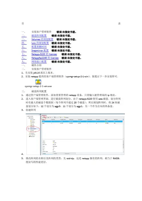
2、进入客户端管理界面,进行磁盘阵列划分,由于netappv3220使用sata磁盘,划分阵列时有最大的磁盘个数限制(每个阵列不超过20个磁盘),所以规划阵列时,将24块磁盘划分如下:12个划分为aggr0,11个划分为aggr1,另一个作为全局的热备盘。
3、创建阵列4、5、修改阵列的名称以及阵列的类型,先raid-dp,这是netapp独有的阵列,相当于RAID6,便读写的性能更好。
6、7、根椐提示进入下一步,按规划选择要做阵列aggr0数量为12个硬盘,并进入下一步配置完阵列,另一个阵列选aggr1需要11个硬盘配置完成阵列,还剩下一个硬盘,netapp 会自动配置作为全局热备盘。
8、四、Volumes的规划配置根椐规划,会划分四个volume,aggr0会划分三个volume,aggr1会划分为一个volume,每个volume都会开启活动volume功能,最大限度的利用volume的容易,每个volume划分的大小为每个阵列的最大容量的95%,另个5%作为netapp的快照功能,这是netapp公司建议的容量分配方式,虽有小许的容量损失,但能发挥netapp最佳的优能。

NetApp存储设备配置说明修改记录目录1编写目的 (1)2专业名词和缩略语 (2)3组网方式和环境介绍 (3)4安装配置方法 (3)4.1N ET A PP硬件安装 (3)4.2设备初始化和系统设定 (4)4.2.1设备初始化 (4)4.2.2系统设定 (4)4.3操作系统安装 (6)4.3.1注册现有系统的cifs服务,将操作系统文件上传至FAS存储系统 (6)4.4应用配置 (8)4.4.1系统参数配置 (8)4.4.2注册需要使用的服务 (10)4.4.3创建一个卷并输出空间 (12)4.4.4创建一个Qtree并实施quota限制 (17)4.4.5配置autosupport (19)4.4.6配置snapshot策略及数据恢复方法 (19)4.4.7磁盘故障的数据恢复方法 (19)4.4.8配置Cluster (19)1 编写目的编写本文档的目的在于详细地说明NetApp FAS存储系统的安装、配置以及常用命令的介绍和可靠性维护、故障检查与恢复的方法,便于开发、测试、用服和工程维护人员安装、使用和维护NetApp FAS存储系统存储系统。
2 专业名词和缩略语3 组网方式和环境介绍NetAppFAS3240AESX ServerSWITCHESX Server图3.1 NetApp FAS存储系统组网结构NetApp FAS存储系统存储设备以NAS存储方式使用,通过万兆交换机与主机相连接。
4 安装配置方法4.1 NetApp硬件安装存储设备硬件的安装主要是各盘柜间线缆的连接、磁盘安装、盘柜上架、上电等,以上操作多由NetApp技术支持工程师完成。
使用存储设备随机携带的“DB-9 to RJ-45”转接线将FAS存储系统的CONSOLE端口和安装了WINDOWS操作系统的主机串口相连,在WINDOWS主机上安装SecureCRT软件,新建一个serial协议的连接,其中port参数根据所连接的是COM1还是COM2来进行选择,其余参数参考图4.1所示,通过串口连接登录到FAS存储系统。
NetApp FAS系列基本操作配置目录App存储系统 (3)2.系统基本操作维护指南 (5)2.1. 存储初始化配置 (5)2.2. 进入管理界面 (7)2.3. 系统基本信息 (8)2.4. 系统LOG信息 (9)2.5. 配置Autosupport (10)2.6. 设置时区、时间和日期 (10)2.7. 杂项设置 (11)2.8. 停机及重新启动 (12)2.9. 管理创建AGGR及卷 (13)2.10. 管理及创建Qtree (15)2.11. 磁盘配额 (16)2.12. SnapShot的配置和管理 (18)2.13. CIFS的相关信息 (20)2.14. CIFS共享 (23)2.15. ISCSI配置 (25)2.16. FC SAN配置 (29)2.17. 网络端口的管理 (32)2.18. 其他网络参数 (33)2.19. 更改root用户密码 (35)2.20. 系统实时状态监控 (35)附录一:磁盘更换步骤 (37)附录二:时间同步服务器的设置 (38)App存储系统NetApp 系统为各种不同平台上的用户提供了对全部企业数据的无缝访问。
NetApp全系列光纤网络存储系统在文件访问方面支持NFS 和CIFS,在块存储访问方面支持FCP 和iSCSI,确保您可以非常方便地将NetApp 存储系统集成到NAS 或SAN 环境中,并且保护原来的信息。
NetApp 的设计为专用访问环境中的应用程序服务器和服务器集群以及多用户环境中的用户提供了经过优化和整合的高性能数据访问方式。
NetApp 存储系统提供了经过实践考验的、超过99.998% 的数据可用性,减少了代价高昂的停机时间(无论是计划内的还是计划外的),最大限度地保障了对关键数据的访问。
它们在一个简单、易用的环境中实现了数据的可管理性、可扩展性、互操作性和可用性,从而降低了您的总拥有成本,加强了竞争优势。
NetApp系列产品具备真正的“统一引擎”功能,使您可以同时支持文件级和块级数据访问—而以前需要有多个系统才能完成这些过程。
NEC Express5800 ServersSystem Configuration GuideImportant NoteIntroductionThis document contains product and configuration information that will enable you to configure your system. The guide will ensure fast and proper configuration of your NEC Express5800 server.March 12, 2018Revision 1.0NEC CorporationContentsSSD LIFESPAN (RACK / TOWER / MODULER SERVER) (3)REVISION HISTORY (5)SSD Lifespan (Rack / Tower / Moduler server)The NAND flash SSDs has limited lifespan, which can be written the limited amount. The warranty period is the stated period of warranty or until the total bytes of written amount (PBW) exceeds the limit value, whichever occurs first.Refer to below table for the lifespan and monitoring tool.EXPRESSBUILDER EXPRESSBUILDER (Test and diagnostics) N8150-722 400GB Hot Plug 2.5-inch SAS SSD 5 years 7.3PBW N8150-766400GB Hot Plug 2.5-inch SAS SSD5 years7.3PBWUniversal RAID Utility,Lifespan monitoring tool for SAS HBA,EXPRESSBUILDER (Test and diagnostics)N8150-748 400GB Hot Plug 2.5-inch SAS SSD 5 years 7.0PBW Smart Storage AdministratorEXPRESSBUILDER (Test and diagnostics)N8150-726 400GB Hot Plug 2.5-inch SATA SSD 5 years 7.3PBW N8150-727 800GB Hot Plug 2.5-inch SATA SSD 5 years 14.6PBW N8150-767 200GB Hot Plug 2.5-inch SATA SSD 5 years 3.0PBW N8150-768 400GB Hot Plug 2.5-inch SATA SSD 5 years 6.1PBW N8150-769 800GB Hot Plug 2.5-inch SATA SSD 5 years 12.3PBW N8150-779 200GB Hot Plug 2.5-inch SATA SSD 5 years 3.0PBW Universal RAID Utility,Lifespan monitoring tool for SAS HBA,EXPRESSBUILDERN8150-780 400GB Hot Plug 2.5-inch SATA SSD 5 years 6.1PBW N8150-781800GB Hot Plug 2.5-inch SATA SSD5 years12.3PBWEXPRESSBUILDER (Test and diagnostics)N8150-733 400GB Hot Plug 2.5-inch SATA SSD 5 years 3.0PBW N8150-734 800GB Hot Plug 2.5-inch SATA SSD 5 years 5.3PBW N8150-735 1.6TB Hot Plug 2.5-inch SATA SSD 5 years 10.7PBW N8150-770 240GB Hot Plug 2.5-inch SATA SSD 5 years 1.3PBW N8150-771 480GB Hot Plug 2.5-inch SATA SSD 5 years 2.6PBW N8150-772 960GB Hot Plug 2.5-inch SATA SSD 5 years 5.2PBW N8150-773 1.92TB Hot Plug 2.5-inch SATA SSD 5 years 10.5PBW N8150-782 200GB Hot Plug 2.5-inch SATA SSD 5 years 1.1PBW Universal RAID Utility,Lifespan monitoring tool for SAS HBA,EXPRESSBUILDER (Test and diagnostics)N8150-783 400GB Hot Plug 2.5-inch SATA SSD 5 years 3.0PBW N8150-784 800GB Hot Plug 2.5-inch SATA SSD 5 years 5.3PBW N8150-785 1.6TB Hot Plug 2.5-inch SATA SSD 5 years 10.7PBW N8150-739 240GB Hot Plug 2.5-inch SATA SSD 5 years 2.1PBW Smart Storage AdministratorN8150-740 480GB Hot Plug 2.5-inch SATA SSD 5 years 3.0PBW N8150-741960GB Hot Plug 2.5-inch SATA SSD5 years6.1PBWN8150-744 480GB Hot Plug 2.5-inch SATA SSD 5 years 0.7PBWN8150-745 960GB Hot Plug 2.5-inch SATA SSD 5 years 1.4PBWN8150-746 1.92TB Hot Plug 2.5-inch SATA SSD 5 years 2.8PBWEXPRESSBUILDER(Test and diagnostics) N8150-754 120GB Non-hot-plug M.2 SATA SSD 5 years 0.06PBW Smart Storage Administrator N8150-778 150GB Non-hot-plug M.2 SATA SSD 5 years 0.08PBWNOTE:●PBW (Peta-Bytes Written): Total amount of written data. 1PB = 1,000TB.●Please check the SSD lifespan periodically by monitoring tools. F or details, refer to User’s Guide.●NEC recommends to re-purchase and replace SSD before lifespan was reached. For details, please contact your salesrepresentative.Revision History。
H3C Neocean EX1500系列网络存储系统安装手册杭州华三通信技术有限公司资料版本:5P104-20100108声明Copyright © 2008-2010 杭州华三通信技术有限公司及其许可者版权所有,保留一切权利。
未经本公司书面许可,任何单位和个人不得擅自摘抄、复制本书内容的部分或全部,并不得以任何形式传播。
H3C、、Aolynk、、H3Care、、TOP G、、IRF、NetPilot、Neocean、NeoVTL、SecPro、SecPoint、SecEngine、SecPath、Comware、Secware、Storware、NQA、VVG、V2G、V n G、PSPT、XGbus、N-Bus、TiGem、InnoVision、HUASAN、华三均为杭州华三通信技术有限公司的商标。
对于本手册中出现的其它公司的商标、产品标识及商品名称,由各自权利人拥有。
由于产品版本升级或其他原因,本手册内容有可能变更。
H3C保留在没有任何通知或者提示的情况下对本手册的内容进行修改的权利。
本手册仅作为使用指导,H3C尽全力在本手册中提供准确的信息,但是H3C并不确保手册内容完全没有错误,本手册中的所有陈述、信息和建议也不构成任何明示或暗示的担保。
技术支持用户支持邮箱:customer_service@技术支持热线电话:800-810-0504(固话拨打)400-810-0504(手机、固话均可拨打)网址:相关资料及其获取方式相关资料手册名称用途《H3C Neocean EX1500系列网络存储管理软件用户手册》描述如何通过NeoStor控制台配置、管理和维护EX1500网络存储系统。
《H3C Neocean DE1116 磁盘柜安装手册》描述DE1116磁盘柜的外观、电源模块、散热系统、指示灯和产品规格,详细指导设备和配置电缆的安装步骤。
资料获取方式您可以通过H3C网站()获取最新的产品资料:H3C网站与产品资料相关的主要栏目介绍如下:z[产品技术]:可以获取产品介绍和技术介绍的文档。

宁畅服务器安装手册为了使用宁畅服务器,您需要按照以下步骤进行安装。
请注意,此手册适用于在Windows操作系统上安装宁畅服务器。
步骤1:下载宁畅服务器安装包首先,您需要从宁畅官方网站上下载宁畅服务器的安装包。
确保您选择与您的操作系统兼容的安装包版本。
步骤2:运行安装程序一旦下载完成,找到安装包文件并双击运行。
您将看到一个安装向导,按照指示进行操作。
步骤3:选择安装目录在安装向导中,您将被要求选择宁畅服务器的安装目录。
您可以选择默认目录,或者选择您自己喜欢的目录。
步骤4:选择组件在安装过程中,您可以选择安装哪些组件。
根据您的需求,您可以选择安装额外的插件或工具。
步骤5:配置服务器设置在安装过程的某个阶段,您将被要求配置宁畅服务器的一些基本设置,例如端口号和管理员密码。
请确保您选择一个强密码,并记住它。
步骤6:完成安装一旦配置完成,安装程序将开始安装宁畅服务器到您选择的目录。
请耐心等待安装过程完成。
步骤7:启动宁畅服务器安装完成后,您可以在“开始”菜单中找到宁畅服务器的快捷方式。
双击它启动服务器。
步骤8:测试服务器连接打开您喜欢的网络浏览器,并输入服务器的IP地址和端口号。
如果一切正常,您将看到宁畅服务器的登录页面。
步骤9:登录并配置服务器使用您在步骤5中设置的管理员密码登录宁畅服务器。
一旦登录,您可以根据需要配置和自定义服务器设置。
现在,您已经成功安装和配置了宁畅服务器。
您可以开始使用它来托管您的网站或应用程序,并享受它提供的诸多功能和性能优势。
请确保定期更新和维护服务器,以确保其安全性和稳定性。
MacroSAN MS2500G2系列存储设备安装手册文档版本:V1.45杭州宏杉科技股份有限公司400-650-5527声明版权所有©2021杭州宏杉科技股份有限公司。
保留所有权利。
未经杭州宏杉科技股份有限公司书面许可,任何单位和个人不得擅自摘抄本手册的内容,且不得以任何形式传播本手册。
本手册仅作为操作参考,由于软件版本升级或其他原因,本手册的内容可能滞后于最新的软件版本或设备配置,杭州宏杉科技股份有限公司保留在没有任何通知或提示的情况下对本手册的内容进行修改的权利。
商标信息MacroSAN、ODSP、ODSP_MSC、ODSP_JMC、ODSP Scope、宏杉均为杭州宏杉科技股份有限公司的商标。
对于本手册中出现的其他公司的商标、产品标识及商品名称,由各自权利人拥有。
目录MacroSAN MS2500G2系列存储设备 ..................................................................................................... 1-1安装手册 .................................................................................................................................................. 1-1声明.......................................................................................................................................................... 1-2商标信息 .................................................................................................................................................. 1-2目录.......................................................................................................................................................... 1-3图目录...................................................................................................................................................... 1-8表目录.................................................................................................................................................... 1-12 1前言..................................................................................................................................................... 1-151.1 读者对象.................................................................................................................................... 1-151.2 适用范围.................................................................................................................................... 1-151.3 文档结构.................................................................................................................................... 1-151.4 文档约定.................................................................................................................................... 1-161.4.1 手册描述约定................................................................................................................... 1-161.4.2 其他约定.......................................................................................................................... 1-171.5 术语........................................................................................................................................... 1-171.5.1 DSU ................................................................................................................................ 1-171.5.2 EMC ................................................................................................................................ 1-171.5.3 EP ................................................................................................................................... 1-171.5.4 FC ................................................................................................................................... 1-171.5.5 GE ................................................................................................................................... 1-171.5.6 GUI ................................................................................................................................. 1-171.5.7 iSCSI ............................................................................................................................... 1-171.5.8 ODSP .............................................................................................................................. 1-171.5.9 ODSP Scope ................................................................................................................... 1-171.5.10 ODSP Scope+ ............................................................................................................... 1-181.5.11 SAN............................................................................................................................... 1-181.5.12 SAS ............................................................................................................................... 1-181.5.13 SATA ............................................................................................................................. 1-181.5.14 SP ................................................................................................................................. 1-181.5.15 SPU............................................................................................................................... 1-181.5.16 SSD............................................................................................................................... 1-181.6 资料获取方式............................................................................................................................. 1-181.7 资料意见或建议反馈方式............................................................................................................ 1-18 2设备使用注意事项............................................................................................................................... 2-192.1 用电安全注意事项...................................................................................................................... 2-192.2.2 无防静电腕带时紧急操作方法 .......................................................................................... 2-202.3 激光安全注意事项...................................................................................................................... 2-202.4 电池安全注意事项...................................................................................................................... 2-202.5 EMC注意事项 ........................................................................................................................... 2-212.6 磁盘使用注意事项...................................................................................................................... 2-212.7 操作安全注意事项...................................................................................................................... 2-22 3产品介绍 ............................................................................................................................................. 3-223.1 产品概述.................................................................................................................................... 3-223.2 产品规格.................................................................................................................................... 3-233.2.1 SPU规格......................................................................................................................... 3-233.2.2 DSU规格......................................................................................................................... 3-263.2.3 磁盘模块规格................................................................................................................... 3-273.3 产品外观.................................................................................................................................... 3-283.3.1 产品高度说明................................................................................................................... 3-283.3.2 2U SPU外观 ................................................................................................................... 3-283.3.3 4U SPU外观 ................................................................................................................... 3-383.3.4 2U DSU外观 ................................................................................................................... 3-443.3.5 3U DSU外观 ................................................................................................................... 3-493.3.6 4U DSU外观 ................................................................................................................... 3-533.3.7 电源模块外观................................................................................................................... 3-563.3.8 磁盘模块外观................................................................................................................... 3-573.4 产品指示灯 ................................................................................................................................ 3-603.4.1 SP指示灯........................................................................................................................ 3-603.4.2 EP指示灯........................................................................................................................ 3-613.4.3 风扇模块和电池模块指示灯.............................................................................................. 3-613.4.4 电源模块指示灯 ............................................................................................................... 3-633.4.5 磁盘模块指示灯 ............................................................................................................... 3-633.4.6 IO插卡模块指示灯........................................................................................................... 3-63 4安装设备 ............................................................................................................................................. 4-654.1 安装规划.................................................................................................................................... 4-654.2 安装流程.................................................................................................................................... 4-664.3 安装前准备 ................................................................................................................................ 4-674.3.1 准备安装场所................................................................................................................... 4-674.3.2 准备机柜.......................................................................................................................... 4-704.3.3 准备安装工具................................................................................................................... 4-714.4 安装前检查 ................................................................................................................................ 4-714.4.1 检查环境.......................................................................................................................... 4-714.4.3 检查线缆.......................................................................................................................... 4-744.5 安装机柜.................................................................................................................................... 4-754.5.1 安装机柜.......................................................................................................................... 4-754.5.2 安装机柜后检查 ............................................................................................................... 4-754.6 安装托架式滑道 ......................................................................................................................... 4-754.6.1 托架式滑道介绍 ............................................................................................................... 4-754.6.2 确定滑道位置................................................................................................................... 4-764.6.3 安装滑道.......................................................................................................................... 4-774.6.4 安装滑道后检查 ............................................................................................................... 4-794.7 安装SPU ................................................................................................................................... 4-794.7.1 安装SPU流程................................................................................................................. 4-794.7.2 安装SPU到机柜中.......................................................................................................... 4-804.7.3 安装SPU电池模块和拆卸电池模块假面板(可选) ......................................................... 4-814.7.4 安装SPU磁盘模块和磁盘假面板(可选) ....................................................................... 4-834.7.5 安装SPU后检查 ............................................................................................................. 4-844.7.6 安装SPU面板(可选)................................................................................................... 4-854.8 安装DSU ................................................................................................................................... 4-854.8.1 安装DSU流程................................................................................................................. 4-854.8.2 安装DSU到机柜中.......................................................................................................... 4-864.8.3 安装DSU磁盘模块和磁盘假面板(可选) ....................................................................... 4-864.8.4 安装DSU后检查 ............................................................................................................. 4-874.9 安装线缆.................................................................................................................................... 4-884.9.1 布线注意事项................................................................................................................... 4-884.9.2 安装线缆流程................................................................................................................... 4-904.9.3 安装接地线 ...................................................................................................................... 4-914.9.4 安装电源线 ...................................................................................................................... 4-924.9.5 安装SAS线缆 ................................................................................................................. 4-954.9.6 安装SP业务接口线缆.................................................................................................... 4-1024.9.7 安装SP管理网口线缆.................................................................................................... 4-1054.9.8 安装客户端服务器线缆................................................................................................... 4-1054.9.9 安装线缆后检查 ............................................................................................................. 4-106 5启动与配置设备................................................................................................................................. 5-1065.1 设备上电前检查 ....................................................................................................................... 5-1065.2 设备上电及启动 ....................................................................................................................... 5-1075.2.1 DSU上电及启动 ............................................................................................................ 5-1075.2.2 DSU启动后检查 ............................................................................................................ 5-1075.2.3 SPU上电及启动 ............................................................................................................ 5-1085.3 设备配置.................................................................................................................................. 5-1095.3.1 设备默认配置................................................................................................................. 5-1095.3.2 设备配置准备................................................................................................................. 5-1095.3.3 设备配置........................................................................................................................ 5-1105.4 设备关机及下电 ....................................................................................................................... 5-112 6安装与拆卸设备组件 ......................................................................................................................... 6-1126.1 安装/拆卸SPU面板 ................................................................................................................. 6-1136.1.1 SPU面板介绍................................................................................................................ 6-1136.1.2 安装SPU面板............................................................................................................... 6-1136.1.3 拆卸SPU面板............................................................................................................... 6-1136.2 安装/拆卸SP ........................................................................................................................... 6-1146.2.1 安装/拆卸2U SPU的SP ................................................................................................ 6-1146.2.2 安装/拆卸4U SPU的SP ................................................................................................ 6-1156.3 安装/拆卸EP ........................................................................................................................... 6-1176.3.1 安装/拆卸2U DSU的EP ............................................................................................... 6-1176.3.2 安装/拆卸3U DSU的EP ............................................................................................... 6-1196.3.3 安装/拆卸4U DSU的EP ............................................................................................... 6-1206.4 安装/拆卸SPU风扇模块和电池模块......................................................................................... 6-1216.4.1 安装/拆卸2U SPU风扇模块(无电池模块) .................................................................. 6-1216.4.2 安装/拆卸2U SPU风扇模块(含电池模块) .................................................................. 6-1236.4.3 安装/拆卸4U SPU风扇模块........................................................................................... 6-1246.4.4 安装/拆卸4U SPU电池模块........................................................................................... 6-1256.5 安装/拆卸DSU风扇模块.......................................................................................................... 6-1276.5.1 安装/拆卸2U DSU风扇模块........................................................................................... 6-1276.5.2 安装/拆卸3U DSU风扇模块........................................................................................... 6-1296.5.3 安装/拆卸4U DSU风扇模块........................................................................................... 6-1306.6 安装/拆卸电源模块................................................................................................................... 6-1316.6.1 电源模块介绍................................................................................................................. 6-1316.6.2 安装电源模块................................................................................................................. 6-1336.6.3 拆卸电源模块................................................................................................................. 6-1336.7 安装/拆卸IO插卡模块.............................................................................................................. 6-1336.7.1 IO插卡模块介绍 ............................................................................................................ 6-1346.7.2 安装IO插卡模块 ........................................................................................................... 6-1346.7.3 拆卸IO插卡模块 ........................................................................................................... 6-1356.8 安装/拆卸磁盘模块................................................................................................................... 6-1356.8.1 磁盘模块介绍................................................................................................................. 6-1356.8.2 安装/拆卸2.5英寸磁盘模块A ........................................................................................ 6-1366.8.3 安装/拆卸2.5英寸磁盘模块B ........................................................................................ 6-1376.8.4 安装/拆卸3.5英寸磁盘模块A ........................................................................................ 6-1396.8.5 安装/拆卸3.5英寸磁盘模块B ........................................................................................ 6-1406.8.6 安装磁盘假面板 ............................................................................................................. 6-142 7常见故障处理 .................................................................................................................................... 7-1437.1 SP故障处理 ............................................................................................................................ 7-1437.1.1 故障现象1:SP的告警指示灯闪烁或常亮...................................................................... 7-1437.1.2 故障现象2:SP的运行指示灯常亮或常灭...................................................................... 7-1447.1.3 故障现象3:SP启动过程中,LED数码管无法显示信息 ................................................ 7-1447.1.4 故障现象4:SP启动过程中,LED数码管停留在88 ...................................................... 7-1457.1.5 故障现象5:SP启动过程中,LED数码管长时间停留在某个固定值 ............................... 7-1457.2 EP故障处理 ............................................................................................................................ 7-1457.2.1 故障现象1:告警指示灯闪烁或常亮............................................................................... 7-1457.2.2 故障现象2:运行指示灯常亮或常灭............................................................................... 7-1467.3 风扇模块故障处理.................................................................................................................... 7-1467.4 电池模块故障处理.................................................................................................................... 7-1477.5 电源模块故障处理.................................................................................................................... 7-1477.6 磁盘模块故障处理.................................................................................................................... 7-1487.7 其他故障处理........................................................................................................................... 7-148 8附录A.拇指螺钉的安装方法.............................................................................................................. 8-148 9附录B.中国有害物质声明 ................................................................................................................. 9-151 10附录C. V1.2.40T04之前的版本登录存储设备管理界面的步骤.................................................... 10-152图目录图3-1 2U SPU前正视图(一)............................................................................................................. 3-29图3-2 2U SPU前正视图(二)............................................................................................................. 3-29图3-3 MS2500G2-12S SPU后正视图.................................................................................................. 3-30图3-4 2U SPU的SP正视图(一)...................................................................................................... 3-31图3-5 2U SPU的SP正视图(二)...................................................................................................... 3-33图3-6 2U SPU的SP正视图(三)...................................................................................................... 3-35图3-7 2U SPU风扇模块(无电池模块)正视图................................................................................... 3-37图3-8 2U SPU风扇模块(含电池模块)正视图................................................................................... 3-37图3-9 4U SPU前正视图(带面板) ..................................................................................................... 3-38图3-10 4U SPU前正视图(不带面板)................................................................................................ 3-38图3-11 4U SPU后正视图 ..................................................................................................................... 3-39图3-12 4U SPU的SP正视图............................................................................................................... 3-41图3-13 4U SPU风扇模块正视图........................................................................................................... 3-43图3-14 4U SPU电池模块正视图........................................................................................................... 3-43图3-15 DSU1625前正视图................................................................................................................... 3-44图3-16 DSU2625前正视图................................................................................................................... 3-44图3-17 DSU1625后正视图................................................................................................................... 3-45图3-18 DSU2625后正视图................................................................................................................... 3-45图3-19 DSU1625 EP正视图................................................................................................................. 3-46图3-20 DSU2625的EP正视图 ............................................................................................................ 3-47图3-21 DSU1625风扇模块正视图........................................................................................................ 3-48图3-22 DSU2625风扇模块正视图........................................................................................................ 3-49图3-23 DSU1616前正视图................................................................................................................... 3-50图3-24 DSU1616后正视图................................................................................................................... 3-50图3-25 DSU1616 EP正视图................................................................................................................. 3-51图3-26 DSU1616风扇模块正视图........................................................................................................ 3-52图3-27 DSU2624前正视图................................................................................................................... 3-53图3-28 DSU2624后正视图................................................................................................................... 3-54图3-29 DSU2624 EP正视图................................................................................................................. 3-55图3-30 DSU2624风扇模块正视图........................................................................................................ 3-56图3-31 DSU2624电源模块正视图........................................................................................................ 3-56图3-32 其他电源模块正视图 ................................................................................................................. 3-57图3-34 2.5英寸磁盘模块B前面板 ....................................................................................................... 3-58图3-35 3.5英寸磁盘模块A外观........................................................................................................... 3-59图3-36 3.5英寸磁盘模块B外观........................................................................................................... 3-59图3-37 3.5英寸磁盘模块前面板 ........................................................................................................... 3-59图4-1 存储设备的安装规划示意图 ........................................................................................................ 4-66图4-2 存储设备的安装流程示意图 ........................................................................................................ 4-67图4-3 设备防拆封条示意图 ................................................................................................................... 4-74图4-4 带拇指螺钉托架式滑道(左侧滑道)示意图............................................................................... 4-76图4-5 带定位销托架式滑道(左侧滑道)示意图 .................................................................................. 4-76图4-6 安装带拇指螺钉的托架式左侧滑道示意图 .................................................................................. 4-77图4-7 安装拇指螺钉示意图 ................................................................................................................... 4-78图4-8 检查滑道示意图........................................................................................................................... 4-78图4-9 安装带定位销的托架式左侧滑道示意图...................................................................................... 4-79图4-10 SPU安装流程示意图 ................................................................................................................ 4-80图4-11 安装SPU示意图....................................................................................................................... 4-81图4-12 安装2U SPU风扇模块(含电池模块)示意图......................................................................... 4-82图4-13 安装4U SPU电池模块示意图 .................................................................................................. 4-83图4-14 安装SPU面板示意图 ............................................................................................................... 4-85图4-15 DSU安装流程示意图................................................................................................................ 4-85图4-16 安装DSU示意图 ...................................................................................................................... 4-86图4-17 固定线缆端子示意图 ................................................................................................................. 4-88图4-18 线缆捆扎示意图(一).............................................................................................................. 4-89图4-19 线缆捆扎示意图(二).............................................................................................................. 4-90图4-20 线缆捆扎示意图(三).............................................................................................................. 4-90图4-21 线缆安装流程示意图 ................................................................................................................. 4-91图4-22 接地线示意图 ............................................................................................................................ 4-91图4-23 松开设备接地端子的螺钉示意图............................................................................................... 4-92图4-24 安装接地线示意图..................................................................................................................... 4-92图4-25 电源线示意图 ............................................................................................................................ 4-93图4-26 安装电源线示意图(二).......................................................................................................... 4-93图4-27 电源线捆扎示意图..................................................................................................................... 4-94图4-28 安装电源线示意图(一).......................................................................................................... 4-94图4-29 A类SAS线缆示意图................................................................................................................ 4-95图4-30 B类SAS线缆示意图................................................................................................................ 4-96。
NetApp存储设备配置说明修改记录目录1编写目的 (1)2专业名词和缩略语 (2)3组网方式和环境介绍 (3)4安装配置方法 (3)4.1N ET A PP硬件安装 (3)4.2设备初始化和系统设定 (4)4.2.1设备初始化 (4)4.2.2系统设定 (4)4.3操作系统安装 (6)4.3.1注册现有系统的cifs服务,将操作系统文件上传至FAS存储系统 (6)4.4应用配置 (8)4.4.1系统参数配置 (8)4.4.2注册需要使用的服务 (10)4.4.3创建一个卷并输出空间 (12)4.4.4创建一个Qtree并实施quota限制 (17)4.4.5配置autosupport (19)4.4.6配置snapshot策略及数据恢复方法 (19)4.4.7磁盘故障的数据恢复方法 (19)4.4.8配置Cluster (19)1 编写目的编写本文档的目的在于详细地说明NetApp FAS存储系统的安装、配置以及常用命令的介绍和可靠性维护、故障检查与恢复的方法,便于开发、测试、用服和工程维护人员安装、使用和维护NetApp FAS存储系统存储系统。
2 专业名词和缩略语3 组网方式和环境介绍NetAppFAS3240AESX ServerSWITCHESX Server图3.1 NetApp FAS存储系统组网结构NetApp FAS存储系统存储设备以NAS存储方式使用,通过万兆交换机与主机相连接。
4 安装配置方法4.1 NetApp硬件安装存储设备硬件的安装主要是各盘柜间线缆的连接、磁盘安装、盘柜上架、上电等,以上操作多由NetApp技术支持工程师完成。
使用存储设备随机携带的“DB-9 to RJ-45”转接线将FAS存储系统的CONSOLE端口和安装了WINDOWS操作系统的主机串口相连,在WINDOWS主机上安装SecureCRT软件,新建一个serial协议的连接,其中port参数根据所连接的是COM1还是COM2来进行选择,其余参数参考图4.1所示,通过串口连接登录到FAS存储系统。
亿玖Xeon Scalable存储服务器24/36盘位可选亿玖EN系列存储服务器采用了Intel C620系列高性能芯片组,支持两颗第二代英特尔® 至强® 可扩展系列处理器,该机型最多支持内存容量3TB,支持2U12盘/4U24盘/4U36盘热插拔3.5/2.5寸硬盘,12GB高速扩展背板,拥有6个PCI扩展插槽,可灵活扩展全高全长的PCI-E设备。
提供先进的管理功能和存储技术。
亿玖EN系列存储服务器使用的高安全性的冗余(1+1),在紧急时刻保证数据的安全,具有可靠的可扩充性和高可用性。
存储适用于分布式存储,大数据存储,视频存储。
智能,大规模虚拟化和大型节点技术计算。
4U的空间能支持36个硬盘位可支持更多的数据存储,帮助大型的视频剪辑公司使用最小的空间来获得更大的存储空间。
通过提高安全性,消除 I/O 瓶颈,优化密度和性能,提供可靠的虚拟资源,解决数据爆炸性增长带来的存储挑战,为私有云、公共云与混合云提供最为出色和可靠的解决方案。
支持2 颗Intel® Xeon® Scalable系列处理器,可提供强大的计算能力,帮助用户应对较重的计算压力。
支持英特尔® 增强型英特尔SpeedStep技术,英特尔®高级矢量扩展指令集(英特尔® AVX2)。
8个内存DIMM槽,最大支持2TB RECC 2933MHz DDR4。
板载10个SATA3(6Gbps)接口,支持RAID 0,1,5,10。
2个PCI-E3.0X16,3个PCI-E 3.0X8扩展槽1个PCI-E 3.0 x4 (in x8 slot),可提供更灵活的扩展性能。
板载2个千兆数据网口,具有负载均衡和冗余的特性,可有效减少网络延迟。
集成BMC模块,提供独立的RJ45远程管理端口,支持IPMI2.0,支持远程管理、iKVM。
支持8个3.5寸/2.5寸SATA热插拔硬盘位,可满足各类应用对存储空间需求。
NETAPP存储系统安装、配置和维护手册文档信息本安装和维护手册为 XXX 定制,为NetApp标准文档之补充。
目录1作业规划步骤 (1)2配置步骤 (3)2.1设置磁盘归属,创建ROOT卷 (3)2.2检查并更新各部件的firmware系统版本 (15)2.3检查并更新存储操作系统版本 (19)2.4输入软件许可 (23)2.5执行SETUP进行初始化设置 (23)2.6调整ROOT卷的大小 (29)2.7配置VLAN (29)2.8修改HOSTS文件 (31)2.9修改/etc/rc文件 (32)2.10配置AutoSupport服务 (33)2.11配置SSH (34)2.12配置SNMP (35)2.13配置NTP (36)2.14配置MTA (37)2.15配置IPspace (37)2.16配置MultiStore (37)2.17配置CIFS (41)2.18配置ISCSI (44)2.19配置FCP (45)2.20配置NFS (46)2.21配置重复数据删除 (47)2.22配置Snaprestore (48)2.23容灾实现Snapmirror (52)3日常维护 (55)3.1正常开关机 (55)3.2维护手段 (55)3.2.1Filerview 图形管理接口 (55)3.2.2命令行(CLI) (57)3.3空间管理:Aggr, Volume和lun的介绍 (57)3.4常用命令基本应用 (58)3.5日常系统检查 (58)3.5.1目测 (58)3.5.2例行系统检查 (58)3.6autosupport功能简介和配置 (59)4故障处理流程 (61)Page II4.1支持方式 (61)4.1.1NetApp on the web (NOW) site和服务 (61)4.1.2GSC( Global Support Center 全球支持中心) (61)4.2案例开立流程 (62)4.3损坏部件更换流程 (62)Page III1 作业规划步骤Page 22 配置步骤配置参数表2.1 设置磁盘归属,创建ROOT卷Page 3Page 4Page 5Page 6Page 7Page 8Page 9Page 10Page 11Page 12Page 13Page 142.2 检查并更新各部件的firmware系统版本Page 15Page 16Page 17Page 182.3 检查并更新存储操作系统版本Page 19Page 20Page 21Page 222.4 输入软件许可使用license add XXXXXXX命令添加许可,全部输入后,使用license命令进行检查。
存储系统安装调试手册(N V R) ——成都佳发安泰科技有限公司——目录1、准备工作、所需软件所需软件:(1)JF-W(2)mysql-connector-odbc(3)(4)MicroDog:软件狗驱动( 5 )WinPcap_4_1_2(6)vnc-E4_2_9-x86_win32_CHS远程控制软件(7)佳发专用播放器。
、所需硬件佳发存储软件狗一个。
、前期准备需将JF-WWinPcap_4_1_2这3个文件放到电脑c盘根目录下操作运行,其他文件放在d盘,将佳发存储软件狗插到服务器USB口上。
2、NVR的安装、管理中心的安装、开始安装管理中心,运行JF-W目录下的,出现该界面:该界面表明管理中心正在安装,期间光标不停闪动,直到该界面自动消失时,说明管理中心已经安装完毕。
下一步,在运行中输入,进入服务界面:在该界面中,启动Apache Tomcat 6服务选择JF-NVR出现管理中心界面:到此NVR管理中心安装完毕。
、WinPcap_4_1_2的安装管理中心安装完毕后,接着安装WinPcap_4_1_2点击next---next—I Agree---Install---finish 即可、ODBC安装WinPcap_4_1_2安装完毕后,接着安装ODBC驱动程序选择next选择complete---next----insetll即可安装完毕后,在控制面板-管理工具中找到数据源(ODBC)并打开,在系统DSN中进行添加一个新的驱动连接:选择MySQL ODBC Drvier,出现配置界面:实际配置参数按照示意图中填写即可注意:Data Source Name、user、password 必须和JF-NVR(mdp)中中的一样:ODBC安装及配置到此结束、安装软件狗把并口驱动的对号去掉点击安装即可、VNC的安装打开vnc文件夹点击应用程序及文本文件,如下图:下一步---同意—下一步---下一步—下一步此处需要全选,下一步---安装此处点击配置。
USAAddress: 2570 N. First Street, Suite 200, San Jose, CA 95131TEL: +1 888-598-9901JapanAddress: 〒810-0012 福岡県福岡市中央区白金1丁目21−162階 TEL: +81 050-6865-7085ChinaAddress: ShouchuanCenter, No.6 Changcheng South Road,Chengyang District, Qingdao, China, 266109 TEL: +86 532 87963900 Email: *******************Web: Installation and Operation Manual NEP Gateway BDG256/BDG-256P3N136CONCENTSCOMPANY PROFILE1. INTRODUCTION1.1Prefix1.2 How to Use This ManualSAFETY INSTRUCTION2.FCC COMPLIANCE3. INSTALLTION4. USER INTERFACE4.1 Main Interface4.2Interface Overview4.3 Energy functions4.4 Setting4.5 Backup/Clear Data4.6 Status Bar5. WEB INTERFACE6. SPECIFICATION7. WARRY AND PRODUCTION INFORMATION WARRY CARD 0102 02 02 020203 05 050506070809101112 14COMPANY PROFILENorthern Electric Power Inc. (NEP) was founded in the United States and has manufacturing and R&D facilities in China. The mission of the company is to develop cutting-edge clean energy technologies and provide state-of-the-art solar inverter products to its customers.NEP has a complete product line of grid-tied solar inverters, including 250W~800W micro inverters, Rapid shutdown. Field deployment results demonstrated high system efficiency and reliability of NEP solar inverters.NEP is committed to develop Clean, Reliable, Affordable and Efficient(CARE) products forworldwide customers.1.INTRODUCTION1.1 PrefixDear customer, thank you for choosing the BDG-256/BDG-256P3communication gateway for BDM micro inverters. We hope you will find our products meet your need for renewable energy. Meantime,we appreciate your feedback regarding our products.1.2 How to Use This ManualThis manual provides detailed product information and installation instructions for theBDG-256/BDG-256P3 micro solar inverter. Please read through this manual before installation and operation.WARNING: This indicates a situation where failure to follow instructions may be a safety hazard or cause equipment malfunction. Use extreme caution and follow instructions carefully.SAFETY INSTRUCTIONWARNING:PLEASE READ THIS MANUAL BEFORE INSTALLATION. ANY DAMAGE TO THE PRODUCT DUE TO NOT FOLLOWING THIS MANUAL IS NOT COVERED BY THE WARRANTEE.BESIDES THE CABLE CONNECTORS, NOTHING INSIDE THE GATEWAY SHOULD BE MODIFIED. ALL INSTALLATION SHOULD FOLLOW THE LOCAL ELECTRIC CODES.BDG-256/BDG-256P3 DOES NOT INCLUDE COMPONENTS THAT CAN BE SERVED BY CUSTOMERS.PLEASE CONTACT AUTHORIZED SERVICE AGENTS FOR ANY SERVICE WORK.2.FCC COMPLIANCEThis equipment has been tested and found to comply with the limits for a Class B digital device, pursuant to part 15 of the FCC Rules. These limits are designed to provide reasonable protection against harmful interference in a residential installation. This equipment generates uses and can radiate radio frequency energy and, if not installed and used in accordance with the instructions, may cause harmful interference to radio communications. However, there is no guarantee that interference will not occur in a particular installation. If this equipment does cause harmful interference to radio or television reception, which can be determined by turning the equipment off and on, the user is encouraged to try to correct the interference by one or more of the following measures:●Reorient or relocate the receiving antenna.●Increase the separation between the equipment and the receiver.●Connect the equipment into an outlet on a circuit different from that to which the receiver is connected.●Consult the dealer or an experienced radio/TV technician for help.Changes or modifications not expressly approved by the party responsible for compliance may void the user’s authority to operate the equipment.(Australia) (Europe) Other Parts and ToolsFigure 1 BDG-256 Front View Figure 2 BDG-256P3 Side View Outdoor installationWhen installed outdoor, BDG-256 must be inside a weather proof outdoor enclosure. For U.S. and Japan installations, L1 and L2 wires shall be connected to the power terminal inside the weather proof outdoor enclosure. For installations in Europe, L and N wires shall be connected to the power terminal inside the weather proof outdoor enclosure.Figure 3 BDG-256 inside a weather proof outdoor enclosureIndoor installationBDG-256 and BDG-256P3 can be installed indoor by being directly mounted on a wall. The power plug should be plugged in 240Vac (for U.S and Japan) or 230Vac (for Europe and other countries) power outlet. The power outlet shall have no GFDI protection.Figure 4 Back View Figure 5 Front ViewFigure 6 240Vac outlet (US and Japan)Figure 7 230Vac outlet (Europe)4.3 Energy FunctionsA menu bar locates on the top of the screen. Different screen pages on energy and power can be called by pressing on these menu buttons. 4.3.1 Today’s EnergyPressing this button will display the power-time curve screen (see Figure 10). The x-axis represents the time (4:00-20:00), and the y-axis represents NEP micro inverters (BDM-250) output power (kW). The total output energy (kWh) is displayed on the upper left corner. The real-time output power (kW) and today's total energy generated (kWh) are displayed on the upper right corner. Part of the curve can be magnified by drawing a box on the curve using finger or touch pen. Pressing the Today's Energy button again cancels the enlarged display and restores the original display. Figure 10 Today’s PowerFigure 11 Drawing a box on Today’s Power4.3.2 Last 7 Days’ EnergyPressing this button will bring up a bar chart showing power generation over the past 7 days (see Figure 12)..The x-axis represents the date and the last one corresponds to today. The y-axis represents the amount of energy generated (kWh) on the day.Figure 12 Last 7 Days’ Energy4. USER INTERFACE4.1 Main InterfaceBDG-256/BDG-256P3 takes approximately 1-2 minutes to start up after power has beenturned on. After start-up, the system will enter the main interface shown in Fig. 8 (all three numbers will read “0” at start-up for the first time).Figure8 BDG-256/BDG-256P3 Main Display Figure 8 shows the BDG-256/BDG-256P3 main interface. The main interface is arranged inthree horizontal rows, which consist of the tool bar at the very top, the display area in themiddle, and the status bar at the lower part of the screen. The tool bar contains 7 buttons: Save/Clear (backup/restore factory defaults), Summary Display (summary display interface), Today's Energy (current day power generation), 7-Day's Energy (power generation over the past 7 days), Monthly Energy (power generation over each month), Yearly Energy (power generation over each year), and Settings. These buttons are used to display their respectivecontent inthe middle display area. The display area shows the power-time curve for the current day as well as a power generation bar chart. The status bar shows the device status, IP address, and current date.4.2 Interface Overview If the main interface is idle for 2-3 sec., it will switch to a numeric summary interface, which is described below: The screen is divided into three parts. The upper part shows Today's Energy (current day power generation), the lower right corner shows Lifetime (total power generation since device started recording), and the lower left corner shows CO2 reduction(reduction in carbon dioxide emissions). Touching any part of the screen will bring up the main interface. Figure 9BDG-256/BDG-256P3 System Summary Display4.4.2 Date & Time SettingTheDate & Time settings tab (Figure 16) is used to set the date, time, andtime zone. BDG-256supports all five time zone of North America. For other parts of the world, the time zone “World”may be chosen.Figure 16Date & Time Setting4.4.3 Communication Address SettingThe communications address settings tab (Figure 1 17) is used to set the power line communication address of the micro-inverters linked to the device. One BDG-256 gateway can monitor up to 255 micro inverters.Inverter-0 on the address list corresponds to the total output of all inverters connected to the gatewayAddress settings can be input using either the small input panel on the touch-screen or an external USB keyboard. The communication address of a micro inverter consists of the 8 hex characters (0~F) on the BDM micro inverter bar code before the last letter for country. Another way to input the micro inverter communication address is through an internal web portal (see Section 5).Figure 17 Communication Address Setting4.5 Backup/Clear DataWhen a USB flash disk is inserted, press the Save/Clear button to call up the following dialog box (see Figure 18).4.3.3 Monthly EnergyPressing this button will bring up a bar chart showing power generation over each month for the last 12 months (see Figure 13). This display is similar to the Last 7 Days' Energy display. The x-axis represents months and the current month is on the last. The y-axis represents the amount of energy generated (kWh) in the month. Figure 13 Monthly Energy4.3.4 Lifetime EnergyPressing this button brings up a bar chart showing power generation over each year for the past 20 years (see Figure 14). This display is also similar to the Last 7 Days' Energy display.The x-axis represents the years and the current year locates on the last. The y-axis representsthe amount of energy generated (kWh) in the year.Figure 14 Yearly Energy4.4 SettingPressing the Setting button will bring up the settings dialogs.4.4.1 IP Setting BDG-256's IP address may be manually set in the Ethernet settings tab (Figure 15). Theymay also be obtained through DHCP (requires a system restart after setting). If the IP address must be changed, double click on the address box to bring up a small keypad on the screen.Figure 15 IP SettingMicro inverter addressFigure 18 Backup/Clear Data5.WEB INTERFACEThe BDG-256/BDG-256P3 information can be accessed through two web pages. The first one is a web server inside the BDG-256/BDG-256P3 gateway. The second one is a web server provided by NEP , which access requires internet service.MICROVIEWER monitoring w/ built-inBDG-256/BDG-256P3The local web portal built inside BDG-256/BDG-256P3 can be accessed through home network without internet service. If there is internet service, however, remote monitoring can be accessed through NEPVIEWER from anywhere at anytimeTo access the web portal inside BDG-256/BDG-256P3, user only needs to type in the IP address ofBDG-256/BDG-256P3 on a web browser. (Please see Section 4.4.1 for configuring the IP address of BDG-256/BDG-256P3). The administration page for inverter address can be accessed by http://GATEWAY-IP/module (for example http://10.208.100.202/module )Figure 19 MICROVIEWER monitoringFigure 20 Inputting inverter s/n through a webpageThis Limited Warranty is provided by Northern Electric & Power Co. Ltd (NEP) and covers defectsin workmanship and materials in your BDG-256/BDG-256P3 communication gateway. This Warranty Period lasts for 1 year from the date of purchase at the point of sale to you, the original end user customer, unless otherwise agreed in writing. You will be required to demonstrate proof of purchase to make warranty claims.This Limited Warranty is transferable to subsequent owners but only for the unexpired portionof the Warranty Period. Subsequent owners also require original proof of purchase as describedin "What proof of purchase is required?"What will NEP do?During the Warranty Period, NEP will, at its option, repair the product (if economically feasible) or replace the defective product free of charge, provided that you notify NEP of the product defect within the Warranty Period, and provided that NEP through inspection establishes the existence of such a defect and that it is covered by this Limited Warranty.NEP will, at its option, use new and/or reconditioned parts in performing warranty repair and building replacement products. NEP reserves the right to use parts or products of original or improved design in the repair or replacement. NEP repairs or replaces a product, its warranty continues for the remaining portion of the original Warranty Period or 90 days from the date of the return shipment to the customer, whichever is greater. All replaced products and all parts removed from repaired products become the property of NEP.How do you get service?If your product requires troubleshooting or warranty service, contact your merchant. If you are unable to contact your merchant, or the merchant is unable to provide service, contact NEP directly at:Northern Electric Power Co. LtdAddress:2570 N. First Street, Suite 200, San Jose, CA 95131Phone:888-598-9901What does this warranty not cover?Claims are limited to repair and replacement or if in NEP's discretion that is not possible, reimbursement up to the purchase price paid for the product. NEP will be liable to you only for direct damages suffered by you and only up to a maximum amount equal to the purchase priceof the product.This Limited Warranty does not warrant uninterrupted or error-free operation of the product or cover normal wear and tear of the product or costs related to the removal, installation, or troubleshooting of the customer's electrical systems. This warranty does not apply to and NEP will not be responsible for any defect in or damage to:1) the product if it has been misused, neglected, improperly installed, physically damaged or altered, either internally or externally, or damaged from improper use or use in an unsuitableenvironment;2)the product if it has been subjected to fire, water, generalized corrosion, biological infestations, or input voltage that creates operating conditions beyond the maximum or minimum limits listed in the NEP product specifications including high input voltage from generators and lightning strikes;3) the product if repairs have been done to it other than by NEP or its authorized service centers (hereafter "ASCs");4) the product if it is used as a component part of a product expressly warranted by another manufacturer;5) the product if its original identification (trade-mark, serial number) markings have been defaced, altered, or removed;6) the product if it is located outside of the country where it was purchased;7) any consequential losses that are attributable to the product losing power whether by product malfunction, installation error or misuse.Disclaimer ProductTHIS LIMITED WARRANTY IS THE SOLE AND EXCLUSIVE WARRANTY PROVIDED BY NEP IN CONNECTION WITH YOUR NEP PRODUCT AND IS, WHERE PERMITTED BY LAW, IN LIEU OF ALL OTHER WARRANTIES, CONDITIONS, GUARANTEES, REPRESENTATIONS, OBLIGATIONS AND LIABILITIES, EXPRESS OR IMPLIED, STATUTORY OR OTHERWISE IN CONNECTION WITH THE PRODUCT, HOWEVER ARISING (WHETHER BY CONTRACT, TORT, NEGLIGENCE, PRINCIPLES OF MANUFACTURER'S LIABILITY, OPERATION OF LAW, CONDUCT, STATEMENTOR OTHERWISE), INCLUDING WITHOUT RESTRICTION ANY IMPLIED WARRANTY OR CONDITION OF QUALITY, MERCHANTABILITY OR FITNESS FOR A PARTICULAR PURPOSE. ANY IMPLIED WARRANTY OF MERCHANTABILITY OR FITNESS FOR A PARTICULAR PURPOSE TO THE EXTENT REQUIRED UNDER APPLICABLE LAW TO APPLY TO THE PRODUCT SHALL BE LIMITED IN DURATION TO THE PERIOD STIPULATED UNDER THIS LIMITED WARRANTY.IN NO EVENT WILL NEP BE LIABLE FOR: (a) ANY SPECIAL, INDIRECT, INCIDENTAL OR CONSEQUENTIAL DAMAGES, INCLUDING LOST PROFITS, LOST REVENUES, FAILURE TO REALIZE EXPECTED SAVINGS, OR OTHER COMMERCIAL OR ECONOMIC LOSSES OF ANY KIND, EVEN IF NEP HAS BEEN ADVISED, OR HAD REASON TO KNOW, OF THE POSSIBILITY OF SUCH DAMAGE, (b) ANY LIABILITY ARISING IN TORT, WHETHER OR NOT ARISING OUT OF NEP'S NEGLIGENCE, AND ALL LOSSES OR DAMAGES TO ANY PROPERTY OR FOR ANY PERSONAL INJURY OR ECONOMIC LOSS OR DAMAGE CAUSED BY THE CONNECTION OF A PRODUCT TO ANY OTHER DEVICE OR SYSTEM, AND (c) ANY DAMAGE OR INJURY ARISING FROM OR AS A RESULT OF MISUSE OR ABUSE, OR THE INCORRECT INSTALLATION, INTEGRATION OR OPERATION OF THE PRODUCT.IF YOU ARE A CONSUMER (RATHER THAN A PURCHASER OF THE PRODUCT IN THE COURSE OF A BUSINESS) AND PURCHASED THE PRODUCT IN A MEMBER STATE OF THE EUROPEAN UNION, THIS LIMITED WARRANTY SHALL BE SUBJECT TO YOUR STATUTORY RIGHTS AS A CONSUMER UNDER THE EUROPEAN UNION PRODUCT WARRANTY DIRECTIVE 1999/44/EC AND AS SUCH DIRECTIVE HAS BEEN IMPLEMENTED IN THE EUROPEAN UNION MEMBER STATE WHERE YOU PURCHASED THE PRODUCT. FURTHER, WHILE THIS LIMITED WARRANTY GIVES YOU SPECIFIC LEGAL RIGHTS, YOU MAY HAVE OTHER RIGHTS WHICH MAY VARY FROM EU MEMBERSTATE TO EU MEMBERSTATE OR, IF YOU DID NOT PURCHASE THE PRODUCT IN AN EU MEMBER STATE, IN THE COUNTRY YOU PURCHASED THE PRODUCT WHICH MAY VARY FROM COUNTRY TO COUNTRY AND JURISDICTION TO JURISDICTION.USAAddress: 2570 N. First Street, Suite 200, San Jose, CA 95131TEL: +1 888-598-9901JapanAddress: 〒810-0012 福岡県福岡市中央区白金1丁目21−162階TEL: +81 050-6865-7085ChinaAddress: ShouchuanCenter, No.6 Changcheng South Road,Chengyang District,Qingdao, China, 266109TEL: +86 532 87963900Email: *******************Web: 。
N e p p存储设备安装配置手册This model paper was revised by the Standardization Office on December 10, 2020NetApp存储设备配置说明修改记录目录1编写目的编写本文档的目的在于详细地说明NetApp FAS存储系统的安装、配置以及常用命令的介绍和可靠性维护、故障检查与恢复的方法,便于开发、测试、用服和工程维护人员安装、使用和维护NetApp FAS存储系统存储系统。
2专业名词和缩略语3组网方式和环境介绍图 NetApp FAS存储系统组网结构NetApp FAS存储系统存储设备以NAS存储方式使用,通过万兆交换机与主机相连接。
4安装配置方法4.1NetApp硬件安装存储设备硬件的安装主要是各盘柜间线缆的连接、磁盘安装、盘柜上架、上电等,以上操作多由NetApp技术支持工程师完成。
使用存储设备随机携带的“DB-9 to RJ-45”转接线将FAS存储系统的CONSOLE端口和安装了WINDOWS操作系统的主机串口相连,在WINDOWS主机上安装SecureCRT软件,新建一个serial协议的连接,其中port参数根据所连接的是COM1还是COM2来进行选择,其余参数参考图所示,通过串口连接登录到FAS存储系统。
图4.2设备初始化和系统设定4.2.1设备初始化FAS存储系统上电以后,在secureCRT终端窗口中将出现类似以下内容的系统自检信息,当提示按CTRL+C 时按下此组合键,再在启动方式中选择(4a),重新初始化磁盘。
>NetApp Release Wed Sep 8 15:58:37 PDT 2004>Copyright (c) 1992-2009 Network Appliance, Inc.>Starting boot on Wed Dec 31 23:59:58 GMT 1969>Thu Jan 1 00:00:02 GMT [:info]: software ownership has been en abled for this system Thu Jan 1 00:00:03 GMT [:CRITICAL]: No disks were detected for the partner; this node will be unable to takeover correctly Thu Jan 1 00:00:03 GMT [:info]: Disk shelf count function ality is not supported on software based disk ownership configurations. Thu Jan 1 00:00:04 GMT [fmmbx_instanceWorke:info]: no mailbox instance on prima ry side>WARNING: 0 disks found!>>Storage Adapters found:>2 Fibre Channel Storage Adapters found!>0 Parallel SCSI Storage Adapters found!>1 ATA Adapters found!>>Target Adapters found:>0 Fibre Channel Target Adapters found!>0 iSCSI Target Adapters found!>1 Unknown Target Adapters found!>>WARNING: there do not appear to be any disks attached to the system.>>Check that disks have been assigned ownership to this>system (ID ) using the 'disk show' and 'disk assign' commands from maintenace mode.>>No root volume found.>Rebooting... (ctrl-c to bre‰Disk assign4.2.2系统设定根据磁盘个数以及空间大小,整个初始化的时间可能要持续1~2个小时左右,磁盘初始化完成以后,系统将出现以下提示信息对系统进行设定:Please enter the new hostname []: zxmvs1 ----- 主机名Do you want to configure virtual network interfaces [n]: y ----- 是否配置虚拟网卡Number of virtual interfaces to configure [0] 1 ----- 要虚拟网卡的个数Name of virtual interface #1 []: interface1 ----- 虚拟网卡的名称Is interface1 a single [s] or multi [m] virtual interface [m] ----- 配置trunk mode为-----single还是 multiple,single为双网卡互备,multiple可以实现负载均衡Number of links for interface1 [0] 2-----虚拟网卡所要绑定的连接数(实际网卡个数)Name of link #1 for interface1 []: e0a-----第一个实际网卡的名称Name of link #2 for interface1 []: e0b-----第二个实际网卡的名称Please enter the IP address for Network Interface interface1 []:-----虚拟网卡的IP地址Please enter the netmask for Network Interface interface1 []:-----子网掩码Should virtual interface interface1 take over a partner virtual interface during failover [n]: y ------当发生群集倒换时是否接管备用节点的虚拟网卡The clustered failover software is not yet licensed. To enable network failover, you should run the 'license' command forclustered failover.Please enter the partner virtual interface name to be taken over by interface1 []: interface0---------当发生群集倒换时接管备用节点的虚拟网卡名称Please enter media type for interface1 {100tx-fd, tp-fd, 100tx, tp, auto (10/100/1000)} [auto]:---------虚拟网卡的类型,选择auto Would you like to continue setup through the web interface [n]: y-----------是否希望通过web方式进行设定,选择 yPoint a web browser tocomplete setup. At any time, you can continue with the console setup.Please enter the name or IP address of the default gateway:----------默认网关 The administration host is given root access to the filer's/etc files for system administration. To allow /etc root accessto all NFS clients enter RETURN below.Please enter the name or IP address of the administration host:--------输入管理员主机的名称或者IP地址Where is the filer located []: 4A-------filer所在位置Do you want to run DNS resolver [n]:-----是否运行DNS服务器Do you want to run NIS client [n]:------是否运行NIS客户端This system will send event messages and weekly reports to Network Appliance Technical Support. To disable this feature, enter "options off" within 24 hours. Enabling Autosupport can significantly speed problem determination and resolution should a problem occur on your system. For further information on Autosupport, please see: the return key to continue.The root volume currently contains 2 disks; you may add more disks to it later using the "vol add" command. Now unpack the tar file provided on the tar floppies into the root directory of the filer. When you are done, type "download" to install the boot image on the hard disk and "reboot" to begin using the new image.4.3操作系统安装当系统初始化设置完成以后,如果需要更新FAS存储系统的操作系统还需要执行以下步骤:4.3.1注册现有系统的cifs服务,将操作系统文件上传至FAS存储系统1.参照4.4.2的说明注册cifs服务,执行以下命令设置cifs 配置参数zxmvs> cifs setupEnable CIFS access to the filer by a Windows(tm) PCYour filer is currently only visible to PCs on the same net.Do you wish to make the system visible via WINS [no]: yPlease enter next WINS IP address (or return to end list) []: CIFS requires local /etc/passwd and /etc/group files for multiprotocol.Default passwd file will be created containing 'root', 'pcuser',and 'nobody'.Enter the password for root []:Retype the password:This filer is currently licensed for CIFS only.The filer will be configured as a NTFS_only filer. It canbe changed to a Multiprotocol filer by reissuing the CIFS setup command.The default name of this filer will be 'ZXMVS'.Do you want to modify this name [no]:CIFS supports three types of user authentication:1. Windows Domain authentication.2. Windows Workgroup authentication using the filer's user accounts.3. /etc/passwd and/or NIS/LDAP based authentication.What type of authentication will this filer use [1]: 3The filer will use /etc/passwd and/or NIS/LDAP for authentication.The Filer will use clear text passwords.Win98 and NT clients require registry changes to access filer.This filer will be a member of the Workgroup 'WORKGROUP'.Do you want to modify this name [no]:CIFS local server is running.2.通过以下命令设置一个cifs共享服务zxmvs1> cifs shares –add root /vol/vol03.在windows主机上将FAS存储系统共享出来root卷磁盘空间(即vol/vol0)映射为一个本地盘符(假设为H)4.从NetApp的技术支持网站注册一个帐户(注册审核一般至少需要一个工作日,如果急需使用,请联系NetApp技术支持工程师提供),下载相应的操作系统版本到本地,双击执行后将出现图所示提示框,点击“确定”。