The CDF Intermediate Silicon Layers detector P. Azzi-Bacchetta a,N.Bacchetta a, A. Basti e,
- 格式:pdf
- 大小:527.81 KB
- 文档页数:4

半导体分离芯材料英语Semiconductor Materials for Isolation Cores.Semiconductor materials play a crucial role in modern electronics, particularly in the fabrication of isolation cores. Isolation cores are essential components in integrated circuits, ensuring that different sections of the circuit operate independently without interference. This article delves into the world of semiconductor materials suitable for isolation cores, discussing their properties, applications, and challenges.1. Introduction to Semiconductor Materials.Semiconductors are materials that have an electrical conductivity falling between that of conductors and insulators. They exhibit unique electronic properties, making them ideal for use in electronic devices. Silicon (Si) and germanium (Ge) are the most commonly used semiconductors, but others such as gallium arsenide (GaAs)and silicon carbide (SiC) are also finding applications in specific areas.2. Properties of Semiconductor Materials.Bandgap Energy: The bandgap energy is a measure of the energy required to excite an electron from the valence band to the conduction band. Materials with larger bandgap energies are better suited for high-temperature applications.Doping: Semiconductors can be doped with impurities to alter their conductivity. Dopants such as boron (B) or phosphorus (P) are introduced to create p-type or n-type semiconductors, respectively.Lattice Structure: The atomic lattice structure of semiconductors determines their physical and electrical properties. Silicon and germanium have diamond-like lattice structures, which contribute to their widespread use.3. Isolation Cores and Their Importance.Isolation cores are critical in integrated circuits, where they prevent electrical signals from leaking between different circuit sections. This isolation ensures that signals are contained within their designated paths, preventing crosstalk and noise. Isolation cores are typically made from insulating materials, but semiconductor materials can also be used to achieve isolation.4. Semiconductor Materials for Isolation Cores.Silicon-on-Insulator (SOI): SOI technology involves a thin layer of silicon sandwiched between two layers of insulating material, such as silicon dioxide or sapphire. This structure provides excellent isolation between different circuit sections. SOI wafers are widely used in high-performance microelectronics, as they offer reduced parasitic capacitance and improved thermal performance.Silicon Carbide (SiC): SiC is a wide-bandgap semiconductor material with excellent thermal conductivity and chemical stability. It is suitable for high-temperatureand high-power applications. SiC-based isolation cores can withstand extreme operating conditions, making them idealfor use in power electronics and aerospace applications.Gallium Arsenide (GaAs): GaAs has a smaller bandgap than silicon but offers higher electron mobility and saturation velocity. GaAs-based isolation cores are commonly used in high-frequency applications such as microwave and millimeter-wave circuits. GaAs also finds applications in optoelectronics due to its ability to emit and detect light.5. Challenges and Future Outlook.Despite the many advantages of semiconductor materials for isolation cores, there are still challenges to overcome. One major challenge is the scalability of these materialsfor smaller and more complex integrated circuits. Another challenge lies in the fabrication process, which requires precise control over doping levels, lattice structures, and defect densities.Future research in this area will focus on developing new semiconductor materials with improved properties and on optimizing fabrication processes for better scalability and performance. Materials such as two-dimensional semiconductors and topological insulators are beingactively explored for their potential in next-generation electronics.Conclusion.Semiconductor materials play a pivotal role in the fabrication of isolation cores, enabling the reliable operation of integrated circuits. Silicon, silicon carbide, and gallium arsenide are among the most commonly used semiconductors for this purpose, each offering its unique advantages and applications. Future research in this field will focus on addressing challenges related to scalability and fabrication processes while exploring novel materials with improved properties.。
Backlight:背光。
CCFL(CCFT) (Cold Cathode Fluorescent Light/Tube):冷阴极荧光灯。
Composite vide复合视频。
Component vide分量视频。
COB(Chip On Board):IC裸片通过邦定固定于印刷线路板上。
COF(Chip On Film):将IC封装于柔性线路板上。
COG(Chip On Glass):将IC封装于玻璃上。
CRT(Cathode Radial Tube):阴极射线管。
DPI(Dot Per Inch):点每英寸。
Duty:占空比,高出点亮的阀值电压的部分在一个周期中所占的比率。
DVI(Digital Visual Interface):(VGA)数字接口。
ECB(Electrically Controlled Birefringence):电控双折射。
EL(Electro luminescence):电致发光。
EL层由高分子量薄片构成FSTN(Formulated STN):薄膜补偿型STN,用于黑白显示。
HTN(High Twisted Nematic):高扭曲向列的显示类型。
IC(Integrate Circuit):集成电路。
Inverter:逆变器。
ITO(Indium-Tin Oxide):氧化铟锡。
LCD(Liquid Crystal Display):液晶显示器。
LCM(Liquid Crystal Module): 液晶模块。
LED(Light Emitting Diode):发光二极管。
LVDS(Low Voltage Differential Signaling):低压差分信号。
NTSC(National Television Systems Committee):NTSC制式,全国电视系统委员会制式OSD(On Screen Display):在屏上显示。
PAL(Phase Alternating Line):PAL制式(逐行倒相制式)。
a-Si Aamorphous silicon以材料結構而言,amorphous的意思是指未結晶的狀態。
Amorphous silicon膜具更作為半導體材料之特性,可用plasma CVD裝置在400℃以下的温度下形成。
因此成為使用玻璃基板之主動矩陣(active matrix)方式液晶面板的TFT主力元件材料。
Amorphous means lacking distinct crystalline in material structure’s t erm. Amorphous silicon film has the quality that can be used as material of semiconductor. It can be formed by using plasma CVD equipment under temperature of 400 degree C. Therefore, it is the major material for manufacturing TFT of LCD panel, which uses glass substrate with active matrix.a-Si TFTamorphous Silicon Thin Film Transistor以amorphous silicon為構成材料之電場效果型的薄膜電晶體。
帶更source、drain、gate三種電極之3端子元件。
最常使用為主動矩陣(active matrix)液晶顯示器的開關。
The Field Effect type TFT with amorphous silicon material contains three terminal components of three types of electrodes: source, drain, and gate. They are often used as the switch of active matrix type LCD.ACFAnisotropic Conductive Film異方性導電膜,指含更導電性粒子之熱硬化或熱可塑性的樹脂薄膜。
High-performance polymer coatings for carbon steel heat exchanger tubes in geothermal environmentsThe most critical issue in developing thermal conductive coatings for the interior surfaces of heat exchanger tubes made from mild carbon steel (MCS), which are used in geothermal power plants at temperatures ranging from 110±to 89±C, is the deposition of scales. These scales, induced by the brine, chemically adhere to the coating surfaces. One of the major factors governing the formation of a strong interfacial bond at interfaces between the coatings and scales was the brine-promoted hydrothermal oxidation of the coatings. In seeking coating unsusceptible to hydrothermal oxidation, two semi-crystalline thermoplastic polymers, polyphenylenesulfide (PPS) and polytetrafluoroethylene (PTFE)-blended PPS, were applied as interior surface coatings to the zinc phosphated MCS tubes. The PPS coating surfaces suffered some oxidation caused by their chemical affinity for FeCl2 in geothermal brine. FeCl2-promoted oxidation of PPS surfaces not only incorporated more oxygen into them, generating a sulfide!sulfone!sulfonic acid conformational transformation within the PPS, but also caused the disintegration of PPS, yielding fragmental polychloroaryl compound and ferrous sulfate (FeSO4) derivatives. The FeSO4 reaction product formed at the interfaces between the scale and PPS coating was soluble in water, so that the coatings could be easily removed by highly pressurized water. The oxidation of PPS was considerably inhibited by blending PTFE into it, forming coating surface unsusceptible to hydrothermal oxidation reactions with hot brine. The major reason for such inhibition of oxidation was the formation of a chemically inert PTFE layer segregated from the PPS layer at the outermost surface site of the coating. Hence, the scale easily flaked off from the PTFE-blended PPS coating surfaces. This characteristic of surface was similar to that ofthe stainless steel surfaces. Nevertheless, both PPS and PTFE-blended PPS coatings can be classified as scale-free coatings.1. IntroductionCorrosion, erosion, and fouling by scale deposits are critical issues in using heat-exchanger tubes at geothermal binary-cycle power plants in the Salton Sea reservoir (California). Replacing these tubes is very costly and time consuming.At present, tubes and shell heat exchangers made from titanium alloys and stainless steels are commonly used for dealing with these problems in the power stations. However, these metals are considerably more expensive and have much lower thermal conductivities than copper and carbon steels. If an inexpensive tube of mild carbon steel (MCS) could be coated with a thermally conductive material that confers corrosion resistance equal to that of copper, brass, and high-grade alloy steels, then the capital cost of these large heat exchangers would be markedly reduced. Thus, the objective of our collaborative work with the National Renewable Energy Laboratory (NREC) is to develop and design anti-corrosion, -erosion, and -fouling coating systems with a high thermal conductivity forMCS-based heat exchanger tubes.In our previous studies [1–3], we focused on investigating the usefulness of organic polymer-based composite material systems that provide an excellent thermal conductivity of 2:35£10¡2W/mK, about twice as high as that of single polymeric materials, as corrosion-protective and thermal-conductive interior surface coatings of the tubes. The composite coating system consisted of the trimethylolpropane trimethacry-late (TMP)-crosslinked styrene/methyl methacry-late copolymers as the binder and the silicon carbide (SiC) filler as the thermal conductor.When this composite material was deposited on the interior surfaces of tubes by centrifuging placement technology, and then cured at 177±C, it displayed a heat transfer coefficient which was only 9% lessthan that of expensive stainless steel (AL-6XN), and also conferred resistance to corrosion of the steel. However, amajor drawback of this linerwas the fact that the functional ester (-COO-R) groups in the copolymer suffered hot brine-induced oxidation, form-ing a functional c arboxylate (COO¡) derivative. This derivative preferentially reacted with Ba2C ions, from among the chemicals present in the geothermal brines,to form Ba- complexed carboxylate hydrolysates. Such an introduction of complexed carboxylate compounds onto the copolymer surfaces promoted the rate of the deposition of brine-induced scales on the coating surfaces, thereby lowering their heat-transfer performance and increasing brine flow pressure losses. In addition, this reaction product formed at the interfaces between the coating and scale layers caused the scales to adhere strongly to the coating, making them difficult to remove fromthe coating surfaces. Contrarily, the scales that accumulated on the uncoated stainless steel were easily removed by highly pressurized water, thereby restoring their function as the heat exchanger tubes. Accordingly, a primary requirement for polymeric materials used in the coating systems is that they must be unsusceptible to oxidation reactions with a hot brine, so there is no chemical linkage of the polymeric coatings to the scales. Such chemical inertness of the coatings would offer improved surface properties ensuring that the scales could be removed from the coating surfaces.To achieve this goal, three polymeric material systems, 1,4-phenylene diamine (PDA) antioxidant-containing TMP-crosslinkedstyrene/methylmethacry-late (TMP-ST) copolymers, poly phenylenesulfide(PPS), and polytetrafluoroethylene-blended PPS, were evaluated for use as corrosion- and oxidation-resistant coatings. The major characteristics of PPS and PTFE-blended PPS known as the high-temperature performance thermoplastics were the molecular orientation caused by chainextension at their melting point, and the absence of functional groups, such as ester, ketone, aldehyde, carboxylic acid, and alcohol, in the polymer structures. For the former characteristic, the molecular orientation, responsible for the semi-crystallization behavior of PPS and PTFE, gave them specific, desirable properties; they show high-temperature hydrothermal stability, chemical resistance, and excellent elongation properties [4]. Furthermore, PTFE employed as the blending material for PPS, not only conferred superior thermal and chemical stability, but also provided low surface energy and surface slip [5].An ideal polymeric coating that protects steel from corrosion in geothermal environments must act as a barrier against corrosive reactants, such as oxygen, water,electrolyte species (e.g.,HC,NaC,Cl¡,SO2¡4 ,NO¡2 ),and gases (e.g., O2,SO2,CO2,H2S). Unfortunately, all polymeric coatings are permeable to these reactants in some different degree [6]. A major consideration is that when the reactant reaches the steel surfaces beneath the coating layers, corrosion occurs at interfaces between the polymer and steel.Once corrosion starts, the growth of corrosion products at the interfaces promotes wedging and blistering, which puts tremendous stress on the interfacial side of the coating film; consequently, there is localized delamination and buckling of the stressed coating layers. Thus, it is very important to tailor the interface to inhibit the onset of the cathodic reaction. For tailoring material systems, zinc or zinc alloy and zinc phosphate (Zn.Ph) conversion precoatings are often introduced into the intermediate layers to pretreat the steel surfaces [7]. We demonstrated that the bond structure of PPS/zinc phosphated steel joint systems has both mechanical interlocking and chemical bonds [8]. The latter was characterized by representation of the formation of zinc sulfide (ZnS) reaction products yielded by chemical interactions between PPS and the Zn in the Zn.Ph layer duringexposure to a wet, harsh environment. Such combined mechanical and chemical bonds significantly enhanced the force of the Zn.Ph-to-PPS adhesion, thereby resulting in a failure mode in which the loss of adhesion occurs through the mixed layers of Zn.Ph and the reaction products. Based upon this information, three coating systems,SiC/PDA-TMP-ST/Zn.Ph, SiC/PPS/Zn.Ph, and PTFE-PPS/Zn.Ph, were applied to the interior surfaces of theMCS tubes, 25mm outside diam.£1.2mm wall thickness £ 6100 mm long, then, the tubes were exposured to flowing hypersaline brine for 45 days in a geothermal power plant at temperatures up to 110±C.The bare stainless steel (AL-6XN) tube ends (50 mm long), which were jointed to the tubesheets by a roller expansion process, were used as the uncoated controls. Regarding the heat-transferable property of these coating systems,the thermal conductivity of PTFE-blended PPS coating without SiC grits was somewhat lower than that of theSiC-filled PPS coating [9]. Although all the coatings greatly protected the underlyingMCS tubes against corrosion induced by the hot hypersaline brine, the scales were deposited on all of them, including the stainless steel tube ends. Thus, our present work was directed towards a fundamental understanding of the chemistry at the interfaces between the coatings and the scales after such exposure. We focused on the following three objectives: (1) investigating the degree of oxidation of the coating surfaces, and exploring the microstructure that developed in the critical interfacial regions between the coating and scale; (2) identifying the reaction products formed by interaction at these interfaces, and modeling their interaction pathways; and (3) determining the shear-bond strength of the scale-to- coating joint specimens. The integration of all the data would provide the information on the most effective coating systems in minimizing the degree of oxidation, forming the scale-free coating surfaces.2. Experimental2.1. MaterialsThe mild carbon steel (MCS) tubes, 6100 mm lengths of 25 mm outside diam. by 1.2 mm wall thickness,were used in this study. A 50 mm stainless steel (SS,AL-6XN) stub was welded to each end of the tube to provide the safe end connection to the tubesheet.The 25 mm of each stub was left uncoated to provide a location for roller expanding the safe end to the tubesheet. Three vinyl-type monomers, styrene (ST), trimethylolpropane trimethacrylate (TMP), and methyl methacrylate (MMA), were used as starting materials for the TMP-crosslinked ST/MMA copolymer binder. Three catalysts, dimethyl aniline (DMA),di-tert-butylperoxide (DTBP), and benzoyl peroxide (BPO), were added to this monomer blend to initiate its polymerization. The “as-received” PPS powd er for the slurry coating, supplied by the Phillips 66 Company, was a finely divided, tan-colored powder having a high melt flow at its melting point of 290±C.The PTFE powder (commercial grade, SST-3H), supplied by Shamrock Technologies Inc., was used as a slip-enhancing and oxidation-resistant additive to PPS. PTFE-blended PPS powders, with PPS/PTFE ratios of 89/11 by weight, were prepared in a rotary blender. The blended and unblended PPS powders were mixed with the isopropyl alcohol to make the slurry coatings. Before depositing these coatings on the interior surfaces of the MCS tubes, the tubes were covered with a zinc phosphate (Zn.Ph) coating. The Zn.Ph coating is applied using a “fill and drain” technique. The tube is coated by attaching a valve to one end of the tube and then inserting it into a vertically oriented furnace. The coating solution consisting of 5.0 wt% zinc orthophosphate dihydrate, 10.0wt%H3PO4, 1.0wt%Mn(NO3)2.6H2O, and 84.0 wt%water is poured into the tube from the top, and then drained fromthe bottomonce the coating process is completed. The steps in this process are as follows: (1) insert the tube into the vertical furnace,(2) pre-heat the tube to 80±C, (3) pre-hea t the Zn.Ph solution to 80±C, (4)fill the tube with the Zn.Ph solution and maintain the filled tube at 80±C 5± for 30 min.,(5) drain the solution fromthe tube and wash the interior with 80±C water, and (6) bake the Zn.Ph-treated tube at 125±C for 1 hr to form the anhydrous Zn.Ph coating. The silicon carbide (SiC) grits used to enhance the thermal conductivity of the polymers were of three different sizes, »142, »32, and »9 ¹m. These SiC grits were blended in the following proportion: »142 ¹m:»32 ¹m: »9 ¹mD50 wt%: 25 wt%: 25 wt%, before incorporating them into the polymers.2.2. Coating technologiesThe PDA-modified TMP-ST/SiC coating is centrifugally cast inside the zinc phosphate-treated tubing using the following procedure: (1) The tube is inserted into the spinning assembly and locked into position. The monomer/SiC mixture is then poured into the tube and distributed along its length using a screed designed to uniformly distribute enough material along the length of the tube. (2) The tube is slowly rotated to allow the mix to fully coat the interior surface. The drive motor speed is then gradually increased to 600 rpm and the tube is spun for 4 hr to compact the liner against the tubing and to allow the liner mixture to take its initial set. (3) Once the spinning has been completed the tube is post-cured in a two-step curing process. The first step involves spinning the tube at 80±C for 2.5 hr to complete the initial curing of the liner. This is accomplished by placing an enclosure over the spinning assembly and heating the enclosed air. The tube is then removed from the spinning assembly and placed inside a curing chamber where it is second cured ata temperature of 175±C for4hr.2.3. MeasurementsThe coated MCS tubes with uncoated SS tube ends were exposed to flowing hypersaline brine for 45 days in a geothermal power plant. Table I shows the chemical compounds and composition of the Salton Sea brine,collectedby CalEnergy Operating Company on June 1,1995. The exposure test was carried out by NREL. The heat exchanger had an inlet temperature of about 109±C and an inlet pressure of about 6:5£105Pa,while the average outlet temperature and pressures were 89±C and 4:8£105Pa, respectively. Visual observation of all the tubes after exposure revealed that scale had deposited on the internal coating and SS surfaces. The microstructure developed in the critical interfacial regions between the scale and coating or SS layers and their chemical compositions were explored using scanning electron microscopy (SEM) and energy-dispersive x-ray spectrometry (EDX). The shear-bond strength for 75 mm long samples cut from selected areas of the exposed tube specimens was determined to assess the adherence of scales to the coating and SS surfaces. The chemical compositions on both the interfacial scale and coating or SS failure sides were investigated by examining the binding energy (BE) deduced from x-ray photoelectron spectroscopy (XPS). The atomic fractions for the respective chemical elements were estimated by comparing the XPS peak areas, which can be obtained from differential cross-sections for core-level excitation. To set a scale in the high-resolution XPS spectra, the binding energy was calibrated with the C1s of the principal hydrocarbon-type carbon peak fixed at 285.0 eV as an internal reference [10]. A curve deconvolution technique, using a DuPont curve resolver, revealed the chemical components from the high-resolution spectra of each element. In addition, since the PPS and PTFE materials used have the thermoplastic characteristics,the thermal properties including the endothermic melting point and the exothermic crystallization temperature of PTFE-blended and unblended PPS polymers were investigated by differential scanning calorimetry (DSC) in air. DSC was run using the non-isothermal method at a constant rate of 10±C/min over the temperature range of 25±to 450±C.在地热环境中为碳钢换热器管束凃高性能聚合物涂料在制定管壳式换热器从低碳钢(MCS)的内部表面制成,这是在地热发电厂使用范围从±110℃到±89℃的温度下,热导电涂料最关键的问题是尺度的沉积。

UG103.13: RAIL Fundamentals The Silicon Labs RAIL (Radio Abstraction Interface Layer) libraryprovides an intuitive, easily-customizable radio interface layer that supports proprietary or standards-based wireless protocols. RAIL is designed to simplify and shorten the development proc-ess. Developers no longer have to deal with hundreds of regis-ters across multiple products, but can instead rely on a unified software API. RAIL, delivered through the Silicon Labs Flex SDK (Software Development Kit), also makes applications portable across Silicon Labs wireless products.KEY POINTS•RAIL overview•RAIL Library description •RAIL feature summary •Major updates to RAILSilicon Labs’ Fundamentals series covers topics that project managers, application de-signers, and developers should understand before beginning to work on an embedded networking solution using Silicon Labs chips, networking stacks such as EmberZNet PRO or Silicon Labs Bluetooth®, and associated development tools. The documents can be used as a starting place for anyone needing an introduction to developing wire-less networking applications, or who is new to the Silicon Labs development environ-ment.Proprietary is supported on all EFR32FG devices. For others, check the device's data sheet under Ordering Information > Protocol Stack to see if Proprietary is supported. In Proprietary SDK version 2.7.n, Connect is not supported on EFR32xG22.1. IntroductionEven with the many wireless standards available, proprietary wireless is still the only option to communicate with legacy, proprietary networks. Also, using a wireless standard is always a compromise—a protocol designed for the application can be much better opti-mized for energy consumption, data throughput, or range.However, the flexibility of proprietary protocols comes with a price. It is usually more difficult to develop such protocols, and they are usually incompatible with newer infrastructures. Security design is especially difficult and this must be considered when designing a proprietary protocol.To develop a proprietary protocol, you need direct control over the radio hardware. However, a general purpose, multiprotocol capable radio, like the Wireless Gecko (EFR32™) is very complex, and would take months to understand. To shorten this process, Silicon Labs provides:•Radio Configurator, a tool that can generate a radio configuration from a few input parameters like frequency and bitrate.•RAIL (Radio Abstraction Interface Layer), a C library, which provides a much simpler interface to control the radio from the applica-tion code.Silicon Labs RAIL is the lowest layer for all networking stacks developed internally by Silicon Labs, as well as by the company’s cus-tomers and third-party partners. RAIL supports a diverse set of radio configurations and functionality and is one of the key underlying technologies of Silicon Labs wireless products.To make software portability as simple as possible, RAIL was developed with the following goals:•RAIL API should be backward compatible within major versions. A code developed for RAIL 2.0 should run with the newest version of the RAIL 2.x release cycle.•RAIL API should be compatible between supported parts as much as possible. Although there are a few APIs that are not available on all parts, general usage—like receive, transmit and state transitions —should be the same.The RAIL library itself is delivered through the Gecko SDK Suite, but the supporting tools and example applications are also part of the Flex SDK. In the Flex SDK developers can develop protocols that work directly with RAIL, or configure applications based on the Silicon Labs Connect stack. The Silicon Lab Connect stack provides a fully-featured, easily-customizable wireless networking solution opti-mized for devices that require low power consumption and are used in a simple network topology. For more information, see UG103.12: Silicon Labs Connect Fundamentals.RAIL components in the Flex SDK are:•The RAIL library: Provides a programming interface to radio functionality, as shown in the following figure.•The Radio Configurator: Part of Simplicity Studio, a calculator and interface that allows developers to configure static parameters of the radio physical layer. For details, see AN971: EFR32 Radio Configurator Guide for RAIL in Simplicity Studio v4or AN1252: EFR32 Radio Configurator Guide for Simplicity Studio v5.•RAILtest, a sample application that includes a serial command for each RAIL library feature, to allow scripted testing and ad hoc experimentation. RAILtest can be built with any PHY, including 802.15.4 and Bluetooth Smart. Many of the RAILtest serial com-mands can be used for lab evaluation. RAILTest is also a good starting point for testing various RAIL features and can be used as a reference implementation of many APIs.•Other example applications: Can be used as is for evaluation and also serve as a starting point for application development.•Documentation, delivered through Simplicity Studio.•Components built on top of RAIL, that provide basic functionality, like initialization, transmit or receive.For more information about using the example applications in the Flex SDK to begin development with RAIL, see QSG138: Proprietary Flex SDK v2.x Quick Start Guide or QSG168: Proprietary Flex SDK v3.x Quick Start Guide.Although the RAIL library supports the complete EFR32 portfolio, the radio configurator and the Flex SDK examples are only available on EFR32FG devices and other EFR devices with Proprietary support. Check the device's data sheet under Ordering Information > Protocol Stack to see if Proprietary is supported.Figure 2.1. RAIL-based Stack StructureRAIL functionality is delivered as a library that is linked to the developer’s application. The RAIL library implements the core features and runtime APIs needed to configure and control the radio.The RAIL library works by taking intuitive and easy-to-use commands from the RAIL API and translating them into register-level code used to control radio and communications functions. The API commands remain constant across ICs. The changes in the underlying code are transparent to the developer or system tester. This also allows developers to create multiple stacks for different products quickly, as they are always presented with a similar software radio interface. RAIL provides the foundation upon which developers can implement their own MAC layer and network layer functionality.Where possible, all features currently implemented for the EFR32 will be implemented for future ICs, allowing for easy migration of all RAIL-based applications. The main differences between EFR32 generations are highlighted in AN1244: EFR32 Migration Guide for Proprietary Applications.The RAIL API is built up from commands and events. Commands can be used to initiate something from the software, while events are generated by the hardware (usually from an interrupt) to let the software know of something, like a received frame.RAIL is built to support multiple protocol stacks at the same time. The Silicon Labs Dynamic Multiprotocol solution is implemented with the Radio Scheduler, a preemptive, priority scheduler, which can schedule the radio hardware between protocols. The API is the same for single-protocol and multiprotocol RAIL, but multiprotocol RAIL applications should be implemented somewhat differently. See UG305: Dynamic Multiprotocol User’s Guide for more information.The library supports GCC and IAR compilers for ARM.RAIL includes the following features in software, as well as many others. This table reflects the most recent version of RAIL. If you are interested in when a particular feature became available, see the RAIL changelog.Major Updates to RAIL 5. Major Updates to RAILRAIL 2.x added many new features, including Dynamic Multiprotocol, and provided a cleaner, more understandable API compared to RAIL 1.x. For more information, see AN1113: Porting RAIL Applications to RAIL Version 2.x.Gecko SDK 3.x still includes RAIL 2.x so the API remains backwards-compatible. The new framework simplifies project migration and provides many more reusable components for general tasks such as initialization. However, the RAIL API itself did not change; it only added a few new features. For more information, see AN1254: Transitioning from the v2.x to the v3.x Proprietary Flex SDK.Next Steps 6. Next StepsSee QSG138: Proprietary Flex SDK v2.x Quick Start Guide or QSG168: Proprietary Flex SDK v3.x Quick Start Guide for instructions on how to install Simplicity Studio and get started using RAIL from the Flex SDK.To get more familiar with software development in RAIL, see the API documentation and the Silicon Labs RAIL tutorials.Smart. Connected. Energy-Friendly.Products /productsQuality/qualitySupport and CommunitySilicon Laboratories Inc.400 West Cesar ChavezAustin, TX 78701USADisclaimerSilicon Labs intends to provide customers with the latest, accurate, and in-depth documentation of all peripherals and modules available for system and software implementers using or intending to use the Silicon Labs products. Characterization data, available modules and peripherals, memory sizes and memory addresses refer to each specific device, and "Typical" parameters provided can and do vary in different applications. Application examples described herein are for illustrative purposes only. Silicon Labs reserves the right to make changes without further notice to the product information, specifications, and descriptions herein, and does not give warranties as to the accuracy or completeness of the included information. Without prior notification, Silicon Labs may update product firmware during the manufacturing process for security or reliability reasons. Such changes will not alter the specifications or the performance of the product. Silicon Labs shall have no liability for the consequences of use of the information supplied in this document. This document does not imply or expressly grant any license to design or fabricate any integrated circuits. The products are not designed or authorized to be used within any FDA Class III devices, applications for which FDA premarket approval is required, or Life Support Systems without the specific written consent of Silicon Labs. A "Life Support System" is any product or system intended to support or sustain life and/or health, which, if it fails, can be reasonably expected to result in significant personal injury or death. Silicon Labs products are not designed or authorized for military applications. Silicon Labs products shall under no circumstances be used in weapons of mass destruction including (but not limited to) nuclear, biological or chemical weapons, or missiles capable of delivering such weapons. Silicon Labs disclaims all express and implied warranties and shall not be responsible or liable for any injuries or damages related to use of a Silicon Labs product in such unauthorized applications.Trademark InformationSilicon Laboratories Inc.®, Silicon Laboratories®, Silicon Labs®, SiLabs® and the Silicon Labs logo®, Bluegiga®, Bluegiga Logo®, Clock B uilder®, CMEMS®, DSPLL®, EFM®, EFM32®, EFR, Ember®, Energy Micro, Energy Micro logo and combinations thereof, "the world’s most energy friendly microcontrollers", Ember®, EZLink®, EZRadio®, EZRadioPRO®, Gecko®, Gecko OS, Gecko OS Studio, ISOmodem®, Precision32®, ProSLIC®, Simplicity Studio®, SiPHY®, Telegesis, the Telegesis Logo®, USBXpress® , Zentri, the Zentri logo and Zentri DMS, Z-Wave®, and others are trademarks or registered trademarks of Silicon Labs. ARM, CORTEX, Cortex-M3 and THUMB are trademarks or registered trademarks of ARM Holdings. Keil is a registered trademark of ARM Limited. Wi-Fi is a registered trademark of the Wi-Fi Alliance. All other products or brand names mentioned herein are trademarks of their respective holders.。
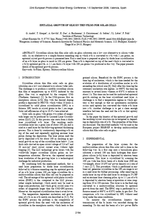
EPITAXIAL GROWTH OF SILICON THIN FILMS FOR SOLAR CELLSG. Andrä1, T. Gimpel1, A. Gawlik1, E. Ose1, A. Bochmann1, S. Christiansen1, G. Sáfrán2, J.L. Lábár2, F. Falk11Institute of Photonic TechnologyAlbert-Einstein-Str. 9, 07745 Jena, Phone (+49) 3641 206438, FAX (+49) 3641 206499, email fritz.falk@ipht-jena.de2Hungarian Academy of Sciences, Research Institute for Technical Physics and Materials Science, 1121 Budapest, Konkoly-Thege M út 29-33, HungaryABSTRACT: Crystalline silicon thin film solar cells on glass substrates are a low cost alternative to silicon wafer cells. As an alternative to a simple furnace annealing step in which a-Si is converted to c-Si with 1 µm grains, an epitaxial crystal growth process is presented here. First a seed layer is prepared on glass by diode laser crystallization of an a-Si layer on glass to result in 100 µm grains. Then a-Si is deposited on top of the seed which is converted to c-Si by epitaxial growth. A 1.1 µm thick c-Si layer with 100 µm grains was produced in this way. The paper presents details of the epitaxial growth process.Keywords: Si-Films, Epitaxy, Multicrystalline Silicon1 INTRODUCTIONCrystalline silicon thin film solar cells on glass substrates are a low cost alternative to silicon wafer cells. The challenge is to produce a suitable crystalline silicon thin film at temperatures up to 650°C endured by the glass. One way is employed by the company CSG (Thalheim, Germany) [1]. In the CSG-process first an amorphous silicon (a-Si) film with the desired doping profile is deposited by PECVD, which within 18 hours is crystallized by solid phase crystallization (SPC) in a furnace. SPC results in crystal grains in the 1 µm range. Solar cell efficiencies of up to 10.4% were achieved.Solar cells on glass with grains two orders of magni-tude larger can be produced by Layered Laser Crystalli-zation (LLC) [2]. In this process one starts from a diode laser crystallized a-Si layer. The resulting multi-crystalline layer has a grain size of about 100 µm and is used as a seed layer for the following epitaxial thickening process. This is done by continuously depositing a-Si on top of the seed and repeatedly applying excimer laser pulses during the deposition. The laser pulses melt the newly deposited a-Si for about 100 ns resulting in epi-taxial growth on top of the crystalline layer below. 2 µm thick cells showed an open circuit voltage of 514 mV and 20 mA/cm² short circuit current even without light trapping [3]. The LLC technology gives layers with the worldwide largest crystalline silicon grains on low temperature substrates. However, the repeated excimer laser irradiation of the growing layer is a technological challenge for industrial production.By combining both the mentioned methods, that is seed layer preparation by diode laser crystallization followed by a furnace annealing step for epitaxial growth of an a-Si layer system 100 µm large crystallites for a multicrystalline silicon thin film cell can be prepared as well. The advantage of this epitaxial solid phase crystalli-zation (ESPC) is the, compared to the LLC process, rather simple technology, which easily may be used in large scale production, and which gives crystal sizes two orders of magnitude larger than the CSG-SPC-process. Moreover, the required crystallization time is even lower.The temperature dependent nucleation and growth rates of c-Si in an a-Si matrix are described in [4,5]. For the ESPC process the problem is the competition of epitaxial growth from the seed with the nucleation of crystallites in the amorphous matrix, which leads to fine grained silicon. Beneficial for the ESPC process is the time lag of nucleation, which is the time needed for the evolution of a distribution of crystalline nuclei in a-Si exceeding the critical size [6]. Only after this time lag the stationary nucleation rate applies. At 600°C the time lag amounts to several hours whereas at 650°C it reduces to about 1 h. This time can be used for undisturbed epitaxial growth starting on the laser crystallized seed layer. A challenge is to find a temperature regime in which epi-taxy is fast enough so that no spontaneous nucleation occurs until epitaxy has converted the whole a-Si layer into c-Si. Another challenge is to get a clean enough interface between the seed and the a-Si so that epitaxy may occur.In the paper the kinetics of the epitaxial growth and the resulting crystal structure are investigated as depend-ing on deposition rate of a-Si. The properties of the films are discussed. The described methods will be used in the European project HIGH-EF to develop multicrystalline silicon thin film solar cells on glass.2 EXPERIMENTALThe preparation of the layer system for the multicrystalline silicon thin film solar cell is done in the following way. In a first step onto a borosilicate glass substrate a several 100 nm thick hydrogen free amor-phous silicon (a-Si) layer is deposited by electron beam evaporation. This layer is crystallized by scanning the 100 µm wide line focus beam of a diode laser (806 nm wavelength, about 10 kW/cm² power density) at a rate of 5 cm/s [2,7]. This procedure, which is performed in am-bient air, generates crystallites in the 100 µm range to act as a seed layer for further processing. After removing an oxide layer on top of the seed layer by etching in 2% HF and an excimer laser cleaning pulse, up to 1.1 µm of a-Si is deposited by electron beam evaporation at rates rang-ing from 10 to 230 nm/min. This layer is in the final step converted to a multicrystalline structure by epitaxial growth from the seed. The EPSC step is performed by a furnace anneal at 600°C or 650°C under Ar gas flow. For comparison, a-Si was crystallized by SPC without seed layer under the same conditions.To monitor the crystallization kinetics the transmission of the Si layers was recorded during the annealing. To this end the beam of a low power HeNelaser (632 nm wavelength) was introduced into the furnace. After passing the sample the transmitted intensity was recorded by a photodiode outside the furnace. The crystal structure after crystallization was investigated by transmission electron microscopy (TEM) and by EBSD (electron back scattering diffraction) which gives orientation maps of the crystal structure in a surface region of the sample.3 RESULTSThe typical fine grained crystal structure following from furnace SPC of a-Si on glass is shown in Fig. 1. The grain size is below 2 µm with no preferential crystal orientation. Fig. 2 shows the evolution of the trans-mission during the annealing which reflects the kinetics of the crystallization. As is obvious a remarkable in-crease of transmission due to an increasing amount of crystalline parts in the film starts after about 6 h. This is a hint for the time lag of nucleation. After the time lag a sigmoidal increase of transmission and of crystal content occurs due to nucleation and growth of crystallites. After about 10 h complete crystallization is achieved.Figure 1: EBSD map of a 1.1 µm thick a-Si layer on glass deposited at 100 nm/min and SPC crystallized by annealing at 600°C for 11 h.Figure 2: Evolution of transmission of an a-Si layer on glass deposited at 100 nm/min during annealing at 600°CIt turned out that the time lag of nucleation as well as the time needed for complete crystallization of a-Si deposited by electron beam evaporation depends on the deposition rate. This is shown in Fig. 3 for an annealing temperature of 600°C. Of particular interest is the time lag which varies between 6 and 25 h.Figure 3: Time lag of nucleation and time for complete crystallization of a 500 nm thick a-Si layer on glass for annealing at 600°C as depending on the deposition rate.In contrast to SPC the epitaxial growth experiments on top of a laser crystallized seed layer lead to much larger crystallites. Fig 4 shows the EBSD map of a seed layer which demonstrates that it consists of grains in the 100 µm range. There is no preferred crystal orientation.Figure 4: EBSD map of a diode laser crystallized seed layer on glass.Fig. 5 shows the evolution of the transmission during EPSC of a 500 nm thick a-Si layer at 600°C which was deposited at a rate of 100 nm/min on top of a laser crystallized seed layer on glass. There is no time lag in epitaxial growth. Instead from the beginning a nearly linear increase of transmission and therefore of crystal amount is observed. After 5.5 h the crystallization is complete. This is less than the time lag of nucleation atthe same temperature. Therefore one does not expect thatnuclei form in the a-Si matrix during the time needed for epitaxial growth.The complete transformation to large grains up to the surface is confirmed by the EBSD map of a 500 nm thick layer, which was taken after 5.5 h annealing at 600°C (Fig. 6). This Figure demonstrates that all grain orientat-ions present in the seed grew epitaxially to the surface. Fig. 7 shows a corresponding TEM cross section image of a 550 nm thick ESPC layer on a seed layer demonstrating that perfect epitaxy occurred. For this to occur a perfectly clean surface of the seed prior to a-Si deposition is crucial.Figure 5: Evolution of transmission of a 500 nm thick a-Si layer deposited at 90 nm/min on a seed layer during annealing at 600°C.Figure 6: EBSD map of a layer system of a 500 nm thick ESPC layer annealed for 5.5 h at 600°C on top of a laser crystallized seed.As for SPC also in ESPC the time needed for complete crystallization, i.e. the epitaxial growth speed, depends on the deposition rate of the a-Si (Fig. 8).Comparing the time needed for ESPC with the time lag (Fig. 3), both as depending on deposition rate, we learn that for 500 nm thick a-Si film at 600°C epitaxial growth is completed within the time lag of nucleation independent of the deposition rate. To completely epitaxially crystallize layers thicker than 500 nm one needs a-Si layers in which the time lag as well as the epitaxial growth speed are as large as possible. This requires a-Si films deposited at rates of about 200 nm/min. In this case the time lag of 14 h is larger than the time needed for epitaxial growth even for a 1µm thick film. Fig. 9 shows the EBSD image of a 1.1 µm thick film crystallized by ESPC at 600°C for 12 h. As for the thinner films large crystals extend up to the surface. Figure 7: TEM cross section image of a layer system consisting of ESPC layer (Si2) on seed (Si1) after annealing for only 7 h at 600°C.Figure 8: Time needed for complete ESPC of a 500 nm thick a-Si layer on top of a seed at an annealing temperature of 600°C.An appreciable reduction in the processing time can be achieved by increasing the annealing temperature. Fig.10 shows the evolution of transmission of a 500 nm thick a-Si layer on a crystalline seed during ESPC at 650°C. The change in transmission immediately starts as is typ-ical for epitaxial growth. After about 1 h the crystalliz-ation is complete. The EBSD map of Fig. 11, however, shows that not all grains of the seed continue to the surface. This is confirmed by the TEM cross section image of Fig 12, where on top of the seed (Si1) about 100 nm of the deposited a-Si epitaxially crystallized (Si2) but the remaining a-Si on top was concerted to fine grained material (Si3). Apparently a competing nucleat-ion process took place in a surface near region. As for the annealing process at 600°C the nucleation and growthkinetics depend on the deposition rate of a-Si.Figure 9: EBSD map of a 1 µm thick ESPC layer deposited at a rate of 180 nm/min and crystallized by annealing at 600°C for 12 h.Figure 10: Evolution of transmission of a 500 nm thick a-Si film on crystalline seed during annealing at 650°C. Figure 11: EBSD map of a 500 nm thick ESPC layer deposited at 47 nm/min and annealed at 650°C for 1.5 h.Figure 12: TEM cross section image of an ESPC layer on seed (Si1) annealed at 650°C for 6 h showing an epitaxially crystallized layer (Si2) and a fine grained layer (Si3).In further work we will investigate if we can deposit a-Si under conditions so that at temperatures between 600°C and 650°C perfect epitaxial growth is possible.4 SUMMARYa-Si layers deposited by electron beam evaporation on top of multicrystalline seed layers on glass were crystallized epitaxially at 600°C up to a thickness of 1.1 µm. In this way we succeeded in preparing a layer system as required for multicrystalline silicon thin film solar cells on glass with grains in the 100 µm range. The preparation process is simple and easily can be up-scaled. By optimizing the deposition and growth conditions we work on reducing the required annealing time and to increase the thickness of the epitaxial layers to well above 1 µm. First observations give hints, that doped a-Si grows faster so that thicker films can be crystallized in even shorter time. In the next steps we will prepare complete solar cells in ESPC silicon layers.5 ACKNOWLEDGEMENTThis paper describes work undertaken in the context of the HIGH-EF project, “Large grained, low stress multicrystalline silicon thin film solar cells on glass by a novel combined diode laser and solid phase epitaxy pro-cess”. HIGH-EF is a Small Scale Collaborative Project supported by the European 7th Framework Programme, contract number 213303.6 REFERENCES[1] M.J. Keevers, T.L.Young, U.Schubert, M.A.Green,Proceedings 22nd European Photovoltaic SolarEnergy Conference (2007), 1783.[2] G. Andrä, J. Plentz, A. Gawlik, E. Ose, F. Falk, K.Lauer, Proceedings 22nd European PhotovoltaicSolar Energy Conference (2007), 1967.[3] G. Andrä, C. Lehmann, J. Plentz, A. Gawlik, E. Ose,F. Falk, 33rd IEEE Photovoltaic Specialists Con-ference (2008), San Diego.[4] U. Köster, phys. stat. sol.(a) 48 (1978), 313.[5] G. Andrä, F. Falk, phys. stat. sol. (c) 5 (2008), 3221.[6] D. Kashchiev, Surf. Sci 14 (1969), 209.[7] G. Andrä, A. Bochmann, F. Falk, A. Gawlik, E. Ose,J. Plentz, 21st European Photovoltaic Solar EnergyConference (2006), 972.。
四层三结双极型晶体管制造流程英文回答:The manufacturing process of a four-layer three-junction bipolar transistor involves several steps. Let me walk you through the process.1. Epitaxial Growth: The first step is to grow a thin layer of semiconductor material on a substrate. This is done through a process called epitaxy. For example, in the case of a silicon transistor, a layer of silicon is deposited on a silicon wafer.2. Base Diffusion: In this step, impurities are introduced into the epitaxial layer to create the base region of the transistor. The impurities are diffused into the silicon substrate using techniques such as ion implantation or thermal diffusion. This step determines the conductivity and doping concentration of the base region.3. Emitter Diffusion: Similar to the base diffusion, impurities are introduced into the base region to create the emitter region. The doping concentration of the emitter region is higher than that of the base region, which allows for the desired transistor characteristics.4. Collector Diffusion: In this step, the collector region is formed by introducing impurities into the substrate. The doping concentration of the collector region is usually lower than that of the base region.5. Metallization: After the diffusion steps, metal contacts are added to the transistor structure to provide electrical connections. These metal contacts are typically made of materials such as aluminum or gold. The metal contacts are patterned using photolithography techniques to ensure proper alignment and contact with the transistor regions.6. Passivation: To protect the transistor from external influences and improve its reliability, a passivation layer is deposited on top of the transistor structure. This layeracts as a barrier against moisture, contaminants, and mechanical stress.7. Packaging: Once the transistor is fabricated, it needs to be packaged to provide electrical connections and protect it from environmental factors. The transistor is typically mounted on a lead frame and encapsulated in a plastic or ceramic package. The package also provides mechanical support and heat dissipation for the transistor.中文回答:四层三结双极型晶体管的制造流程包括多个步骤。
铝合金的熔炼与铸造(Melting and casting of aluminum alloy)Melting and castingMelting and pouring of aluminum alloy is the main link in casting production. The whole process of melting and casting is strictly controlled, which plays an important role in preventing casting defects such as pinholes, inclusions, castings, cracks, porosity and shrinkage. Because the aluminum melt absorbs the hydrogen tendency, the oxidation ability is strong, dissolves the iron easily, in smelting and the casting process, must take the simple and careful preventive measure, obtains the high-quality casting.1 、 preparation and quality control of aluminum alloy burdenIn order to smelt high quality aluminum melt, the qualified raw material should be selected first. To carry out scientific management and proper processing of raw materials, otherwise it will seriously affect the quality of the alloy, the production practice has proved that the raw materials (including metal materials and auxiliary materials) lax control will make batch scrap castings.(1) raw materials must have qualified chemical composition and organization, and the specific requirements are as follows:In addition to the analysis of the main components and impurities in the alloy ingots, the microstructure and fracture of the alloy were examined. Practice has proved that the use of serious shrinkage cavity, pinhole, and bubbles of aluminum liquid, it is difficult to obtain dense castings, and even causethe whole furnace, batch castings scrapped.It was found in the study of Al Si alloy ingots of Aluminum Alloy pinhole, does not appear in the molten pure sand casting pinhole test block, when the aluminum silicon alloy ingot with low and unqualified specimens, pinhole serious, and the grain size large. The reason is the heredity of the material. The heredity of Al Si alloy and heredity increased with the increase of content and the amount of silicon reached 7%. Continue to increase silicon content to eutectic component, heredity decreases slightly again. In order to solve the casting defects caused by the heredity of the burden, aluminum ingots, intermediate alloys and other charging materials with high metallurgical quality must be selected. Specific standards are as follows:(1) there should be no pinholes or holes in the fracture surfacePinhole shall be within grade three, and local (not exceeding 25% of the inspected area) shall not exceed three grade. Over three grade shall be taken by means of heavy smelting to reduce the degree of puncture. Remelting refining method and the general Aluminum Alloy smelting, casting temperature should not exceed 660 degrees, for the original grain large aluminum ingot, alloy ingot, should be the first to use the lower mold temperature, making them rapid solidification, grain refinement.2 、 burden treatmentBefore using the burden, it should be treated by blowing sandto remove the surface rust, grease and other dirt. The time is not long, Aluminum Alloy ingot and metal scrap surface is clean without blowing sand, but should be in charge of the elimination of mixed iron filters and inserts, all shall be in charge of preheating furnace, to remove the surface of the water, shorten the melting time in 3 hours above.3 、 management and storage of burdenReasonable storage and management of burden is important to ensure the quality of alloy. The burden shall be stored in a dry warehouse with little change in temperature.2 、 preparation of crucible and melting tools(1) crucible casting aluminum alloy commonly used iron crucible, also can use cast steel and steel plate welding crucible.New and old is not for a long time in the crucible crucible, before use should be blowing sand, and heated to 700--800 degrees, to keep 2--4 hours, to burn water and attached to the inner wall of the crucible of combustible material, to be cooled to 300 degrees below, carefully clean the inside of the crucible, at a temperature not lower than 200 degrees when spraying paint.The crucible should be preheated to dark red (500--600 degrees) before use and kept warm for more than 2 hours. Before the new outer crucible melting, melting scrap with the best grades of a furnace.(two) preparation of smelting toolsZhong Zhao, press ladle, mixing spoon, ladleAt the other before use shall be preheated, and at 150 degrees ---200 degrees temperature, coated with a protective coating, and thorough drying, the drying temperature is 200--400 degrees, holding time of 2 hours, after use should be thoroughly removed attached on the surface of oxide and fluoride (preferably blowing sand).3, smelting temperature controlThe melting temperature is too low, is not conducive to the dissolution of alloying elements and gas inclusions, discharge, tendency segregation, cold shut, undercasting increase formation, but also because of insufficient heat riser, the casting without reasonable feeding, has information that,The melting temperature of all aluminum alloys should be up to 705 degrees and should be stirred. The melting temperature is too high, not only a waste of energy, more serious is because the higher the temperature, the hydrogen absorption of the grain becomes thick, aluminum oxide is more serious, some of the burning loss of alloy elements is more serious, which leads to a decrease in the mechanical properties of the alloy, casting the deterioration of mechanical properties and modification, weaken the effect of air the castings reduce.The production practice shows that the molten alloy rapid heating to high temperature, reasonable stirring to dissolve all alloy elements (especially refractory metals), scrapingscum down after the pouring temperature, so that the minimum degree of segregation, melting of hydrogen is less favorable, to obtain the uniform and compact alloy mechanical properties high. Because the aluminum melt temperature is difficult to determine with the naked eye, so no matter what type of the melting furnace, should use temperature control instrument. The instrument should be regularly checked and the maintenance cycle should thermowell with metal brush clean, coated with a protective coating, in order to ensure the accuracy and prolong the service life of the measurement result.4 、 control of smelting timeIn order to reduce the oxidation, gettering and dissolution of molten aluminum, the residence time and rapid melting of molten aluminum should be shortened. From the beginning of the melt to the end of the casting, the sand casting shall not exceed 4 hours, the die casting shall not exceed 6 hours, and the die casting shall not exceed 8 hours.In order to speed up the smelting process, should first join the scrap aluminum silicon intermediate alloy medium size, low melting point, in order to accompany the formation of molten pool as soon as possible in the crucible bottom, then add the returns for larger pieces and pure aluminum ingot, so that they can gradually expand slowly immersed in molten pool, fast melting. When the main part of the furnace is melted, the intermediate alloy with higher melting point and small quantity is melted and stirred to accelerate the melting. Finally, cool down and press the oxidizable alloy elements to reduce the loss.5, melt transfer and pouringAlthough the density of the solid alumina is similar to the density of the aluminum melt, it will take a long time to sink to the bottom of the crucible after entering the interior of the molten aluminum. Alumina film is oxidized and aluminum melt formation, but only in contact with the molten aluminum side is dense, and exposed to the air side loose and there is a lot of 60--100A diameter holes, its large surface area, strong adsorption, easy adsorption in water vapor, the tendency of anti floating. Therefore, in this film and aluminum melt proportion difference is small, be mixed with the melt, and the speed is very slow, it is difficult to exclude from the melt, porosity inclusion formation in castings too. Therefore, the key to transfer aluminum melt is to minimize the agitation of molten metal and minimize the contact between the melt and the air.By tilting the crucible melt injection, in order to avoid mixing melt and air, should be as far as possible by the ladle furnace nozzle, and inclined, melt down along the side wall of the ladle, no direct impact on the bottom of the bag, occurrence of agitation, splash.The proper and reasonable pouring method is one of the important conditions to obtain high quality castings. In the production practice, it is effective to prevent and reduce casting defects by paying attention to the following items.(1) the temperature of the melt, the capacity of the ladle and the degree of dryness of the coating on the surface shall beexamined carefully before pouring, and whether the preparation of other tools meets the requirements or not. The metal gate Cup before casting 3--5 minutes in the sand on a good place, the ladle with the temperature less than 150 degrees for premature or excessive temperature, pouring tract hold large amounts of gas, there is a danger of explosion when pouring.(two) not in the "draught" casting occasions, as well as strong melt oxidation, combustion, the casting defects such as oxide inclusions.(three) obtained by melt in the crucible, should first use of bottom oxide layer or the flux through gently melt surface, slowly immersed in the melt with the ladle, ladle a wide mouth melt, and then gently lift the ladle.(four) the end of the package should not be flat; the pace should be steady; the ladle should not be raised too high; the metal level in the ladle must be stable and free from movement.(five) to be cast, with net ladle slag should be,In order to avoid pouring slag, oxide, etc. into the mold.(six) in the casting, the melt flow is stable, can not be interrupted, not into the mouth with the bottom. Sprue should be full from beginning to end, liquid level shall not turn, casting speed should be properly controlled. Usually, the casting starts slightly slower, filling the melt, stabilizing it, then slightly faster, and keeping the casting speed constant.(seven) in the pouring process, pouring ladle and gate distance as close as possible, not more than 50 mm limit, so as not to melt too much oxidation.(eight) with a blocked gate, the plug cannot be dialed too early. After the melt has filled the gate, it is slowly tilted out so as to prevent the melt from producing eddy current when it is injected into the sprue.(nine) the melt less than 60 mm from the bottom of the crucible shall not be poured into the casting.Aluminum alloy casting (ZL)According to the main elements other than aluminum, silicon, copper, magnesium and zinc are divided into four kinds, and the codes are 100, 200, 300 and 400 respectively.In order to obtain high quality precision castings of various shapes and specifications, aluminum alloys for casting usually have the following characteristics.(1) a narrow slot filled with good liquidity part(2) there is a melting point lower than that of a general metal, but it can meet most of the requirements(3) the thermal conductivity is good, the heat of molten aluminum can be transferred rapidly to the mold, and the casting cycle is shorter(4) hydrogen and other harmful gases in the melt can be effectively controlled by treatment(5) Aluminum Alloy casting, no cracking and tearing cracking tendency(6) good chemical stability and strong corrosion resistance(7) it is not easy to produce surface defects, the casting surface has good surface finish and gloss, and easy to surface treatment(8) Aluminum Alloy casting processing performance is good, can die, die, sand and dry sand mold, gypsum type casting casting, vacuum casting, can also be used for low and high pressure casting, extrusion casting, semi-solid casting, centrifugal casting forming method, with different purposes, different varieties of production specifications and different properties of various castings.Cast aluminum alloy has been widely used in cars, such as cylinder head, intake manifold, piston, wheel hub, steering booster housing, etc.。
Wet-Chemical Etching and Cleaning of SiliconJanuary 2003Virginia Semiconductor, Inc.1501 Powhatan Street, Fredericksburg, VA 22401(540) 373-2900, FAX (540) 371-0371, tech@A IntroductionResearch and manufacturing related to silicon devices, circuits, and systems often relies on the wet-chemical etching of silicon wafers. The dissolution of silicon using liquid solutions is needed for deep etching and micromachining, shaping, and cleaning. Also, wet-chemistries are often used for defect delineation in single crystal silicon materials. In this paper, a review of the typical wet-chemical recipes used by engineers is given. As many sources as possible have been used to present a concise listing of etchants and processes.B Wafer CleaningA sequence of chemistries is typically used to clean silicon wafers. This sequence was first developed at the RCA laboratories, and is therefore often referred to as the RCA process. This chemical sequence does not attack the silicon material, but selectively removes the organic and inorganic contamination that resides on the wafer surface. The following is a typical RCA process; many variations to the ordering of the sequence and chemical ratios are used throughout the industry.• General Clean: A general cleaning is accomplished by using a mixture of Sulfuric Acid and Hydrogen Peroxide. Mixing these chemicals is dangerous and generates extreme heat. This industry standard clean removes organic and inorganiccontamination from the wafer. 2-10 minute clean is recommended. Strong rinsein DI water is required after this cleaning step.• Particle Removal: A Megasonic clean (at about 70 C) in a 5:1:1 ratio mixture of DI water: Ammonium Hydroxide : Hydrogen Peroxide will remove silica andsilicon particles from the wafer, as well as remove certain organic and metalsurface contamination. 2-10 minute clean is recommended. Strong rinse in DIwater is required after this cleaning step.• Oxide Removal: A 15-60 second dip in 1:20 HF:DI water will remove the native oxide layer and any contamination in the oxide from the wafer surface. HF isextremely dangerous and must be handled with great care. Strong rinse in DIwater is required after this cleaning step.• Metal Contamination Removal: A Megasonic clean (at about 70 C) in a 6:1:1 ratio mixture of DI water: HCL : Hydrogen Peroxide will remove certain ionicand metal surface contamination. 2-10 minute clean is recommended. Strongrinse in DI water is required after this cleaning step.• Spin Rinse Dry: Wafers should be rinsed and dried in a standard spin-rinse dryer.Megasonic agitation is commonly used with the chemical bath and most commonly withthe particle removal step. Also, heavy DI rinse steps are used between each chemical treatment. DI rinsing may use dump-baths, over-flow baths, and spray-dump baths, aswell as combinations. Proper removal of all cleaning chemistry with 18MegaOhm DIwater is critical and needed after each chemical bath. Any text book on the topic of semiconductor or silicon processing is an excellent resource for further informationregarding the RCA cleaning process ( for example see S.Wolf and R. Tauber, “Silicon Processing:Vol.1”, Lattice Press, CA, 1986).There are commercially available premixed cleaning solutions that can be used directly toclean wafers and serve the same purpose of the RCA cleaning process. These chemicals typically achieve the function of several cleaning steps with one solution (see forexample JT Baker, Baker Clean Solution).C Anisotropic KOH EtchingKOH is one the most commonly used silicon etch chemistry for micromachining silicon wafers.1. Anisotropic KOH Etching Rates vs. OrientationThe KOH etch rate is strongly effected by the crystallographic orientation of thesilicon (anisotropic). Table 1 relates silicon orientation-dependent etch rates (µmmin-1) of KOH to crystal orientation with an etching temperature of 70°C. Table1 is taken directly from [1]. In parentheses are normalized values relative to(110).CrystallographicRates at different KOH ConcentrationOrientation 30% 40% 50% (100) 0.797 (0.548) 0.599 (0.463) 0.539 (0.619)(110) 1.455 (1.000) 1.294 (1.000) 0.870 (1.000)(210) 1.561 (1.072) 1.233 (0.953) 0.959 (1.103)(211) 1.319 (0.906) 0.950 (0.734) 0.621 (0.714)(221) 0.714 (0.491) 0.544 (0.420) 0.322 (0.371)(310) 1.456 (1.000) 1.088 (0.841) 0.757 (0.871)(311) 1.436 (0.987) 1.067 (0.824) 0.746 (0.858)(320) 1.543 (1.060) 1.287 (0.995) 1.013 (1.165)(331) 1.160 (0.797) 0.800 (0.619) 0.489 (0.563)(530) 1.556 (1.069) 1.280 (0.989) 1.033 (1.188)(540) 1.512 (1.039) 1.287 (0.994) 0.914 (1.051)(111) 0.005 (0.004) 0.009 (0.007) 0.009 (0.010)The (110) plane is the fastest etching primary surface. The ideal (110) surface hasa more corrugated atomic structure than the (100) and (111) primary surfaces.The (111) plane is an extremely slow etching plane that is tightly packed, has asingle dangling-bond per atom, and is overall atomically flat. As shown above,the strongly stepped and vicinal surfaces to the primary planes are typically fastetching surfaces.2. KOH Etching Rates vs. Composition and TemperatureTable 2 relates silicon orientation-dependent etch rates of KOH to percent composition, temperature, and orientation. Table 2 is taken directly from [2]. As with all wet-chemical etching solutions, the dissolution rate is a strong function of temperature. Significantly faster etch rates at higher temperatures are typical, but less ideal etch behavior is also common with more aggressive etch rates. Also, heavy boron doping can significantly harden the silicon and sharply reduce the etch rate.Etchant Temperature (°C) Direction(plane) Etch rate (µm min -1) Remarks Reference20% KOH: 80% H 2O 204060 80 100(100) (100) (100) (100) (100)0.025 0.188 0.45 1.4 4.1 Near Peak etch rate at the conc. across temperature [3] 30% KOH: 70% H 2O 20 4060 80 100 20 40 60 80 100(100) (100) (100) (100) (100) (110) (110) (110) (110) (110) 0.024 0.108 0.41 1.3 3.8 0.035 0.16 0.62 2.0 5.8 Smoother surfaces than at lowerconcentrationFaster etch rate for (110) than for (100)[3]40% KOH: 60% H 2O2040 60 80 100(100) (100) (100) (100) (100) 0.020 0.088 0.33 1.1 3.1 [3]20% KOH: 80% 4H 2O: 1IPA)2040 60 80 100(100) (100) (100) (100) (100)0.015 0.071 0.28 0.96 2.9Lower etch rateSmoother Lessundercutting Lower (100) : (111) etch-rate ration [3]44% KOH: 56% H 2O 120 (100) (110)(111)5.8 11.7 0.02 HighTemperature[4]23.4% KOH: 63.3%H2O: 13.3% IPA 80 (100)(110)1.00.06Sensitive toboronconcentration[5]D Anisotropic TMAH (tetramethylammonium hydroxide) EtchingSimilar to KOH etching, TMAH is commonly used for fast removal and silicon micromachining.1. TMAH Etching Rates vs. OrientationThe orientation dependence of the TMAH etch rate is similar to KOH and variessimilarly in accordance to the atomic organization of the crystallographic plane.Table 3 relates silicon orientation-dependent etch rates of TMAH (20.0wt%,79.8°C) to orientation. Table 3 is taken directly from [6].Etching rate ratioOrientation Etching rate (µmmin-1) (i j k)/(100) (i j k)/(111)100 0.603 1.000 37110 1.114 1.847 68210 1.154 1.914 70211 1.132 1.877 69221 1.142 1.894 69310 1.184 1.964 72311 1.223 2.028 74320 1.211 2.008 73331 1.099 1.823 67530 1.097 1.819 66540 1.135 1.882 69111 0.017 0.027 12. TMAH Etching Rates vs. Composition and TemperatureSimilar to KOH, the TMAH etch rate varies exponentially with temperature.Table 4 relates silicon orientation-dependent etch rates of TMAH to percentcomposition, temperature, and orientation. Table 4 is taken directly from [2].Etchant Temperature (°C) Direction (plane) Etchrate(µm min -1) Remarks Resources5% TMAH: 95% H 20 60708090607080906090 (100) (110) (111) 0.33 0.48 0.87 1.4 0.64 0.74 1.4 1.8 0.026 0.034 [7]10%TMAH: 90% H 2060708090(100) 0.28 0.41 0.72 1.2 [7] 2% TMAH: 98% H 20 80 (100) (111) 0.65 0.41 [8] 5% TMAH: 95% H 20 80 (100) (111) 0.63 0.013 [8] 10% TMAH:90% H 2080 (100) (111) 0.57 0.014 [8]22% TMAH in H 20 90 (100) (110) (111) 0.9 1.8 0.018 (110) isfastestwithoutsurfactant[9] 22% TMAH in H 20 +0.5%surfactant90 (100)(110) (111) 0.6 0.12 0.01 (100) is fastest with surfactant [9] 22% TMAH in H 20 + 1%surfactant90 (100)(110) (111) 0.6 0.1 0.009 Surfactants effect saturates [9]\E EDPSimilar to KOH, EDP is often used for fast removal and silicon micromachining.Table 5 relates silicon orientation-dependent etch rates in EDP solutions to Temperature and Orientation.Etchant Temperature (°C) Direction (plane) Etch rateRemarks Reference(µm min-1)500 mlNH2(CH2)2NH2: 88g C6H4(OH) 2: 234 ml H20 110 (100)(110)(111)0.470.280.028EDP ‘T’ etchOldest EDPformulaER rises to >0.83 µm/minafter exposure tooxygen[10]500 mlNH2(CH2)2NH2: 160g C6H4(OH) 2: 160 ml H20 115 (100) 0.45 EDP ‘F’ etchFast etch rateMust be used athigh T to avoidresidue[11]F etch above w/1.0g C6H4N2115 (100) Fasterw/pyrazineLess sensitive tooxygenSmoother[11]F etch above w/3.0g C6H4N2115 (100)1.35 [11]500 mlNH2(CH2)2NH2: 80g C6H4(OH) 2: 3.6 C6H4N2 : 66ml H20 507595105110(100)(100)(100)(100)(100)0.0750.220.430.570.75EDP ‘S’ etchSlower etch rateSuitable forlowertemperature usewithout residue[11]46.4 mol%NH2(CH2)2NH2: 4 mol% C6H4(OH)2: 49.4 mol% H20118 (100)(110)(111)Stops on p++ [12]250 mlNH2(CH2)2NH2: 45g C6H4(OH) 2: 120ml H20 110 (100)(111)[13]F Isotropic Silicon EtchesOften, isotropic etchants having dissolution rates independant of orientation are needed.These chemical mixtures tend to uniformly remove material, and are limited by the masstransport of chemical species to the crystal surface. The actual surface reaction rates areso great that variations to atomic structure do not alter the reaction speed relative tochemical transport.Table 6 lists several common recipes and is taken directly from [14].Formula Comments Reference HF, HNO3 See [14] p73HF, HNO3, H20 or CH3COOH Various combinations give differentetch rates[15]900ml HNO3, 95 ml HF,5ml CH3COOH, 14g NaClO215 µm/min [16]745 ml HNO3, 105 ml HF,75 ml CH3COOH,75 ml HClO4170 A/sec [17]50 ml HF, 50 ml CH3COOH,200 mg KMnO4 (fresh)Epi Etching 0.2 µm/min [18]108 ml HF, 350g NH4F per L H20 Epi Etchingn type 0.2-0.6 ohm-cm; 0.43 A/minp type 0.4 ohm-cm; 0.45 A/minp type 15 ohm-cm; 0.23 A/min[19]G Silicon Defect Delineation EtchesCertain chemical etchants are strongly dependent on defects, and defect structures in the single crystal silicon. These etchants are commonly used to high-light or delineate defects in the material.Table 7 lists the most common defect delineation mixtures, and is taken directly from [14]Formula Name Application ShelfLifeRef1 1 ml HF, 1 ml C2O3 (5M) Sirtl 111 SiliconApprox 5min etch5 min [20]2 1 ml HF,3 ml HNO3,1 ml CH3COOH Dash 111 oe 100 n or p(works best on p)Approx 15 hr etch8 h [21]3 2 ml HF, 1 ml K2Cr2O7(0.15M)2 ml HF, 1 ml Cr2O3(0.15M) SeccoSecco100 or 111 silicon100 or 111 silicon5 min5 min[21][21][20]4 200 ml HF, 1 HNO3P-Ndelineation [20]5 60 ml HF, 30 ml HNO360 ml H2060 ml CH3COOH, 30 ml(1g CrO3 to 2 ml H20) JenkinsWrightgeneral usedoes not roughendefect freeregionsApprox 30 minetch6 wks [21][20][22]6 2 ml HF, 1 ml HNO3, 2ml AgNO3 (0.65M inH20) Silver epitaxiallayerfaults[20]7 5 gm H5IO6, 5 mg Kl in50 ml H2O, 2 ml HF SponheimerMillsEtch 5-20 secondsjunctiondelineation[22]8 Shipley112° [23]9 6 ml HF, 19 ml HNO [23]10 (150g/l (1.5M) CrO3 toH20) to HF 1:1Yang [24]11 600 ml HF, 300 mlHNO3 28g Cu(NO3) 2, 3ml H20 CopperEtch[25]12 1000 ml H2O, 1 drop(1.0N) KOH 3.54g kBr,.708g KbrO3[25]13 55gCuSO4, SH20, 950 ml H20, 50 ml Hf CopperDisplacement[25]14 1 ml HF, 3 ml HNO3White 15 secs. PNJunction etch withstron light15 3 ml HF, 5 ml HNO3,3 ml CH3COOH CP-4 10 sec – 3 minP-N Junctions[26]16a 16b 16c 16d 25 ml HF, 18 ml HNO3,5 ml CH3COOH/.1Br210 ml H20, 1g Cu(NO3) 2100 ml HF; .1 to .5 mlHNO350 ml dilute Cu(NO3) 21 to2 drops HF4% NaOH add 40 NaClOuntil no H2 evolutionfrom SiSD1 2-4 min revealsedge and mixeddislocationsP stainN stain80ºC specimenthinning (floatspecimen onsurface of etch)[26][26][26][26]17 300 ml HNO3, 600 mlHF 2 ml Br2, 24gCu(NO3) 2 dilute 10:1wtih H2O Sailer Etch 4 hr EpiStacking Faults[27]18 a) 1) 75g CrO3 in 1000ml H2O mix 1 part 1) to 2parts 48% HFb) mix part 1) to 2 parts48% HF to 1.5 parts H2O Schimmel Resistivity greaterthan .2 ohm-cm(111) oe (100)approx 5 minResistivity lessthan .2 ohm-cm19 5gH5IO6, 50 ml H2O,2 ml HF, 5mg Kl PeriodicHFJunctionDeliniationH ConclusionThere are many wet-chemical etch recipes known for etching silicon. These processes are used for a variety of applications including micromachining, cleaning, and defect delineation. The detailed behaviour and rate of the etchant will vary between laboratory enviroments and exact processes. However, the data and phenomena recorded above have been reported by many researchers and manufactures.For further details the reader is encourage to fully explore the direct and indirect references sited.I References[1] K. Sato et al.[Characterization of orientation-dependent ethcing properties ofsingle-crystal silicon: effects of KOH concetration(Sensors and Actuators A 64(1988) 87-93)][2] R. Hull [ Properties of Crystalline Silicon (INSPEC, London, 1999)][3] H. Seidel, L. Cseprege, A. Heuberger, H. Baumgarel [ J. Electrochem. Soc. (USA)vol. 137 (1990) p. 3626-32][4] D.L. Kendall [Annu. Rev. Mater. Sci (USA) vol.9 (1979) p.373][5] J.B. Price [Semiconductor Silicon –1973 Eds. H.R. Huff, R.R. Burgess (E;[6] M. Shikida, K. Sato, K. Tokoro, D. Uchikawa [Dept. of Micro SysytemsEngineering, Nagoya University, Japan][7] O. Tabata, R. Asahi, H. Funabashi, K. Shimaoka, S. Sugiyama [Sens. Actuators A(Switzerland) vol. 34 (1992) p.51-7][8] U. Schnakenberg, W. Benecke, P. Lange [Proc. 1991 Int. Conf. Solid-StateSensors and Actuators (Tansducers ’91) San Fransisco, USA, 1991 (IEEE, NewYork, NY, 1991) p.815-8][9] M. Sekimura [ Proc. 12th IEEE Int. Micro-Electrical Mechanical Systems Conf.(MEMS 1999), Orlando, Florida, USA, p.650-5][10] R.M. Finne, D.L. Klein [J. ElectroChem. Soc. (USA) vol. 114 (1967) p.965-70][11] A. Reisman, M. Berkenbilt, S.A. Chan, F.B. Kaufman, D.C. Green [J.ElectroChem Soc. (USA) vol. 126 (1979) p.1406-14][12] E. Bassous [IEEE Trans. Electron Devices (USA) vol.ED-25 (1978) p.1178][13] G. Kaminsky [J. Vac. Sci. Technol. B (USA) vol.3(1985) p.1015][14] S. Walsh[ Wetch Etching fo Semiconductor Fabrication, Janus Ventures Inc.][15] B. Schwartz, H. Robbins [J. ElectroChem Soc. 10B, 365 (1961)][16] A. Stoller, R. Speers, S Opresko [ RCA Rev 31, 265 (1970)][17] R. Blaha, W. Fahrner[J. ElectroChem Soc 123, 515 (1976)][18] M. Theunissen, J. Apples, W Verkuylen [J. ElectroChem Soc 117, 959 (1970)][19] W. Hoffmeister int. [J. Appl Radiat Isot 2, 139 (1969)][20] S. Ghandi [ “VLSI Fabrication Principles” , Wiley InterScience (1983)][21] K. Ravi [ “Imperfections and impurities in Semiconductor Silicon”, Wiley (1981)][22] T. Mills, E. Sponheimer [ Precision VLSI Cross Sectioning and Staining” 1982IEEE Proceedings][23] D. Elliot [ “Integrated Circuit Fabrication Technology”, McGraw-Hill (1982)][24] “Semi Spec Identification of Structures and Contaminents seen on SpecularSilicon Surfaces” ASTM[25] M. Jacques, [“The Chemistry of Failure Analysis”, IEEE EDM (1979)][26] J. Heiss Jr., J. Wylie, U.S. Patent 4,089,704 (1978)[27] T. Chu, R. Keim Jr.[ J. ElectroChem Soc. 122, 995 (1975)。
Adv.Mater.2005,17,2521www.advmat.de©2005WILEY-VCH Verlag GmbH &Co.KGaA,Weinheim2521How to contact us:Editorial Office:Telephone:(+49)6201606235/432Fax:(+49)6201606500E-mail:advmat@wiley-vch.de Reprints:Agnes PetersenTelephone:(+49)6201606218Fax:(+49)6201606500E-mail:advmat@wiley-vch.de Copyright Permission:Telephone:(+49)6201606280Fax:(+49)6201606332E-mail:rights@wiley-vch.de Subscriptions:Telephone:(+49)6201606400Fax:(+49)6201606184E-mail:service@wiley-vch.de Advertising:Fax:(+49)6201606500E-mail:advmat@wiley-vch.de Courier Services:Boschstrasse 12,69469Weinheim,GermanyRegular Mail:Postfach 101161,69451Weinheim,GermanyAdvanced Materials has been publishing the latest progress in materials science for more than 15years.With an indepen-dently assessed ISI Impact Factorof 8.079,Advanced Materials continues to deliver the highest quality research reports every two weeks.It containscarefully selected,top-quality reviews,communications,and research news at the cutting edge of the chemistry and physics of functional materials as well as book reviews,product information,interviews,and a conference calendar.From 2005our new sister journal‘Small ’,the ideal forum for presenting the very best experimental andtheoretical studies of fundamental and applied research at the micro and nano scales,is being delivered monthly with Advanced Materials .www.advmat.deCover:The automated synthesis and nano-mechanical characterization of discrete combinatorial arrays of polymersenables high-throughput discovery and analysis of compliant,functional materi-als,as shown by Van Vliet and co-work-ers on p.2599.The cover illustrates a triplicate array of 576polymers auto-matically printed on a glass microscope slide,where each spot represents a pair-wise,systematically varied composition among 24different monomers.Overlaid on the image of this triplicate array is a differential interference contrast image of a single nanoliter-scale polymer vol-ume.In less than twenty-four hours of synthesis and mechanical characteriza-tion,the stiffness of each polymer is de-termined and related to key monomer structures and volume fractions thereof.Inside Cover:Short,single-particle-wide chains and complex networks of interconnected chains are easily self-assembled from 13nm Au nanoparticles by inducing a surface electrostatic dipolar moment in a controlled manner.Mann andco-workers further demonstrate both experimentally and theoretically on p.2553that efficient surface plasmon coupling takes place in these extensive networks,thus opening a new bottom–up approach to subwavelength optical-waveguiding devices.The left panel in the image shows isolated 13nm Au nanoparticles;the back panel,short linear chains;the bottom panel,com-plex branched network of chains;and the right panel,a graphical rendering of optical spectroscopic properties during the self-assembly process.Editor:Esther Levy Deputy Editor:Karen Grieve Associate Editors:David Flanagan,Cara Mulcahy,Soraya ReidenbachAssistant Editors:Mary Farrell,Lisa WylieProduction:Agnes Petersen Administration:Ramona Nily,Melanie Schmitt,Susanne StollMarketing:Claudia Barzen Freelance Cartoonist:Philip Harms Editorial Office:Tel.(+49)6201606235/432Fax (+49)6021606500E-mail:advmat@wiley-vch.de Subscription Service:Tel.(+49)6201606400Fax (+49)6021606184E-mail:service@wiley-vch.de Order through your bookseller or directly at the Publisher:Wiley-VCH,P .O.Box 101161,D-69451Weinheim,Germany.Tel.(+49)6201606400Fax (+49)6201606184E-mail:service@wiley-vch.de Published 24times a year by WILEY-VCH Verlag GmbH &Co.KGaAD-69469Weinheim,GermanyAdvisory Board P .M.Ajayan,Rensselaer Polytechnic Inst.P .Batail,Angers M.T.Bernius,DowP .W.M.Blom,GroningenP .D.Calvert,Univ.of Massachusetts J.Caro,HannoverJ.H.Fendler,Clarkson S.Forrest,Princeton R.H.Friend,Cambridge R.C.Haddon,UC Riverside P .T.Hammond,MIT A.Hirsch,Erlangen H.van Houten,Philips J.Hulliger,BernT.Hyeon,Seoul Natl.Univ.A.C.Jones,Inorgtech D.L.Kaplan,Tufts T.Kato,Tokyohav,Weizmann Inst.Sci.S.Mann,BristolC.R.Martin,Univ.of Florida R.D.McCullough,Carnegie MellonE.W.Meijer,Eindhoven ler,UtahC.A.Mirkin,Northwestern W.S.Rees,Georgia Tech J.Rieger,BASFM.J.Sailor,UC San Diego F.Schüth,MPI Mülheim Y.Shirota,FukuiM.Steigerwald,Columbia S.Subramoney,DuPont G.Wegner,MPI MainzBooks for review:Uninvited copies not chosen for review will not be returned.Manuscript Submission &PersonalHomepage:Typeset by kühn &weyhSatz und Medien,Freiburg,Germany.Printed by Druckhaus Darmstadt GmbH,Darmstadt,Germany.Printed on acid-free paper.©2005Wiley-VCH Verlag GmbH &Co.KGaA,D-69469Weinheim,Germany.All rights reserved (including those of translation into foreign languages).No part of this issue may be reproduced in any form –by photoprint,microfilm,or any other means –nor transmitted or translated into a machine language without written permission from the publishers.Only single copies of contribu-tions,or parts thereof,may be made for personal use.This journal was carefully produced in all its parts.Nevertheless,authors,editors,and publisher do not guarantee the information contained therein to be free of errors.Registered names,trademarks,ed in this journal,even when not marked as such,are not to be considered unprotected by law.Valid for users in the USA:The copyright owner agrees that copies of the articles may be made for personal or internal use,or for the personal or inter-nal use of specific clients.This consent is given on the condition,however,that the copier pay the stat-ed per-copy fee through the Copyright Clearance Center,Inc.(CCC)for copying beyond that per-mitted by Sections 107or 108of the U.S.Copyright Law.This consent does not extend to other kinds of copying,such as copying for general distribtion,for advertising or promotional purposes,for creating new collective works,or for resale.For copying from back volumes of this journal see ‘Permissions to Photo Copy:Publisher’s Fee List’of theCCC.Annual subscription rates 2006PersonalInstitutional*Europe EUR 298EUR 3078/3386Switzerland SFr 638SFr 4818/5300Outside EuropeUS$418US$3958/4354*Print or electronic delivery/print +electronic delivery First-time personal rates are available on request.10%discount if ordered in combination with Advanced Functional Materials.Postage and handling charges included.For the USA and Canada:ADVANCED MATERIALS (Print ISSN 0935-9648,Online ISSN 1521-4095)is published semimonthly by Wiley-VCH,P .O.Box 101161,D-69451Weinheim,Germany.Air freight and mailing in the USAby Publications Expediting Services Inc.,200Meacham Ave.,Elmont,NY 11003.Periodical postage paid at Jamaica,NY Postmaster:Send address changes to:“Advanced Materials”c/o Wiley-VCH,111River Street,Hoboken,NJ 07030.Adv.Mater.2005,17,2523–2529www.advmat.de©2005WILEY-VCH Verlag GmbH &Co.KGaA,Weinheim2523Upcoming ArticlesG.L.Liu,Y.Lu,J.Kim,J.C.Doll,L.P .Lee*Magnetic Nanocrescents as Controllable Surface-Enhanced Raman Scattering Nanoprobes for Biomolecular ImagingPublished Online:September 29,2005DOI:10.1002/adma.200501064X.Liu,J.Ly,S.Han,D.Zhang,A.Requicha,M.E.Thompson,C.Zhou*Synthesis and Electronic Properties of Individual Single-Walled Carbon Nanotube/Polypyrrole Composite NanocablesPublished Online:September 29,2005DOI:10.1002/adma.200501211S.W.Lee,R.G.Sanedrin,B.-K.Oh,C.A.Mirkin*Nanostructured Polyelectrolyte Mul-tilayer Organic Thin Films Generated via Parallel Dip-Pen Nanolithography Published Online:September 29,2005DOI:10.1002/adma.200501120N.Tétreault,G.von Freymann,M.Deubel,M.Hermatschweiler,F.Pérez-Willard,S.John,M.Wegener,G.A.Ozin*New Route to Three-Dimensional Photonic Bandgap Materials:Silicon Double Inversion of Polymer TemplatesPublished Online:September 26,2005DOI:10.1002/adma.200501674All our articles are available online in advance of print.The articles listed here have been judged by the referees or the editor to be either very important or very urgent and were immediately copyedited,proofread,and published online when the manuscript arrived in the editorial office in its final form.As long as there is no page number available,online manuscripts should be cited in the following manner:Authors,Adv.Mater.,online publication date,DOI.REVIEWNanocrystalsD.Kovalev,*M.Fujii ........2531–2544Silicon Nanocrystals:Photosensitizers for OxygenMoleculesThe features of nanoscale silicon that make it different from the bulk result in very efficient energy transfer from excitons confined in silicon nanocrystals to oxygen molecules following their activation to the highly reactive singlet state (see Figure).The mechanism for the photosensitization of oxygen molecules using silicon nanocrystals is reviewed.We discuss,in addition,the implications of these findings for physics,chemistry,biology,and medicine.COMMUNICATIONSMagnetic MaterialsC.Enkrich,F.Pérez-Willard,D.Gerthsen,J.F.Zhou,T.Koschny,C.M.Soukoulis,M.Wegener,S.Linden*...2547–2549Focused-Ion-Beam Nanofabrication of Near-Infrared MagneticMetamaterialsSplit-ring resonators with a magnetic resonance in the near-infrared have been fabricated using the rapid-prototyping capabilities of focused-ion-beam writing.By varying the design parameters,a continuous transition from a degenerate Mie resonance to a magnetic-dipole response is shown (see Figure).In particular,a negative magnetic permeability at a wavelength of 2.4 m and a negative magneticsusceptibility at a wavelength of 1.7 m are demonstrated.Organic SemiconductorsA.Brillante,*I.Bilotti,R.G.Della Valle,E.Venuti,M.Masino,A.Girlando...2549–2553 Characterization of Phase Purity in Organic Semiconductors by Lattice-Phonon Confocal Raman Mapping: Application toPentacene Lattice-phonon confocal Raman mapping is a powerful technique to probe the crystal structure of poly-morphs of organic semiconductors.This technique is fast,reliable,and capable of monitoring physical modifications and phase inhomogeneities in crystal do-mains at the micrometer scale.Applying the technique to pentacene crystals (see Figure)shows that phase inhomo-geneities are not confined to the crystal surface,but penetrate into the crystal.Nanoparticle AssemblyS.Lin,M.Li,E.Dujardin,*C.Girard,S.Mann*..........2553–2559 One-Dimensional Plasmon Coupling by Facile Self-Assembly of Gold Nanoparticles into Branched ChainNetworks Short chains and complex networks of interconnected Au nanoparticle chains (see Figure)are produced by a simple template-free approach.Optical spectroscopy and computer simulations show that surface plasmons from individual non-contacting nanoparticles are strongly coupled in the resulting1D superstructures.These chains may pro-vide a unique way to fabricate complex subwavelength optical waveguides.NanopatterningJ.H.Moon,S.G.Jang,J.-M.Lim,S.-M.Yang*.......................2559–2562 Multiscale Nanopatterns Templated from Two-Dimensional Assembliesof PhotoresistParticles Multiscale nanopatterns fabricated by colloidal lithography,using two-dimen-sional self-assemblies of photoresist particles as masks,are presented.The colloidal masks with features of multiple length scales are obtained by photolithography and used for con-structing submicrometer-hole arrays over large areas(see Figure).By depositing functional materials through these masks,nanopatterned substrates useful in a wide range of applications can be produced.NanostructuresC.Lu,L.Qi,*J.Yang,X.Wang,D.Zhang,J.Xie,J.Ma.....2562–2567 One-Pot Synthesis of Octahedral Cu2O Nanocages via a Catalytic SolutionRoute Unique single-crystalline octahedralCu2O nanocages(see Figure)are synthesized in solution by the catalytic reduction of copper tartrate complex into octahedral Cu2O nanocrystals and a subsequent spontaneous hollowing process.A wealth of colorful nanostruc-tures with widely tunable bandgaps in the range2.6–2.2eV are obtained.The obtained nanocages may find potential use in solar-energy conversion,catalysis, and as model systems for fundamental research.2524©2005WILEY-VCH Verlag GmbH&Co.KGaA,Weinheim www.advmat.de Adv.Mater.2005,17,2523–2529Adv.Mater.2005,17,2523–2529www.advmat.de©2005WILEY-VCH Verlag GmbH &Co.KGaA,Weinheim2525PhotolithographyC.Sánchez,B.-J.de Gans,D.Kozodaev,A.Alexeev,M.J.Escuti,C.van Heesch,T.Bel,U.S.Schubert,C.W.M.Bastiaansen,*D.J.Broer ..........................2567–2571Photoembossing of Periodic Relief Structures Using Polymerization-Induced Diffusion:A CombinatorialStudyPhotoembossing is a solvent-free photo-lithographic technique for the produc-tion of polymeric relief microstructures (see Figure).A combinatorial method-ology to explore the influence of differ-ent parameters (e.g.,processing temper-ature,binder content,photoinitiator content)on the resultant relief structure is presented using an acrylate-based model system.Results are discussed in the framework of a diffusion-polymer-ization model.BiomineralizationM.Umetsu,M.Mizuta,K.Tsumoto,S.Ohara,S.Takami,H.Watanabe,I.Kumagai,T.Adschiri*..2571–2575Bioassisted Room-TemperatureImmobilization and Mineralization of Zinc Oxide—The Structural Ordering of ZnO Nanoparticles into a Flower-TypeMorphologyA peptide with an affinity for ZnO,selected by a phage-display system,pref-erentially immobilizes ZnO particles on a gold-coated polypropylene plate and assists in the homogeneous assembly of 10nm diameter ZnO nanoparticles into unique flower-like morphologies(see Figure).The peptide is selective in binding ZnO,but not ZnS or Eu 2O 3.This combinatorial library approach may yield new peptides used to create new structures via biomineralization.MicropatterningJ.Park,L.D.Fouché,P .T.Hammond*...............2575–2579Multicomponent Patterning of Layer-by-Layer Assembled Polyelectrolyte/Nanoparticle Composite Thin Films with ControlledAlignmentComposite thin films of polyelectrolytes and fluorescent nanoparticles can be directly transfer-printed onto various substrates including indium tin oxide coated poly(ethylene terephthalate).The sequential transfer printing of thin films with controlled alignment intro-duces multicomponent patterns onto substrates,demonstrating possible practical device fabrication using functional polyelectrolyte multilayer composite thin films (see Figure).Liquid CrystalsZ.An,J.Yu,S.C.Jones,S.Barlow,S.Yoo,B.Domercq,P .Prins,L.D.A.Siebbeles,B.Kippelen,S.R.Marder*....................2580–2583High Electron Mobility in Room-Temperature DiscoticLiquid-Crystalline Perylene DiimidesPerylene diimide discotic columnar liquid-crystalline mesophases (see Figure)can show very high electron mobilities under ambient conditions.While the mobilities are strongly dependent on sample morphology and processing conditions,mobilities as high as 1.3cm 2V –1s –1are measured,greater than that of amorphoussilicon.Self-Assembled MonolayersW.Eck,*A.Küller,M.Grunze,B.Völkel,A.Gölzhäuser..2583–2587 Freestanding Nanosheets from Crosslinked Biphenyl Self-AssembledMonolayers Freestanding nanosheets(see Figure) with the thickness of a single molecule and lateral dimensions in the microme-ter range have been obtained by the release of self-assembled monolayers from the underlying surface by dissolu-tion of the substrate or by scissionof the anchor group–substrate bonds. The self-assembled monolayers are composed of biphenyl units that are crosslinked by electron irradiation.Self-AssemblyH.Fan,*E.Leve,J.Gabaldon,A.Wright,R.E.Haddad,C.J.Brinker......................2587–2590 Ordered Two-and Three-Dimensional Arrays Self-Assembled fromWater-SolubleNanocrystal–Micelles Two-and three-dimensional,ordered nanocrystal arrays are formed fromthe self-assembly of water-soluble nanocrystal–micelles that are prepared using surfactant encapsulation tech-niques.This new method is simple, widely applicable,and can be usedto prepare water-soluble nanocrystals with different compositions and shapes, such as sphere,rod,and cube,as wellas their ordered arrays(see Figure).Ap-plications in fabrication of SERS-based sensor platforms are envisaged.Mesostructured MaterialsR.C.Hayward,B.F.Chmelka,E.J.Kramer*....................2591–2595 Crosslinked Poly(styrene)-block-Poly(2-vinylpyridine)Thin Filmsas Swellable Templates for Mesostructured Silica andTitania Mesostructured inorganic filmsare formed from pre-organizedblock-copolymer thin films.The diblock copolymer used,poly(d8-styrene)-block-poly(2-vinylpyridine),was first crosslinked,thus retaining its morphol-ogy.Silica and titania were incorporated into the structure and the polymer was subsequently removed,generating mesoporous inorganic films whose morphologies were directly related to those of the block-copolymer template films(see Figure).Y.Kubo,N.Yamada.........2596–2599 Synergistic Effect of Inorganic and Organic Components on SolidAcid/Base Properties of Organosilox-ane-Based Inorganic–Organic Hybrid Materials-C8H-C3H-C2H-CHSiOMOLiCaYAlTiNbSi-RInorganic componentsOrganicgroupsofsiloxane(-RSiorganic groups bonded to silicon inorganosiloxane networks are found tosynergistically affect the solid acid/baseproperties arising from inorganic com-ponents(see Figure).This synergisticeffect may result in innovative materialswith applications in fast proton conduc-tors,selective catalysts,efficientmembranes,high-sensitivity sensors,and selective absorbents.2526©2005WILEY-VCH Verlag GmbH&Co.KGaA,Weinheim www.advmat.de Adv.Mater.2005,17,2523–2529Adv.Mater.2005,17,2523–2529www.advmat.de©2005WILEY-VCH Verlag GmbH &Co.KGaA,Weinheim2527Surface-Nucleated Assemblyof Fibrillar Extracellular Matricescollagen (COL),as shown in the Figure,and exhibit increased cell-proliferation rates.Organic TransistorsM.Shkunov,*R.Simms,M.Heeney,S.Tierney,I.McCulloch ...2608–2612Ambipolar Field-Effect Transistors Based on Solution-Processable Blends of Thieno[2,3-b ]thiophene Terthiophene Polymer and MethanofullerenesThin-film field-effect transistors showing n-and p-type conduction under different bias conditions are produced from solution-processable ambipolar blends ofthieno[2,3-b ]thiophene terthiophene polymer and phenyl C 61butyric acid methyl ester (see Figure).Balanced charge transport in this blend is achieved by treating the insulator interface with alkyl-chain plementary-like inverters have been fabricated ona single substrate,showing a maximum gain of 65.SSSSRR **nOOCH Tissue EngineeringH.-W.Jun,V .Yuwono,S.E.Paramonov,J.D.Hartgerink*...............2612–2617Enzyme-Mediated Degradation of Peptide-Amphiphile Nanofiber NetworksPeptide-amphiphile nanofibers are prepared that incorporate a peptide sequence permitting enzyme-mediated degradation (see Figure).Cleavage of the peptide sequence results in breakdown of the nanostructure and,consequently,the mechanical proper-ties.This novel elasticnanofibernetwork is able to encapsulate dental pulp cells,supporting their proliferation and migration,and mimics several key properties of natural extracellular matrix.Materials TestingC.A.Tweedie,D.G.Anderson,nger,K.J.Van Vliet*.................2599–2604Combinatorial Material Mechanics:High-Throughput Polymer Synthesis and Nanomechanical ScreeningCombinatorial materials sciencerequires parallel advances in materials characterization.A high-throughput nanoscale synthesis/nanomechanical profiling approach capable of accurately screening the mechanical properties of 1,700photopolymerizable materials (see Figure,scale bar:100 m)within a large,discrete polymer library ispresented.This approach enables rapid correlation of polymer composition,processing,and structure with mechanical performance metrics.2528©2005WILEY-VCH Verlag GmbH &Co.KGaA,Weinheimwww.advmat.deAdv.Mater.2005,17,2523–2529Substratetheir concentration is increased.Nanoporous MaterialsG.-D.Fu,Z.Shang,L.Hong,E.-T.Kang,*K.-G.Neoh ..2622–2626Nanoporous,Ultralow-Dielectric-Constant Fluoropolymer Films from Agglomerated and Crosslinked Hollow Nanospheres of Poly(pentafluorostyr-ene)-block -Poly(divinylbenzene)Nanoporous fluoropolymer films with dielectric constants below 2are prepared via consecutive surface-initiated atom transfer radical polymerizations of pentafluo-rostyrene (PFS)and divinylbenzene (DVB)on silica nanospheres.After agglomera-tion of the nanospheres,crosslinking of the nanospheres by UV ,and removal of the silica cores (see Figure),a nanoporous fluoropolymer film with a dielectric constant as low as 1.7is formed.Metal NanowiresX.M.Sun,Y.D.Li*.........2626–2630Cylindrical Silver Nanowires:Preparation,Structure,and Optical PropertiesCylindrical and pentagonal Ag nano-wires (see Figure)are selectivelyprepared in amorphous carbonaceous sheaths via a controlled hydrothermal reaction.Results indicate that theamorphous coating layer is responsible for the cross-section symmetry selected synthesis.The distinctive optical proper-ties measured fit well with the theoreti-cal predictions,and applications in electronic nanodevices are envisaged.Polymer ElectrolytesA.J.Bhattacharyya,*J.Fleig,Y.-G.Guo,J.Maier ...........2630–2634Local Conductivity Effects in Polymer ElectrolytesRoom-temperature area mapping of polymer electrolyte films at thenanoscale reveals considerable hetero-geneity,with the positional ionicconductivity varying up to four orders of magnitude.Measurements indicate the presence of a bimodal conductivity distribution (see Figure),with highly conducting regions being amorphous but non-percolating at room tempera-ture.Adv.Mater.2005,17,2523–2529www.advmat.de©2005WILEY-VCH Verlag GmbH &Co.KGaA,Weinheim2529NanostructuresC.Ma,Z.L.Wang*..........2635–2639Road Map for the Controlled Synthesis of CdSe Nanowires,Nanobelts,and Nanosaws—AStep Towards NanomanufacturingThe first systematic study on the growth of one-dimensional CdSe nanostructures (see Figure)using a vapor–liquid–solid process by varying a wide range of experimental conditions is reported.The results yield a road map for the controlled growth of CdSe nanowires,nanobelts,and nanosaws,and it gives guidance for scaling up the synthesis of CdSe nanostructures.CONFERENCE CALENDAR.............................................2640–2642INDEX.............................................2643–2644。