10.噪声系数分析仪(NFA)
- 格式:pdf
- 大小:2.23 MB
- 文档页数:98


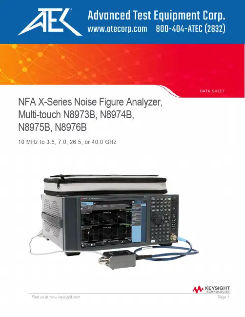
NFA X-Series Noise Figure Analyzer, Multi-touch N8973B, N8974B, N8975B, N8976B10 MHz to 3.6, 7.0, 26.5, or 40.0 GHzSpecificationsSpecifications describe the performance of parameters covered by the product warranty. These values are only valid for the stated operating frequency, and apply over 0°C to +55°C unless otherwise noted.95th percentile values indicate the breadth of the population (approx. 2 s) of perfor- mance tolerances expected to be met in 95 percent of the cases with a 95 percent confidence, for any ambient temperature in the range of +20°C to +30°C. In addition to the statistical observations of a sample of instruments, these values include the effects of the uncertainties of external calibration references. These values are not warranted. These values are updated occasionally if a significant change in the statistically observed behavior of production instruments is observed.Typical describes additional product performance information that is not covered by the product warranty. It is performance beyond specifications that 80 percent of the units exhibit with a 95 percent confidence level over the temperature range of +20°C to +30°C. Typical performance does not include measurement uncertainty.Nominal values indicate expected performance, or describe product performance that is useful in the application of the product, but are not covered by the product warranty.The analyzer will meet its specifications when:•It is within its calibration cycle•Under auto couple control, except when Auto Sweep Time Rules = Accy•Signals measured <10 MHz have DC coupling applied•The analyzer has been stored at an ambient temperature within the allowed operat- ing range for at least two hours before being turned on; if it had previously been stored at a temperature range inside the allowed storage range, but outside the allowed operating range•The analyzer has been turned on at least 30 minutes with Auto Align set to normal, or, if Auto Align is set to off or partial, alignments must have been run recently enough to prevent anAlert message; if the Alert condition is changed from Time and Temperature to one of thedisabled duration choices, the analyzer may fail to meet specifications without informing theuserFor the complete specifications guide, visit:/find/NFA_X-Series_specificationsFrequencyN8973B 10 MHz to 3.6 GHzN8974B 10 MHz to 7.0 GHzN8975B 10 MHz to 26.5 GHzN8976B410 MHz to 40.0 GHzN8973B, N8974B, N8975B, N8976B5 1 Hz to 3 MHz (in E24 series increments1), 4 MHz, 5 MHz, 6 MHz, 8 MHzAccuracy ± [RΔt + T + C]Aging rate ± 0.1 ppm2/year± 0.15 ppm/2 yearsTemperature stability +20°C to +30°CFull temperature range ± 0.015 ppm± 0.05 ppmR = aging rateΔt = time since last adjustmentT = temperature stabilityC = calibration accuracyAchievable initial calibration accuracy± 0.04 ppmExample frequency reference accuracy, Residual FM </= (use less than or equal to symbol)(0.25 Hz x N) p-p in 20 ms nominal1 year since last adjustment = ± (1 x 10⁻⁷ + 5 x 10⁻⁸ + 4 x 10⁻⁸) = ± 0 0.19 ppmFrequency readout accuracy (start, stop, center, marker) ± (marker frequency x frequency refe rence accuracy + 0.25% x span +5% x RBW + 2 Hz + 0.5 x horizontal resolution3)1. The E24 series is defined by international standard IEC 60063. E24 is a preferred series of numbers, with each number beingapproximately 10% larger than the previous number. It is commonly used for the labeling of 5% tolerance resistors, capacitors, etc.2. Parts per million (10-6)3. Horizontal resolution is span/(sweep points – 1).4. The N8976B ships with 346CK40. The 346CK40 has superior match above 26 GHz, which leads to better uncertainty.5. IQ analyzer (basic) mode has up to 25 MHz analysis BW.Note: The NFA X-Series noise figure analyzer is more than a dedicated noise figure analyzer. Eachmodel has full featured spectrum analyzer and IQ analyzer (basic) modes. The analyzer is specified to44 GHz when in SA or IQ analyzer modeNoise figure, gain, and uncertaintyExample DUT uncertainties1Without a PreampWith a USB Preamp2When combined with the U7227A/C/F preamp, the NFA X-Series noise figure analyzer offers improved uncertainty over the previous NFA-A in all of the above hypothetical cases.1. These uncertainties assume a measurement made with a N8975B at 1 GHz with a N4000A noise source and a non-frequency-converting DUT. The DUT is assumed to have an input/output match of 1.5 VSWR.2. Assuming a U7227A/C/F External USB Preamp is not warranted, does not include measurement uncertainty, and isvalid only at room temperature (approximately 23°C).Noise figure‹ 10 MHz10 MHz to internal preamplifier’s frequency limit1 Uncertainty calculator1See note1Internal and external preamplification recommended1Noise source ENR Measurement range Instrument uncertainty4 to 6.5 dB0 to 20 dB ± 0.02 dB12 to 17 dB0 to 30 dB ± 0.025 dB20 to 22 dB0 to 35 dB ± 0.03 dBGainInstrument uncertainty1DUT Gain range = –20 to +40 dB‹ 10 MHz See note110 MHz to 3.6 GHz ± 0.15 dB› 3.6 GHz ± 0.11 dB additional1 95th percentile, 5 minutes aftercalibratio nInstrument noise figureuncertaintySee the noise figure table abov eInstrument gain uncertainty See the gain table aboveInstrument noise figure See graphs of “Nominal instrument noise figure”; noisefigure is DANL + 176.24 dB (nominal)1. Note on DCcoupling1Instrument input match See graph: nominal VSWR. Note on DC coupling1Optional NFE improvement/internal Cal1See “Displayed average noise level (DANL) (with noisefloor extension) improvement” in the Option NFE -Noise floor extension chapter.1User calibration Best uncertainties; noise figure uncertainties calculator appliesUncalibrated Worst uncertainties; noise of the analyzer input acts as a second stage noise on the DUTInternal calibration Available with Option NFE. Good uncertainties without the need of reconnecting the DUT and running acalibration. The uncertainty of the analyzer input noise model adds a second-stage noise power to theDUT that can b e positive or negative. Running the noise figure uncertainty calculator will usually show thatinternal calibration achieves 90% of the possible improvement between the uncalibrated and usercalibration states.1. Refer to NFA X-Series specifications guide for footnote details2. Online uncertainty calculator at /find/nfuc or use the instrument’s built-in calculator.Nominal instrument noise figure, N8973B, N8974B, N8975BInternal Preamp noise figureFrequency Noise figure (nominal)100 kHz to 3.6 GHz 8 dB + (0.001112 * freq in MHz) nominal3.6 GHz to 8.4 GHz 9 dB nominal8.4 GHz to 13.6 GHz 10 dB nominal> 13.6 GHz DANL + 176.24 dB nominalMeasurement uncertainty is usually dominated by the uncertainty of the noise source, meaning that the instrument’s noise figure is negligible for most measurements. For situations when this noise figure becomes non-negligible (i.e. low-gain, low-noise DUTs), the included U7227 Series USB preamp provides extra measurement reliability.DANL (N8973B, N8974B, N8975B)1Frequency Specification Typical10.0 MHz to 2.1 GHz –161 dBm–163 dBm2.1 GHz to 7.0 GHz –160 dBm–162 dBm7.0 GHz to 13.6 GHz –160 dBm –163 dBm13.5 GHz to 17.1 GHz –157 dBm –160 dBm17.0 GHz to 20.0 GHz –155 dBm–159 dBm20.0 GHz to 26.5 GHz –150 dBm–156 dBmDANL (N8976B)110.0 MHz to 1.2 GHz –164 dBm–165 dBm1.2 GHz to2.1 GHz –163 dBm–164 dBm2.1 GHz to3.6 GHz –162 dBm –163 dBm3.5 GHz to 20.0 GHz –160 dBm –162 dBm20.0 GHz to 26.5 GHz –158 dBm–160 dBm26.4 GHz to 34.0 GHz –156 dBm–159 dBm33.9 GHz to 40.0 GHz –153 dBm –155 dBm Preamp noise figure and gain2Frequency 10 MHz to 4 GHz100 MHz to 26.5 GHz 2 GHz to 50 GHzNoise figure 10 MHz to 100 MHz: < 5.5 dB100 MHz to 4 GHz: < 5 dB 100 MHz to 4 GHz: < 6 dB 4 GHz to 6 GHz: < 5 dB6 GHz to 18 GHz: < 4 dB 18 GHz to 26.5 GHz: < 5 dBGain 10 to 100 MHz: > 16 dB100 MHz to 4 GHz: > 17 + 0.5F dB100 MHz to 26.5 GHz: > 16.1 + 0.26F dB 2 GHz to 50 GHz: > 16.5 + 0.23F dB Averaging Up to 10,000 measurement results* “F” signifies frequency in GHz1. Preamp on, input terminated, sample or average detector, log averaging, 0 dB input attenuation, IF Gain = High, +20°C to +30°C.2. See U7227A/C/F Data Sheet for list of specificationsRF inputN8973B, N8974B, N8975B Type-N female, 50 Ω nominalN8976B 2.4 mm male, 50 Ω nominalInput VSWR10 MHz to 3.6 GHz < 1.2:1 nominal 1.2:1 nominal3.6 GHz to 26.5 GHz < 1.9:1 nominal 1.5:1 nominal26.5 GHz to 44.0 GHz N/A < 1.8:1 nominalN8973B, N8974B, N8975B Type-N female, 50 Ω nominalN8976B 2.4 mm male, 50 Ω nominalLocal measurement and display update rate 11 ms (90/s)Remote measurement and LAN transfer rate 6 ms (167/s)Marker peak search 5 msCenter frequency tune and transfer (RF)22 msCenter frequency tune and transfer (µW)49 msMeasurement/mode switching 75 msAmplifier Includes any non-frequency-converting device (e.g. amplifiers, attenuators, filters, etc) Downconverting DUT With fixed or variable IF.Instrument capable of controlling an external LO via GPIB, LAN, or USBUpconverting DUT With fixed or variable IF.Ins trument capable o f controlling an external LO via GPIB, LAN, or USBSystem downconverter Allows the use of an external downconverting mixer as part of the measurement system.Instrument capable of controlling an external LO via GPIB, LAN, or USB MeasurementType4U multitouchOutput format Graphical, table of values, or meter modeDisplay channels 2Number of markers 4Limit lines Upper and lower for each of 2 channelsNoise figure Noise figure (F dB), or as a ratio (F)Gain Gain (G dB)Y-factor Y-factor (Y dB)T effective Effective noise temperature in KelvinP hot Relative power density in dBP cold Relative power density in dBFront panelProbe powerVoltage/current +15 Vdc ± 7 % at 150 mA max nominal-12.6 Vdc ± 10 % at 150 mA max nominal USB 2.0 portsMaster (2 ports) Standard Connector Output current Compatible with USB 2.0 USB Type-A female 0.5 A nominalMaster (1 port)High power Connector Output current Compatible with USB 2.0 USB Type-A Female 1.0A nominalRear panel connectivity10 MHz out Connector Output amplitude Frequency BNC female, 50 Ω nominal≥ 0 dBm nominal10 MHz ± (10 MHz x frequency reference accuracy)Ext ref in ConnectorInput amplitude range Input frequency Frequency lock range BNC female, 50 Ω nominal–5 to 10 dBm nominal10 MHz nominal± 5 x 10⁻⁶ of specified external reference input frequencyTrigger 1 and 2 inputs Connector Impedance Trigger level range BNC female> 10 kΩ n ominal –5 to 5 VTrigger 1 and 2 inputs Connector Impedance Trigger level range BNC female50 Ω nominal 5 V TTL nominalMonitor output Connector Format Resolution BVGA compatible, 15-pin mini D-SUBXGA (60 Hz vertical sync rates, non-interlaced) analog RGB 1024 x 768Noise source drive +28 V (pulsed)Connector BNC femaleSNS Series noise source connector For use with Keysight SNS Series noise sources USB 2.0 portsMaster (3 ports) Standard Connector Oupt current Compatible with USB 2.0 USB Type-A female 0.5 A nominalSlave (1 port) Standard Connector Output current Compatible with USB 2.0 USB Type-B female 0.5 A nominalGPIB interface Connector GPIB codes GPIB mode IEEE-488 bus connectorSH1, AH1, T6, SR1, LR1, PP0, DC1, C1, C2, C3, C28,DT1, L4, C0 Controller or deviceLAN TCP/IP interface Standard Connector 1000 Base-T RJ45 EthertwistGeneral SpecificationsOperating 0 to 55°CStorage –40 to 70°CComplies with the essential requirements of the European EMC Directive as well as current editions of the following standards (dates and editions are cited in the Declaration of Conformity):•IEC/EN 61326-1 or IEC/EN 61326-2-1•CISPR 11 Group 1, Class A•AS/NZS CISPR 11:2002•ICES/NMB-001This ISM device cmplies with Canadian ICES-001Get appareil ISM est conforme à la norme NMB-001 du CanadaComplies with European Low Voltage Directive 2006/95/EC•IEC/EN 61010-1 3rd Edition•Canada: CSA C22.2 No. 61010-1-12•U.S.A.: UL 61010-1 3rd EditionAcoustic noise emissionLpA < 70 dBOperator positionNormal positionPer ISO 7779Samples of this product have been type tested in accordance with the Keysight Environmental Test Manual and verified to be robust against the environ- mental stresses of storage, transportation, and end-use; those stresses include, but are not limited to, temperature, humidity, shock, vibration, altitude, and power line conditions; test method are aligned with IEC 60068-2 and levels are similar to MILPRF-28800F Class 3.Voltage and frequency 100 to 120 V, 50/60/400 Hz220 to 240 V, 50/60 HzPower consumptionOn Standby 350 W maximum 20 WResolution 1280 × 768, WXGASize 269 mm (10.6 in.) diagonal (nominal)Find us at Page 11Find us at Page 12 This information is subject to change without notice. © Keysight Technologies, 2016-2018, 2020, Published in USA, November 24, 2020, 5992-1270EN Learn more at: For more information on Keysight Technologies’ products, applications or services,please contact your local Keysight office. The complete list is available at:/find/contactusGeneral Specifications (continued) Data storageInternal External ≥ 160 GB nominal (removable solid -state drive) Supports USB 2.0 compatible memory devicesInternal External≥ 160 GB nominal (removable solid -state drive) Supports USB 2.0 compatible memory devices Weight (without options)Net18 kg (40 Ibs) nominal Shipping 30 kg (66 Ibs) nominalDimensionsHeight177 mm (7.0 in) Width426 mm (16.8 in) Length 368 mm (14.5 in)WarrantyThe NFA noise figure analyzer is supplied with a standard 1-year warrantyCalibration cycleThe recommended calibration cycle is two years: calibration services are available through Keysight service centers。
是德科技噪声系数选型指南将噪声系数不确定度降至最低选型指南灵活的解决方案组合满足广泛需求目录将噪声系数不确定度降至最低 (2)噪声系数概述 (3)测量不确定度 (4)噪声系数测量系统的组成 (5)噪声系数分析仪 (10)X 系列信号分析仪(PXA/MXA/EXA/CXA) (11)PNA-X 微波网络分析仪 (13)SNS 系列智能噪声源 (14)346 系列传统噪声源 (15)噪声源测试仪 (17)其他资源 (18)将噪声系数不确定度降至最低噪声系数是表征接收机的关键参数之一,此外还可以表征接收机在自身所生成的噪声干扰下探测微弱输入信号的能力。
想要降低噪声系数,首先要全面地了解元器件、子系统和测试装置的不确定度。
这些未知因素的量化分析,必须依赖能够提供精确、可靠结果的灵活型工具。
是德科技噪声系数解决方案组合包含丰富的仪器、应用软件和附件,可帮助您优化测试装置并识别多余的噪声源。
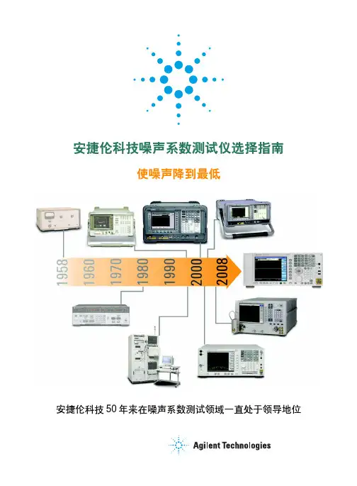
我们提供噪声系数测试解决方案已有 50 多年的历史,从最初只是提供基础型噪声计,发展到目前能够提供基于频谱分析仪、网络分析仪和噪声系数分析仪的现代化解决方案。
本选型指南的第 3 页到第 9 页简要介绍了噪声系数的基本知识。
第 10 页到第 19 页展示了我们当前的产品线,并将帮助您找到更适合自身应用的解决方案,无论您的目标是设计出性能合格、良好还是优秀的器件。
相关资源参见第 20 页。
我们发布了一个系列七篇应用指南,它们将能够帮助您更深入地了解噪声系数及其固有挑战。
如欲了解更多信息,请访问/find/noisefigure噪声系数概述噪声系数作为接收机表征的关键参数之一,主要表征接收机及其更低级别组成元件在有热噪声存在的情况下处理微弱信号的能力。
例如,在测量低噪声放大器(LNA)时,噪声系数描述的是由于 LNA 中的有源器件在内部产生噪声而导致的信噪比下降。
噪声的精确测量对于产品的设计和开发都非常关键。
高度精确的测量可以保证仿真结果与真实测量结果之间有更高的一致性,并有助于发现在仿真过程中没有考虑到的噪声来源。
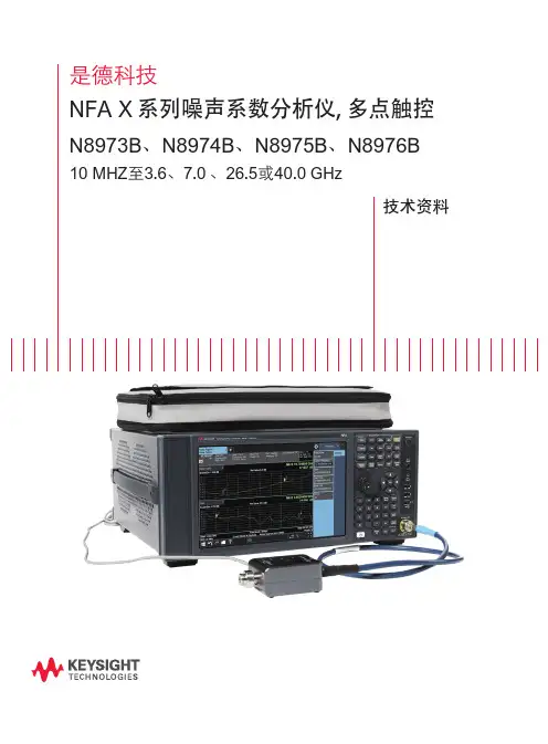
是德科技NFA X系列噪声系数分析仪, 多点触控N8973B、N8974B、N8975B、N8976B 10 MHZ至3.6、7.0、26.5或40.0 GHzरຍጨଙ技术指标技术指标描述产品保证的参数性能。
除非另有说明,这些值仅在所述的工作频率下有效,适用于 0℃至 +55℃的温度范围。
95% 表示环境温度在 +20 至 +30°C 之间时,在 95% 的情况下有 95% 的把握预计能够达到性能容限范围(≈ 2 σ)。
除了仪器样品的统计观测数据之外,这些值还包括外部校准参考的不确定度影响。
但是不保证所有仪器都能达到这些值。
如果生产仪器的统计观测特性出现重大变化,这些值可能不定期更新。
典型值是指不在产品保证范围之内的其他产品性能信息,指的是在 +20℃至 +30℃的温度范围内80%的设备可以表现出 95% 的置信度的性能指标。
典型性能不包括测量不确定度。
标称值是指预计的性能,或描述在产品应用中有用但未包含在产品保证范围内的产品性能。
在下列条件下,分析仪能够达到其技术指标:–分析仪处于校准期内–除 Auto Sweep Time Rules(自动扫描时间规则)=Accy(精确)外,分析仪处于自动耦合控制下–测得信号 <10 MHz,应用直流耦合–如果分析仪是在允许的储存温度范围内但超出允许的工作温度范围的环境中存放,则在启动分析仪之前,必须将其放在允许的工作温度范围内至少两小时。
–如果 Auto Align(自动校正)设置为 normal(正常),则分析仪必须开机至少 30 分钟;如果 Auto Align 设置为 off(关闭)或 partial(部分),则必须在近期进行过校正,以避免出现告警消息;一旦告警条件从 Time and Temperature(时间和温度)变成禁用的时间长度之一,则该分析仪可能达不到相关技术指标,并且不会通知用户。
请访问以下网站,获取完整的技术指标指南:/find/NFA_X-Series_specifications频率频率范围N8973B 10 MHz 至 3.6 GHz N8974B 10 MHz 至 7.0 GHz N8975B 10 MHz 至 26.5 GHz N8976B 410 MHz 至 40.0 GHz测量带宽(标称值)N8973B 、N8974B 、N8975B 、N8976B 5 1 Hz 至 3 MHz (E24 系列增量1),4 MHz ,5 MHz ,6 MHz ,8 MHz 频率参考精度± [R Δt + T + C]R = 老化率Δt = 离上次调整的时间T = 温度稳定性C = 校准精度老化率± 0.1 ppm 2/年± 0.15 ppm/2 年温度稳定性+20°C 至 +30°C 完整温度范围± 0.015 ppm ± 0.05 ppm 可实现的初始校准精度± 0.04 ppm采样频率参考精度,剩余 FM </= (使用小于或等于符码)(0.25 Hz x N )p-p ,20 ms 内的标称值自上次校准 1 年后= ± (1 x 10⁻⁷ + 5 x 10⁻⁸ + 4 x 10⁻⁸)= ± 0 0.19 ppm频率读数精度(起始、终止、中心、游标)±(游标频率 x 频率参考精度 + 0.25% x 扫宽 + 5% x RBW + 2 Hz + 0.5 x 水平分辨率3)1. E 24 系列依照国际标准 IEC 60063 来定义。
射频噪声系数分析仪AV3984A射频噪声系数分析仪是针对射频段噪声系数的测试需求开发的一款具有较高性价比测量仪器。
整机采用嵌入式PC兼容的硬件平台、Windows 2000操作系统软件平台、低噪声前置放大器、全数字中频处理等技术,配合固态噪声源,可实现10MHz〜3GHz频率范围内噪声系数单边带、高精度、快速扫频测量。
是射频段线性和准线性二端口网络或系统噪声系数测量的理想设备。
具有噪声系数、增益、Y因子、等效噪声温度和冷、热功率等多种参数的测量功能,并提供测量模式设置向导功能,可方便用户使用,适合于实验室,生产线等多种测量现场!主要特点:•用户界面灵活而直观•全彩LCD双通道显示噪声系数及相关参数和增益随频率的变换曲线•具备六种分辨率带宽供用户选择•完善的测量功能,能实现对放大器、上下变频器类的器件或系统的噪声系数和增益测量•具有损耗补偿功能。
能以固定、表格或组合的形式补偿被测件前后的损耗,用于解决需要去嵌的射频管芯的测试难题•外设接口丰富,复用性强•具有双噪声源驱动能力,支持普通噪声和智能噪声源。
智能噪声源即插即用,超噪比白动加载■用户界面灵活直观用户界面直观便于使用,所有按键按功能分类排放,一目了然,易于查找。
专用功能键的层数简单,母菜单子菜单分层明确,屏幕上实时显示仪器测试状态,使测量更具准确性,及时的测量提示和向导对话框使测量更加准确快速!•全彩LCD高清显示AV3984A毫米波噪声系数分析仪配备17cm的全彩色LCD显示器,同时显示噪声系数和增益随频率的变化,大大提高了使用的舒适度和清晰度。
同时具备多种显示效果:三种显示格式、两个独立通道、多种组合曲线图形,多达六类的测量结果等等。
•可变测量带宽对于现代的许多应用,4MHz带宽在噪声测试系统中仍然适用。
然而,无线通信的迅猛发展和射频频谱的日益拥塞逐渐对窄带噪声系数测量提出了需求。
AV3984A毫米波噪声系数分析仪采用可变测量带宽,可以实现4MHz , 2MHz , 1MHz , 400kHz , 200kHz 和100kHz不同分辨率带宽下的实际测量,这点对于提高窄带测量精确度尤为重要! •完善的损耗补偿损耗补偿功能,能以固定、表格或组合的形式补偿补偿被测件前后通道中的损耗。
噪声系数测量的三种方法摘要:本文介绍了测量噪声系数的三种方法:增益法、Y系数法和噪声系数测试仪法。
这三种方法的比较以表格的形式给出。
在无线通信系统中,噪声系数(NF)或者相对应的噪声因数(F)定义了噪声性能和对接收机灵敏度的贡献。
本篇应用笔记详细阐述这个重要的参数及其不同的测量方法。
噪声指数和噪声系数噪声系数(NF)有时也指噪声因数(F)。
两者简单的关系为:NF= 10* log10 (F)定义噪声系数(噪声因数)包含了射频系统噪声性能的重要信息,标准的定义为:从这个定义可以推导出很多常用的噪声系数(噪声因数)公式。
下表为典型的射频系统噪声系数:Cate goryMAXIM Prod uctsNoise Figu re* A pplic ation s Ope ratin g Fre quenc y Sys tem G ainL NA MA X26400.9d B Cel lular, ISM400M Hz ~1500M Hz 15.1dBLNA M AX2645 HG: 2.3d B WLL 3.4G Hz ~3.8GH z HG: 14.4dB LG: 15.5dB WLL 3.4GH z ~ 3.8GHz LG:-9.7d BMix er MA X268413.6dB LM DS, W LL 3.4GHz~ 3.8GHz 1dBMi xer M AX9982 12d B Cel lular, GSM825M Hz ~915MH z 2.0dBRe ceive r Sys tem M AX2700 3.5dB ~19dBPCS,WLL 1.8GHz ~ 2.5GHz< 80d B*HG =高增益模式,LG =低增益模式噪声系数的测量方法随应用的不同而不同。
噪音分析仪噪音分析仪是一种用于测量和分析环境中噪音水平的仪器。
它通过测量声波的振动幅度和频率来确定噪音的强度和特征。
噪音分析仪通常由声音传感器、信号处理单元和显示屏组成,可以提供准确的数据和音频图形,以帮助用户识别并解决噪音问题。
本文将介绍噪音分析仪的原理、应用领域和优势。
噪音分析仪能够测量环境中的各种噪音源,包括交通噪声、工业噪声、建筑施工噪声等。
通过收集并分析噪音数据,我们可以评估噪音对人们的健康和生活质量的影响,并采取相应的措施来减少噪音污染。
噪音分析仪还可用于工厂、办公室和住宅等各种场所的噪音监测,以确保环境符合相关的噪音标准和规定。
噪音分析仪的工作原理是基于声学原理。
当声波进入仪器时,传感器会将声音转换为电信号,并传输给信号处理单元进行处理。
信号处理单元会对电信号进行放大、滤波和频谱分析等操作,以得到噪音的强度和频率分布情况。
最后,结果会显示在仪器的显示屏上,供用户进行观察和分析。
噪音分析仪在许多领域有广泛的应用。
首先,它在环境保护方面起到了至关重要的作用。
通过测量和分析噪音水平,我们可以评估环境是否符合噪音标准,并及时采取措施,以减少噪音对人们的影响。
其次,噪音分析仪在工程领域也被广泛使用。
例如,在建筑施工过程中,我们可以使用噪音分析仪来监测施工噪声,以确保其不会对周围的居民和环境造成不必要的干扰。
此外,噪音分析仪还可用于汽车工业、航空工业、电力工业等领域,以帮助解决噪音问题和改进产品设计。
噪音分析仪相比传统的噪音测量方法具有许多优势。
首先,它能够提供更准确的测量结果。
传统的噪音测量方法通常使用人工记录或简单的噪音计量仪器,这种方法往往存在主观性和不准确性的问题。
而噪音分析仪可以提供更高精度的数据,从而更准确地评估噪音水平。
其次,噪音分析仪具有更强大的功能。
传统的噪音测量方法只能提供噪音的整体水平,而噪音分析仪可以提供更多的信息,如噪音频率分布和时域图形等。
这些信息对于识别噪音源和分析噪音特征非常重要。
AgilentN8972A, N8973A, N8974A, N8975A NFA Series Noise Figure AnalyzersConfiguration GuideThis configuration guide will assist withoptimization of an NFA series noise figureanalyzer for specific applications.Models• N8972A noise figure analyzer (10 MHz to 1.5 GHz)• N8973A noise figure analyzer (10 MHz to 3.0 GHz)• N8974A noise figure analyzer (10 MHz to 6.7 GHz)• N8975A noise figure analyzer (10 MHz to 26.5 GHz) 1981NFA series noise figure analyzersN8972A 10 MHz to 1.5 GHz NFA series noise figure analyzerN8973A 10 MHz to 3.0 GHz NFA series noise figure analyzerN8974A 10 MHz to 6.7 GHz NFA series noise figure analyzerN8975A 10 MHz to 26.5 GHz NFA series noise figure analyzerStandard NFA seriesnoise figure analyzers include:• A flexible and intuitive user interface•Easy measurement setup•Low instrument uncertainty•Color graphical display of noise figure and gain versus frequency•Enhanced PC and printer connectivity•SNS series noise source compatible•Ability to automatically upload ENR calibrationdata from SNS series noise sources•Local oscillator control through second dedicated GPIB•3-year warranty as standardUpgrading a modelAll options other than those marked with *, can be ordered at any time for use with an instrument.Noise sources(required to make noise figure measurements)The Agilent SNS Series of noise sources are recommended for use with the Agilent NFA. These noise sources work in conjunction with the NFA Series analyzers to simplify measurement set-up and improve accuracy.Frequency range:N4000A nominal ENR 6dB 10MHz to 18GHzN4001A nominal ENR 15dB 10MHz to 18GHzN4002A nominal ENR 15dB 10MHz to 26.5GHzThe new SNS Series of noise sources are designed specifically for use with the NFA Series of noise figure analyzers. The new noise sources cover the majority of applications with a range of frequencies, ENR and also coaxial connector types.Unique calibration data is stored electronically inside the SNS and is automatically downloaded when connectedto the Agilent noise figure analyzer. The SNS Series also has the capability to measure it’s own temperature so that compensation can be applied to it’s calibration. These features will lead to more reliable measurements.Other compatible noise sources include the Agilent 346 (co-axial) series and the 347 (waveguide) series. Compatible local oscillatorsThe NFA Series noise figure analyzers support the use ofa local oscillator as part of your measurement setup, if you are making measurements on frequency translating devices or making measurements our of one standard frequency range of your noise figure analyzer. SCPI compatible signal generators are recommended, but users may also use their own custom command set.Please note: Care must be taken when specifying a local oscillator, as factors such as phase noise, spectral purity and noise floor of the signal generator may affect noise figure measurements. Filtering may therefore be required on some models of signal generators to enable accurate noise figure measurements to be made. Compatible printersA supported printer is defined as one that is equipped with a parallel interface and accepts printer control language (PCL) level 3 or 5. Purchase an IEEE 1284 compliant printer cable to enable the printer to be used.For further informationAgilent NFA Series – noise figure analyzer applicationand product information is listed below.Key literaturePlease visit the Agilent noise figure analysis web site for on-line access to literature or contact your local Agilent sales office or representative.NFA Series - Noise Figure Analyzers, Brochure,literature number 5980-0166ENFA Series - Noise Figure Analyzers,Technical Specifications, literature number 5980-0164E NFA Series – Noise Figure AnalyzerProgramming Examples,literature number 5968-9498E Fundamental of RF and Microwave Noise Figure Measurements, Application Note 57-1,literature number 5952-8255ENoise Figure Measurement Accuracy ApplicationNote 57–2, literature number 5968-4545E10 Hints for Making Successful Noise Figure Measurements, Application Note 57-3,literature number 5980-0288ESNS Series – Noise Sources, Product Overview,literature number 5988-0081ENKey web resourcesFor the latest information on our noise figure solutions, visit our web page at:/find/nfFor the latest news on the component test industry,visit our web page at:/find/component_testFor on-line manuals, visit our web page at:/find/manualsFundamentals of Noise Figure Measurements Net Seminar (archived version)3Agilent Technologies’ Test and Measurement Support, Services, and AssistanceAgilent Technologies aims to maximize the value you receive, while mini-mizing your risk and problems. We strive to ensure that you get the test and measurement capabilities you paid for and obtain the support you need. Our extensive support resources and services can help you choose the right Agilent products for your applications and apply them success-fully. Every instrument and system we sell has a global warranty. Support is available for at least five years beyond the production life of the prod-uct. Two concepts underlie Agilent’s overall support policy: “Our promise” and “Your Advantage.”Our PromiseOur Promise means your Agilent test and measurement equipment will meet its advertised performance and functionality. When you are choos-ing new equipment, we will help you with product information, including realistic performance specifications and practical recommendations from experienced test engineers. When you use Agilent equipment, we can verify that it works properly, help with product operation, and provide basic measurement assistance for the use of specified capabilities, at no extra cost upon request. Many self-help tools are available.Your AdvantageYour Advantage means that Agilent offers a wide range of additional expert test and measurement services, which you can purchase accord-ing to your unique technical and business needs. Solve problems effi-ciently and gain a competitive edge by contracting with us for calibration,extra-cost upgrades, out-of-warranty repairs, and on-site education and training, as well as design, system integration, project management, and other professional engineering services. Experienced Agilent engineers and technicians worldwide can help you maximize your productivity, opti-mize the return on investment of your Agilent instruments and systems,and obtain dependable measurement accuracy for the life of those products.Get the latest information on the products and applications you select.By internet, phone, or fax, get assistance with all your test & measurement needsOnline assistance:/find/assistPhone or Fax Product specifications and descriptions in this document subject to change without notice.© Agilent Technologies, Inc. 2002Printed in USA, June 5, 20025980-0163EUnited States:(tel) 800 452 4844Canada:(tel) 877 894 4414(fax) 905 282 6495China:(tel) 800 810 0189(fax) 800 820 2816Europe:(tel) (31 20) 547 2323(fax) (31 20) 547 2390Japan:(tel) (81) 426 56 7832(fax) (81) 426 56 7840Korea:(tel) (82 2) 2004 5004 (fax) (82 2) 2004 5115Latin America:(tel) (305) 269 7500(fax) (305) 269 7599Taiwan:(tel) 0800 047 866 (fax) 0800 286 331Other Asia Pacific Countries:(tel) (65) 6375 8100 (fax) (65) 6836 0252Email:*******************/find/emailupdatesGet the latest information on the products and applications you select.Agilent Email Updates。
噪声系数分析仪安全操作及保养规程噪声系数分析仪是一种用于测量设备或系统中噪声水平的仪器,具有测量准确、操作简便、范围广泛等特点,广泛应用于电子、通信、航空航天、环境检测等领域。
为了保障仪器的正常使用和工作效率,必须严格遵守安全操作规程和保养流程。
本文将从噪声系数分析仪的安全操作和保养两个方面展开介绍。
噪声系数分析仪的安全操作规程1. 使用前的准备工作在进行仪器的使用之前,需要完成以下的准备工作:•安装:将噪声系数分析仪放在平稳的地面上,由专业人员完成固定和接线的操作。
•检查:仪器的外观是否完好无损,内部连接是否稳固,仪器指示灯是否正常发亮。
•校准:根据实验要求进行校准操作,确保仪器的准确性和可靠性。
2. 使用过程中的安全操作在仪器使用过程中,需要注意以下的安全操作规程:•启动:按照操作说明书的要求进行启动操作,不得随意更改任何设置。
•操作:操作时应轻柔并注意力度,严禁拆卸或更换任何部件。
•包装:使用完毕后应拔掉电源,仪器应存放在干燥、通风、无尘的地方,并用机箱密封。
•处理:当出现任何异常或故障时,应立即停止使用仪器,并联系专业人员处理。
3. 维护保养噪声系数分析仪保养工作应遵循以下规程:•日常检查:每日开机、关闭及使用前应检查仪器的操作情况、仪器的工作状态是否正常及检查是否有毛刺等损伤的情况。
•保养清洁:应定期对仪器进行清洁,清理仪器所在场地及所有易受污染的部件。
•手续更新:对所有维修、检查和保养情况,应填写相应的保养记录和检查报告。
噪声系数分析仪的保养流程1. 日常清洁定期进行清洁工作,避免灰尘、油污等外部影响对仪器的影响。
•清洁仪器表面:用干净软布或棉拭轻轻擦拭仪器外表面,杜绝水或其它液体进入仪器内部,也可以使用清洁水进行清洗;•清洁仪器内部:根据仪器的使用情况,定期进行内部清洁洁和排污,避免影响仪器的精度和准确性。
2. 定期校准根据实验要求定期对噪声系数分析仪进行校准,保证仪器的稳定性和准确性。
是德科技噪声系数选型指南将噪声系数不确定度降至最低选型指南灵活的解决方案组合满足广泛需求目录将噪声系数不确定度降至最低 (2)噪声系数概述 (3)测量不确定度 (4)噪声系数测量系统的组成 (5)噪声系数分析仪 (10)X 系列信号分析仪(PXA/MXA/EXA/CXA) (11)PNA-X 微波网络分析仪 (13)SNS 系列智能噪声源 (14)346 系列传统噪声源 (15)噪声源测试仪 (17)其他资源 (18)将噪声系数不确定度降至最低噪声系数是表征接收机的关键参数之一,此外还可以表征接收机在自身所生成的噪声干扰下探测微弱输入信号的能力。
想要降低噪声系数,首先要全面地了解元器件、子系统和测试装置的不确定度。
这些未知因素的量化分析,必须依赖能够提供精确、可靠结果的灵活型工具。
是德科技噪声系数解决方案组合包含丰富的仪器、应用软件和附件,可帮助您优化测试装置并识别多余的噪声源。
我们提供噪声系数测试解决方案已有 50 多年的历史,从最初只是提供基础型噪声计,发展到目前能够提供基于频谱分析仪、网络分析仪和噪声系数分析仪的现代化解决方案。
本选型指南的第 3 页到第 9 页简要介绍了噪声系数的基本知识。
第 10 页到第 19 页展示了我们当前的产品线,并将帮助您找到更适合自身应用的解决方案,无论您的目标是设计出性能合格、良好还是优秀的器件。
相关资源参见第 20 页。
我们发布了一个系列七篇应用指南,它们将能够帮助您更深入地了解噪声系数及其固有挑战。
如欲了解更多信息,请访问/find/noisefigure噪声系数概述噪声系数作为接收机表征的关键参数之一,主要表征接收机及其更低级别组成元件在有热噪声存在的情况下处理微弱信号的能力。
例如,在测量低噪声放大器(LNA)时,噪声系数描述的是由于 LNA 中的有源器件在内部产生噪声而导致的信噪比下降。
噪声的精确测量对于产品的设计和开发都非常关键。
高度精确的测量可以保证仿真结果与真实测量结果之间有更高的一致性,并有助于发现在仿真过程中没有考虑到的噪声来源。
Noise Figure AnalyzersN8972A N8973A N8974A N8975ANFA SeriesA Flexible and Intuitive User InterfaceThe user interface on the new NFA series of Noise Figure Analyzers is intuitive and easy to use, with easy to find keys, which are sized and then placed in the relevant key group according to function. The soft-key depths have been kept to a minimum and there are clear visual indicators on the screen showing the current machine state.Easy Measurement SetupThe NFA series of Noise Figure Analyzers now takes the pain out of complex measurement setups, with their simple but instructive menus. The built-in help button gives key function and remote pro-gramming commands, that should eliminate the need to carry man-uals when setting up measurements.Low Instrumentation UncertaintyWhen making noise figure measurements, a key parameter to be aware of is measurement uncertainty. The NFA has a low instru-mentation uncertainty to aid in accurate and repeatable measure-ment of manufacturers’ components. In addition, to aid customers in setting their components/systems specifications, Agilent has pro-duced a web-based uncertainty calculator that will give customers information on how to improve and classify their measurement specifications more accurately.For more information, visit our web site at: /find/nfIncrease Measurement ThroughputIn manufacturing environments, fast measurement speed and repeatability are critical. The NFA series of Noise Figure Analyzers now include many features that can reduce your measurement time and increase throughput. The frequency list function allows you to select specific points within a complete measurement span to make your measurement. The Sweep averaging function allows a real-time update to the screen during a measurement, as you adjust the per-formance of the DUT during a sweep. Both these functions, as well as the limit line functionality for quick and easy pass/fail testing and the additional ability to recall complete calibrated instrument states, increase productivity and measurement throughput.Enhanced ConnectivityThe built-in floppy disk drive, GPIB, RS232 serial and Printer port connectors allow quick and easy data transfer between the analyzer and a PC or workstation. There is also a built-in VGA connector for connecting a large-screen monitor.Color Graphical DisplayTo enhance usability, the new Noise Figure Analyzers now come with an integrated 17 cm full color LCD display, for simultaneous viewing of noise figure and gain against frequency. There are three different formats for viewing measurements, the two separate chan-nel or combined graph format, a table format, and a spot frequency noise figure and gain measurement “meter” format.Ease of AutomationThe NFA series of Noise Figure Analyzers include 2 industry-stan-dard GPIB ports and an RS232 serial port, to aid in the automated control of the instrument. The second GPIB port is dedicated to Local oscillator control. The default control language is SCPI, but users can also define custom LO commands.Ease of IntegrationTo aid with the integration of the new analyzer into manufacturing environments, Agilent has produced a Programmers Reference Manual containing example programs to help migrate to the new system. The NFA is not code compatible with the 8970B, nor can it control the 8971C.Full Measurement CapabilityFeatures present in all NFA series noise figure analyzers•ENR data automatically loaded into NFA series noise figure analyzer when using SNS noise source•Floppy disk loading and saving of ENR data when used with a 346 or 347 noise source•Enhanced analysis through Limit lines and Marker functions •Enhanced PC and printer connectivity and VGA output•Internal data storage capable of storing up to 30 different state,trace, and setup files (dependent upon measurement complexity)•4 MHz measurement bandwidth•Frequency list mode, which enables the user to avoid known, polluted frequencies during a measurement or, used tactically to speed up a measurementFeatures only Available on the N8973A, N8974A, N8975A•Lower noise figure measurement uncertainty ±<0.05 dB•Six user selectable bandwidths (100 KHz, 200 KHz, 400 KHz, 1 MHz, 2 MHz, and 4 MHz)• Enhanced speed•A flexible and intuitive user interface •Easy measurement setup •Low instrument uncertainty•Color graphical display of noise figure and gain versus frequency •Enhanced PC and printer connectivity•SNS, 346 and 347 Series noise source compatible•Ability to automatically upload ENR calibration data from SNS Series noise source•Local oscillator control through second dedicated GP-IB •3-year warranty as standardN8973ANoise Figure AnalyzersN8972A N8973A N8974A N8975A NFA Series Key SpecificationsSpecifications apply over 0°C to +55°C unless otherwise noted. Theanalyzer will meet its specifications after 2 hours of storage withinthe operating temperature range, 60 minutes after the analyzer isturned on, with Alignment running. A user calibration is requiredbefore corrected measurements can be made.Frequency RangeNFA Series:N8972A10 MHz to 1.5 GHzN8973A10 MHz to 3 GHzN8974A10 MHz to 6.7 GHzN8975A10 MHz to 26.5 GHzMeasurement Speed (nominal)8 Averages 64 AveragesN8972A:<100 ms/measurement<80 ms/measurementN8973A:<50 ms/measurement<42 ms/measurementN8974A:<70 ms/measurement<50 ms/measurementN8975A:<70 ms/measurement <50 ms/measurementMeasurement Bandwidth (nominal)N8972A:4 MHzN8973A, N8974A, N8975A:4 MHz, 2 MHz, 1 MHz, 400 kHz, 200 kHz, 100 kHzNoise Figure and Gain(Performance is dependent upon ENR of noise source used)N8972A Noise Source ENR4 – 7 dB12 – 17 dB20 – 22 dBNoise FigureMeasurement range0 to 20 dB0 to 30 dB0 to 35 dBInstrument uncertainty±<0.1 dB±<0.1 dB±<0.15 dBGainMeasurement range–20 to +40 dBInstrument uncertainty±<0.17 dBN8973A, N8974A and Noise Source ENRN8975A(10 MHz to 3.0 GHz) 4 – 7 dB12 – 17 dB20 – 22 dBNoise FigureMeasurement range0 to 20 dB0 to 30 dB0 to 35 dBInstrument uncertainty±<0.05 dB±<0.05 dB±<0.1 dBGainMeasurement range –20 to +40 dBInstrument uncertainty±<0.17 dBN8974A and N8975A Noise Source ENR(>3.0 GHz) 4 – 7 dB12 – 17 dB20 – 22 dBNoise FigureMeasurement range0 to 20 dB0 to 30 dB0 to 35 dBInstrument uncertainty±<0.15 dB±<0.15 dB±<0.2 dBGainMeasurement range–20 to +40 dBInstrument uncertainty±<0.17 dBCharacteristic1Noise figure at 23ºC ±3ºC (10 MHz to 3.0 GHz)Characteristic1Noise figure at 23ºC ±3ºC (3.0 GHz to 26.5 GHz)Characteristic values are met or bettered by 90% of instruments with 90%confidence.Frequency ReferenceStandard Opt.1D5Aging±<2 ppm1/year±<0.1 ppm/yearTemperature stability±<6 ppm±<0.01 ppmSettability ±<0.5 ppm±<0.01 ppmTuning Accuracy (Start, Stop, Center, Marker)4 MHz Measurement Bandwidth (default on all models of Noise FigureAnalyzer)Frequency Error10 MHz – 3.0 GHz±<Reference error + 100 kHz3.0 GHz – 26.5 GHz±<Reference error + 400 kHz<4MHz Measurement Bandwidth (functionality not present in N8972A)Frequency Error10 MHz – 3.0 GHz±<Reference error + 20 kHz3.0 GHz – 26.5 GHz±<Reference error + 20% of measurementbandwidthParts Per Million (10e-6)1086421050010001500200025003000Frequency (MHz)NoiseFigure(dB)8911112Frequency (MHz)NoiseFigure(dB)3388347756517418833818791871721956118112724136814492153761626171451829189131879716812156522419233342421251225986265Noise Figure AnalyzersN8972A N8973A N8974A N8975AGeneral SpecificationsDimensionsWithout handle: 222 mm H x 375 mm W x 410 mm D With handle (max): 222 mm H x 409 mm W x 515 mm D Weight (typical, without options)N8972A:15.3 kg N8973A:15.5 kg N8974A:17.5 kg N8975A:17.5 kgData Storage (nominal)Internal drive: 30 traces, states or ENR tables Floppy disk: 30 traces, states or ENR tablesPower RequirementsOn (line 1): 90 to 132 V rms, 47 to 440 Hz, 195 to 250 V rms, 47 to 66 Hz Power consumption: <300 W Standby (line 0): <5 W Temperature RangeOperating: 0ºC to +55ºC Storage: –40ºC to +70ºCHumidity RangeOperating: Up to 95% relative humidity to 40ºC (non-condensing)Altitude range: Operating to 4,600 meters Calibration Interval1-year minimum recommendedElectromagnetic CompatibilityComplies with the requirements of the EMC directive 89/336/EEC. This includes Generic Immunity Standard EN 50082-1:1992 and Radiated Interference Standard CISPR 11:1990/EN 55011:1991, Group 1 Class A.The conducted and radiated emissions performance typically meets CISPR 11:1990/EN 55011:1991 Group 1 Class B limits.Warranty3-Year warranty as standardKey LiteratureNoise Figure Analyzers, NFA Series, Brochure, p/n 5980-0166ENoise Figure Analyzers, NFA Series, Data Sheet, p/n 5980-0164ENoise Figure Analyzers, NFA Series, Configuration Guide, p/n 5980-0163EFundamentals of RF and Microwave Noise Figure Measurements, App note 57-1, p/n 5952-8255E Noise Figure Measurement Accuracy, App note 57-2, p/n 5952-370610 Hints for Making Successful Noise Figure Measurements, p/n 5980-0228E N8972A and N8973A, NFA Series, Noise Figure Analyzer ProgrammingExamples, p/n 5968-9498EOrdering InformationN8972A 10 MHz to 1.5 GHz NFA Series Noise Figure Analyzer N8973A 10 MHz to 3.0 GHz NFA Series Noise Figure Analyzer N8974A 10 MHz to 6.7 GHz NFA Series Noise Figure Analyzer N8975A 10 MHz to 26.5 GHz NFA Series Noise Figure AnalyzerAll options, other than those marked with *, can be ordered at any time for use with an instrument.Frequency ReferenceN897xA-1D5NFA series high stability frequency reference*Calibration DocumentationN897xA-A6J NFA series ANSI Z540 compliant calibration with test data*AccessoriesN897xA-1CP NFA series rackmount and handle kit N897xA-UK9NFA series front panel coverN897xA-1FP NFA series calibration, performance verification and adjustment softwareDocumentationA hard copy and CD version of the English language Quick Reference Guide, User’s Guide, Programmers Reference, and Calibration andPerformance Verification Manual are included with the NFA as standard.Selections can be made to change the localization of the manual set or to delete the hardcopy.N897xA-AB0NFA series manual set for Taiwan – Chinese localization N897xA-AB1NFA series manual set – Korean localization N897xA-AB2NFA series manual set – Chinese localization N897xA-ABE NFA series manual set – Spanish localization N897xA-ABF NFA series manual set – French localization N897xA-ABZ NFA series manual set – Italian localization N897xA-ABD NFA series manual set – German localization N897xA-ABJ NFA series manual set – Japanese localization N897xA-0B0Delete hardcopy manual set*Note: The localized options will include a localized version of the Quick Reference Guide and User Guide, and an English language version of the Programmers Reference, and Calibration and Performance Verification Manual.Additional DocumentationN897xA-0B1NFA series manual set (English version)N897xA-0B2NFA series user manual (English version)N897xA-0BF NFA series programmers reference (English version)Service Options:Warranty and Service Standard warranty is 3 years. For warranty and service of 5 years, please order R-51B-001-5F: “3 year Return-to Agilent warranty extended to 5 years” (quantity = 1).Calibration 2For 3 years, order 36 months of the appropriate calibration plan shown below. For 5 years, specify 60 months.R-50C-001Standard calibration plan*R-50C-002Standard compliant calibration plan*Options not available in all countries。
噪声系数计算公式在我们的日常生活和各种技术领域中,噪声是一个让人又爱又恨的存在。
有时候,它是夜晚让我们难以入眠的“小恶魔”;有时候,它又像是隐藏在复杂系统中的神秘“小精灵”,让工程师们为了找到它的规律而绞尽脑汁。
而今天咱们要聊的噪声系数计算公式,就是帮助我们抓住这个“小精灵”的有力工具。
先来说说什么是噪声系数吧。
简单来讲,噪声系数就是用来衡量一个系统或者设备引入噪声程度的一个指标。
想象一下,你正在听一首美妙的歌曲,但是音响里却时不时传来一些沙沙的杂音,这让人多扫兴啊!这个时候,噪声系数就能告诉我们,这音响到底有多“糟糕”,引入了多少不和谐的声音。
噪声系数的计算公式看起来有点复杂,但是别怕,咱们一点点来拆解。
它的基本公式是:噪声系数(NF)= 输入信噪比 / 输出信噪比。
这里的信噪比,就是信号功率与噪声功率的比值。
比如说,有一个放大器,输入信号的功率是 10 瓦,噪声功率是 1 瓦,那么输入信噪比就是 10:1 。
经过这个放大器放大后,输出信号的功率变成了 100 瓦,但是噪声功率也增加到了 10 瓦,输出信噪比就变成了 10:1 。
按照公式一算,噪声系数就是 10÷10 = 1 。
这说明这个放大器没有额外引入噪声。
但是实际情况可没这么简单,往往一个系统会由多个部分组成,这时候就得一步步来计算了。
我记得有一次,我在实验室里和学生们一起研究一个通信系统的噪声性能。
我们有一个接收前端,包括天线、滤波器和放大器。
通过测量,天线接收到的信号功率是 5 微瓦,噪声功率是 0.5 微瓦,输入信噪比就是 10:1 。
经过滤波器后,信号功率变成了 4 微瓦,噪声功率变成了 0.4 微瓦,这时候的信噪比还是 10:1 。
但是再经过放大器,输出信号功率变成了 40 微瓦,噪声功率变成了 4微瓦,输出信噪比就变成了 10:1 。
按照公式依次计算每个部分的噪声系数,然后再综合起来,可把我们累得够呛。
但是当最终得出结果,发现系统的噪声性能符合预期的时候,那种成就感简直无法形容。