实验:三层交换机配置
- 格式:doc
- 大小:211.50 KB
- 文档页数:2

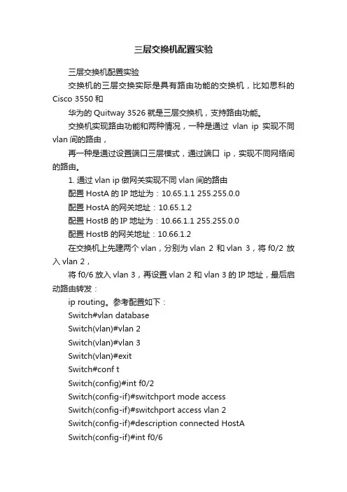
三层交换机配置实验三层交换机配置实验交换机的三层交换实际是具有路由功能的交换机,比如思科的Cisco 3550和华为的Quitway 3526就是三层交换机,支持路由功能。
交换机实现路由功能和两种情况,一种是通过vlan ip实现不同vlan间的路由,再一种是通过设置端口三层模式,通过端口ip,实现不同网络间的路由。
1. 通过vlan ip做网关实现不同vlan间的路由配置HostA的IP地址为:10.65.1.1 255.255.0.0配置HostA的网关地址:10.65.1.2配置HostB的IP地址为:10.66.1.1 255.255.0.0配置HostB的网关地址:10.66.1.2在交换机上先建两个vlan,分别为vlan 2 和vlan 3,将f0/2 放入vlan 2,将f0/6放入vlan 3,再设置vlan 2 和 vlan 3的IP地址,最后启动路由转发:ip routing。
参考配置如下:Switch#vlan databaseSwitch(vlan)#vlan 2Switch(vlan)#vlan 3Switch(vlan)#exitSwitch#conf tSwitch(config)#int f0/2Switch(config-if)#switchport mode accessSwitch(config-if)#switchport access vlan 2Switch(config-if)#description connected HostASwitch(config-if)#int f0/6Switch(config-if)#switchport mode accessSwitch(config-if)#switchport access vlan 3Switch(config-if)#description connected HostBSwitch(config-if)#exitSwitch(config)#int vlan 2Switch(config-if)#ip address 10.65.1.2 255.255.0.0Switch(config-if)#int vlan 3Switch(config-if)#ip address 10.66.1.2 255.255.0.0Switch(config-if)#exitSwitch(config)#ip routingSwitch(config)#endSwitch#通过以上设置HostA与HostB应该可以ping通了。
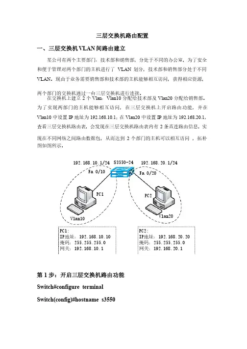
三层交换机路由配置一、三层交换机VLAN 间路由建立某公司有两个主要部门:某公司有两个主要部门:技术部和销售部,技术部和销售部,技术部和销售部,分处于不同的办公室,分处于不同的办公室,分处于不同的办公室,为了安全为了安全和便于管理对两个部门的主机进行了VLAN 划分,技术部和销售部分处于不同VLAN 。
现由于业务需要销售部和技术部的主机能够相互访问,获得相应资源,两个部门的交换机通过一台三层交换机进行连接。
在交换机上建立2个Vlan :Vlan10分配给技术部及Vlan20分配给销售部。
为了实现两部门的主机能够相互访问,在三层交换机上开启路由功能,并在Vlan10中设置IP 地址为192.168.10.1;在Vlan20中设置IP 地址为192.168.20.1,查看三层交换机路由表,会发现在三层交换机路由表内有2条直连路由信息,实现在不同网络之间路由数据包,从而达到2个部门的主机可以相互访问个部门的主机可以相互访问 ,拓朴图如图所示。
图如图所示。
第1步:开启三层交换机路由功能 Switch#configure terminal Switch(config)#hostname s3550 S3550-24Vlan10Vlan20Fa 0/10Fa 0/20PC1PC2192.168.10.1/24192.168.20.1/24PC1:IP IP地址:地址:地址:192.168.10.10192.168.10.10掩码:掩码:255.255.255.0255.255.255.0网关:网关:192.168.10.1192.168.10.1PC2:IP IP地址:地址:地址:192.168.20.20192.168.20.20掩码:掩码:255.255.255.0255.255.255.0网关:网关:192.168.20.1192.168.20.1S3550(conifg)#ip routing第2步:建立Vlan,并分配端口S3550(conifg)#vlan 10S3550(config-vlan)#name salesS3550(config-vlan)#exitS3550(conifg)#vlan 20S3550(config-vlan)#name technicalS3550(config-vlan)#exitS3550(conifg)#S3550(conifg)#interface fastethernet 0/10S3550(conifg-if)#switchport mode accessS3550(conifg-if)#switchport access vlan 10S3550(conifg-if)#exitS3550(conifg)# interface fastethernet 0/20S3550(conifg-if)#switchport mode accessS3550(conifg-if)#switchport access vlan 20S3550(config-vlan)#exitS3550(config)#第3步:配置三层交换机端口的路由功能S3550(config)#interface vlan 10S3550(conifg-if)#ip address 192.168.10.1 255.255.255.0 S3550(conifg-if)#no shutdownS3550(conifg-if)#exitS3550(config)#interface vlan 20S3550(conifg-if)#ip address 192.168.20.1 255.255.255.0 S3550(conifg-if)#no shutdown S3550(conifg-if)#end S3550#第4步:查看路由表 S3550#show ip route第5步:测试三层交换机Vlan 间路由功能二、三层交换机与路由器间静态路由的建立某校园局域网由若干台交换机构成,某校园局域网由若干台交换机构成,现学校需要将校园网接入互联网,现学校需要将校园网接入互联网,现学校需要将校园网接入互联网,学校学校在出口使用一台路由器连接互联网。
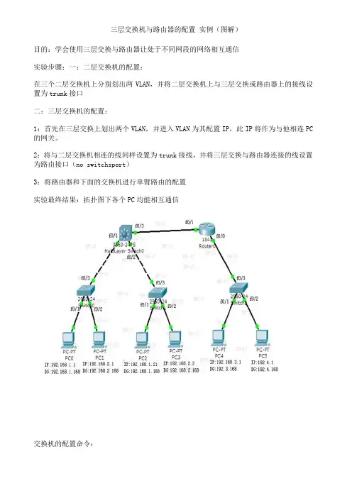
三层交换机与路由器的配置实例(图解)目的:学会使用三层交换与路由器让处于不同网段的网络相互通信实验步骤:一:二层交换机的配置:在三个二层交换机上分别划出两VLAN,并将二层交换机上与三层交换或路由器上的接线设置为trunk接口二:三层交换机的配置:1:首先在三层交换上划出两个VLAN,并进入VLAN为其配置IP,此IP将作为与他相连PC 的网关。
2:将与二层交换机相连的线同样设置为trunk接线,并将三层交换与路由器连接的线设置为路由接口(no switchsport)3:将路由器和下面的交换机进行单臂路由的配置实验最终结果:拓扑图下各个PC均能相互通信交换机的配置命令:SW 0:Switch>Switch>enSwitch#confConfiguring from terminal, memory, or network [terminal]?Enter configuration commands, one per line. End with CNTL/Z.Switch(config)#vlan 2Switch(config-vlan)#exitSwitch(config)#int f0/2Switch(config-if)#switchport access vlan 2Switch(config-if)#no shutSwitch(config-if)#int f0/3Switch(config-if)#switchport mode trunk%LINEPROTO-5-UPDOWN: Line protocol on Interface FastEthernet0/3, changed state to down%LINEPROTO-5-UPDOWN: Line protocol on Interface FastEthernet0/3, changed state to upSwitch(config-if)#exitSwitch(config)#SW 1:Switch>enSwitch#confConfiguring from terminal, memory, or network [terminal]?Enter configuration commands, one per line. End with CNTL/Z.Switch(config)#int f0/2Switch(config-if)#switchport access vlan 2% Access VLAN does not exist. Creating vlan 2Switch(config-if)#no shutSwitch(config-if)#exitSwitch(config)#int f0/3Switch(config-if)#switchport mode trunk%LINEPROTO-5-UPDOWN: Line protocol on Interface FastEthernet0/3, changed state to down%LINEPROTO-5-UPDOWN: Line protocol on Interface FastEthernet0/3, changed state to upSwitch(config-if)#SW 2:Switch>enSwitch#confConfiguring from terminal, memory, or network [terminal]?Enter configuration commands, one per line. End with CNTL/Z.Switch(config)#int f0/2Switch(config-if)#switchport access vlan 2% Access VLAN does not exist. Creating vlan 2Switch(config-if)#exitSwitch(config)#int f0/3Switch(config-if)#switchport mode trunkSwitch(config-if)#三层交换的配置命令:Switch>enSwitch#confConfiguring from terminal, memory, or network [terminal]?Enter configuration commands, one per line. End with CNTL/Z.Switch(config)#int f0/1Switch(config-if)#switchport mode trunk%LINEPROTO-5-UPDOWN: Line protocol on Interface FastEthernet0/2, changed state to downSwitch(config-if)#exitSwitch(config)#int f0/2Switch(config-if)#switchport mode trunkSwitch(config-if)#exitSwitch(config)#vlan 2Switch(config-vlan)#exitSwitch(config)#int vlan 1Switch(config-if)#no shut%LINK-5-CHANGED: Interface Vlan1, changed state to up%LINEPROTO-5-UPDOWN: Line protocol on Interface Vlan1, changed state to up Switch(config-if)#ip address 192.168.1.168 255.255.255.0Switch(config-if)#exitSwitch(config)#int vlan 2%LINK-5-CHANGED: Interface Vlan2, changed state to up%LINEPROTO-5-UPDOWN: Line protocol on Interface Vlan2, changed state to upSwitch(config-if)#ip addSwitch(config-if)#ip address 192.168.2.168 255.255.255.0Switch(config-if)#%LINK-5-CHANGED: Interface FastEthernet0/3, changed state to up%LINEPROTO-5-UPDOWN: Line protocol on Interface FastEthernet0/3, changed state to upSwitch(config-if)#exitSwitch(config)#int f0/3Switch(config-if)#no switchport%LINEPROTO-5-UPDOWN: Line protocol on Interface FastEthernet0/3, changed state to down%LINEPROTO-5-UPDOWN: Line protocol on Interface FastEthernet0/3, changed state to upSwitch(config-if)#Switch(config-if)#ip address 192.168.10.1 255.255.255.0Switch(config-if)#no shutSwitch(config-if)#exitSwitch(config)#ip routingSwitch(config-if)#exitSwitch(config)#ip route 0.0.0.0 0.0.0.0 192.168.10.2Switch(config)#路由器的配置:Router>enRouter#confConfiguring from terminal, memory, or network [terminal]?Enter configuration commands, one per line. End with CNTL/Z.Router(config)#int f0/0Router(config-if)#no shut%LINK-5-CHANGED: Interface FastEthernet0/0, changed state to upRouter(config-if)#exitRouter(config)#int f0/1Router(config-if)#no shut%LINK-5-CHANGED: Interface FastEthernet0/1, changed state to up%LINEPROTO-5-UPDOWN: Line protocol on Interface FastEthernet0/1, changed state to upRouter(config-if)#exitRouter(config)#int f0/0Router(config-if)#no shutRouter(config-if)#exitRouter(config)#int f0/0.1Router(config-subif)#encapsulation dot1Q 1Router(config-subif)#ip address 192.168.3.168 255.255.255.0Router(config-subif)#exitRouter(config)#int f0/0.2Router(config-subif)#encapsulation dot1Q 2Router(config-subif)#ip addRouter(config-subif)#ip address 192.168.4.168 255.255.255.0Router(config-subif)#exitRouter(config)#ip route 0.0.0.0 0.0.0.0 192.168.10.1Router(config)#exit%SYS-5-CONFIG_I: Configured from console by consoleRouter#confConfiguring from terminal, memory, or network [terminal]?Enter configuration commands, one per line. End with CNTL/Z.Router(config)#int f0/1Router(config-if)#ip addRouter(config-if)#ip address 192.168.10.2 255.255.255.0 Router(config-if)#。

三层交换机配置教程三层交换机是一种具有路由功能的交换机,可以实现不同网段之间的互联。
下面是三层交换机配置教程:1. 连接三层交换机:首先,将三层交换机与其他设备(如路由器或防火墙)进行连接,可以使用网线将它们连接起来。
确保连接的端口是正确的并且连接松紧适中。
2. 访问三层交换机:使用终端或电脑连接到三层交换机的管理端口。
通常,可以通过SSH或Telnet协议访问交换机的管理接口。
3. 进入交换机的命令行界面:成功连接到三层交换机后,输入正确的用户名和密码,进入交换机的命令行界面。
用户名和密码通常是事先设置好的。
4. 设置主机名:在交换机命令行界面中,使用命令"hostname [名称]"来设置交换机的主机名。
主机名可以是任何你喜欢的名称,但通常建议使用简洁的描述性名称。
5. 配置IP地址:使用命令"interface [接口号]"进入交换机的接口配置模式。
然后,使用"ip address [IP地址] [子网掩码]"命令为每个接口设置IP地址和子网掩码。
确保IP地址和子网掩码与网络规划一致。
6. 启用接口:为了使接口生效,使用"no shutdown"命令启用每个接口。
这将使接口进入工作状态。
7. 配置路由:三层交换机可以实现不同网段之间的路由功能。
为了配置路由,使用"ip route [目标网络] [目标子网掩码] [下一跳地址]"命令。
这将指定该网络的下一跳地址。
可以添加多个路由以实现完整的路由表。
8. 保存配置:确认完成配置后,使用命令"copy running-config startup-config"保存配置。
这将保存当前正在运行的配置为交换机的启动配置,以便在重新启动后仍然有效。
以上就是三层交换机配置的基本步骤。
根据实际需求,还可以进行更复杂的配置,如VLAN划分、安全设置、负载均衡等。
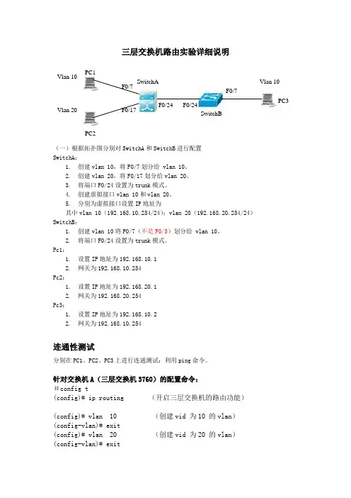
三层交换机路由实验详细说明(一)根据拓扑图分别对SwitchA 和SwitchB 进行配置SwitchA :1. 创建vlan 10,将F0/7划分给 vlan 10。
2. 创建vlan 20,将F0/17划分给vlan 20。
3. 将端口F0/24设置为trunk 模式。
4. 创建虚拟接口vlan 10和vlan 20。
5. 分别为虚拟接口设置IP 地址为其中vlan 10(192.168.10.254/24);vlan 20(192.168.20.254/24)SwitchB :1. 创建vlan 10将F0/7(不是F0/5)划分给 vlan 10。
2. 将端口F0/24设置为trunk 模式。
Pc1:1. 设置IP 地址为192.168.10.12. 网关为192.168.10.254Pc2:1. 设置IP 地址为192.168.20.12. 网关为192.168.20.254Pc3:1. 设置IP 地址为192.168.10.22. 网关为192.168.10.254连通性测试分别在PC1、PC2、PC3上进行连通测试:利用ping 命令。
针对交换机A (三层交换机3760)的配置命令:#config t(config)# ip routing (开启三层交换机的路由功能)(config)# vlan 10 (创建vid 为10 的vlan )(config-vlan)# exit(config)# vlan 20 (创建vid 为20 的vlan )(config-vlan)# exit PC2 SwitchA PC1PC3 F0/24 Vlan 20 F0/24 Vlan 10 F0/7 F0/17 Vlan 10 F0/7 SwitchB(config)# int fast 0/7(config-if)# switch mode access(config-if)# switch access vlan 10 (将0/7端口加入vlan 10中) (config-if)# exit(config)# int fast 0/17(config-if)# switch mode access(config-if)# switch access vlan 20 (将0/17端口加入vlan 20中) (config-if)# exit(config)# int fast 0/24(config-if)# switch mode trunk (将0/24设为trunk模式)(config-if)# switch trunk allowed vlan all (此命令可以不必输入,因为默认是全部允许)(config-if)# exit(创建虚拟接口vlan 10,并设置IP地址和掩码:)(config)# int vlan 10(config-if)# ip addr 192.168.10.254 255.255.255.0(config-if)# exit(创建虚拟接口vlan 20,并设置IP地址和掩码:)(config)# int vlan 20(config-if)# ip addr 192.168.20.254 255.255.255.0(config-if)# exit针对交换机B(二层交换机2126)的配置命令:#config t(config)# vlan 10 (创建vid 为10 的vlan)(config-vlan)# exit(config)# int fast 0/7(config-if)# switch mode access(config-if)# switch access vlan 10 (将0/7端口加入vlan 10中) (config-if)# exit(config)# int fast 0/24(config-if)# switch mode trunk (将0/24设为trunk模式)(config-if)# switch trunk allowed vlan all (此命令可以不必输入,因为默认是全部允许)(config-if)# exit注意:(一)配置好交换机之后不要任意插拔网线,否则要重新配置有关的端口。
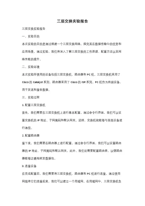
三层交换实验报告三层交换实验报告一、实验目的本次实验的目的是通过搭建一个三层交换网络,探究其在数据传输中的优势和应用场景。
通过实验,我们将深入了解三层交换的工作原理、配置方法以及网络性能的提升。
二、实验环境本次实验所使用的设备包括三层交换机、路由器和PC机。
三层交换机采用了Cisco的Catalyst系列,路由器采用了Cisco的ISR系列。
PC机作为终端设备,用于发送和接收数据。
三、实验过程1. 配置三层交换机首先,我们需要在三层交换机上进行基本配置。
通过命令行界面,我们可以设置交换机的IP地址、子网掩码和默认网关。
这样,交换机就能够与其他设备进行通信。
2. 配置路由器接下来,我们需要在路由器上进行配置。
通过命令行界面,我们可以设置路由器的IP地址、子网掩码和默认网关。
此外,我们还需要配置路由表,以便路由器能够正确地转发数据包。
3. 连接设备在完成配置后,我们需要将三层交换机、路由器和PC机进行连接。
通过使用网线将它们连接起来,我们可以建立一个局域网。
在局域网中,三层交换机负责交换数据包,路由器负责转发数据包,PC机作为终端设备进行数据的发送和接收。
4. 测试网络性能在搭建好网络之后,我们可以进行性能测试。
通过发送大量的数据包,我们可以测试网络的吞吐量和延迟。
三层交换机的优势在于它能够根据目的IP地址来转发数据包,从而提高网络的传输效率。
而传统的二层交换机只能根据MAC 地址来转发数据包,效率较低。
四、实验结果经过测试,我们发现三层交换机在数据传输中的确具有一定的优势。
相比于传统的二层交换机,三层交换机能够更快地转发数据包,从而提高了网络的传输效率。
此外,三层交换机还支持更多的网络协议,可以满足更多的应用需求。
五、实验总结通过本次实验,我们深入了解了三层交换的工作原理和配置方法。
三层交换机在现代网络中扮演着重要的角色,它能够提高网络的传输效率和性能。
在实际应用中,我们可以将三层交换机应用于大型企业网络、数据中心等场景,以满足高速、大容量的数据传输需求。
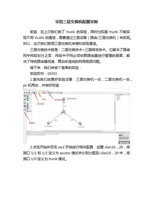
实验三层交换机配置实例前言:在上次我们做了trunk的实验,同时也知道trunk不能实现不同VLAN间通信,需要通过三层设备(路由/三层交换机)来实现。
所以,这次我们就用三层交换机来模拟实现通信。
三层交换技术就是:二层交换技术+三层转发技术。
它解决了局域网中网段划分之后,网段中子网必须依赖路由器进行管理的局面,解决了传统路由器低速、复杂所造成的网络瓶颈问题。
接下来,我们来做个简单的实验:实验软件:GNS31.首先我们放置好实验设备:三层交换机一台,二层交换机一台,pc机两台,并做好标签:2.点击开始并双击sw2开始进行相关配置:创建vlan10,20,将端口1/1和1/2定义为access模式并分别分配到vlan10,20中,将端口1/0定义为trunk模式。
3.双击三层交换机sw1进行相关配置:创建vlan10,20,将端口1/0定义为trunk模式,给虚拟接口vlan10,20配置ip。
4.最后我们给两台pc机配上ip:5.此时配置已全部完成,最后见证奇迹的时刻:可以看到两台pc都能互相通信。
总结:第三层交换机的设计基于对IP路由的仔细分析,把IP路由中每个报文都必须经过的过程提取出来,这个过程是十分简化的过程。
IP路由中绝大多数报文是不包含选项的报文,因此在多数情况下处理报文IP选项的工作是多余的。
不同网络的报文长度是不同的,为了适应不同的网络,IP要实现报文分片的功能,但是在全以太网的环境中,网络的帧长度是固定的,因此报文分片也是一个可以省略的工作。
第三层交换技术没有采用路由器的最长地址掩码匹配的方法,而是使用了精确地址匹配的方法处理,这样,有利于硬件的实现快速查找。
它采用了使用高速缓存的方法,经常使用的主机路由放到了硬件查找表中,只有在这个高速缓存中无法匹配的项目才会通过软件去转发。
在存储转发过程中使用了流交换方式,在流交换中,分析第一个报文确定其是否表示了一个流或者一组具有相同源地址和目的地址的报文。
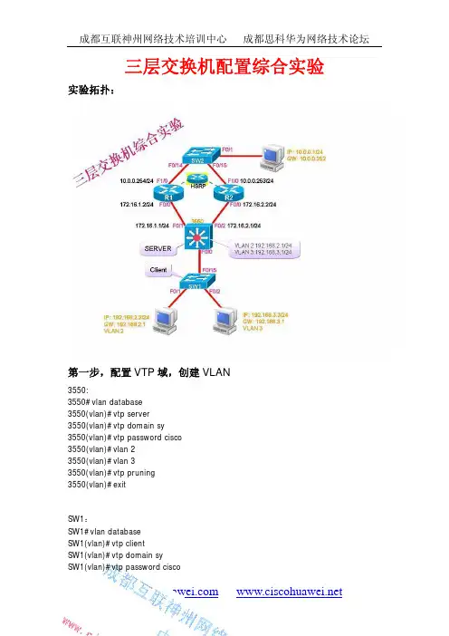
三层交换机配置综合实验实验拓扑:第一步,配置VTP域,创建VLAN3550:3550#vlan database3550(vlan)#vtp server3550(vlan)#vtp domain sy3550(vlan)#vtp password cisco3550(vlan)#vlan 23550(vlan)#vlan 33550(vlan)#vtp pruning3550(vlan)#exitSW1:SW1#vlan databaseSW1(vlan)#vtp clientSW1(vlan)#vtp domain sySW1(vlan)#vtp password ciscoSW1(vlan)#exit第二步,设置中继3550:3550(config)#int f0/03550(config-if)#switchport trunk encapsulation dot1q 3550(config-if)#switchport mode trunk3550(config-if)#end3550#show vtp statusVTP Version : 2Configuration Revision : 2Maximum VLANs supported locally : 256Number of existing VLANs : 7VTP Operating Mode : ServerVTP Domain Name : syVTP Pruning Mode : EnabledVTP V2 Mode : DisabledVTP Traps Generation : DisabledSW1:SW1(config)#int f0/15SW1(config-if)#switchport trunk encapsulation dot1q SW1(config-if)#switchport mode trunkSW1(config-if)#endSW1#show vtp statusVTP Version : 2Configuration Revision : 2Maximum VLANs supported locally : 256Number of existing VLANs : 7VTP Operating Mode : ClientVTP Domain Name : syVTP Pruning Mode : EnabledVTP V2 Mode : DisabledVTP Traps Generation : Disabled第三步,端口加入VLANSW1:SW1#conf tSW1(config)#int f0/1SW1(config-if)#switchport mode accessSW1(config-if)#switchport access vlan 2SW1(config-if)#exitSW1(config-if)#switchport mode accessSW1(config-if)#switchport access vlan 3SW1(config-if)#end第四步,配置三层交换,实现VLAN之间互通35503550#conf t3550(config)#ip routing3550(config)#int vlan 23550(config-if)#ip address 192.168.2.1 255.255.255.03550(config-if)#no shutdown3550(config-if)#exit3550(config)#int vlan 33550(config-if)#ip address 192.168.3.1 255.255.255.03550(config-if)#no shutdown3550(config-if)#end第五步,客户机验证PC1#ping 192.168.3.3Type escape sequence to abort.Sending 5, 100-byte ICMP Echos to 192.168.3.3, timeout is 2 seconds:!!!!!Success rate is 100 percent (5/5), round-trip min/avg/max = 216/284/336 ms PC2#ping 192.168.2.2T ype escape sequence to abort.Sending 5, 100-byte ICMP Echos to 192.168.2.2, timeout is 2 seconds:!!!!!Success rate is 100 percent (5/5), round-trip min/avg/max = 144/211/276 ms第六步,在三层交换机上启用路由功能3550:3550(config)#int f0/13550(config-if)#no switchport3550(config-if)#ip address 172.16.1.1 255.255.255.03550(config-if)#no shutdown3550(config-if)#exit3550(config)#int f0/23550(config-if)#no switchport3550(config-if)#ip address 172.16.2.1 255.255.255.03550(config-if)#no shutdown第七步,配置两台路由器,并启用HSRPR1:R1(config)#R1(config)#int f0/0R1(config-if)#no ip addressR1(config-if)#ip address 172.16.1.2 255.255.255.0R1(config-if)#no shutdownR1(config-if)#speed 100R1(config-if)#duplex fullR1(config-if)#exitR1(config)#int f1/0R1(config-if)#ip address 10.0.0.254 255.255.255.0R1(config-if)#no shutdownR1(config-if)#speed 100R1(config-if)#duplex fullR1(config-if)#standby 1 ip 10.0.0.252R1(config-if)#standby 1 priority 200R1(config-if)#standby 1 preemptR1(config-if)#standby 1 track f0/0 10R1(config-if)#endR1#show standby briefP indicates configured to preempt.|Interface Grp Prio P State Active Standby Virtual IP Fa1/0 1 200 P Active local 10.0.0.253 10.0.0.252 R2:R2#conf tR2(config)#int f0/0R2(config-if)#ip address 172.16.2.2 255.255.255.0R2(config-if)#no shutdownR2(config-if)#speed 100R2(config-if)#duplex fullR2(config-if)#exitR2(config)#int f1/0R2(config-if)#ip address 10.0.0.253 255.255.255.0R2(config-if)#no shutdownR2(config-if)#speed 100R2(config-if)#duplex fullR2(config-if)#standby 1 ip 10.0.0.252R2(config-if)#end第八步,配置动态路由协议3550:3550(config)#router ospf 13550(config-router)#network 192.168.2.0 0.0.0.255 area 03550(config-router)#network 192.168.3.0 0.0.0.255 area 03550(config-router)#network 172.16.1.0 0.0.0.255 area 03550(config-router)#network 172.16.2.0 0.0.0.255 area 03550(config-router)#endR1:R1(config)#router ospf 2R1(config-router)#network 172.16.1.0 0.0.0.255 area 0R1(config-router)#network 10.0.0.0 0.0.0.255 are 0R1(config-router)#endR2:R2(config)#router ospf 3R2(config-router)#network 172.16.2.0 0.0.0.255 area 0R2(config-router)#network 10.0.0.0 0.0.0.255 area 0R2(config-router)#endR2#show ip route Gateway of last resort is not set172.16.0.0/24 is subnetted, 2 subnetsO 172.16.1.0 [110/2] via 172.16.2.1, 00:03:39, FastEthernet0/0[110/2] via 10.0.0.254, 00:03:39, FastEthernet1/0C 172.16.2.0 is directly connected, FastEthernet0/010.0.0.0/24 is subnetted, 1 subnetsC 10.0.0.0 is directly connected, FastEthernet1/0O 192.168.2.0/24 [110/2] via 172.16.2.1, 00:03:39, FastEthernet0/0O 192.168.3.0/24 [110/2] via 172.16.2.1, 00:03:39, FastEthernet0/0第九步,客户机验证PC3#ping 192.168.2.2、Type escape sequence to abort.Sending 5, 100-byte ICMP Echos to 192.168.2.2, timeout is 2 seconds:!!!!!Success rate is 100 percent (5/5), round-trip min/avg/max = 288/337/432 ms PC3#ping 192.168.3.3Type escape sequence to abort.Sending 5, 100-byte ICMP Echos to 192.168.3.3, timeout is 2 seconds:!!!!!Success rate is 100 percent (5/5), round-trip min/avg/max = 240/300/336 ms PC1#ping 192.168.3.3Type escape sequence to abort.Sending 5, 100-byte ICMP Echos to 192.168.3.3, timeout is 2 seconds:!!!!!Success rate is 100 percent (5/5), round-trip min/avg/max = 192/231/288 ms。
三层交换机路由功能配置实验总结三层交换机作为一种网络交换设备,除了基本的交换功能外,还具备了路由功能。
在网络中,路由功能是至关重要的,因为它可以实现不同子网之间的通信。
本文将介绍如何通过三层交换机实现路由功能,并进行实验总结。
一、实验环境本次实验环境如下:1. 三台计算机,分别连接在三个不同的子网中,IP地址分别为:- 192.168.1.2/24- 192.168.2.2/24- 192.168.3.2/242. 三层交换机,具备路由功能,连接以上三个子网。
二、实验步骤1. 配置三层交换机的接口IP地址三层交换机需要为每个接口分配IP地址,以便能够在不同的子网之间进行路由转发。
在本次实验中,我们需要为三个接口分别配置IP 地址:- 接口 VLAN 1:192.168.1.1/24- 接口 VLAN 2:192.168.2.1/24- 接口 VLAN 3:192.168.3.1/24可以通过以下命令进行配置:```interface vlan 1ip address 192.168.1.1 255.255.255.0no shutdowninterface vlan 2ip address 192.168.2.1 255.255.255.0no shutdowninterface vlan 3ip address 192.168.3.1 255.255.255.0no shutdown```2. 配置路由为了实现不同子网之间的通信,需要在三层交换机中配置路由。
在本次实验中,我们需要将两个子网之间的路由添加到路由表中。
假设需要从192.168.1.0/24子网中的计算机访问192.168.3.0/24子网中的计算机,需要将192.168.3.0/24子网的路由添加到路由表中。
可以通过以下命令进行配置:```ip route 192.168.3.0 255.255.255.0 192.168.2.2```其中,192.168.3.0 255.255.255.0表示需要访问的目标子网,192.168.2.2表示下一跳路由器的IP地址。
实验三三层交换机设置一、实验目的配置三层交换机的三层功能,实现路由作用。
二、实验设备三层交换机(1台)、主机(2台)、直连线(2条)三、实验原理三层交换机是在二层交换的基础上实现了三层的路由功能。
三层交换机基于“一次路由,多次交换”的特性,在局域网环境中转发性能远远高于路由器。
而且三层交换机同时具备二层的功能,能够和二层的交换机进行很好的数据转发。
三层交换机的以太网接口要比一般的路由器多很多,更加适合多个局域网段之间的互联。
三层交换机的所有端口在默认情况下都属于二层端口,不具备路由功能。
不能给物理端口直接配置IP地址。
但可以开启物理端口的三层路由功能。
三层交换机默认开启了路由功能,可利用ip routing命令进行控制。
四、实验内容本实验完成的是开启三层交换机物理端口的路由功能,使其完成不同网段数据的转发。
按图3所示连接设备,三层交换机采用锐捷S3550,PCA与PCB分别连接到三层交换机两端口(F0/5,F0/15)上,连接线为直连双绞线。
两台PC分别配置IP地址与子网掩码,使其不属于同一网段。
用PING命令测试二者的连通性。
开启三层交换机及其端口的三层功能,为接口F0/5、F0/15配置IP地址与掩码,使F0/5与PCA属同一网段,F0/15与PCB属同一网段。
配置PCA网关地址为F0/5地址,配置PCB网关地址为F0/15地址。
再测试各计算机的连通性。
图3 三层交换机实验拓扑五、实验步骤步骤1:连线并配置PCA 、PCB 的IP 地址,如图3所示。
步骤2:测试PCA 、PCB 连通性,并分析原因。
步骤3:开启三层交换机的路由功能。
switch#configure terminalswitch(config)#hostname s3550!为交换机更改名称 s3550(config)#ip routing !开启三层交换机的路由功能 步骤4:配置三层交换机端口的路由功能。
s3550(config)#interface fastethernet 0/5s3550(config-if)#no switchport !开启交换机端口路由功能s3550(config-if)#ip address 192.168.5.1 255.255.255.0!为交换机端口配置IP 地址 s3550(config-if)#no shutdowns3550(config-if)#end同样方法,为F0/15做相应配置。
登录3100,输入如下命令:System-viewInterface vlan-interface 1 //进入默认的VLAN端口,vlan 1 Ip address 24 //设置本机在VLAN 1 中的IP 地址Quitsave登录5100,输入如下命令:System-viewInterface vlan-interface 1Ip address 24Quitsave登录5600,输入如下命令:System-viewInterface vlan-interface 1Ip address 24Quitsave在3100上输入:PingPing同理在5100上也输入:PingPing同理在5600上也输入:PingPing至此,交换机之间的管理vlan 就可以互相通信。
三、开启TELNET登录3100,输入如下命令:System-viewUser-interface vty 0 4 //进入用户端口Authenticate-mode scheme //设置认证模式Protocol inbound all //允许telnet 和RSH 访问User privilege level 3 //设置访问级别QuitLocal-user iamcat //创建本地用户Password simple xxxxxx //设置密码Service-type telnet //访问服务类型:telnetLevel 3 //设置授权访问级别Save在5100或5600上,即可用telnet 配置3100交换机。
登录5100,输入如下命令:System-viewUser-interface vty 0 4Authenticate-mode schemeProtocol inbound allUser privilege level 3QuitLocal-user iamcatPassword simple xxxxxxService-type telnetLevel 3QuitSave在3100或5600上,即可用telnet 配置5100交换机。
页眉内容实验名称:3层交换机配置一.实验目的和要求了解DES-3326SR的虚端口的设置了解单台DES 3326SR直接路由的设置了解多台DES 3326SR静态路由的设置二.实验原理和内容1.网络硬件环境的准备2.对等网络的建立3.通过交换机实现VLAN的划分与通信4.通过路由器实现不同VLAN之间的通信5.无线局域网的组建三、实验步骤步骤1:交换机1,2VLAN配置分别配置交换机1,交换机2的VLAN,保证每个交换机至少各有2个VLAN 可以正常工作,假设:交换机1(VLAN2和VLAN3)交换机2(VLAN6和VLAN7)注:配置指令参见实验1,这里不再详细说明步骤2:交换机1,2虚接口配置分别为交换机1,交换机2的每个VLAN配置虚接口,1:配置指令为:Create ipif <虚接口名称><虚接口IP地址>/<子网掩码长度><虚接口对应的vlan名称>例如:create ipif 192.168.2.1/24 vlan22:查看指令为:Show ipif步骤3:交换机1,2级联端口配置分别为交换机1,交换机2创建VLAN5,VLAN5成员为两台交换机的级联端口(即两交换机的连线端口号),同时创建VLAN的虚接口配置1:配置指令为:a.两台交换机均执行如下指令,创建vlan5,并增加级联端口Create vlan vlan5 tag 5Congfig vlan vlan5 add untag 2b.两台交换机均执行如下指令,创建vlan5虚接口Create ipif if5 192.168.5.1/24 vlan5 state enableCreate ipif if5 192.168.5.2/24 vlan5 state enable注:此处两个虚接口属于同一网段,不允许使用相同的IP地址步骤4:交换机路由配置分别为交换机1,交换机2创建静态路由a.交换机1Create iproute 192.168.2.0/24 192.168.5.1Create iproute 192.168.3.0/24 192.168.5.1b.交换机2Create iproute 192.168.6.0/24 192.168.5.2Create iproute 192.168.7.0/24 192.168.5.2步骤5:测试配置结束后,VLAN2,VLAN3,VLAN6,VLAN7能够全部互通实验名称:3层交换机配置一.实验目的和要求了解DES-3326SR的虚端口的设置了解单台DES 3326SR直接路由的设置了解多台DES 3326SR静态路由的设置二.实验原理和内容1.网络硬件环境的准备2.对等网络的建立3.通过交换机实现VLAN的划分与通信4.通过路由器实现不同VLAN之间的通信5.无线局域网的组建三.主要仪器设备Dlink-3624SR交换机*2四.实验步骤步骤1:交换机1,2VLAN配置分别配置交换机1,交换机2的VLAN,保证每个交换机至少各有2个VLAN 可以正常工作,假设:交换机1(VLAN2和VLAN3)交换机2(VLAN6和VLAN7)注:配置指令参见实验1,这里不再详细说明步骤2:交换机1,2虚接口配置分别为交换机1,交换机2的每个VLAN配置虚接口,1:配置指令为:Create ipif <虚接口名称><虚接口IP地址>/<子网掩码长度><虚接口对应的vlan名称>例如:create ipif 192.168.2.1/24 vlan22:查看指令为:Show ipif步骤3:交换机1,2级联端口配置分别为交换机1,交换机2创建VLAN5,VLAN5成员为两台交换机的级联端口(即两交换机的连线端口号),同时创建VLAN的虚接口配置1:配置指令为:a.两台交换机均执行如下指令,创建vlan5,并增加级联端口Create vlan vlan5 tag 5Congfig vlan vlan5 add untag 2b.两台交换机均执行如下指令,创建vlan5虚接口Create ipif if5 192.168.5.1/24 vlan5 state enableCreate ipif if5 192.168.5.2/24 vlan5 state enable注:此处两个虚接口属于同一网段,不允许使用相同的IP地址步骤4:交换机路由配置分别为交换机1,交换机2创建静态路由a.交换机1Create iproute 192.168.2.0/24 192.168.5.1Create iproute 192.168.3.0/24 192.168.5.1b.交换机2Create iproute 192.168.6.0/24 192.168.5.2Create iproute 192.168.7.0/24 192.168.5.2步骤5:测试配置结束后,VLAN2,VLAN3,VLAN6,VLAN7能够全部互通五.实验记录和处理VLAN及端口配置:交换机1:交换机2:网关配置:交换机1:交换机2:交换机1:2实验结果截图:口配置正确,交换机路由配置正确,不同VLAN间能够通过它们互相连通。
三层交换机及其基本配置实验报告三层交换机及其基本配置实验报告范文篇一:交换机基本配置及VLAN配置实验报告一、掌握交换机的基本使用方法【基本原理】1、交换机的管理方法简述交换机的管理方式基本分为两种:带内管理和带外管理。
带外管理是通过交换机的Console口管理交换机,不占用交换机的网络接口,特点是需要使用配置线缆,近距离配置。
第一次配置交换机时必须利用Console端口进行配置。
带内管理是占用交换机的一个通信接口,通过telnet方式管理交换机,可以远距离配置。
交换机管理主要通过命令行完成。
交换机的命令行操作模式,主要包括:用户模式、特权模式、全局配置模式、端口模式等几种。
各种模式提供一组命令,实现特定的一组功能。
第一级,用户模式:进入交换机后得到的第一个操作模式,该模式下可以简单查看交换机的软、硬件版本信息,并进行简单的测试。
第二级,特权模式:由用户模式进入的下一级模式,该模式下可以对交换机的配置文件进行管理,查看交换机的配置信息,进行网络的测试和调试等。
第三级,全局配置模式:由特权模式进入的下一级模式,该模式下可以配置交换机的全局性参数(如设备名、登录时的描述信息等)。
第四级,全局配置模式下有多个并列的子模式,分别对交换机具体的功能进行配置。
如,端口模式:对交换机的端口进行参数配置。
VLAN描述:对交换机的VLAN进行参数配置。
设,交换机名称为switch,各种模式的提示符和进入方式小结如下表:Exit命令:退回到上一级操作模式。
End命令是指用户从特权模式以下级别直接返回到特权模式。
注意区别每个操作模式下可执行的命令种类,交换机不可以跨模式执行命令。
2、交换机命令行支持以下功能(见实验步骤)1) 获取帮助信息:?2) 命令的简写:输入前几个字符3) 命令的自动补齐:按Tab键4) 命令的快捷键功能:Ctrl+z:退回到特权模式Ctrl+c:终止当前操作等【实验设备】Cisco Packet Tracer:3台计算机和1台交换机【实验步骤】1. 进入特权模式Switch>enSwitch#2. 显示交换机上的VLAN配置Switch#show vlan !显示交换机已有的VLAN配置,这些VLAN含有哪些端口3. 进入全局配置模式Switch#configure terminalSwitch(config)#4. 配置交换机的名字为S2 Switch (config)# hostname S2 !交换机名称的有效字符是22个。
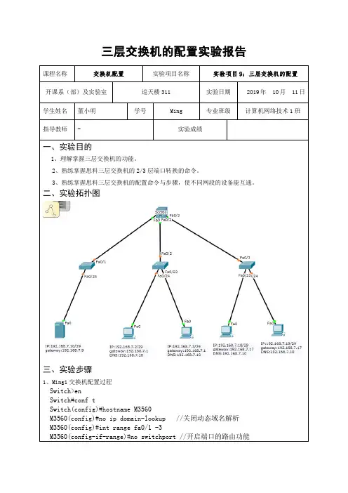
三层交换机vlan配置
实验目的:
1.会使用三层交换机的路由功能。
2.会进行三层交换机与二层交换机之间的vlan配置。
实验步骤:
一、绘制实验拓扑如下:
二、配置S1、S2、S3间的Trunk(中继链路)
S1(config)#int range f0/1 -2
S1(config-if-range)#sw mo trunk
S2(config)#int f0/1
S2(config-if)#sw mo trunk
S3(config)#int f0/1
S3(config-if)#sw mo trunk
三、配置VTP并创建vlan
S1(config)#vtp mode server
Device mode already VTP SERVER.
S1(config)#vtp domain 123
S2(config)#vtp mode client
Setting device to VTP CLIENT mode.
S2(config)#vtp domain 123
S3(config)#vtp mode client
Setting device to VTP CLIENT mode.
S3(config)#vtp domain 123
//以上配置S1为VTP服务器模式,配置S2、S3为客户端模式S1(config)#vlan 2
S1(config)#vlan 3
//以上利用VTP在S1、S2、S3上创建vlan2、vlan3
四、配置三层交换机S1的路由功能下的vlan
S1(config)#ip routing //打开三层交换机的路由功能
S1(config)#int vlan 2
S1(config-if)#ip add 192.168.2.1 255.255.255.0
S1(config-if)#no shut //启用vlan2
//以上为vlan2配置ip
S1(config)#int vlan 3
S1(config-if)#ip add 192.168.3.1 255.255.255.0
S1(config-if)#no shut //启用vlan3
//以上为vlan3配置ip
五、配置S2、S3交换机的vlan接口
S2(config)#int f0/3
S2(config-if)#switchport access vlan 2 //端口f0/3划入vlan 2
S2(config)#int f0/4
S2(config-if)#switchport access vlan 3 //端口f0/4划入vlan 3
S3(config)#int f0/3
S3(config-if)#switchport access vlan 2 //端口f0/3划入vlan 2
S3(config)#int f0/4
S3(config-if)#switchport access vlan 3 //端口f0/4划入vlan3
六、主机配置
主机1、3分配192.168.2.0网段地址,网关为:192.168.2.1
主机2、4分配192.168.3.0网段地址,网关为:192.168.3.1
七、测试连通性
配置完成后,两个VLAN(VLAN2、VLAN3)就可以通过三层交换机进行通信了。
在分别属于不同VLAN的主机(1、2、3、4)之间使用ping命令测试VLAN间路由配置的正确性。
能ping通即表示两个不同VLAN 之间实现通信。