AU-YK04解码接收模块规格说明书
- 格式:doc
- 大小:177.00 KB
- 文档页数:3
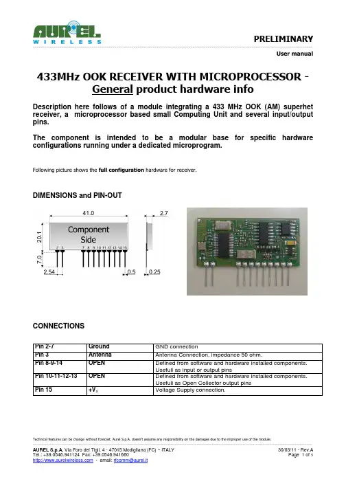
User manualTechnical features can be change without forecast. Aurel S.p.A. doesn’t assume any responsibility on the damages due to the improper use of the module.433MHz OOK RECEIVER WITH MICROPROCESSOR -General product hardware infoDescription here follows of a module integrating a 433 MHz OOK (AM) superhet receiver, a microprocessor based small Computing Unit and several input/output pins.The component is intended to be a modular base for specific hardware configurations running under a dedicated microprogram.Following picture shows the full configuration hardware for receiver.DIMENSIONS and PIN-OUTCONNECTIONSPin 2-7 Ground GND connectionPin 3Antenna Antenna Connection, impedance 50 ohm.Pin 8-9-14 OPEN Defined from software and hardware installed components. Usefull as input or output pinsPin 10-11-12-13 OPEN Defined from software and hardware installed components. Usefull as Open Collector output pins Pin 15+V s Voltage Supply connection.User manual Technical DataMin Tipico Max Unità Annotazioni Receiver frequency 433.92 MHzSupply V s 4,5 5 5,5 VCurrent at full RF and microP function 12 14 mARF sensitivity -109 -111 -113 dBmPass bandwith at –3dB 280 KHzWork Temperature -20 +80 CDimensions 41 x 20.1 x 2.7 mmHardware configuration modularity- RECEIVER UNIT: based on AUREL RX 4MM5 , with low profile crystall as used in in RX 4MM5X++. Front end SAW filter available. Digital filter for motors inducted output interferring signals available.- MICROPROCESSOR: Basic hardware is mounted with a PIC16F636. Any other PIC with same pin out can be mounted.Also ATMEL selected microP can be mounted.- ADDED EXTERNAL MEMORY: Installation place provided for SOT23 PinOut Ic (examples: Microchip 24AA16 or 24LC32)Technical features can be change without forecast. Aurel S.p.A. doesn’t assume any responsibility on the damages due to the improper use of the module.User manual VERSION 6500201168G PRELIMINARY specific InfoPin OUTPin 2-7 Ground GND connectionPin 3 Antenna Antenna Connection, impedance 50 ohm.Pin 8 RSSI Analog voltage signal proportional to received RF signalstrenghtPin 9 Key Connection to external push button (other contact to GND).Push buttons used to RESET microprocessor, teach in newtransmitters, etc...Pin 10-11-12-13 Output pins Output signals paired to keyfob(s) button being pressed (seeLEARN IN). Max 100mA Max 40VPin14 LED Direct connection to LED anode (no load resistor needed). LEDcatode to GNDPin 15 +V s Voltage Supply connection.Hardware configuration.- No receiver Front End Filter installed- No output signal digital filter installed- Microprocessor installed: PIC16F636- No additional memory Ic installed.Software configuration- Can "learn in" up to 10 hand transmitters.- Hand transmitters with Max. 4 buttons.- Duty Cycle (software turns receiver on for 1 millisecond every 100 millisecond quiescent)- Decoder can recognize Microchip KEELOQ MODIFIED frames . The associated transmitter, therefore, must generate the frame from a PIC running a modified KEELOQ code generation software, rather than from a normal HCS300/301 Ic. (This is obtained using a microprocessor in the transmitter circuit).- Released software validates modified KEELOQ frames identified with the "AUREL standard Manufacturing Code" and related parameters.- Each Output pin can be set to mono or bystable operation (when ANY output is set to bystable operation and this specific output is in ON condition, the receiver looses the duty cycle timing and therefore sets to FULL 7mA current consumption).Technical features can be change without forecast. Aurel S.p.A. doesn’t assume any responsibility on the damages due to the improper use of the module.User manual Model specific Electrical Characteristics:Min Tipico Max Unità Annotazioni Receiver quiescent average current 100 microAmpLEARN In proceduresClearing memory (memory reset)To clear memory and to erase Receiver memorized data (=reference to already trained in transmitters and related key button), press and realease the button connected to pin 9, LED will start to flash for 10 seconds. Push and keep pressed the button for few seconds, at least. The LED, after 3 seconds, will go ON, indicating that push button can be released. The complete reset function will be indicated from 5 flashes from LED.A cleared module will not recognize any more any of keyfobs previously learned in and will have all four EXITS to monostable.Transmitter(s) learning procedureMAX 10 transmitters acceptedWhen the decoder module/card is powered up, the LED will light up for about 1 second: this indicates a correct function of item.Press and release the connected push button to have the LED going ON and OFF (1 second cycle) for 12 seconds. Press button “A” of your keyfob during the 12 seconds to associate this button of the transmitter being used to EXIT 1 of Module/Card.Press and release the connected push button to have the LED going ON TWICE (fast timing) and then OFF for 1 second: this cycle will be executed for 12 seconds. Press button “B” of your keyfob during the 12 seconds to associate this button of the transmitter being used to EXIT 2 of Module/Card.Press and release, for the third time, the connected push button to have the LED going ON THREE TIMES (fast timing) and then OFF for 1 second: this cycle will be executed for 12 seconds. Press button “C” of your keyfob during the 12 seconds to associate this button of the transmitter being used to EXIT 3 of Module/Card.Press and release, for the forth time, the connected push button to have the LED going ON FOUR TIMES (fast timing) and then OFF for 1 second: this cycle will be executed for 12 seconds. Press button “D” of your keyfob during the 12 seconds to associate this button of the transmitter being used to EXIT 4 of Module/Card.A fifth action on push button will start the learning procedure for a different keyfob (up to 10 transmitters can be learned in).If no more transmitter should be learned in, just let the 12 second time elapse out.Special conditions1. if you try to associate a keyfob button to an EXIT already paired with a button of the sametransmitter, the LED will rapidly flash for 10 second to indicate that the action is not possible.2. When you start to learn in a new transmitter, this will be automatically recognized from the decoder,that will start the full 4 button/Exit pairing.Technical features can be change without forecast. Aurel S.p.A. doesn’t assume any responsibility on the damages due to the improper use of the module.User manualMonostable and bistable outputsSwitching output(s) from monostable to bistable is done, again, via push button.Pressing and releasing , the LED will be flashing for 12 seconds.During this time, press and keep pressed up to full LED ON (keep pressed for about 3 seconds). Release button, LED goes OFF. LED ON/OFF one time will indicate that EXIT 1 is bistable.Repeat for exit 2, 3 and 4 (Led will indicate with ON/OFF sequences what exit is changed)Pls note that change on a specific Exit will be valid for activation from ANY of associated transmitters.Technical features can be change without forecast. Aurel S.p.A. doesn’t assume any responsibility on the damages due to the improper use of the module.。

i s c l ai m e r : T h i s d o c u m e n t a t i o n i s n o t i n t e n d e d a s a s u b s t i t u t e f o r a n d i s n o t t o b e u s e d f o r d e t e r m i n i n g s u i t a b i l i t y o r r e l i a b i l i t y o f t h e s e p r o d u c t s f o r s p e c i f i c u s e r a p p l i c a t i o n sMainRange of productModicon TM3Product or component typeAnalog input module Range compatibility Modicon M241Modicon M251Modicon M221Analogue input number 4Analogue input typeCurrent, analogue input range: 4...20 mACurrent, analogue input range: 0...20 mAVoltage, analogue input range: 0...10 VVoltage, analogue input range: - 10...10 V ComplementaryAnalogue input resolution11 bits + sign 12 bits Permissible continuous overload13 V voltage 40 mA current Input impedance<= 50 Ohm current >= 1 MOhm voltage LSB value 2.44 mV, analogue input: 0...10 V voltage4.88 mV, analogue input: - 10...10 V voltage4.88 µA, analogue input: 0...20 mA current3.91 µA, analogue input:4...20 mA currentConversion time 1 ms + 1 ms per channel + 1 controller cycle timeSampling duration <= 1 msAbsolute accuracy error +/- 0.1 % of full scale at 25 °C+/- 1 % of full scaleTemperature drift +/- 0.006 %FS/°CRepeat accuracy +/-0.5 %FSNon-linearity +/- 0.01 %FSCross talk <= 1 LSB[Us] rated supply voltage 24 V DCSupply voltage limits20.4...28.8 VSurge withstand 1 kV for power supply with common mode protection conforming to EN/IEC 61000-4-50.5 kV for power supply with differential mode protection conforming to EN/IEC 61000-4-51 kV for input with common mode protection conforming to EN/IEC 61000-4-5 Mounting support Top hat type TH35-15 rail conforming to IEC 60715Top hat type TH35-7.5 rail conforming to IEC 60715Plate or panel with fixing kitHeight90 mmDepth70 mmWidth23.6 mmProduct weight0.11 kgEnvironmentStandards EN/IEC 61010-2-201EN/IEC 61131-2Resistance to electrostatic discharge 4 kV on contact conforming to EN/IEC 61000-4-28 kV in air conforming to EN/IEC 61000-4-2Resistance to electromagnetic fields10 V/m at 80 MHz...1 GHz conforming to EN/IEC 61000-4-33 V/m at 1.4 GHz...2 GHz conforming to EN/IEC 61000-4-31 V/m at2 GHz...3 GHz conforming to EN/IEC 61000-4-3Resistance to magnetic fields30 A/m at 50...60 Hz conforming to EN/IEC 61000-4-8Resistance to fast transients 1 kV I/O conforming to EN/IEC 61000-4-4Resistance to conducted disturbances, induced by radio frequency fields 10 V at 0.15...80 MHz conforming to EN/IEC 61000-4-63 V at spot frequency (2, 3, 4, 6.2, 8.2, 12.6, 16.5, 18.8, 22, 25 MHz) conforming to Marine specification (LR, ABS, DNV, GL)Electromagnetic emission Radiated emissions, test level: 40 dBμV/m QP class A (10 m at 30...230 MHz) conforming to EN/IEC55011Radiated emissions, test level: 47 dBμV/m QP class A (10 m at 230 MHz...1 GHz) conforming to EN/IEC 55011Immunity to microbreaks10 msAmbient air temperature for operation-10...55 °C (horizontal installation)-10...35 °C (vertical installation)Ambient air temperature for storage-25...70 °CRelative humidity10...95 % without condensation in operation10...95 % without condensation in storageIP degree of protection IP20Pollution degree2Operating altitude0...2000 mStorage altitude0...3000 mVibration resistance 3.5 mm at 5...8.4 Hz with DIN rail mounting support3 gn at 8.4...150 Hz with DIN rail mounting supportShock resistance15 gn during 11 msOffer SustainabilitySustainable offer status Green Premium productRoHS (date code: YYWW)Compliant - since 1415 - Schneider Electric declaration of conformitySchneider Electric declaration of conformityREACh Reference not containing SVHC above the thresholdReference not containing SVHC above the threshold(*)8.5 mm/0.33 in when the clamp is pulled out.Incorrect Mounting(1)Install a mounting strip Mounting Hole LayoutWiring Diagram (Current / Voltage)(*)Type T fuse (1)Current/Voltage analog output device。
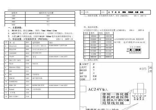
1. RS485通迅,最远1200m . 体积:70mm ×90mm ×24mm
2. AC24V 供电,适用于AC24V 的球形云台 . 可控制三可变镜头、全向云台。
3. 内置10W 开关模块电源,可提供DC12V /500mA 稳压电源给摄像机供电 .
五:接线示意图:
六. 连接示意图:
解码板采用RS485通讯方式的,“A”和“B”为信号接线端,“GND”为屏蔽地,且“A”接RS485设备接口的正端,“B”接RS485设备接口的负端。
6、注意事项:
使用前选择好协议,波特率,解码器地址, 新设置的协议和波特率要重新关断电源5秒再起动后才有效。
协议选择不对、波特率设置不对、485-A、B线极性不对、都将使解码器无法通信。
SA-DV使用说明书
(通用型解码板)
七寸及七寸以上球罩适用
本解码板工作电压为交流24V,千万不可将其直接接入220V 交流市电,切记!!!。

模块的资料原理说明:AU-YK04解码接收模块产品型号:AU-YK04 产品名称:5伏高频超再生四路解码接收模块一、技术参数工作电压(V):DC5V静态电流(mA):4.5MA调制方式:调幅(OOK)工作温度: -10℃~ 70℃接收灵敏度(dBm):-105DB工作频率(MHz):315、433.92MHz(266-433MHZ频率段可任选)编码方式:焊盘编码(固定码)工作方式:M4(点动:按住不松手就输出,一松手就停止输出)、L4(互锁:四路同时只能有一路输出)、T4(自锁:四路相互独立输出、互不影响,按一下输出再按一下停止输出)尺寸(LWH):40*22*7mm二、产品特点:超再生接收模块采用LC振荡电路,内含放大整形,输出的数据信号为解码后的高电平信号,使用极为方便,并且价格低廉,所以被广泛使用。
带四路解码输出(同时也可改为六路点动或互锁输出),使用方便;频点调试容易,供货周期短;产品质量一致性好,性价比高。
接收模块有较宽的接收带宽,一般为±10MHz,出厂时一般调在315MHz或433.92MHZ(如有特殊要求可调整频率,频率的调整范围为266MHz~433MHz。
)。
接收模块一般采用DC5V 供电,如有特殊要求可调整电压范围。
三、脚位及使用说明:脚位名称功能说明1VT输出状态指示2D3数据输出3D2数据输出4D1数据输出5D0数据输出65V电源正极 7GND 电源负极8ANT接天线端接收模块一共有八个外部接口,上面有英文表示。
5V 表示接电源正极, D0、D1、D2、D3 表示输出, GND 表示接电源负极, ANT 表示接天线端。
使用前要接上50欧姆1/4波长的天线,并且天线应该是直的,以达到最佳的接收效果,波长=光速/频率。
四、应用环境(应用领域)无线遥控开关、遥控插座、数据传输、遥控玩具、防盗报警主机、车库门、卷闸门、道闸门、伸缩门等门控业及其遥控音响领域等。
五、自选配件与公司发射系列、遥控器系列产品配套使用。
硅奥科技蓝牙透传模块蓝牙透传模组功能规格书变更记录目录硅奥科技透传模块项目 (2)透传模组功能规格书 (2)1.产品概述 (6)2.应用领域 (6)3.硬件尺寸图 (7)4.pin脚定义 (7)5.电气特性 (8)6.功耗 (10)7.射频特性 (10)8.AT指令集说明 (12)8.1查询3.0蓝牙地址 (12)8.2查询4.0蓝牙地址: (12)8.3查询3.0蓝牙名字: (12)8.4查询4.0蓝牙名字: (13)8.5查询配对码: (13)8.6 查询版本号: (13)8.7查询设备类型: (13)8.8查询蓝牙设备列表(最多支持4个): (14)8.9查询sniff参数: (14)8.10查询最近使用的认证设备: (14)8.11查询蓝牙模块状态: (14)8.12查询rssi: (15)8.13查询已连接设备: (15)8.14查询附近设备: (15)8.15 查询附近LE设备: (16)8.16设置波特率(全波特率): (16)8.17 设置3.0地址: (16)8.18 设置4.0地址: (16)8.19 设置3.0名字: (17)8.20 设置4.0名字: (17)8.21 设置配对码: (17)8.22 设置设备类型: (17)8.23 设置sniff参数: (18)8.24设置设备列表(删): (18)8.25 设置当前工作模式及指定设备: (18)8.26设置当前工作模式: (18)8.27 重置状态: (19)8.28 重连: (19)8.29断开连接: (19)8.30连接(CMODE时): (19)8.31 sniff动作: (19)8.32 可发现模式: (20)8.33 深度休眠:(未引入) (20)1.产品概述GA-DM-1000模组是支持蓝牙4.0标准协议的模组,同时支持BT3.0 Classic模式以及BLE 模式,该模块基于蓝牙单芯片,遵循BT4.0蓝牙规范。
CRIO-4010单相、三相全参数交流电量采集模块用户手册版本号:Q7-30-02修订日期:2016-11-1国控精仪(北京)科技有限公司2016年版权所有本软件文档及相关套件均属国控精仪(北京)科技有限公司所有,包含专利信息,其知识产权受国家法律保护,除非本公司书面授权许可,其他公司、组织不得非法使用和拷贝。
为提高产品的性能、可靠性,本文档中的信息如有完善或修改,恕不另行通知,客户可从公司网站下载或致电我们通过电子邮件索取,制造商无需作成承诺和承担责任。
客户使用产品和软件文档进行设备调试和生产时,应进行可靠性、功能性等全面测试,方可进行整体设备的运行或交付。
我们提供7*24电话技术支持服务,及时解答客户问题。
如何从国控精仪获得技术服务我们将为客户提供满意全面的技术服务。
请您通过以下信息联系我们。
国控精仪公司信息网址: 英文中文销售服务: **************销售分机:801 电话: 400 9936 400 ************传真: ************地址: 北京市海淀区安宁庄东路18号2号办公楼420-423室请将您下列的信息通过邮件或传真发送给我们1概述...................................................................................................................................... - 1 -1.1产品特性.................................................................................................................. - 1 -1.2产品应用.................................................................................................................. - 1 -1.3产品详细指标.......................................................................................................... - 2 -1.3.1电量参数...................................................................................................... - 2 -1.3.2系统稳定时间.............................................................................................. - 2 -1.3.3物理特征...................................................................................................... - 3 -1.3.4产品功耗(典型值) ..................................................................................... - 3 -1.3.5工作环境...................................................................................................... - 3 -1.3.6存储环境...................................................................................................... - 3 -1.4软件支持.................................................................................................................. - 3 -2设备安装.............................................................................................................................. - 5 -2.1产品开箱.................................................................................................................. - 5 -2.2软件安装.................................................................................................................. - 5 -2.3产品布局图.............................................................................................................. - 6 -3信号连接说明...................................................................................................................... - 7 -3.1连接器管脚分配...................................................................................................... - 7 -3.2电源与通讯连接...................................................................................................... - 8 -3.3信号连接.................................................................................................................. - 9 -4 模拟量输入(AI)模块功能码........................................................................................ - 10 -4.1读保持寄存器........................................................................................................ - 10 -4.2读输入寄存器........................................................................................................ - 11 -4.3设置单个保持寄存器............................................................................................ - 13 -4.4设置多个保持寄存器............................................................................................ - 13 -5产品注意事项、保修、校准............................................................................................ - 15 -图2-1 CRIO4010产品图................................................................................................... - 6 -图3-1 电源与通讯接线图 ................................................................................................ - 8 -图3-2 单相电示意图 ........................................................................................................ - 9 -图3-3 三相电示意图 ........................................................................................................ - 9 -表3-1 16P端子标注 .......................................................................................................... - 8 -1概述CRIO-4010是基于RS485的高性能通信模块。
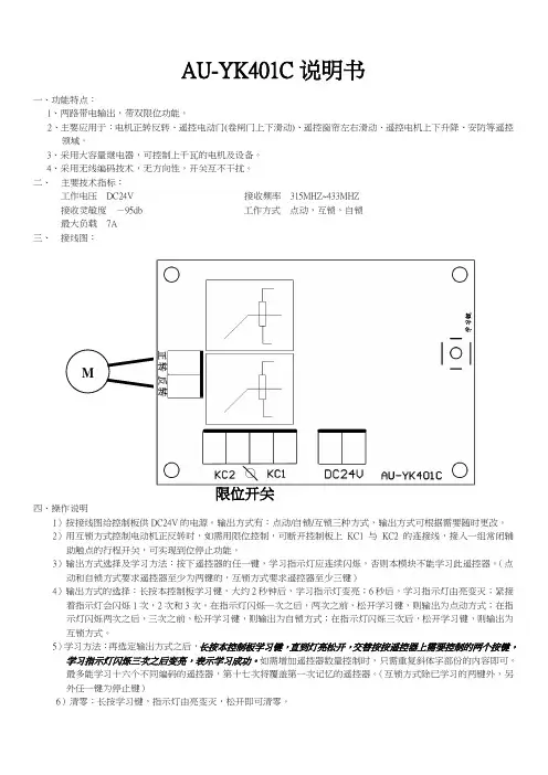
AU-YK401C说明书一、功能特点:1、两路带电输出,带双限位功能。
2、主要应用于:电机正转反转、遥控电动门(卷闸门上下滑动)、遥控窗帘左右滑动、遥控电机上下升降、安防等遥控领域。
3、采用大容量继电器,可控制上千瓦的电机及设备。
4、采用无线编码技术,无方向性,开关互不干扰。
二、主要技术指标:工作电压DC24V 接收频率315MHZ~433MHZ接收灵敏度-95db 工作方式点动,互锁,自锁最大负载7A三、接线图:限位开关四、操作说明1)按接线图给控制板供DC24V的电源。
输出方式有:点动/自锁/互锁三种方式,输出方式可根据需要随时更改。
2)用互锁方式控制电动机正反转时,如需用限位控制,可断开控制板上KC1 与KC2 的连接线,接入一组常闭辅助触点的行程开关,可实现到位停止功能。
3)输出方式选择及学习方法:按下遥控器的任一键,学习指示灯应连续闪烁,否则本模块不能学习此遥控器。
(点动和自锁方式要求遥控器至少为两键的,互锁方式要求遥控器至少三键)4)输出方式的选择:长按本控制板学习键,大约2秒钟后,学习指示灯变亮;6秒后,学习指示灯由亮变灭;紧接着指示灯会闪烁1次,2次和3次。
在指示灯闪烁一次之后,两次之前,松开学习键,则输出为点动方式;在指示灯闪烁两次之后,三次之前,松开学习键,则输出为自锁方式;在指示灯闪烁三次后,松开学习键,则输出为互锁方式。
5)学习方法:再选定输出方式之后,长按本控制板学习键,直到灯亮松开,交替按按遥控器上需要控制的两个按键,学习指示灯闪烁三次之后变亮,表示学习成功。
如需增加遥控器数量控制时,只需重复斜体字部份的内容即可。
最多能学习十六个不同编码的遥控器,第十七次将覆盖第一次记忆的遥控器。
(互锁方式除已学习的两键外,另外任一键为停止键)6)清零:长按学习键,指示灯由亮变灭,松开即可清零。
1设备级驱动和自定义模块说明编制:黄轶青审核:曹瑞峰 梅建华批准:刘国耀南京科远控制工程有限公司NANJING KEYUAN CONTROL ENGNEERING CO., LTD2001年12月目录1.不可调电动门(ACT15A3W:TVL_BT): (5)1.1模块原理 (5)1.2主要特性有: (5)1.3工作模式:(优先权由高到低) (7)1.4模块参数: (7)1.5不可调电动门在逻辑图中的表达方法如下例: (9)1.6如何组态参照组态演示文件. (10)2.点动门(ACT15A3W:TVL_DD): (11)2.1模块原理 (11)2.2主要特性有: (11)2.3工作模式:(优先权由高到低) (13)2.4模块参数: (13)2.5点动门在逻辑图中的表达方法如下例: (14)2.6如何组态参照组态演示文件. (14)3. 全开全关执行机构(ACT15A3W:TVL_AN): (15)3.1模块原理 (15)3.2模块参数: (15)3.3全开全关执行机构在逻辑图中的表达方法如下例: (16)3.4如何组态参照组态演示文件. (16)4.单位式设备(ACT15A3W:TVL_RS): (17)4.1模块功能 (17)4.2模块参数: (18)4.3单位式设备在逻辑图中的表达方法如下例: (18)4.4如何组态参照组态演示文件. (19)5. 标准电机(ACT15A3W:TMT_ST): (19)5.1模块功能 (19)5.2主要特性有: (20)5.3工作模式:(优先权由高到低) (21)5.4模块参数: (21)5.5标准电机在逻辑图中的表达方法如下例: (22)5.6如何组态参照组态演示文件. (23)6. 一带四设备模块(DIGACT:TCK_ST): (24)6.1模块功能 (24)6.2模块参数: (24)6.3一带四设备模块在逻辑图中的表达方法 (25)6.4如何组态参照组态演示文件. (26)7.一带八设备模块(DIGACT:TCKGF8A): (28)7.1模块功能: (28)7.2主要特性有: (28)7.3模块参数: (28)7.4一带八设备模块在逻辑图中的表达方法 (29)7.5如何组态参照组态演示文件. (30)8. 多功能软伺放(ACT15A3W:ANMMF): (31)8.1模块功能 (31)8.2主要特性有: (31)8.3工作模式 (32)8.4模块参数: (33)8.5模块选型: (37)8.6如何组态参照组态演示文件. (37)9.模拟量手操模块(ACTION:MANS): (38)9.1模块功能 (38)9.2主要特性有: (38)9.3工作模式: (39)9.4模块参数: (40)9.5模拟量手操站在逻辑图中的表达方法 (42)9.6如何组态参照组态演示文件. (42)10.二值优选模块(ACTION:OF2VOTE(FILENAME和ACTNAME)): (44)10.1模块功能 (44)10.2参数 (44)10.3二值优选模块在逻辑图中的表达方法如下例: (45)10.4如何组态参照组态演示文件. (45)11.自动冗余切换、故障集合及负荷率运算模块(ACTION:DIAG(FILENAME和ACTNAME)):4511.1模块功能 (45)11.2模块参数 (45)11.3如何组态参照组态演示文件. (45)12.十一回路首出原因模块(ACT15A3W:ETSST(FILENAME和ACTNAME)): (46)12.1模块功能 (46)12.2模块参数 (46)12.3在逻辑图中的表达方法 (46)12.4如何组态参照组态演示文件. (46)13.串级回路抗积分饱和模块(ACTION:SERCO (FILENAME和ACTNAME)): (47)13.1块功能说明 (47)13.2参数 (47)13.3在逻辑图中的表达方法 (47)13.4如何组态参照组态演示文件. (47)14. 两前馈协调模块(ACTION:NODISTB(FILENAME和ACTNAME)): (48)14.1模块原理该 (48)14.2参数 (48)14.3在逻辑图中的表达方法 (48)14.4如何组态参照组态演示文件. (48)15. 过热蒸汽流量补偿(ACTION:MATH(FILENAME)FL_OVER(ACTNAME)): (49)15.1模块原理 (49)15.2参数 (49)15.3如何组态参照组态演示文件. (49)16. 汽包水位补偿模块(ACTION:MATH(FILENAME)DLEL(ACTNAME)): (50)16.1模块原理 (50)16.2参数 (50)16.3如何组态参照组态演示文件. (50)17. 积分处理模块(ACTION:INTGDW2(FILENAME和ACTNAME)): (51)17.1模块功能 (51)17.2参数 (51)17.3在逻辑图中的表达方法 (51)17.4如何组态参照组态演示文件. (51)18.一带八同操处理模块(ACTION:TCON(FILENAME和ACTNAME) (52)18.1模块功能 (52)18.2参数 (52)18.3在逻辑图中的表达方法 (53)18.4如何组态参照组态演示文件. (53)19 一带十二同操+一带四同操处理(ACT15A3W:TCON3W(FILENAME和ACTNAME)) (54)19.1模块功能 (54)19.2参数 (54)19.3在逻辑图中的表达方法 (55)19.4如何组态参照组态演示文件. (55)20. 八路电量脉冲累积模块(ACTION:PLSTAT(FILENAME) STAT8(ACTNAME)) (56)20.1模块功能 (56)20.2参数 (56)20.3在逻辑图中的表达方法 (56)20.4如何组态参照组态演示文件. (56)21. 机炉协调控制模块(ACT15A3W:LMCC(FILENAME和ACTNAME)): (57)21.1模块功能 (57)21.2模块参数 (57)21.3如何组态参照组态演示文件. (58)22.单元机组煤粉炉燃料控制模块 (59)22.1模块功能 (59)22.2模块参数 (59)22.3如何组态参照组态演示文件. (60)23.给水泵一用一备汽包水位控制模块.............................................................................. 错误!未定义书签。
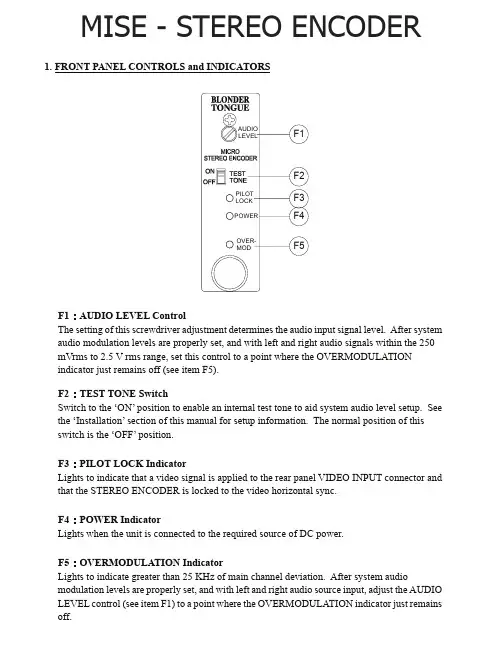
MISE - STEREO ENCODER 1. FRONT PANEL CONTROLS and INDICATORSF1:AUDIO LEVEL ControlThe setting of this screwdriver adjustment determines the audio input signal level. After system audio modulation levels are properly set, and with left and right audio signals within the 250 mVrms to 2.5 V rms range, set this control to a point where the OVERMODULATIONindicator just remains off (see item F5).F2:TEST TONE SwitchSwitch to the ‘ON’ position to enable an internal test tone to aid system audio level setup. See the ‘Installation’ section of this manual for setup information. The normal position of this switch is the ‘OFF’ position.F3:PILOT LOCK IndicatorLights to indicate that a video signal is applied to the rear panel VIDEO INPUT connector and that the STEREO ENCODER is locked to the video horizontal sync.F4:POWER IndicatorLights when the unit is connected to the required source of DC power.F5:OVERMODULATION IndicatorLights to indicate greater than 25 KHz of main channel deviation. After system audiomodulation levels are properly set, and with left and right audio source input, adjust the AUDIO LEVEL control (see item F1) to a point where the OVERMODULATION indicator just remains off.2. REAR PANEL CONNECTIONS / INTERNAL JUMPERSR1:VIDEO INPUT ConnectorThis is the baseband video input to the STEREO ENCODER which provides the encoder circuitry with the modulator horizontal sync information.The baseband video to the modulator must be ‘looped through’ this input using an external ‘F’ type Tee (T) connector.R2:COMPOSITE AUDIO OUT ConnectorThis is the unbalanced composite BTSC format stereo signal output. The output from this RCA phono receptacle must be connected to the AUDIO INPUT of the modulator.The connected modulator audio response must be set for ‘Flat’ (pre-emphasis defeated).R3:DC INPUT ConnectorThis 3-pin connector (Male) accepts the appropriate mating DC power cable. Observe proper orientation and wiring.R4:STEREO AUDIO INPUT ConnectorThis is the left and right audio source input connector that accept the stereo L/Rplug, 3.5mm3. INSTALLATION – AUDIO LEVEL SETTINGS METHOD 1:Connect the STEREO ENCODER, Audio/Video Modulator, compatible DC power source, video source signal and test equipment as shown.Using the connected spectrum analyzer, tune the aural carrier to the center of the screen.Spectrum Analyzer Settings. SPAN :100 KHz Res BW :1 KHz SWEEP :300 mSec. VBW :1 KHz3. Adjust the ‘Audio’ control on the front panel of the connected A/V modulator for a settingthat nulls the aural carrier. If more than one null is found, use the lowest audio gain setting that produces a null of the aural carrier.4. INSTALLATION – AUDIO LEVEL SETTING, continued4.Set the STEREO ENCODER TEST TONE switch to the ‘OFF’ position. Connect Left andRight audio source signals to the STEREO ENCODER.5.Set the ‘Audio LEVEL’ control on the STEREO ENCODER to a point where the‘OVERMODULATION’ indicator just remains off or flashes occasionally.The system audio levels are now properly set.Disconnect the test equipment.METHOD 2:(If a spectrum analyzer is not available)1.Connect the STEREO ENCODER, A/V modulator, compatible DC power source, andvideo source signal as shown on this page. Keep the ‘TEST TONE’ switch ‘OFF’ for this procedure.2.Connect a TV receiver (with MTS stereo capability) to the A/V modulator. Tune the TVreceiver to the same channel as the modulator output.NOTE:Make certain that the audio response of the A/V modulator is set for ‘FLAT’ (pre-emphasis defeated).3.Connect the audio source signal (not a tone) to either the LEFT or the RIGHT Audio Inputof the STEREO ENCODER.4.Set the ‘Audio LEVEL’ control on the STEREO ENCODER to a point where the‘OVERMODULATION’ indicator just remains off or flashes occasionally.5.While monitoring the opposite audio channel from the TV receiver audio output, set the‘Audio’ level control on the A/V modulator for a maximum (stereo) separation condition.5. SPECIFICATIONSAUDIO INPUTInput Impedance:20K Ohms unbalanced.Input Level:250 mVrms ~ 2.5 Vrms, AdjustableVIDEO INPUTInput Impedance:10 Kohm min.Input Level Range:0.5 Vp-p to 2 Vp-pCOMPOSITE OUTPUTOutput Impedance:100 OhmsOutput Level: 1.1 Vp-p @100% modulationSTEREO PERFORMANCEStereo Separation:20 dB.Total Harmonic Distortion:0.25% Max.S/N Ratio:65 dB. Min.Frequency Response:± 1 dB @50 Hz to 12 KHz.Spurious Subcarrier:-50 dBc typ.TEST TONEFrequency:10.396 KHz ±50 Hz.Amplitude:0.5 Vp-p ± 10%GENERALDC Power Input:+12V ±5% @ 200 mAOperating Temperature Range:0℃ to + 50℃ ambient.Size: 2.6 (L) × 8.0 (H) × 23.4 (W) cmWeight:0.33 kgOne Jake Brown RoadOld Bridge, NJ 08857-1000 USA(800) 523-6049 • (732) 679-4000 • FAX: (732) 679-4353。
产品使用手册315M超再生带解码四路无线接收模块普通桃木四键遥控器.四键遥控器和超再生固定码接收模块可以组成四路无线发射接收电路,遥控器的四位数据码对应模块的四路输出,可以方便的组成无线遥控发射接收电路,该产品广泛适用于广大电子爱好者的家庭、工业遥控类电子产品的设计和开发,可很好的作为单片机的信号输入源,特别适合大中院校学生电子电路设计、毕业设计中的遥控电路部分,可与单片对接,或加一级放大驱动继电器或小型直流电机。
接收板有自锁、非锁、互锁三种型号。
非锁、自锁、互锁三种工作方式说明非锁型SC2272-M4输出又称点动输出,数据脚输出的电平是瞬时的而且和发射端是否发射相对应,可以用于类似点动的控制,有遥控信号时数据脚是高电平,遥控信号消失时数据脚立即恢复为低电平,适用于如电动门、电动门锁、与单片机对接等只需要一个高电平的电路等电路等。
自锁型SC2272-T4输出的数据脚能实现触发翻转工作逻辑,数据只要成功接收就能一直保持对应的电平状态,直到下次遥控数据发生变化时改变。
自锁型四路相互独立互不影响,可同时遥控四路,如灯具的控制等。
互锁型SC2272-L4输出就是任意一路收到信号则该路就能一直保持对应的高电平状态,接收到任意其它路的数据则恢复到原始状态,四路互锁只能有一路接通,实际应用如电风扇档位开关电路等。
接收板主要参数工作频率:315M工作电压:DC5V工作电流:≤3mA(5.0VDC)工作原理:超再生调制方式:ASK编码芯片:SC2272(PT2272、PT2294),芯片兼容灵敏度:优于-105dBm(50Ω)输出信号:非锁型(PT2272-M4)遥控距离:20~50米以上(开阔地)接收模块的七根引脚分别为D3、D2、D1、D0、GND、VT、VCC,其中VCC为DC5V的供电端,GND为接地端,VT端为解码有效输出端,只要发射器的数据码有输出,VT都能同步输出高电平;D3、D2、D1、D0是2262解码芯片的四位数据输出端,有信号时能输出5V左右的高电平,驱动电流约2mA,与发射器的四位数据码输出一一对应。
Giant204四通道称重模块用户手册 V1.0目录1 技术支持 (3)2 产品介绍 (4)3 技术参数 (5)4 外形尺寸,电气连接以及选型 (6)4.1 外形尺寸 (6)4.2 电气连接与说明 (6)4.2.1 称重传感器连接 (7)4.2.2 指示灯 (8)4.2.3 通信接口RS232/RS485 (8)4.3 选型 (8)5 显示与按键 (9)6 功能与设置 (10)6.1 主界面显示与功能 (11)6.1.1 相关指令 (12)6.2功能菜单 (15)6.2.1 相关指令 (16)6.3校准菜单 (21)6.3.1 校准方式选择菜单 (21)6.3.2 实物校准菜单 (22)6.3.3 数字校准菜单 (24)6.3.4 相关指令 (25)6.4 参数保存菜单 (27)6.4.1相关指令 (27)6.5 显示设置菜单 (28)6.5.1相关指令 (28)6.6 通信设置菜单 (29)6.6.1 相关指令 (30)7 MODBUS通讯协议 (33)8用户设置软件 (40)8.1 软件安装与启动 (40)9 附件 (41)9.1 仪表显示的错误代码 (41)9.2 基本术语 (41)9.3 标准ASCII码 (42)1 技术支持感谢您选择并使用大连哲勤科技有限公司产品,此用户手册协助您了解并正确使用设备。
如需订购产品、技术支持、以及产品信息反馈,请通过以下方式联系我们。
请在联系时附注设备的购买时间,购买方式,联系人信息,地址以及电话等相关信息,便于我们为您服务。
网址E-Mail**************电话+86-411-66831953, 4000-511-521传真+86-411-82388125版本控制2 产品介绍Giant204四通道称重变送器是面向工业控制领域的重量变送器,集四个高速称重通道,RS485和RS232通信接口于一体(Modbus-RTU通信协议),同时进行四个重量的独立并行高速检测。
AU-YK04解码接收模块规格说明书产品型号:AU-YK04产品名称:5伏高频超再生四路解码接收模块一、技术参数工作电压(V):DC5V静态电流(mA): 4.5MA调制方式:调幅(OOK)工作温度: -10℃~+70℃接收灵敏度(dBm):-105DB工作频率(MHz):315、433.92MHz(266-433MHZ频率段可任选)编码方式:焊盘编码(固定码)工作方式:M4(点动:按住不松手就输出,一松手就停止输出)、L4(互锁:四路同时只能有一路输出)、T4(自锁:四路相互独立输出、互不影响,按一下输出再按一下停止输出)尺寸(LWH):40*22*7mm二、产品特点:超再生接收模块采用LC振荡电路,内含放大整形,输出的数据信号为解码后的高电平信号,使用极为方便,并且价格低廉,所以被广泛使用。
带四路解码输出(同时也可改为六路点动或互锁输出),使用方便;频点调试容易,供货周期短;产品质量一致性好,性价比高。
接收模块有较宽的接收带宽,一般为±10MHz,出厂时一般调在315MHz或433.92MHZ(如有特殊要求可调整频率,频率的调整范围为266MHz~433MHz。
)。
接收模块一般采用DC5V供电,如有特殊要求可调整电压范围。
三、脚位及使用说明:接收模块一共有八个外部接口,上面有英文表示。
“5V”表示接电源正极,“ D0、D1、D2、D3”表示输出,“GND”表示接电源负极,“ANT”表示接天线端。
使用前要接上50欧姆1/4波长的天线,并且天线应该是直的,以达到最佳的接收效果,波长=光速/频率。
四、应用环境(应用领域)无线遥控开关、遥控插座、数据传输、遥控玩具、防盗报警主机、车库门、卷闸门、道闸门、伸缩门等门控业及其遥控音响领域等。
五、自选配件与公司发射系列、遥控器系列产品配套使用。
六、备注VCC电压要与模块工作电压一致,且要做好电源滤波;天线对模块的接收效果影响很大,最好接1/4波长的天线,一般采用50欧姆单芯导线,天线的长度315M的约为23cm,433M的约为17cm;天线位置对模块接收效果亦有影响,安装时,天线尽可能伸直,远离屏蔽体,高压,及干扰源的地方;使用时接收频率、解码方式应与发射匹配。
KINTEX UltraScale开发平台用户手册ACKU040核心板2 / 24芯驿电子科技(上海)有限公司文档版本控制文档版本修改内容记录REV1.0创建文档目录文档版本控制 (2)一、ACKU040核心板 (4)(一)简介 (4)(二)FPGA芯片 (5)(三)DDR4 DRAM (5)(四)QSPI Flash (10)(五)时钟配置 (11)(六)LED灯 (12)(七)电源 (12)(八)结构图 (14)(九)连接器管脚定义 (14)3 / 244 / 24芯驿电子科技(上海)有限公司一、 ACKU040核心板(一) 简介ACKU040(核心板型号,下同)核心板,FPGA 芯片是基于XILINX 公司的XC7K325系列的XCKU040-2FFVA1156I 。
核心板使用了4片Micron 的1GB 的DDR4芯片MT40A512M16LY-062EIT,总的容量达4GB 。
另外核心板上也集成了2片128MBit 大小的QSPI FLASH ,用于启动存储配置和系统文件。
这款核心板的6个板对板连接器扩展出了359个IO ,其中BANK64和BANK65的104个IO 的电平是3.3V ,其它BANK 的IO 都是1.8V 。
另外核心板也扩展出了20对高速收发器GTH 接口。
对于需要大量IO 的用户,此核心板将是不错的选择。
而且IO连接部分,FPGA 芯片到接口之间走线做了等长和差分处理,并且核心板尺寸仅为80*60(mm ),对于二次开发来说,非常适合。
ACKU040核心板正面图5 / 24(二) FPGA 芯片核心板使用的是Xilinx 公司的KINTEX UltraSacale 芯片,型号为XCKU040-2FFVA1156I 。
速度等级为2,温度等级为工业级。
此型号为FFVA1156封装,1156个引脚,引脚间距为1.0mm 。
Xilinx KINTEX UltraSacale 的芯片命名规则如下图1-2-1所示:图1-2-1 KINTEX UltraSacale FPGA 型号命名规则定义其中FPGA 芯片XCKU040的主要参数如下所示:名称具体参数 逻辑单元Logic Cells 530,250 查找表(CLB LUTs) 242,400 触发器(CLB flip-flops) 484,800 Block RAM (Mb )大小 21.1 DSP 处理单元(DSP Slices )1,920 PCIe Gen3 x8 3GTH Transceiver20个,16.3Gb/s max速度等级 -2 温度等级工业级(三) DDR4 DRAM核心板上配有四片Micron(美光)的1GB 的DDR4芯片,型号为MT40A512M16LY-062EIT 。
---------------------------------------------------------------------------------------------------------------------------------------------------User Manual RX-4MHCS433.92 MHz OOK (AM) Receiver - 4 output channelsDescription Array The mono-stable and bi-stable mode and the opencollector outputs make it ideal for telecontrol ofappliances like gate door openers,burglar alarmsystems and wherever it’s requested encoding ofradio link. Furthermore it’s able to learn the code ofHCS transmitters.Compatible with AUREL keyfobs:HCS-TX-1/2/3(OVO),TX1/2/3-HCS-433(HCS),TX-2/4/6 M-HCS, TX-12 CH.Connection Pin-Out:2) GND3) Antenna7) GND8) Test Point – RX analog output9) Programming push button10) Ch1 output - Open collector (Triggered by pushing button 1 in the keyfob)11) Ch2 output- Open collector (Triggered by pushing button 2 in the keyfob)12) Ch3 output- Open collector (Triggered by pushing button 3 in the keyfob)13) Ch4 output- Open collector (Triggered by pushing button 4 in the keyfob)14) LED output – Connected to anode of LED15) Vcc (+5Volt)Technical features are subject to change without notice. AUREL S.p.A. does not assume responsibilities for any damages caused by the device’s misuse.------------------------------------------------------------------------------------------------------------------------------------------------------------------------------------------------------------------------------------------------------------------------------------------------------------------------User ManualHow to get startedThe voltage supply to the module (pin 15) shall be 5Vdc. Pin 9 shall be connected to the push button for programming the receiver, pin 14 shall be connected to the anode of LED to control that programming has been carried out (output current is internally limited to around 20 mA by a 180 ohm resistor). External antenna shall be connected, by utilizing for example a piece of wire 17 cm long and a surrounding widespread ground plane.Every output of RX-4MHCS is driven by a transistor in open collector configuration, able to bear max current of 100 mA. In stand-by mode transistor is cut off while when triggered is in saturation region. Output can be programmed to work in mono-stable or bi-stable mode, every one independent from the others.In mono-stable mode output is active for all the time the corresponding push button is pressed in the keyfob, releasing the button output switches off.In bi-stable mode output switches its state every time the corresponding push button is pressed in the keyfob (from active to inactive and vice versa). The two operative modes are independent each other, that means it’s possible to program some outputs as mono-stable and some others as bi-stable.If an inductive load is connected to the output (i.e. a relay) it’s necessary to prevent voltage transients by putting a diode in parallel to the inductive load. LED anode shall be connected towards the output of the module.In order to enable the receiver to activate its outputs it’s necessary to store in the RX-4MHCS the keyfobs codes. To carry out this operation it’s necessary to approach the keyfob to the receiver. By pressing a push button (it doesn’t matter which one) of the keyfob during the auto-learning phase, the receiver RX-4MHCS recognises the button pressed and all other channels automatically.Only the keyfobs with HCS encoder shall be recognised by the receiver RX-4MHCS. Keyfobs not programmed or programmed with manufacturer code different from the one used by AUREL would not be recognised.Based on reasonable demand, Aurel is willing to program the receiver RX-4MHCS with specific manufacturer code indicated by the customer.Ground planeThe circuit must be double layer. Ground plane must surround at the best the welding area of the receiver. For further info please refer to the user manuals of AUREL’s receivers.Ca pa c ità di disa c c oppia mento L inea 50 ohm +5VConnessi oneA nt ennaTechnical features are subject to change without notice. AUREL S.p.A. does not assume responsibilities for any damages caused by the device’s misuse. ------------------------------------------------------------------------------------------------------------------------------------------------------------------------------------------------------------------------------------------------------------------------------------------------------------------------User Manual ProgrammingHow to erase the memoryIn order to reset the RX-4MHCS, press the push button connected to pin 9 and release it when LED starts blinking. Now press again the push button and hold it pressed for around 5 seconds until it switches off again. As you release the push button the LED blinks 5 times indicating that memory has been erased.After carrying out the reset, no HCS encoded keyfob shall be recognised and all outputs shall be set up in mono-stable mode.Auto-learning procedureBy pressing and soon releasing the programming push button the auto-learning procedure is initiated. LED blinks quickly for 10 seconds: for this time long, every time a push button of a keyfob, located near the RX-4MHCS, is pressed, such keyfob would be learnt. Programming of RX-4MHCS is confirmed by LED with steady red light, afterwards it switches off.When programmed all push buttons of the keyfob are learnt and each of them activate the corresponding output. Outputs will be mono-stable.It’s possible to repeat this procedure to allow the receiver RX-4MHCS to learn up to 10 keyfobs.Bi-stable mode programmingIn order to get the output bi-stable, press and release the push button. LED blinks quickly for 10 seconds: for this time long it must be pressed the push button again. LED turns from blinking to steady light. In the next 10 seconds it’s possible to press the button corresponding to the output to make bi-stable, getting the keyfob close to RX-4MHCS. The receiver shows that operations has been successfully carried out by 3 blinks of LED.To turn back to mono-stable mode repeat the above described procedure; in this case LED blinks just twice to indicate the operation was successful.Change of output functionality mode can be executed only after the receiver learns the keyfob code.Technical features are subject to change without notice. AUREL S.p.A. does not assume responsibilities for any damages caused by the device’s misuse.---------------------------------------------------------------------------------------------------------------------------------------------------------------------。
auky功放说明书说明书概述本说明书为UKY功放的详细说明,介绍了功放的功能、使用方法、技术参数及维护注意事项等内容。
请仔细阅读本说明书,并按照要求正确使用和维护功放,以保证其正常工作和使用寿命。
一、功能介绍1.功率输出:UKY功放采用先进的功率放大技术,能够提供高质量的音频输出,输出功率可达到XW,能满足不同场合的需求。
2.输入接口:功放配备多种输入接口,包括RCA接口、XLR接口和TRS接口,可与不同类型的音频设备相连接,实现信号输入的多样性。
3.输出接口:功放提供扬声器输出接口,可连接多个扬声器,并可进行灵活的音量调节和平衡控制,以满足各类音频输出要求。
4.噪音控制:功放采用先进的噪音控制技术,能有效降低输出过程中的噪音干扰,提供清晰而优质的音频输出效果。
5.保护机制:功放配备多种保护机制,包括过载保护、过热保护和短路保护等,能有效保护功放和连接设备不受损害,并延长其使用寿命。
二、使用方法1.连接电源:将功放正确连接到电源插座,确保电源电压稳定,电源指示灯亮起。
2.信号输入:通过选择合适的输入接口,将音频信号源与功放相连接,确保信号源正常工作,选择合适的输入通道,并调节音量控制旋钮。
3.扬声器连接:将扬声器通过扬声器输出接口与功放相连接,确保连接稳固无松动,并根据需要进行平衡调节。
4.电源开关控制:按下电源开关,功放开始工作,此时可根据需要调整音量大小和平衡。
三、技术参数1.输出功率:XW2.频率响应范围:XXHz-XXkHz3.输入阻抗:XXΩ4.输入灵敏度:XXdB5.扬声器加载阻抗:XXΩ6.信噪比:XXdB7.总谐波失真:小于X%8.工作电压:XXXV9. 产品尺寸:XXX(宽)*XXX(高)*XXX(深)mm10. 产品重量:XXkg四、维护注意事项1.使用环境:避免在潮湿、高温、低温及多尘的环境中使用功放,以免影响其性能和使用寿命。
2.清洁保养:定期清洁功放的表面和散热孔,确保内部散热正常,并避免进入尘埃和异物。
AU-YK04解码接收模块规格说明书
产品型号:AU-YK04
产品名称:5伏高频超再生四路解码接收模块
一、技术参数
工作电压(V):DC5V
静态电流(mA): 4.5MA
调制方式:调幅(OOK)
工作温度: -10℃~+70℃
接收灵敏度(dBm):-105DB
工作频率(MHz):315、433.92MHz(266-433MHZ频率段可任选)
编码方式:焊盘编码(固定码)
工作方式:M4(点动:按住不松手就输出,一松手就停止输出)、L4(互锁:四路同时只能有一路输出)、T4(自锁:四路相互独立输出、互不影响,按一下输出再按一下停止输出)
尺寸(LWH):40*22*7mm
二、产品特点:
超再生接收模块采用LC振荡电路,内含放大整形,输出的数据信号为解码后的高电平信号,使用极为方便,并且价格低廉,所以被广泛使用。
带四路解码输出(同时也可改为六路点动或互锁输出),使用方便;频点调试容易,供货周期短;产品质量一致性好,性价比高。
接收模块有较宽的接收带宽,一般为±10MHz,出厂时一般调在315MHz或433.92MHZ(如有特殊要求可调整频率,频率的调整范围为266MHz~433MHz。
)。
接收模块一般采用DC5V供电,如有特殊要求可调整电压范围。
三、脚位及使用说明:
接收模块一共有八个外部接口,上面有英文表示。
“5V”表示接电源正极,“ D0、D1、D2、D3”表示输出,“GND”表示接电源负极,“ANT”表示接天线端。
使用前要接上50欧姆1/4波长的天线,并且天线应该是直的,以达到最佳的接收效果,波长=光速/频率。
四、应用环境(应用领域)
无线遥控开关、遥控插座、数据传输、遥控玩具、防盗报警主机、车库门、卷闸门、道闸门、伸缩门等门控业及其遥控音响领域等。
五、自选配件
与公司发射系列、遥控器系列产品配套使用。
六、备注
VCC电压要与模块工作电压一致,且要做好电源滤波;
天线对模块的接收效果影响很大,最好接1/4波长的天线,一般采用50欧姆单芯导线,天线的长度315M的约为23cm,433M的约为17cm;
天线位置对模块接收效果亦有影响,安装时,天线尽可能伸直,远离屏蔽体,高压,及干扰源的地方;
使用时接收频率、解码方式应与发射匹配。