CANopen devds402_对象字典设计(德国)
- 格式:pdf
- 大小:1.09 MB
- 文档页数:7
CANopen对象字典生成办法发布时间:2013-09-25 来源:中国自动化网类型:解决方案1081人浏览关键字:CANopen对象字典生成器导读:本文在阐述CANopen对象字典的概念与结构的基础之上,结合生成对象字典常用方法的不足,引出一种可快速可靠创建与修改对象字典的对象字典生成器ODBuilder,不仅有效减少编辑对象字典的时间,而且最大限度地避免工程师手工编辑对象字典的错误出现,为CANopen设备参数设置提供有力可靠的解决方案。
摘要:本文在阐述CANopen对象字典的概念与结构的基础之上,结合生成对象字典常用方法的不足,引出一种可快速可靠创建与修改对象字典的对象字典生成器ODBuilder,不仅有效减少编辑对象字典的时间,而且最大限度地避免工程师手工编辑对象字典的错误出现,为CANopen设备参数设置提供有力可靠的解决方案。
关键词:CANopen,对象字典,生成器,ODBuilder,EDS文件Abstract:In this paper, on the introduction of the concept and structure of the CANo pen object dictionary,c ombined with the shortage of common methods of generat ing object dictionary, l ead to a object dictionary generator-ODBuilde r,which is quick ly and reliabl y create and modify the CANopen object diction ary. T his tool not only effectively reduce the time of editing object dict ionary, but significantly minimize the occurrence of error of manual ly edit ing the object dictionary, and provid e a robust and reliable solutions for th e parameter Settings of CANopen equipment.Key words:CANopen,Object dictionary,generator,ODBuilder,EDS File引言CANopen协议是一种基于控制器局域网(CAN)的应用层协议,该协议具有实时高效、组网灵活和产品兼容性高等优势,CANopen协议在国内越来越受到青睐,其应用领域也越来越多广泛,不仅应用于过程与生产自动化等领域,还涉及到医疗、铁路、军事、太阳能等等领域。

基于分布式运动控制系统 CANopen 简介基于分布式运动控制系统 CANopen 简介徐国平 运动控制产品经理深圳市泰科智能伺服技术有限公司Techsoft motion (Shenzhen) technology Ltd.2009 年 7 月 8 日 © Techsoft深圳市泰科智能伺服技术有限公司概述基于分布式运动控制系统 CANopen 简介◇ 分布式控制与集中式运动控制系统的比较 ◇ CAN物理层 ◇ CANopen协议 ◇ 驱动器与运动控制设备概述 ◇ 多轴同步协调运动 ◇ IDMxxx(CAN/CANopen)系列全数字通用伺服驱动器2009 年 7 月 8 日 © Techsoft深圳市泰科智能伺服技术有限公司1基于分布式运动控制系统 CANopen 简介分布式与集中式运动控制系统的比较◇ 集中式运动控制系统• 多轴运动控制卡或控制器 • 位置/速度/转矩伺服驱动器或放大器 • 电机2009 年 7 月 8 日 © Techsoft深圳市泰科智能伺服技术有限公司2集中式运动控制系统组成部分◇ 控制器• PC运动控制卡 • 独立式运动控制器 • +/- 10V命令信号◇ 驱动器或放大器• 位置/速度/转矩模式 • 模拟量或数字量驱动器◇电 机• 旋转或直线伺服电机 • 步进、有刷、无刷伺服电机基于分布式运动控制系统 CANopen 简介2009 年 7 月 8 日 © Techsoft深圳市泰科智能伺服技术有限公司3集中式运动控制系统的缺点◇ 控制轴数相对性能的限制性 ◇ 控制器轴数相对所需应用轴数的限制性 ◇ 模拟量命令信号的限制性 ◇ 驱动器或放大器诊断的限制性 ◇ 电机反馈到驱动器与控制器都必需接线 ◇ 接线复杂、成本高、可靠性降低基于分布式运动控制系统 CANopen 简介2009 年 7 月 8 日 © Techsoft深圳市泰科智能伺服技术有限公司4分布式运动控制系统◇ 分布式运动控制系统主控制器 驱动器 电机基于分布式运动控制系统 CANopen 简介2009 年 7 月 8 日 © Techsoft深圳市泰科智能伺服技术有限公司5分布式运动控制系统的组成部分◇ 控制器• 计算机 • 独立式控制器 • 数字网络 (设备总线,现场总线,网络)◇ 驱动器• 位置,速度,转矩模式 • 带网络接口的数字伺服驱动器◇ 电机• 旋转或直线伺服电机 • 步进、有刷、无刷伺服电机基于分布式运动控制系统 CANopen 简介2009 年 7 月 8 日 © Techsoft深圳市泰科智能伺服技术有限公司6分布式运动控制系统的优势◇ 主控制器选择简单 ◇ 全数字命令信号 ◇ 全驱动器诊断 ◇ 仅电机到驱动器之间反馈必须接线 ◇ 整体体积减小 ◇ 整体接线减少• 降低成本 • 降低复杂性 • 提高可靠性◇ 减少系统成本• 驱动器成本增加 • 省掉了多轴运动控制器成本 • 减少了接线成本2009 年 7 月 8 日 © Techsoft基于分布式运动控制系统 CANopen 简介深圳市泰科智能伺服技术有限公司7CAN 物理层基于分布式运动控制系统 CANopen 简介◇ CAN(Controller Area Network),由 BOSCH 公司原创,ISO-11898 标准 ◇ 1Mbit/s 传输速度时距离可达 30 米 ◇ 多路访问冲突侦测+非破坏性解决 ◇ CAN2.0A(11 位标识符)或 CAN2.0B(29 位标识符) ◇ 冲击噪声免疫 ◇ 总线结构(3 线) ◇ 硬件自动检测与处理错误2009 年 7 月 8 日 © Techsoft深圳市泰科智能伺服技术有限公司8CAN 物理层◇ 数据帧(CAN Message)• SOF: 帧起始域 • Arbitration Field: 仲裁域Identifier: 标识符 RTR • Control Field: 控制域 • Data Field: 数据域 • CRC Field: 循环沉余校验域 • ACK Field: 应答域 • EOF Field: 帧结束域基于分布式运动控制系统 CANopen 简介2009 年 7 月 8 日 © Techsoft深圳市泰科智能伺服技术有限公司9。
canopen 字典使用方法CanOpen 字典的使用方法引言:CanOpen 是一种用于工业自动化领域的通信协议,它基于 CAN 总线,并使用字典来组织和描述设备的功能和参数。
本文将介绍CanOpen 字典的使用方法,帮助读者更好地理解和应用 CanOpen 协议。
一、CanOpen 字典的概述CanOpen 字典是CanOpen 协议中的重要组成部分,它定义了设备的功能和参数,使得CanOpen 设备之间可以进行有效的通信。
字典由一系列的对象字典和子字典组成,每个对象字典包含一个或多个对象,每个对象有唯一的标识符和属性,用于描述设备的功能和参数。
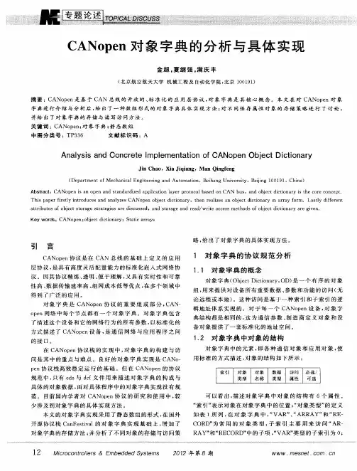
二、CanOpen 字典的结构CanOpen 字典采用树状结构组织,由对象字典和子字典构成。
对象字典是字典的最基本单位,它包含了设备的功能和参数信息。
子字典是对象字典的集合,用于组织和分类对象字典。
通过对象字典的索引和子字典的标识符,可以方便地定位和访问设备的功能和参数。
三、CanOpen 字典的使用方法1. 查找对象字典要查找对象字典,首先需要知道设备的字典索引和子字典标识符。
然后,按照索引和标识符,可以在CanOpen 字典中找到相应的对象字典。
可以使用CanOpen 设备的配置工具或者CanOpen 字典编辑器来查找对象字典。
2. 读取对象字典读取对象字典的方法取决于CanOpen 设备的通信接口和协议。
通常,可以通过发送特定的CanOpen 消息来读取对象字典。
消息中包含了读取对象的索引和标识符,设备接收到消息后,会返回相应的对象值。
3. 写入对象字典写入对象字典和读取对象字典类似,也需要发送特定的CanOpen 消息。
消息中包含了写入对象的索引、标识符和数值。
设备接收到消息后,会将数值写入相应的对象字典中。
4. 配置对象字典CanOpen 字典中的对象可以通过配置来实现特定的功能和参数设置。
配置对象字典通常需要发送一系列的CanOpen 消息,包含了配置信息和指令。
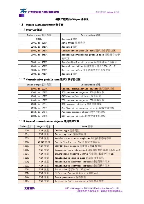
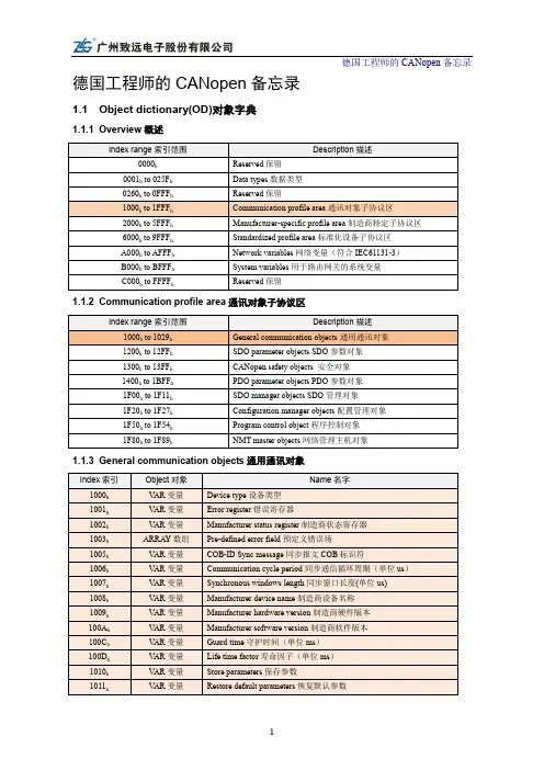
德国工程师的CANopen备忘录1.1 Object dictionary(OD)对象字典1.1.1 Overview概述1.1.2 Communication profile area通讯对象子协议区1.1.3 General communication objects通用通讯对象1.2 Pre-defined CAN-IDs预定义CAN标识符1.3 Network management(NMT)网络管理1.4 Service data object(SDO)服务数据对象1.4.1 communication principle(通讯原则)1.4.2 Expedited SDO protocol(快速SDO协议)1.4.3 Normal SDO protocol(普通SDO协议)1. 下载协议download protocol2. 上传协议upload protocol1.5 Process data object(PDO)过程数据对象RPDO通讯参数1400h to 15FF h映射参数1600h to 17FF h数据存放为2000h之后厂商自定义TPDO通讯参数1800h to 19FF h映射参数1A00h to 1BFF h数据存放为2000h之后厂商自定义CAN transmission( CAN发送报文)TPDO1(CAN-ID see 1800h 01h) Data field:数据域1.6 Special protocols(特殊协议)1.6.1 同步协议Sync protocol1.6.2 Time-stamp protocol(时间戳协议)1.6.3 Emergency protocol(紧急报文协议)1.6.4 Emergency error codes(紧急报文错误代码)。
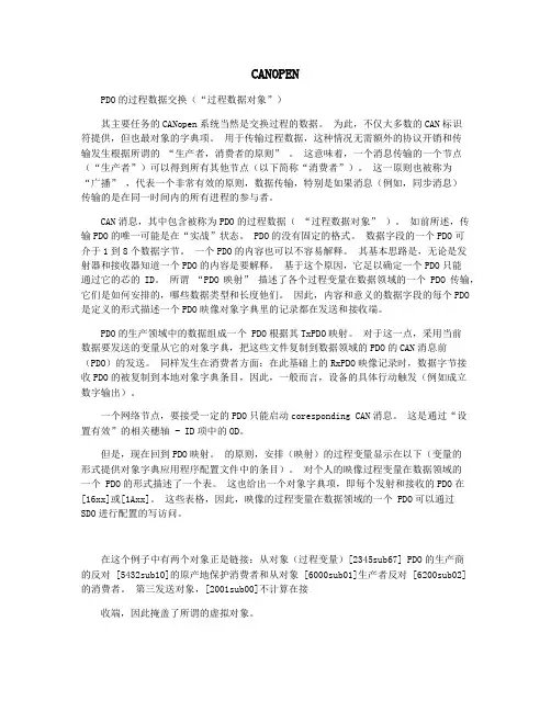
CANOPENPDO的过程数据交换(“过程数据对象”)其主要任务的CANopen系统当然是交换过程的数据。
为此,不仅大多数的CAN标识符提供,但也最对象的字典项。
用于传输过程数据,这种情况无需额外的协议开销和传输发生根据所谓的“生产者,消费者的原则” 。
这意味着,一个消息传输的一个节点(“生产者”)可以得到所有其他节点(以下简称“消费者”)。
这一原则也被称为“广播” ,代表一个非常有效的原则,数据传输,特别是如果消息(例如,同步消息)传输的是在同一时间内的所有进程的参与者。
CAN消息,其中包含被称为PDO的过程数据(“过程数据对象” )。
如前所述,传输PDO的唯一可能是在“实战”状态。
PDO的没有固定的格式。
数据字段的一个PDO可介于1到8个数据字节。
一个PDO的内容也可以不容易解释。
其基本思路是,无论是发射器和接收器知道一个PDO的内容是要解释。
基于这个原因,它足以确定一个PDO只能通过它的芯的ID。
所谓“PDO映射” 描述了各个过程变量在数据领域的一个PDO传输,它们是如何安排的,哪些数据类型和长度他们。
因此,内容和意义的数据字段的每个PDO 是定义的形式描述一个PDO映像对象字典里的记录都在发送和接收端。
PDO的生产领域中的数据组成一个 PDO根据其TxPDO映射。
对于这一点,采用当前数据要发送的变量从它的对象字典,把这些文件复制到数据领域的PDO的CAN消息前(PDO)的发送。
同样发生在消费者方面:在此基础上的RxPDO映像记录时,数据字节接收PDO的被复制到本地对象字典条目,因此,一般而言,设备的具体行动触发(例如成立数字输出)。
一个网络节点,要接受一定的PDO只能启动coresponding CAN消息。
这是通过“设置有效”的相关穗轴 - ID项中的OD。
但是,现在回到PDO映射。
的原则,安排(映射)的过程变量显示在以下(变量的形式提供对象字典应用程序配置文件中的条目)。
对个人的映像过程变量在数据领域的一个 PDO的形式描述了一个表。
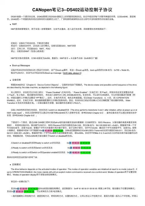
CANopen笔记3--DS402运动控制⼦协议 DS301就是⼀个通讯协议栈,DS402是建⽴在DS301基础之上的伺服类控制协议。
协议中规定好每个对象字典值的作⽤,⽐如0x6040,是控制字。
DS402把⼀个伺服控制系统应该具有的功能都定义好了,⼚家和使⽤者按照协议定义即可开发和使⽤符合标准的设备。
NMT NMT是⽹络管理报⽂,⽤于实现⼀些管理操作,⽐如节点重启、进⼊运⾏状态等,⽹络管理状态转换图如下: 初始化:设备处于启动状态,不能进⾏通信 预运⾏:设备启动完毕,还未进⼊运⾏模式。
设备仅回复SDO、NMT消息 运⾏:正常⼯作,可回复SDO、NMT、PDO 停⽌:仅能发送NMT(包括⼼跳消息) NMT报⽂格式很简单,COB-ID固定为0x000,数据为:NMT命令 + 从设备节点ID(0x00表⽰⼴播)Boot-up Messages 设备开机启动完成初始化进⼊预运⾏状态时,会产⽣boot-up事件,发送⼀条boot-up消息。
boot-up消息的COB-ID为:0x700 + Node ID。
假设节点ID为1,则该节点开机后会发送boot-up message(0x00 data, always 0)设备控制 根据DS402协议(Chapter 6:Device Control Objects),设备的状态由下图描述。
The device states and possible control sequence of the drive are described by the state machine, as depicted in the following figure: 如上图所⽰,状态机可以分成三部分:“ Power Disabled” (主电关闭)、“ Power Enabled”(主电打开)和“Fault”。
所有状态在发⽣报警后均进⼊“Fault”。
在上电后,驱动器完成初始化,然后进⼊SWITCH_ON_DISABLED状态。
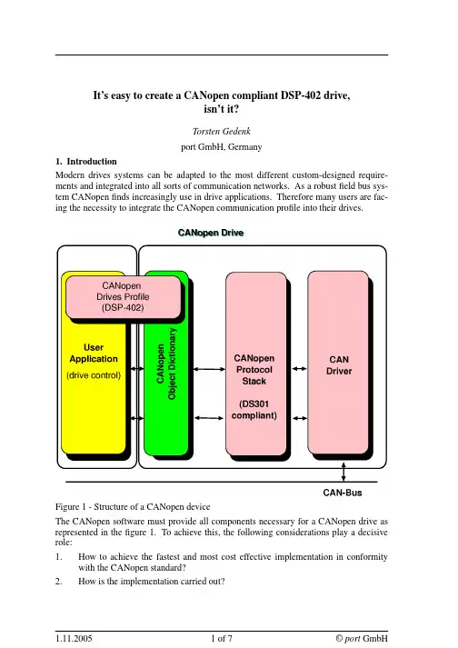
It’s easy to create a CANopen compliant DSP-402 drive,isn’t it?Torsten Gedenkport GmbH, Germany1. IntroductionModern drives systems can be adapted to the most different custom-designed require-ments and integrated into all sorts of communication networks. As a robust field bus sys-tem CANopen finds increasingly use in drive applications. Therefore many users are fac-ing the necessity to integrate the CANopen communication profile into their drives.Figure 1 - Structure of a CANopen deviceThe CANopen software must provide all components necessary for a CANopen drive as represented in the figure 1.To achieve this, the following considerations play a decisive role:1. How to achieve the fastest and most cost effective implementation in conformitywith the CANopen standard?2. How is the implementation carried out?3. Which software tools are available?4. Which of these are, in addition, useful?This article describes how a CANopen drive can be developed successfully in shortest time with the aid of software tools.2. Components of a CANopen driveThe CiA has published different standards for the communication in a CANopen net-work. The available CANopen services are defined in the communication profile DS-301. Special drive functions with their parameters are defined in the "Device profiles Drives and Motion Control" DSP-402.The DSP-402 defines the behavior of a drive at the start, the configuration and the execution of motion sequences by a state machine.A CANopen drive can be divided into following parts:•drive application•communication stack and special drive profile in conformity with the standards DS-301 and DSP-402.•object dictionary•CAN driver interfaceThe drive application is not CANopen specific and therefore shall not be examined in detail. The communication interface and protocol software provide services to transmit and to receive communication objects over the bus. The object dictionary describes these data types, communication objects and application objects used in this drive.Conse-quently the most important part of a CANopen drive is the object dictionary.All data and parameter of a drive,which should be visible from CAN, are stored in the object dictio-nary and can be reached via the object dictionary.It is the interface to the application software. The application program provides the internal control functionality as well as the interface to the process hardware interfaces. The CAN driver is the interface to send and receive CAN messages.Possible realization variants are:•drive application and CANopen communication on one micro controller or•further use of the available drive controller and CANopen communication on a separate communication processor with a RS485 connection, a dual port RAM or another solu-tion for data interchange.The advantage of the first variant are the lower manufacturing costs.In contrast to that the second variant ensures that the full power of the micro controller is available for the drive control. Additionally,the reuse of existings drive components may save dev e lop-ment time.3. Software requirementsIn order to implement the CANopen functionality an individualized CANopen stack could be developed or alternatively,an already available CANopen stack could be uti-lized.The efforts for the development of an individually designed CANopen stack appears to be substantial when the necessary standards and possible requirements of implementing the CANopen conformance tests, together with the CANopen drive,are taken into considera-tion. This means that it would be preferable to invest in an available stack.Further arguments against developing an individualized CANopen stack are the benefits available to the user of a ready-made stack.These include, for example, the guaranteed updating service or the special support for implementation offered by the provider of the CANopen stack.All relevant protocol stacks on the market are written in ANSI-C and therefore cover the main use case since more than 90% of the drive software is implemented in this program-ming language.This does not rule out that special parts of the drive control are written in assembler.Depending on the drive application to be realized the operation modes have to be imple-mented and their extent have to be defined. DSP-402defines operating modes with mandatory objects for each mode.Additional functionality can be implemented by optional objects and even manufacturer specific objects.The design of the CANopen interface to an existing drive application depends a lot on the requirements and on the structure of the application.The interface can contain:•the state machines defined in DS-301 and DSP-402,•the object dictionary and•a signalisation of all CANopen events.The simplest way of linking is the use of the application variables in the object dictionary. While the drive application is using the variable like before, it can be accessed via CANopen using SDOs.For further services (e.g. transmission of a PDO) the CANopen stack provides functions.pdoNr = 1;writePdoReq( pdoNr );Listing 1 - Transmission of a PDOThese functions encapsulate all related actions, like the following for the example above (listing 1):•Check of the NMT state•Check of the inhibit time, if necessary•Preparation of the PDO data by reading the corresponding values from the object dic-tionary (e.g. status word and actual position)•Transmission of the PDO, if it is asynchronous•or storage of the PDO in the SYNC buffer,if it is a synchronous PDOTo inform the application about CANopen requests, CallBack functions are used.On occurence of a CANopen event (Indication) the corresponding CallBack function is called. In this function the application can react to the event, if necessary.4. Design of the Object DictionaryThe most important part of the development of a CANopen drive is the design of the object dictionary.An object dictionary is difficult to create.In addition to the process data it contains value ranges, initialization values, access attributes and including the manufacturer’s parame-ters, which have to be set up in conformity with the standards and the application.Appli-cation data can be C variables that have to be assigned to the objects.It is sensible to maintain these data in a general data base and to use a software tool to generate the object dictionary in implementation code (mostly in C).The used database can also be used for the creation of Electronic Data Sheets (EDS).This automatically produces the advantage of an exact conformity with the implementation of the device and the EDS.If the input of the device specific interpretation of the parameters can be organized through a yet more detailed description, the developer can get a documentation of the device at the same time with little additional effort. This documentation serves not only as the basis of the user documentation, but is also helpful to maintenance and test tasks.Figure 2 - CANopen Design ToolThere are the the following advantages:•Such tools provide drive data bases, from which an object dictionary in C-code, an Electronic Data Sheet and a documentation are produced automatically.•The generated C-source code of the object dictionary is included by the application modules. This ensures the direct access to the variables (via variable names) and the access via index and sub-index.•These tools take over error-prone tasks and repetitious jobs and supports the implemen-tation part.5. Test of the CANopen driveThe next step is the integration of the drive into a network respectively the test of the drive.A CAN-analyser is indispensable for the implementation of CANopen networks and the integration of CANopen equipment.A CAN-analyser provides the online obser-vation of the bus traffic, sending unique or cyclic messages and whole message sequences as well as recording of the CAN messages and storing into logging files.It is advisable if supplementary software modules provide extended functions like a CANopen specific representation of the messages.Besides a CAN-Analyzer it is helpful to use a tool that allows the configuration of the CANopen drives in a CANopen network. Furthermore the access to the implemented CANopen services should be possible and it should be supported to write test or control applications. The test software must be able to import the EDS file or the device descrip-tion file (ISO-15745-compliant) of the device to get information about the representation of the object dictionary.For such an integration and test of CANopen devices resp. networks the CANopen Device Monitor (CDM, figure 3) can be used.Its scripting capability facilitates tests and can be used for network control.The following listing (listing 2) shows an example script for drives in the profile position mode.set targetPosition 5000go $targetPositionwaitForPDO 1 TargetReachedset actPosition [r 0x6063 0 i32]set deviation [expr $actPosition - $targetPosition]puts "Deviation: $deviation"if { $deviation > 10 } {puts "Error: Deviation too high"}Listing 2 - Position controlAt first the command to go to a defined position is sent (go).Then the script waits until the bit "TargetReached" is set in the first PDO.When the drive has reached its target position, the actual position is read and compared with the target position.If the devia-tion is too high, an error message is typed out.The above example can be extended that different control parameters can be adjusted and the respective paths can be recorded as a set of curves.Figure 3 - CDM with drive configuration componentsThe drives extension for the CDM extends it with dialogs to control the state machine and to test the profile position mode.Further the status and control words are displayed bit by bit.One tab contains the complex state machine of the DSP-402.There state changes can be triggered by mouse clicks instead of bit-wise modification in the object 0x6040.The sta-tus word can be polled cyclically with SDOs or received by PDO.The Profile Position Mode module allows the configuration of parameters like accelera-tion, velocity,deceleration and target position.The motions can be watched in a graphi-cal way and stopped by "Stop" or "Halt" to test the implementation.6. ConclusionThe development of a CANopen drive consists of the following tasks, implementation, test and integration. Besides an existing drive application or experience in drive dev e lop-ment the CANopen Source Code Stack is mandatory for the development of a CANopen drive.Normally there is nothing else what is needed.However, with the help of advanced software tools implementation, test and integration isstraightforward.Such tools provide functions like creation of object directory and EDS file, drive-specific test and configuration functions and configuration of complete CANopen networks. The last figure illustrates a complete tool-set for implementation, test and integration of a CANopen drive.Figure 4 - CANopen drives design flowReferences[1] CiA DS-301 CANopen Application Layer and Communication Profile[2] CiA DSP-402 Device Profile Drives and Motion Control[3] http://www.port.deport GmbHRegensburger Straße 7bD-06132 Halle/Saale+49 345 777 55 0service@port.de。
一、和简介CAN总线全称为Controller Area Network即控制器局域网是国际上应用最广泛的现场总线之一,已经在汽车制造、机械制造、包装机械、烟草等行业得到了广泛的应用。
CAN总线是德国BOSCH公司从80年代初为解决现代汽车中众多的控制与测试仪器之间的数据交换而开发的一种串行数据通信协议,它是一种多主总线,通信介质可以是双绞线、同轴电缆或光导纤维。
通信速率可达1MBPS。
CAN总线通信接口中集成了CAN协议的物理层和数据链路层功能,可完成对通信数据的成帧处理,包括位填充、数据块编码、循环冗余检验、优先级判别等项工作。
CAN协议的一个最大特点是废除了传统的站地址编码,而代之以对通信数据块进行编码。
采用这种方法的优点可使网络内的节点个数在理论上不受限制,数据块的标识码可由11位或29位二进制数组成,因此可以定义211或229个不同的数据块,这种按数据块编码的方式,还可使不同的节点同时接收到相同的数据,这一点在分布式控制系统中非常有用。
数据段长度最多为8个字节,可满足通常工业领域中控制命令、工作状态及测试数据的一般要求。
同时,8个字节不会占用总线时间过长,从而保证了通信的实时性。
CAN协议采用CRC检验并可提供相应的错误处理功能,保证了数据通信的可靠性。
CAN卓越的特性、极高的可靠性和独特的设计,特别适合工业过程监控设备的互连,因此,越来越受到工业界的重视,并已公认为最有前途的现场总线之一。
另外,CAN总线采用了多主竞争式总线结构,具有多主站运行和分散仲裁的串行总线以及广播通信的特点。
CAN总线上任意节点可在任意时刻主动地向网络上其它节点发送信息而不分主次,因此可在各节点之间实现自由通信。
CAN总线协议已被国际标准化组织认证,技术比较成熟,控制的芯片已经商品化,性价比高,特别适用于分布式测控系统之间的数通讯。
CAN总线插卡可以任意插在PC、AT、XT兼容机上,方便地构成分布式监控系统。
CANopen对象字典生成办法CANopen协议是一种基于控制器局域网(CAN)的应用层协议,该协议具有实时高效、组网灵活和产品兼容性高等优势,CANopen协议在国内越来越受到青睐,其应用领域也越来越多广泛,不仅应用于过程与生产自动化等领域,还涉及到医疗、铁路、军事、太阳能等等领域。
目前CANopen协议由CiA(CAN in Automation)组织负责管理与推广。
对象字典是CANopen通信接口与应用程序之间接口,是CANopen协议的重要组成部分。
在CANopen网络中,每个标准的CANopen设备都有一个对象字典,用来描述CANopen设备的全部功能。
一般在CANopen配置或者开发工程中,对象字典的创建与管理是一个不可缺少的步骤,同时也是保证CANopen正常通讯的重要保障。
如果CANopen系统工程相对比较简单,人工编写对象字典是可行的。
但是如果面对系统较复杂、通讯量庞大的CANopen工程,单纯用人工编写对象字典是很低效的,同时也很容易出现编写错误,可能给CANopen工程带来潜在的危险。
为了提高对象字典的编辑效率,同时最大限度地避免对象字典的编辑错误,本文描述的一个快速可靠的对象字典生成器ODBuilder,为CANopen工程的对象字典生成与修改提供一个很好的解决方案。
一、对象字典结构与EDS文件描述1.1对象字典结构对象字典是一个有序的对象组,每个对象采用一个16 位的索引值来寻址,为了允许访问数据结构中的单个元素,同时定义了一个 8 位的子索引。
对象字典中索引值0000- 0x0FFF 是数据类型的定义,具体类型有固定的分区。
而一个CANopen节点的对象字典相关的常用范围在 0x1000 到 0x9FFF 之间。
其中,索引1000h-1FFFh描述的是通信对象(COB),如设备类型,错误寄存器,支持的 PDO 数量等等,该参数定义了CANopen 接口的通信功能。
索引2000h-5FFFh是预留给制造商定义的特定对象。
【关键字】服务标签:CAN,CANopen一、CAN和CANopen简介CAN总线全称为Controller Area Network即是国际上应用最广泛的现场总线之一,已经在汽车制造、机械制造、包装机械、烟草等行业得到了广泛的应用。
CAN总线是德国BOSC H公司从80年代初为解决现代汽车中众多的控制与之间的数据交换而开发的一种,它是一种多主总线,通信介质可以是双绞线、同轴电缆或光导纤维。
通信速率可达1MBPS。
CAN 总线通信接口中集成了CAN协议的物理层和数据链路层功能,可完成对通信数据的成帧处理,包括位填充、数据块编码、循环冗余检验、优先级判别等项工作。
CAN协议的一个最大特点是废除了传统的站地址编码,而代之以对通信数据块进行编码。
采用这种方法的优点可使网络内的节点个数在理论上不受限制,数据块的标识码可由11位或29位二进制数组成,因此可以定义211或229个不同的数据块,这种按数据块编码的方式,还可使不同的节点同时接收到相同的数据,这一点在分布式控制系统中非常有用。
数据段长度最多为8个字节,可满足通常工业领域中控制命令、工作状态及测试数据的一般要求。
同时,8个字节不会占用总线时间过长,从而保证了通信的实时性。
CAN协议采用CRC检验并可提供相应的错误处理功能,保证了数据通信的可靠性。
CAN卓越的特性、极高的可靠性和独特的设计,特别适合工业过程监控设备的互连,因此,越来越受到工业界的重视,并已公认为最有前途的现场总线之一。
另外,CAN总线采用了多主竞争式总线结构,具有多主站运行和分散仲裁的串行总线以及广播通信的特点。
CAN总线上任意节点可在任意时刻主动地向网络上其它节点发送信息而不分主次,因此可在各节点之间实现自由通信。
CAN总线协议已被国际标准化组织认证,技术比较成熟,控制的芯片已经商品化,性价比高,特别适用于分布式测控系统之间的数通讯。
CAN总线插卡可以任意插在PC、AT、XT兼容机上,方便地构成分布式监控系统。
值得收藏:德国工程师的CANopen备忘录摘要CiA国际用户与制造商联合组织聚集多年经验及专业知识,将CANopen协议的核心重点集于一张图表,帮助工程师在写协议和现场调试时,可以一目了然,抓住重点。
广州致远电子股份有限公司作为CIA会员,获CiA唯一授权,出版中文版CANopen图表。
德国的CAN-bus总线工程师为了方便学习和记忆CANopen协议,随身携带一本“CANopen 备忘录”,在研发和现场测试时快速查找。
春节期间,广州致远电子股份有限公司将其翻译成中文,推动国内CANopen发展。
值得收藏!1.1 Object dictionary(OD)对象字典1.1.1 Overview概述1.1.2 Communication profile area通讯对象子协议区1.1.3 General communication objects通用通讯对象1.2 Pre-defined CAN-IDs预定义CAN标识符1.3 Network management(NMT)网络管理1.4 Service data object(SDO)服务数据对象1.4.1 communication principle(通讯原则)1.4.2 Expedited SDO protocol(快速SDO协议)1.4.3 Normal SDO protocol(普通SDO协议)1. 下载协议download protocol2. 上传协议upload protocol1.5 Process data object(PDO)过程数据对象RPDO通讯参数1400h to 15FF h映射参数1600h to 17FF h数据存放为2000h之后厂商自定义TPDO通讯参数1800h to 19FF h映射参数1A00h to 1BFF h数据存放为2000h之后厂商自定义CAN transmission( CAN发送报文)TPDO1(CAN-ID see 1800h 01h) Data field:数据域1.6 Special protocols(特殊协议)1.6.1 同步协议Sync protocol1.6.2 Time-stamp protocol(时间戳协议)1.6.3 Emergency protocol(紧急报文协议)1.6.4 Emergency error codes(紧急报文错误代码)。
德国工程师的CANopen备忘录1.1Object dictionary(OD)对象字典1.1.1Overview概述1.1.2Communication profile area通讯对象子协议区1.1.3General communication objects通用通讯对象1.2Pre-defined CAN-IDs预定义CAN标识符Dynamic SDO request动态服务数据对象请求CiA302-56E0h Node claiming procedure节点声明过程CiA416-16E1to6E3hh Node claiming procedure节点声明过程CiA416-16F0to6FF hh NMT err control网络管理-错误控制报文CiA301701h to77F h(700h+node-ID)Layer setting services层设置服务报文CiA3017E4to7E5hh1.3Network management(NMT)网络管理1.4Service data object(SDO)服务数据对象1.4.1communication principle(通讯原则)1.4.2Expedited SDO protocol(快速SDO协议)1.4.3Normal SDO protocol(普通SDO协议)1.下载协议download protocol2.上传协议upload protocol1.5Process data object(PDO)过程数据对象RPDO通讯参数1400h to15FF h映射参数1600h to17FF h数据存放为2000h之后厂商自定义TPDO通讯参数1800to19FF映射参数1A00to1BFF数据存放为2000之后厂商自定义TPDO1(CAN-ID see180001)Data field:数据域1.6Special protocols(特殊协议)1.6.1同步协议Sync protocol1.6.2Time-stamp protocol(时间戳协议)德国工程师的CANopen 备忘录11.6.3Emergency protocol (紧急报文协议)1.6.4Emergency error codes (紧急报文错误代码)。
It’s easy to create a CANopen compliant DSP-402 drive,isn’t it?Torsten Gedenkport GmbH, Germany1. IntroductionModern drives systems can be adapted to the most different custom-designed require-ments and integrated into all sorts of communication networks. As a robust field bus sys-tem CANopen finds increasingly use in drive applications. Therefore many users are fac-ing the necessity to integrate the CANopen communication profile into their drives.Figure 1 - Structure of a CANopen deviceThe CANopen software must provide all components necessary for a CANopen drive as represented in the figure 1.To achieve this, the following considerations play a decisive role:1. How to achieve the fastest and most cost effective implementation in conformitywith the CANopen standard?2. How is the implementation carried out?3. Which software tools are available?4. Which of these are, in addition, useful?This article describes how a CANopen drive can be developed successfully in shortest time with the aid of software tools.2. Components of a CANopen driveThe CiA has published different standards for the communication in a CANopen net-work. The available CANopen services are defined in the communication profile DS-301. Special drive functions with their parameters are defined in the "Device profiles Drives and Motion Control" DSP-402.The DSP-402 defines the behavior of a drive at the start, the configuration and the execution of motion sequences by a state machine.A CANopen drive can be divided into following parts:•drive application•communication stack and special drive profile in conformity with the standards DS-301 and DSP-402.•object dictionary•CAN driver interfaceThe drive application is not CANopen specific and therefore shall not be examined in detail. The communication interface and protocol software provide services to transmit and to receive communication objects over the bus. The object dictionary describes these data types, communication objects and application objects used in this drive.Conse-quently the most important part of a CANopen drive is the object dictionary.All data and parameter of a drive,which should be visible from CAN, are stored in the object dictio-nary and can be reached via the object dictionary.It is the interface to the application software. The application program provides the internal control functionality as well as the interface to the process hardware interfaces. The CAN driver is the interface to send and receive CAN messages.Possible realization variants are:•drive application and CANopen communication on one micro controller or•further use of the available drive controller and CANopen communication on a separate communication processor with a RS485 connection, a dual port RAM or another solu-tion for data interchange.The advantage of the first variant are the lower manufacturing costs.In contrast to that the second variant ensures that the full power of the micro controller is available for the drive control. Additionally,the reuse of existings drive components may save dev e lop-ment time.3. Software requirementsIn order to implement the CANopen functionality an individualized CANopen stack could be developed or alternatively,an already available CANopen stack could be uti-lized.The efforts for the development of an individually designed CANopen stack appears to be substantial when the necessary standards and possible requirements of implementing the CANopen conformance tests, together with the CANopen drive,are taken into considera-tion. This means that it would be preferable to invest in an available stack.Further arguments against developing an individualized CANopen stack are the benefits available to the user of a ready-made stack.These include, for example, the guaranteed updating service or the special support for implementation offered by the provider of the CANopen stack.All relevant protocol stacks on the market are written in ANSI-C and therefore cover the main use case since more than 90% of the drive software is implemented in this program-ming language.This does not rule out that special parts of the drive control are written in assembler.Depending on the drive application to be realized the operation modes have to be imple-mented and their extent have to be defined. DSP-402defines operating modes with mandatory objects for each mode.Additional functionality can be implemented by optional objects and even manufacturer specific objects.The design of the CANopen interface to an existing drive application depends a lot on the requirements and on the structure of the application.The interface can contain:•the state machines defined in DS-301 and DSP-402,•the object dictionary and•a signalisation of all CANopen events.The simplest way of linking is the use of the application variables in the object dictionary. While the drive application is using the variable like before, it can be accessed via CANopen using SDOs.For further services (e.g. transmission of a PDO) the CANopen stack provides functions.pdoNr = 1;writePdoReq( pdoNr );Listing 1 - Transmission of a PDOThese functions encapsulate all related actions, like the following for the example above (listing 1):•Check of the NMT state•Check of the inhibit time, if necessary•Preparation of the PDO data by reading the corresponding values from the object dic-tionary (e.g. status word and actual position)•Transmission of the PDO, if it is asynchronous•or storage of the PDO in the SYNC buffer,if it is a synchronous PDOTo inform the application about CANopen requests, CallBack functions are used.On occurence of a CANopen event (Indication) the corresponding CallBack function is called. In this function the application can react to the event, if necessary.4. Design of the Object DictionaryThe most important part of the development of a CANopen drive is the design of the object dictionary.An object dictionary is difficult to create.In addition to the process data it contains value ranges, initialization values, access attributes and including the manufacturer’s parame-ters, which have to be set up in conformity with the standards and the application.Appli-cation data can be C variables that have to be assigned to the objects.It is sensible to maintain these data in a general data base and to use a software tool to generate the object dictionary in implementation code (mostly in C).The used database can also be used for the creation of Electronic Data Sheets (EDS).This automatically produces the advantage of an exact conformity with the implementation of the device and the EDS.If the input of the device specific interpretation of the parameters can be organized through a yet more detailed description, the developer can get a documentation of the device at the same time with little additional effort. This documentation serves not only as the basis of the user documentation, but is also helpful to maintenance and test tasks.Figure 2 - CANopen Design ToolThere are the the following advantages:•Such tools provide drive data bases, from which an object dictionary in C-code, an Electronic Data Sheet and a documentation are produced automatically.•The generated C-source code of the object dictionary is included by the application modules. This ensures the direct access to the variables (via variable names) and the access via index and sub-index.•These tools take over error-prone tasks and repetitious jobs and supports the implemen-tation part.5. Test of the CANopen driveThe next step is the integration of the drive into a network respectively the test of the drive.A CAN-analyser is indispensable for the implementation of CANopen networks and the integration of CANopen equipment.A CAN-analyser provides the online obser-vation of the bus traffic, sending unique or cyclic messages and whole message sequences as well as recording of the CAN messages and storing into logging files.It is advisable if supplementary software modules provide extended functions like a CANopen specific representation of the messages.Besides a CAN-Analyzer it is helpful to use a tool that allows the configuration of the CANopen drives in a CANopen network. Furthermore the access to the implemented CANopen services should be possible and it should be supported to write test or control applications. The test software must be able to import the EDS file or the device descrip-tion file (ISO-15745-compliant) of the device to get information about the representation of the object dictionary.For such an integration and test of CANopen devices resp. networks the CANopen Device Monitor (CDM, figure 3) can be used.Its scripting capability facilitates tests and can be used for network control.The following listing (listing 2) shows an example script for drives in the profile position mode.set targetPosition 5000go $targetPositionwaitForPDO 1 TargetReachedset actPosition [r 0x6063 0 i32]set deviation [expr $actPosition - $targetPosition]puts "Deviation: $deviation"if { $deviation > 10 } {puts "Error: Deviation too high"}Listing 2 - Position controlAt first the command to go to a defined position is sent (go).Then the script waits until the bit "TargetReached" is set in the first PDO.When the drive has reached its target position, the actual position is read and compared with the target position.If the devia-tion is too high, an error message is typed out.The above example can be extended that different control parameters can be adjusted and the respective paths can be recorded as a set of curves.Figure 3 - CDM with drive configuration componentsThe drives extension for the CDM extends it with dialogs to control the state machine and to test the profile position mode.Further the status and control words are displayed bit by bit.One tab contains the complex state machine of the DSP-402.There state changes can be triggered by mouse clicks instead of bit-wise modification in the object 0x6040.The sta-tus word can be polled cyclically with SDOs or received by PDO.The Profile Position Mode module allows the configuration of parameters like accelera-tion, velocity,deceleration and target position.The motions can be watched in a graphi-cal way and stopped by "Stop" or "Halt" to test the implementation.6. ConclusionThe development of a CANopen drive consists of the following tasks, implementation, test and integration. Besides an existing drive application or experience in drive dev e lop-ment the CANopen Source Code Stack is mandatory for the development of a CANopen drive.Normally there is nothing else what is needed.However, with the help of advanced software tools implementation, test and integration isstraightforward.Such tools provide functions like creation of object directory and EDS file, drive-specific test and configuration functions and configuration of complete CANopen networks. The last figure illustrates a complete tool-set for implementation, test and integration of a CANopen drive.Figure 4 - CANopen drives design flowReferences[1] CiA DS-301 CANopen Application Layer and Communication Profile[2] CiA DSP-402 Device Profile Drives and Motion Control[3] http://www.port.deport GmbHRegensburger Straße 7bD-06132 Halle/Saale+49 345 777 55 0service@port.de。