基于的数字时钟的设计
- 格式:docx
- 大小:1.53 MB
- 文档页数:28
技术平台采用碱性电解液电沉积活性锌粉,选取电解液浓度1.25g/cm3,电流密度150mA/cm2,电解槽温度只需控制在室温,锌粉洗涤后真空干燥,所制得的锌粉比表面积大于0.8m2/g,具有较高的电化学活性,能满足锌银电池生产需要,生产效率也达到批量生产要求。
参考文献:[1]侯新刚,王胜,王玉棉.超细活性锌粉的制备与表征[J].粉末冶金工业,2004,14(1):10-13.[2]李永祥,黄孟阳,任锐.电解法制备树枝状锌粉工艺研究[J].四川有色金属,2011,(3):45-50.[3]胡会利,李宁,程瑾宁,等.电解法制备超细锌粉的工艺研究[J].粉末冶金工业,2007,17(1):24-29.基于单片机的多功能数字时钟设计刘晓萌(安徽职业技术学院铁道学院/合肥铁路工程学校,安徽 合肥 230011)摘 要:常见的数字钟有时间、闹钟等功能。
本文基于单片机、温度传感器、液晶显示屏、时钟芯片等硬件设计了多功能数字时钟,软件部分采用C语言编程实现。
该多功能数字时钟包含万年历、节日、节气、温度信息显示等功能,并且在断电的情况下也能正常工作。
关键词:单片机;多功能数字时钟;C语言编程0 引言人类对于时间的需求从古到今始终存在。
古代有浑天仪、日晷,近代出现了机械时钟。
如今,传统的计时工具,甚至是电子钟都已经满足不了人们多元化的时间需求。
数字时钟具有读取方便、显示直观、功能多样、电路简洁、成本低廉等诸多优点,符合电子仪器仪表的发展趋势,具有广阔的应用空间[1]。
使用数字时钟,用户可以获取精确到秒的时间信息,或是对时钟进行自定义的操作,为现代社会提供了极大的方便[2]。
然而,传统的数字时钟只包含时间显示、闹钟等功能,存在一定的局限性。
本文基于单片机、温度传感器、液晶显示屏、时钟芯片、键盘模块、闹铃模块和电力支持模块等硬件,设计了一款多功能的数字时钟。
1 系统硬件组成数字时钟的硬件由七个模块组成,包括:STC89C52单片机主控芯片、DS1302时钟芯片、DS18B20温度芯片、LCD1602液晶显示模块、闹铃模块、键盘模块和电源。
基于FPGA的数字钟设计摘要:现实生活中经常会出现需要用时间测定参数数值的情况,服务日常生活和生产。
基于FPGA设计数字电路产品已经成为当前的重要设计方法。
本文设计选用了Quartus软件环境,运用描述逻辑Verilog HDL,由上至下的模式,基于FPGA完成了数字时钟的设计方案。
本次设计成果采用按键对闹钟的起止点进行控制,能够显示时,分,秒等并且能够实现整点报时。
其中的FPGA技术就是本次试验的亮点之一,其设计易于学习,各个模块分工清晰,在模拟软件上很容易运行,还能够适配于许多种环境,因此总体的系统性能指标还是相当有保证的。
关键词:数字钟;FPGA;Verilog HDL;Quartus1.1 课题研究背景在现代社会,数据集成电路已广泛运用于日常日常生活的各行各业。
数据集成电路也在不停拆换。
从起初的整流管、电子管、大中小型集成电路发展趋势为具备特大型集成电路和独特作用的各类专用型集成电路。
可是,因为微电子技术科技进步的迅猛发展,集成电路设计方案和生产制造工作中再也不会由半导体生产商独立担负。
系统软件室内设计师更喜欢立即设计方案专用型集成电路(ASIC)处理芯片,并马上资金投入具体运用,因而发生了当场可编程逻辑机器设备(FPLD),在其中应用最普遍的是当场可编门阵列(FPGA)。
数字钟是一种选用数字电路设计技术性完成时、分、秒计时的装置,在完成数据与此同时表明时、分、秒的准确时间和精确校正时,体积小、重量轻、抗干扰能力强、对自然环境需要高、高精密、易于开发设计等与在办公系统系统软件等众多行业运用非常普遍的传统式表壳式机械手表对比,数字表更精确、形象化,因为沒有机械设备装置,使用期限长。
1.2 国内外研究现状近些年来已经有许多技术人员针对电子器件以及时钟等技术进行了研究,但真正意义上的数字钟表起源于50年代或60年代。
伴随着在我国数字钟表电源电路销售市场的迅速发展趋势,尤其是十二五阶段经济发展方法这一领土主权主旋律早已明确,与之有关的关键生产制造技术运用和产品研发将变成领域公司关心的焦点。
基于FPGA的数字电⼦钟的设计与实现背景:本实验所有结果基于Quartus II 13.1 (64-bit)实现,实验过程采⽤⾃下⽽上⽬录⼀、基本功能设计与思路基本功能:能实现秒、分钟、⼩时的计数,计数结果清晰稳定的显⽰在 6 位数码管上。
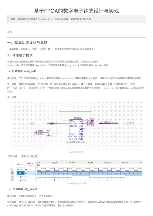
1、动态显⽰模块该模块主要功能是通过数码管的动态扫描实现 6 位数码管显⽰计数结果,本模块由扫描模块scan_cnt6,位选控制模块 dig_select,数据选择控制模块 seg_select 以及译码模块 decoder 构成扫描模块 scan_cnt6模块功能:产⽣ 位选控制端dig_select 和数据选择端 code_select 模块所需要的地址信息,扫描时钟决定位选信号和数据切换的速度。
设计思路:利⽤74390芯⽚(P160 TTL 双⼗进制异步计数器)构建⼀个模六计数器,就是6进制计数器,利⽤计数到6(110)时,“q2”和“q1”为⾼电平,产⽣ ⼀个复位信号,加到74390的⾼电平有效的异步清0端“1CLR”上,使计数器回0,从⽽实现模六计数。
设计结果:cnt6模块设计图波形仿真:(默认为时序仿真)cnt6模块波形仿真图位选模块 dig_select模块功能:在地址端的控制下,产⽣位选信号。
设计思路:利⽤74138芯⽚(3线-8线译码器),当选通端输⼊端G1为⾼电平,选通端输⼊端G2AN和G2BN为低电平时,将扫描信号cnt6的输出作为输⼊信号,dig[5..0]是译码输出,输出低电平有效。
设计结果:dig_select模块设计图波形仿真:dig_select模块波形仿真图数据选择模块 seg_select模块功能:输⼊ 6 组数据,每组数据 4bit,本模块完成在地址端的控制下从6 组数据当中选择 1 组输出。
设计思路:利⽤74151芯⽚(P91 8选1数据选择器),在控制输⼊端GN为低电平时,将扫描信号的选择下,分别选中D[5..0]对应的输⼊信号输出为Y。
单片机技术课程设计数字电子钟学院:班级:姓名:学号:教师:摘要电子钟在生活中应用非常广泛,而一种简单方便的数字电子钟则更能受到人们的欢迎。
所以设计一个简易数字电子钟很有必要。
本电子钟采用AT89C52单片机为核心,使用12MHz 晶振与单片机AT89C52 相连接,通过软件编程的方法实现以24小时为一个周期,同时8位7段LED数码管(两个四位一体数码管)显示小时、分钟和秒的要求,并在计时过程中具有定时功能,当时间到达提前定好的时间进行蜂鸣报时。
该电子钟设有四个按键KEY1、KEY2、KEY3、KEY4和KEY5键,进行相应的操作就可实现校时、定时、复位功能。
具有时间显示、整点报时、校正等功能。
走时准确、显示直观、运行稳定等优点。
具有极高的推广应用价值。
关键词:电子钟 AT89C52 硬件设计软件设计目录NO TABLE OF CONTENTS ENTRIES FOUND.一、数字电子钟设计任务、功能要求说明及方案介绍1.1 设计课题设计任务设计一个具有特定功能的电子钟。
具有时间显示,并有时间设定,时间调整功能。
1.2 设计课题的功能要求说明设计一个具有特定功能的电子钟。
该电子钟上电或按键复位后能自动显示系统提示符“d.1004-22”,进入时钟准备状态;第一次按电子钟启动/调整键,电子钟从12时59分0秒开始运行,进入时钟运行状态;按电子钟S5键,则电子钟进入时钟调整状态,此时可利用各调整键调整时间,调整结束后可按S5键再次进入时钟运行状态。
1.3 设计课的设计总体方案介绍及工作原理说明本电子钟主要由单片机、键盘、显示接口电路和复位电路构成,设计课题的总体方案如图1所示:图1-1总体设计方案图本电子钟的所有的软件、参数均存放在AT89C52的Flash ROM和内部RAM 中,减少了芯片的使用数量简化了整体电路也降低了整机的工作电流。
键盘采用动态扫描方式。
利用单片机定时器及计数器产生定时效果通过编程形成数字钟效果,再利用数码管动态扫描显示单片机内部处理的数据,同时通过端口读入当前外部控制状态来改变程序的不同状态,实现不同功能。
基于STC89C52单片机时钟的设计与实现1. 本文概述本文主要介绍了基于STC89C52单片机和DS1302时钟芯片的电子时钟设计与实现。
该电子时钟系统具有年月日等基本时间显示功能,并集成了秒表计时处理、闹钟定时、蜂鸣器和温度显示等附加功能。
系统采用LCD1602作为液晶显示器件,通过单片机对时钟和温度等数据进行处理后传输至LCD进行显示。
用户可以通过按键对时间进行调节,同时,单片机还通过扩展外围接口实现了温度采集等功能。
本文的目标是提供一个功能丰富、易于操作的电子时钟系统,为学习和应用单片机技术提供一个实用的案例。
2. 系统设计要求在设计基于STC89C52单片机的时钟系统时,我们需要考虑以下几个关键的设计要求:时钟系统必须具备基本的时间显示功能,能够以小时、分钟和秒为单位准确显示当前时间。
系统还应支持设置闹钟功能,允许用户设定特定的时间点进行提醒。
系统需要保证长时间稳定运行,具备良好的抗干扰能力,确保在各种环境下都能准确计时。
还应具备一定的容错能力,即使在操作失误或外部干扰的情况下,也能保证系统的正常运行。
用户界面应简洁直观,便于用户快速理解和操作。
时钟的显示部分应清晰可见,即使在光线较暗的环境下也能保持良好的可视性。
同时,设置和调整时间的操作应简单易懂,方便用户进行日常使用。
在设计时钟系统时,应考虑到未来可能的功能扩展,如温度显示、日期显示等。
系统的设计应具有一定的灵活性和扩展性,以便在未来可以轻松添加新的功能模块。
鉴于时钟系统可能需要长时间运行,能耗是一个重要的考虑因素。
设计时应选择低功耗的元件,并优化电源管理策略,以延长电池寿命或减少能源消耗。
在满足上述所有要求的同时,还需要控制成本,确保产品的市场竞争力。
这可能涉及到对单片机的编程优化、选择性价比高的外围元件等措施。
通过满足上述设计要求,我们可以确保开发出一个功能完善、稳定可靠、用户友好、易于扩展、节能环保且成本效益高的STC89C52单片机时钟系统。
本科毕业论文基于89C51单片机电子数字时钟的设计目录第一章第一章 电子时钟的总体设计电子时钟的总体设计 ....................................................................................................... ...................................................................................................... 44 1.1 设计目的设计目的.......................................................................................................................... 4 1.1.1 课程设计课程设计 ............................................................................................................... 4 1.1.2 AT89C51芯片的串口功能芯片的串口功能.................................................................................... 4 1.1.3用keil 软件进行编程与调试 .................................................................................. 4 1.2 设计任务设计任务 .......................................................................................................................... 4 1.3 设计思路设计思路.......................................................................................................................... 4 第二章第二章 硬件系统的设计硬件系统的设计............................................................................................................... .............................................................................................................. 66 2.1 电路原理图设计电路原理图设计 .............................................................................................................. 6 2.1.1 电子钟的硬件电路框图电子钟的硬件电路框图...................................................................................... 6 2.2 AT89C51引脚及其功能 (6)2.2.1 AT89C51的原理及说明的原理及说明 ........................................................................................ 6 2.2.2 引脚功能引脚功能 ............................................................................................................... 7 2.3 驱动部件驱动部件 .......................................................................................................................... 8 2.4 显示部分显示部分.......................................................................................................................... 9 第三章第三章 软件系统的设计软件系统的设计............................................................................................................. ............................................................................................................ 110 3.1 电子钟的主程序电子钟的主程序............................................................................................................ 11 3.2 电子钟的显示子序电子钟的显示子序 ........................................................................................................ 12 3.3 定时器中断服务程序定时器中断服务程序 .................................................................................................... 13 3.4 电子时钟设计程序清单电子时钟设计程序清单 ................................................................................................ 15 3.5 程序进行编译仿真程序进行编译仿真........................................................................................................ 18 3.5.1 89C51程序 ......................................................................................................... 18 3.5.2 用PROTEUS ISIS 进行电子万年历的仿真测试 . (20)第四章第四章对89C51设计的电子时钟的总结................................................................................. 22 参考文献 ........................................................................................................................................ . (2)23摘要本次实训是基于AT89C51单片机电子钟的设计,对时、分、秒的显示的控制,时、分、秒用六位数码管显示LED 数码管时钟电路采用24小时计时方式。
课程设计---基于Verilog HDL数字时钟设
计与实现
简介
本课程设计旨在通过使用Verilog硬件描述语言(HDL)设计和实现数字时钟。
学生将研究如何使用Verilog语言来描述数字电路,并将其应用于设计和实现一个简单的数字时钟电路。
设计目标
- 研究使用Verilog HDL来描述和设计数字电路
- 实现一个简单的数字时钟电路
- 熟悉数字时钟的工作原理和设计流程
实施步骤
1. 了解数字时钟的原理和工作方式
2. 研究Verilog HDL语言的基本语法和使用方法
3. 设计并实现时钟的各个功能模块,如时钟显示模块、时钟计数模块等
4. 使用仿真工具验证设计的正确性
5. 进行实际的硬件验证,将设计烧录到FPGA开发板上并进行测试
实验要求
1. 设计的数字时钟应具备基本的时分秒显示功能
2. 时钟应具备可调节的时间设置功能
3. 需要使用FPGA开发板进行实际硬件验证
4. 实验报告应包含设计原理、设计流程、仿真结果和实际硬件验证结果
参考资料
1. Verilog HDL教程
2. FPGA开发板用户手册
3. 相关学术论文和文献
以上为课程设计---基于Verilog HDL数字时钟设计与实现的文档简介。
本课程设计将帮助学生学习Verilog HDL语言并应用于设计和实现数字时钟电路。
基于Multisim的数字时钟仿真设计
Multisim是由National Instruments公司推出的一款仿真电路设计软件,其功能强大、界面友好,能帮助工程师更好地模拟电子电路。
本文介绍了在Multisim中进行数字时钟仿真设计的基本步骤。
在制作数字时钟之前,首先需要进行电路设计,具体步骤如下:
1、确定时钟的频率。
为了使Multisim能正常工作,必须确定正确的输入频率。
2、在Multisim中设置时钟电路。
在Multisim中,可以选择运放IC作为时钟电路的组件,并在模拟真实电路中调节不同的参数,比如时钟信号的频率和阻抗。
4、将时钟信号输出到外部仪器。
当仿真结果符合预期时,就可以将时钟信号输出到仪器中,进行更进一步的测试。
以上就是在Multisim中进行数字时钟仿真设计的基本流程,它能够帮助工程师更好地掌握设计思想,让电路设计更加容易和准确。
基于FPGA的数字时钟的设计课题:基于FPGA的数字时钟的设计学院:电气信息工程学院专业:测量控制与仪器班级: 08测控(2)班**:***学号: ********合作者姓名:颜志林2010 年12 月12 日综述近年来随着数字技术的迅速发展,各种中、大规模集成电路在数字系统、控制系统、信号处理等方面都得到了广泛的应用。
这就迫切要求理工科大学生熟悉和掌握常用中、大规模集成电路功能及其在实际中的应用方法,除通过实验教学培养数字电路的基本实验方法、分析问题和故障检查方法以及双踪示波器等常用仪器使用方法等基本电路的基本实验技能外,还必须培养大学生工程设计和组织实验能力。
本次课程设计的目的在于培养学生对基本电路的应用和掌握,使学生在实验原理的指导下,初步具备基本电路的分析和设计能力,并掌握其应用方法;自行拟定实验步骤,检查和排除故障、分析和处理实验结果及撰写实验报告的能力。
综合实验的设计目的是培养学生初步掌握小型数字系统的设计能力,包括选择设计方案,进行电路设计、安装、调试等环节,运用所学知识进行工程设计、提高实验技能的实践。
数字电子钟是一种计时装置,它具有时、分、秒计时功能和显示时间功能;具有整点报时功能。
本次设计我查阅了大量的文献资料,学到了很多关于数字电路方面的知识,并且更加巩固和掌握了课堂上所学的课本知识,使自己对数字电子技术有了更进一步的认识和了解。
1、课题要求1.1课程设计的性质与任务本课程是电子与信息类专业的专业的专业基础必修课——“数字电路”的配套实验课程。
目的在于培养学生的理论联系实际,分析和解决问题的能力。
通过本课程设计,使学生在理论设计、计算机仿真、指标调测、故障排除等方面得到进一步的训练,加强学生的实践能力。
学生通过设计、仿真、调试、撰写设计报告等过程,培养学生的动手能力和严谨的工作作风。
1.2课程设计的基本技术要求1)根据课题要求,复习巩固数字电路有关专业基础知识;2)掌握数字电路的设计方法,特别是熟悉模块化的设计思想;3) 掌握QUARTUS-2软件的使用方法;4) 熟练掌握EDA工具的使用,特别是原理图输入,波形仿真,能对仿真波形进行分析;5) 具备EDA技术基础,能够熟练使用VHDL语言进行编程,掌握层次化设计方法;6) 掌握多功能数字钟的工作原理,学会不同进制计数器及时钟控制电路的设计方法;7) 能根据设计要求对设计电路进行仿真和测试;8) 掌握将所设计软件下载到FPGA芯片的下载步骤等等。
单片机技术课程设计数字电子钟学院:班级:姓名:学号:教师:摘要电子钟在生活中应用非常广泛,而一种简单方便的数字电子钟则更能受到人们的欢迎。
所以设计一个简易数字电子钟很有必要。
本电子钟采用AT89C52单片机为核心,使用12MHz 晶振与单片机AT89C52 相连接,通过软件编程的方法实现以24小时为一个周期,同时8位7段LED数码管(两个四位一体数码管)显示小时、分钟和秒的要求,并在计时过程中具有定时功能,当时间到达提前定好的时间进行蜂鸣报时。
该电子钟设有四个按键KEY1、KEY2、KEY3、KEY4和KEY5键,进行相应的操作就可实现校时、定时、复位功能。
具有时间显示、整点报时、校正等功能。
走时准确、显示直观、运行稳定等优点。
具有极高的推广应用价值。
关键词:电子钟 AT89C52 硬件设计软件设计目录一、数字电子钟设计任务、功能要求说明及方案介绍 (4)1.1 设计课题设计任务 (4)1.2 设计课题的功能要求说明 (4)1.3 设计课的设计总体方案介绍及工作原理说明 (4)二、设计课题的硬件系统的设计 (5)2.1硬件系统各模块功能简要介绍 (5)2.1.1 AT89C52简介 (5)2.1.2 按键电路 (6)三、设计课题的软件系统的设计 (6)3.1 使用单片机资源的情况 (6)3.2 软件系统个模块功能简要介绍 (7)3.3 软件系统程序流程框图 (7)3.4 软件系统程序清单 (7)四、设计课题的设计结论、仿真结果、误差分析 (9)4.1 设计结论及使用说明 (9)4.2 仿真结果 (10)结束语 (12)参考文献 (12)附录 (13)附录A:程序清单 (13)一、数字电子钟设计任务、功能要求说明及方案介绍1.1 设计课题设计任务设计一个具有特定功能的电子钟。
具有时间显示,并有时间设定,时间调整功能。
1.2 设计课题的功能要求说明设计一个具有特定功能的电子钟。
该电子钟上电或按键复位后能自动显示系统提示符“d.1004-22”,进入时钟准备状态;第一次按电子钟启动/调整键,电子钟从12时59分0秒开始运行,进入时钟运行状态;按电子钟S5键,则电子钟进入时钟调整状态,此时可利用各调整键调整时间,调整结束后可按S5键再次进入时钟运行状态。
基于单片机的电子时钟的设计基于单片机的电子时钟是一种采用单片机作为主控芯片的数字显示时钟。
它能够准确显示时间,并可以通过编程实现其他功能,如闹钟、倒计时、温湿度显示等。
本文将介绍基于单片机的电子时钟的设计原理、硬件电路和软件编程等内容。
1.设计原理基于单片机的电子时钟的设计原理是通过单片机的计时器和定时器模块来实现时间的计数和显示。
单片机的计时器可以通过设定一个固定的时钟频率进行计数,而定时器可以设定一个固定的计数值,当计数到达设定值时,会触发一个中断,通过中断服务程序可以实现时间的更新和显示。
2.硬件电路基于单片机的电子时钟的硬件电路主要包括单片机、显示模块、按键模块和时钟模块。
其中,单片机作为主控芯片,负责控制整个电子时钟的运行;显示模块一般采用数字管或液晶屏,用于显示时间;按键模块用于设置和调整时间等功能;时钟模块用于提供稳定的时钟信号。
3.软件编程基于单片机的电子时钟的软件编程主要分为初始化和主程序两个部分。
初始化部分主要是对单片机进行相关寄存器的设置,包括计时器和定时器的初始化、中断的使能等;主程序部分是一个循环程序,不断地进行时间的计数和显示。
3.1初始化部分初始化部分首先要设置计时器模块的时钟源和计数模式,一般可以选择内部时钟或外部时钟作为时钟源,并设置计时器的计数模式,如自动重装载模式或单次模式;然后要设置定时器模块的计数值,一般可以通过设定一个固定的计数值和计数频率来计算出定时时间;最后要设置中断使能,使得当定时器计数器达到设定值时触发一个中断。
3.2主程序部分主程序部分主要是一个循环程序,通过不断地读取计时器的计数值,并计算得到对应的时间,然后将时间转换成显示的格式,并显示在显示模块上。
同时,还可以通过按键来实现时间的设置和调整功能,如增加和减少小时和分钟的值,并保存到相应的寄存器中。
4.功能扩展-闹钟功能:设置闹钟时间,并在设定的时间到达时触发报警;-温湿度显示:通过连接温湿度传感器,实时显示当前的温度和湿度数据;-倒计时功能:设置一个倒计时的时间,并在计时到达时触发相应的动作。
基于单片机的电子时钟的设计与实现电子时钟是一种使用微处理器或单片机作为主控制器的数字时钟。
它不仅能够显示当前时间,还可以具备其他附加功能,如闹钟、日历、温度显示等。
一、设计目标设计一个基于单片机的电子时钟,实现以下功能:1.显示时间:小时、分钟和秒钟的显示,采用7段LED数码管来显示。
2.闹钟功能:设置闹钟时间,到达设定的时间时会发出提示音。
3.日历功能:显示日期、星期和月份。
4.温度显示:通过温度传感器获取当前环境温度,并显示在LED数码管上。
5.键盘输入和控制:通过外部键盘进行时间、日期、闹钟、温度等参数的设置和调整。
二、硬件设计1.单片机选择:选择一款适合的单片机作为主控制器,应具备足够的输入/输出引脚、中断和定时器等功能,如STC89C522.时钟电路:使用晶振为单片机提供稳定的时钟源。
3.7段LED数码管:选择合适的尺寸和颜色的数码管,用于显示小时、分钟和秒钟。
4.温度传感器:选择一款适合的温度传感器,如DS18B20,用于获取环境温度。
5.喇叭:用于发出闹钟提示音。
6.外部键盘:选择一款适合的键盘,用于设置和调整时间、日期、闹钟等参数。
三、软件设计1.初始化:设置单片机定时器、外部中断和其他必要的配置。
2.时间显示:通过定时器中断,更新时间,并将小时、分钟和秒钟分别显示在相应的LED数码管上。
3.闹钟功能:设置闹钟时间,定时器中断检测当前时间是否与闹钟时间一致,若一致则触发警报。
4.日历功能:使用定时器中断,更新日期、星期和月份,并将其显示在LED数码管上。
5.温度显示:通过定时器中断,读取温度传感器的数据,并将温度显示在LED数码管上。
6.键盘输入和控制:通过外部中断,读取键盘输入,并根据输入进行相应的操作,如设置时间、闹钟、日期等。
7.警报控制:根据设置的闹钟时间,触发警报功能,同时根据用户的设置进行控制。
四、测试与调试完成软件设计后,进行系统测试与调试,包括验证显示时间、日期、温度等功能的准确性,以及闹钟和警报功能的触发与控制。
基于FPGA的数字时钟设计数字时钟是现代生活中必不可少的时间展示设备,广泛应用于各种场所,如家庭、办公室、学校等。
随着科技的不断发展,数字时钟的功能也得到不断升级,为人们日常生活提供了更多的便利和体验。
本文将介绍基于FPGA的数字时钟设计方案。
FPGA(Field Programmable Gate Array)是可编程门阵列的缩写,是一种现场可编程逻辑器件。
FPGA具有可编程性强、功能强大、极低的延迟等特点,被广泛应用于数字系统设计中。
本文中使用FPGA来实现数字时钟设计方案。
数字时钟的核心是计时电路,计时电路可以通过FPGA实现,使用FPGA来实现数字时钟的主要优点是可编程性强,能够满足不同需求的设计。
一、数字时钟的设计思路1、时钟信号的产生数字时钟的起点是时钟信号的产生,时钟信号的产生一般需要使用晶振。
晶振可以在一定频率范围内提供稳定的时钟信号。
FPGA可以通过将晶振与逻辑电路相连接,从而得到稳定的时钟信号。
2、计时电路的设计在数字时钟中,需要实现时、分、秒的计时功能。
这可以采用三个计时器来实现。
计时器可以使用FPGA内置的计数器实现,也可以通过逻辑电路实现。
计时器根据时钟信号的变化而变化,通过累计时钟信号的脉冲数计算出时、分、秒。
3、数码管的控制数字时钟的时间要通过数码管进行显示,数码管需要接受来自FPGA的控制信号才能正常显示数字。
通常采用多路复用器的方式来控制数码管的显示。
这里可以使用FPGA内置的多路复用器实现,FPGA输出控制信号,控制多路复用器选择哪个数码管进行显示。
数字时钟的硬件设计主要包括以下部分:时钟信号发生电路包含晶振以及晶振产生的时钟信号经过变压器传送到电路板上。
在电路板上,时钟信号经过电路处理,产生一定的电平和频率,供后续计时模块使用。
2、计时模块计时模块包括三个计时器,分别用于计算时、分、秒。
计时器通过累加时钟信号的脉冲数计算时间。
计时模块的输出需要送到数码管的控制模块进行显示。
摘要:本系统以AT89S52为核心,选用DS1302串行时钟芯片,RT1602液晶显示器实现液晶显示当前日期、时间、星期。
本电子钟具有日期、时、分、秒的显示、调整功能,采用的时间制式为24小时制,时间显示格式为时(十位、个位)、分(十位、个位)、秒(十位、个位)。
关键词AT89S52、显示时间、调整时间、目录一、设计任务及要求 (2)1.1设计任务 (2)1.2设计要求 (2)二、设计方案 (2)2.1时钟实现 (2)2.2显示模块 (2)2.3微控制器模块 (2)三、设计原理及实现 (2)3.1系统的总体设计方案 (2)3.1.1系统的硬件电路设计与主要参数计算 (3)3.2系统的软件设计 (7)3.2.1主程序流程 (7)3.2.2 ds1302子程序流程 (7)3.2.3调整时间子程序流程 (8)四、测试 (8)4.1硬件测试 (8)4.2软件测试 (8)4.3功能测试 (11)五、设计结论及体会 (11)设计结论: (11)体会 (11)致谢 (12)参考文献 (13)一、设计任务及要求1.1设计任务设计并制作一个用单片机控制的数字时钟。
1.2设计要求(1)显示时间——显示时,分,秒。
(2)设置时间——利用键盘手动设置时间。
(3)自动计时——自动计时并能实时显示二、设计方案根据期末单片机设计任务的总体要求,本系统可以划分为以下个基本模块,针对各个模块的功能要求,分别有以下的设计方案:2.1时钟实现采用专用的时钟芯片实现时钟的记时,专用时钟芯片记时准确,容易控制,能够从芯片直接读出日期、时间、星期。
2.2显示模块采用液晶显示器件,液晶显示平稳、省电、美观,更容易实现题目要求,对后续的功能兼容性高,只需将软件作修改即可,可操作性强,也易于读数,采用RT1602两行十六个字符的显示,能同时显示日期、时间、星期。
2.3微控制器模块采用AT89S52八位单片机实现。
它内存较大,有8K的字节FLASH闪速存储器,比AT89C51要多4K。
名目第一章绪论现代社会的标志之一确实是根基信息产品的广泛使用,而且是产品的性能越来越强,复杂程度越来越高,更新步伐越来越快。
支撑信息电子产品高速开展的根底确实是根基微电子制造工艺水平的提高和电子产品设计开发技术的开展。
前者以微细加工技术为代表,而后者的代表确实是根基电子设计自动化〔electronicdesignautomatic,EDA〕技术。
本设计采纳的VHDL是一种全方位的硬件描述语言,具有极强的描述能力,能支持系统行为级、存放器传输级和逻辑门级这三个不同层次的设计;支持结构、数据流、行为三种描述形式的混合描述,覆盖面广,抽象能力强,因此在实际应用中越来越广泛。
ASIC是专用的系统集成电路,是一种带有逻辑处理的加速处理器;而FPGA是特不的ASIC芯片,与其它的ASIC芯片相比,它具有设计开发周期短、设计制造本钞票低、开发工具先进、标准产品无需测试、质量稳定以及可实时在线检测等优点。
在操纵系统中,键盘是常用的人机交换接口,当所设置的功能键或数字键按下的时候,系统应该完成该键所对应的功能。
因此,按键信息输进是与软件结构紧密相关的过程。
依据键盘结构的不同,采纳不同的编码方法,但不管有无编码以及采纳什么样的编码,最后都要转换成为相应的键值,以实现按键功能程序的转移。
[1]钟表的数字化给人们生产生活带来了极大的方便,而且大大地扩展了钟表原先的报时功能。
诸如定时自动报警、定时启闭电路、定时开关烘箱、通断动力设备,甚至各种定时电气的自动启用等,所有这些根基上以钟表数字化为根底的。
因此研究数字钟以及扩大其应用有着特不现实的意义。
1.1选题背景本节将从FPGA嵌进式应用开发技术与数字钟技术开展的客瞧实际动身,通过对该技术开展状况的了解及课题本身的需要,指出研究基于FPGA的芯片系统与设计——数字钟的设计与实现的必要性。
课题相关技术的开展当今电子产品正向功能多元化,体积最小化,功耗最低化的方向开展。
它与传统的电子产品在设计上的显着区不是大量使用大规模可编程逻辑器件,使产品的性能提高,体积缩小,功耗落低,同时广泛运用现代计算机技术,提高产品的自动化程度和竞争力,缩短研发周期。
摘要之阿布丰王创作本设计为一个多功能的数字时钟,具有时、分、秒计数显示功能,以24小时循环计数;具有校对功能. 本设计采纳EDA技术,以硬件描述语言Verilog HDL为系统逻辑描述语言设计文件,在QUARTUSII工具软件环境下,采纳自顶向下的设计方法,由各个基本模块共同构建了一个基于FPGA的数字钟.系统由时钟模块、控制模块、计时模块、数据译码模块、显示以及组成.经编译和仿真所设计的法式,在可编程逻辑器件上下载验证,本系统能够完成时、分、秒的分别显示,按键进行校准,整点报时,闹钟功能.关键词:数字时钟,硬件描述语言,Verilog HDL,FPGAAbstractThe design for a multi-functional digital clock, with hours, minutes and seconds count display to a 24-hour cycle count; have proof functions function. The use of EDA design technology, hardware-description language VHDL description logic means for the system design documents, in QUAETUSII tools environment, a top-down design, by the various modules together build a FPGA-based digital clock. The main system make up of the clock module, control module, time module, data decoding module, display and broadcast module. After compiling the design and simulation procedures, the programmable logic device to download verification, the system can complete the hours, minutes and seconds respectively, using keys to cleared , to calibrating time. And on time alarm and clock for digital clock.Keywords:digital clock,hardware description language,Verilog HDL,FPGA目录第一章绪论1.1.选题意义与研究现状在这个时间就是金钱的年代里,数字电子钟已成为人们生活中的必需品.目前应用的数字钟不单可以实现对年、月、日、时、分、秒的数字显示,还能实现对电子钟所在地址的温度显示和智能闹钟功能,广泛应用于车站、医院、机场、码头、茅厕等公共场所的时间显示.随着现场可编程门阵列( field program-mable gate array ,FPGA) 的呈现,电子系统向集成化、年夜规模和高速度等方向发展的趋势更加明显, 作为可编程的集成度较高的ASIC,可在芯片级实现任意数字逻辑电路,从而可以简化硬件电路,提高系统工作速度,缩短产物研发周期.故利用 FPGA这一新的技术手段来研究电子钟有重要的现实意义.设计采纳FPGA现场可编程技术,运用自顶向下的设计思想设计电子钟.防止了硬件电路的焊接与调试,而且由于FPGA的 I /O 端口丰富,内部逻辑可随意更改,使得数字电子钟的实现较为方便.本课题使用Cyclone EP1C6Q240的FPGA器件,完成实现一个可以计时的数字时钟.该系统具有显示时、分、秒,智能闹钟,按键实现校准时钟,整点报时等功能.满足人们获得精确时间以及时间提醒的需求,方便人们生活.1.2.国内外研究及趋势随着人们生活水平的提高和生活节奏的加快,对时间的要求越来越高,精准数字计时的消费需求也是越来越多.二十一世纪的今天,最具代表性的计时产物就是电子时钟,它是近代世界钟表业界的第三次革命.第一次是摆和摆轮游丝的发明,相对稳定的机械振荡频率源使钟表的走时差从分级缩小到秒级,代表性的产物就是带有摆或摆轮游丝的机械钟或表.第二次革命是石英晶体振荡器的应用,发明了走时精度更高的石英电子钟表,使钟表的走时月差从分级缩小到秒级.第三次革命就是单片机数码计时技术的应用,使计时产物的走时日差从分级缩小到1/600万秒,从原有传统指针计时的方式发展为人们日常更为熟悉的夜光数字显示方式,直观明了,并增加了全自动日期、星期的显示功能,它更符合消费者的生活需求!因此,电子时钟的呈现带来了钟表计时业界跨跃性的进步.我国生产的电子时钟有很多种,总体上来说以研究多功能电子时钟为主,使电子时钟除原有的显示时间基本功能外,还具有闹铃,报警等功能.商家生产的电子时钟更从质量,价格,实用上考虑,不竭的改进电子时钟的设计,使其更加的具有市场.1.3.论文结构第一章详细论述了近些年来,数字化时钟系统研究领域的静态及整个数字化时钟系统的发展状况,同时分析了所面临的问题与解决方案,从而提出了本论文的研究任务.第二章从研究任务着手,选择符合设计要求的经常使用芯片及其它元器件,详细论述了各接口电路的设计与连接,以模块化的形式,整合数字化时钟硬件的设计从小到年夜,从局部到整体,循序渐进,最终实现一个功能齐全的数字化时钟系统.第三章根据系统设计要求,着手对数字化时钟系统软件进行功能的实现,将各功能模块有机结合,实现时钟走时,实现闹铃、整点报时附加功能.第四章依照设计思路,在联机调试过程中,对时钟系统的缺乏和缺点进行分析,将调试过程作重点的记录.第五章对全文的总结,对本系统功能实现以及制作过程中需要注意的方面,及整个系统软件编写中所吸取的经验教训进行论述,同时,也对整个研究应用进行展望.第二章编程软件及语言介绍2.1Quarters II编程环境介绍运行环境设计采纳quartus II软件实现,因此针对软件需要用到的一些功能在这里进行描述.Quartus II软件界面简单易把持,如下图2.1:图2.1Quartus II软件界面图2.1.1菜单栏1)【File】菜单Quartus II的【 File】菜单除具有文件管理的功能外,还有许多其他选项图2.2Quartus II菜单栏图(1)【New 】选项:新建工程或文件,其下还有子菜单【New Quartus II Project】选项:新建工程.【Design File】选项:新建设计文件,经常使用的有:AHDL文本文件、VHDL文本文件、Verilog HDL文本文件、原理图文件等.【Vector Waveform Five】选项:矢量波形文件.(2)【Open】选项:翻开一个文件.(3)【New Project Wizard 】选项:创立新工程.点击后弹出对话框.单击对话框最上第一栏右侧的“…”按钮,找到文件夹已存盘的文件,再单击翻开按钮,既呈现如图所示的设置情况.对话框中第一行暗示工程所在的工作库文件夹,第二行暗示此项工程的工程名,第三行暗示顶层文件的实体名,一般与工程名相同.图2.3Quartus II新建工程图(4)【creat /update】选项:生成元件符号.可以将设计的电路封装成一个元件符号,供以后在原理图编纂器下进行条理设计时调用.2)【View】菜单:进行全屏显示或对窗口进行切换,包括条理窗口、状态窗口、消息窗口等.图2.4Quartus II菜单栏全屏切换图3)【Assignments】菜单(1)【Device】选项:为以后设计选择器件.(2)【Pin】选项:为以后条理树的一个或多个逻辑功能块分配芯片引脚或芯片内的位置.(3)【Timing Ananlysis Setting】选项:为以后设计的 tpd、tco、tsu、fmax 等时间参数设按时序要求.(4)【EDA tool setting】选项:EDA 设置工具.使用此工具可以对工程进行综合、仿真、时序分析,等等.EDA 设置工具属于第三方工具.(5)【Setting】选项:设置控制.可以使用它对工程、文件、参数等进行修改,还可以设置编译器、仿真器、时序分析、功耗分析等.(6)【assignment editor】选项:任务编纂器.(7)【pin planner 】选项:可以使用它将所设计电路的 I/O 引脚合理的分配到已设定器件的引脚上.图2.5Quartus II菜单栏设定引脚下拉图4)【processing】菜单【processing】菜单的功能是对所设计的电路进行编译和检查设计的正确性. (1)【Stop process】选项:停止编译设计项目.(2)【Start Compilation】选项:开始完全编译过程,这里包括分析与综合、适配、装配文件、按时分析、网表文件提取等过程.(3)【analyze current file】选项:分析以后的设计文件,主要是对以后设计文件的语法、语序进行检查.(4)【compilation report】选项:适配信息陈说,通过它可以检查详细的适配信息,包括设置和适配结果等.(5)【start simulation】选项:开始功能仿真.(6)【simulation report】选项:生胜利能仿真陈说.(7)【compiler tool】选项:它是一个编译工具,可以有选择对项目中的各个文件进行分别编译.(8)【simulation tool】选项:对编译过电路进行功能仿真和时序仿真. (9)【classic timing analyzer tool】选项:classic时序仿真工具.(10)【powerplay power analyzer tool】选项:PowerPlay 功耗分析工具.图2.6Quartus II菜单栏运行下拉图5)【tools】菜单【tools 】菜单的功能是(1)【run EDA simulation tool 】选项:运行EDA仿真工具,EDA是第三方仿真工具.(2)【run EDA timing analyzer tool 】选项:运行EDA时序分析工具,EDA 是第三方仿真工具.(3)【Programmer 】选项:翻开编程器窗口,以便对Altera 的器件进行下载编程.图2.7Quartus II仿真菜单下拉图2.1.2工具栏工具栏紧邻菜单栏下方,它其实是各菜单功能的快捷按钮组合区.2.8Quartus II菜单栏图图2.9Quartus II菜单栏按键功能图2.1.3功能仿真流程1、新建仿真文件图2.10Quartus II菜单栏新建文件夹图2、功能方正把持在菜单上点processing在下拉菜单中,如下图:图2.11Quartus II菜单栏processing下拉图2.2Verilog HDL语言介2.2.1什么是verilog HDL语言Verilog HDL是一种硬件描述语言,用于从算法级、门级到开关级的多种笼统设计条理的数字系统建模.被建模的数字系统对象的复杂性可以介于简单的门和完整的电子数字系统之间.数字系统能够按条理描述,并可在相同描述中显式地进行时序建模.Verilog HDL 语言具有下述描述能力:设计的行为特性、设计的数据流特性、设计的结构组成以及包括响应监控和设计验证方面的时延和波形发生机制.所有这些都使用同一种建模语言.另外,Verilog HDL语言提供了编程语言接口,通过该接口可以在模拟、验证期间从设计外部访问设计,包括模拟的具体控制和运行.Verilog HDL语言不单界说了语法,而且对每个语法结构都界说了清晰的模拟、仿真语义.因此,用这种语言编写的模型能够使用Ve rilog仿真器进行验证.语言从C编程语言中继承了多种把持符和结构.Verilog HDL提供了扩展的建模能力,其中许多扩展最初很难理解.可是,Verilog HDL语言的核心子集非常易于学习和使用,这对年夜大都建模应用来说已经足够.固然,完整的硬件描述语言足以对从最复杂的芯片到完整的电子系统进行描述.2.2.2主要功能下面列出的是Verilog硬件描述语言的主要能力:●基本逻辑门,例如and、or和nan d等都内置在语言中.●用户界说原语(UP)创立的灵活性.用户界说的原语既可以是组合逻辑原语,也可以是时序逻辑原语.●开关级基本结构模型,例如pmos和nmos等也被内置在语言中.●提供显式语言结构指定设计中的端口到端口的时延及路径时延和设计的时序检查.●可采纳三种分歧方式或混合方式对设计建模.这些方式包括:行为描述方式—使用过程化结构建模;数据流方式—使用连续赋值语句方式建模;结构化方式—使用门和模块实例语句描述建模.●Verilog HDL中有两类数据类型:线网数据类型和寄存器数据类型.线网类型暗示构件间的物理连线,而寄存器类型暗示笼统的数据存储元件.●能够描述条理设计,可使用模块实例结构描述任何条理.●设计的规模可以是任意的;语言分歧毛病设计的规模(年夜小)施加任何限制.●Verilog HDL不再是某些公司的专有语言而是IEEE标准.●人和机器都可阅读Verilog语言,因此它可作为EDA的工具和设计者之间的交互语言.●Verilog HDL语言的描述能力能够通过使用编程语言接口(PLI)机制进一步扩展.PLI是允许外部函数访问Verilog模块内信息、允许设计者与模拟器交互的例程集合.●设计能够在多个条理上加以描述,从开关级、门级、寄存器传送级(RTL)到算法级,包括进程和队列级.●能够使用内置开关级原语在开关级对设计完整建模.●同一语言可用于生成模拟激励和指定测试的验证约束条件,例如输入值的指定.●Verilog HDL能够监控模拟验证的执行,即模拟验证执行过程中设计的值能够被监控和显示.这些值也能够用于与期望值比力,在不匹配的情况下,打印陈说消息.●在行为级描述中,Verilog HDL不单能够在RTL级上进行设计描述,而且能够在体系结构级描述及其算法级行为上进行设计描述.●能够使用门和模块实例化语句在结构级进行结构描述.●如图显示了Verilog HDL的混合方式建模能力,即在一个设计中每个模块均可以在分歧设计条理上建模.●Verilog HDL还具有内置逻辑函数,例如&(按位与)和|(按位或).●对高级编程语言结构,例如条件语句、情况语句和循环语句,语言中都可以使用.●可以显式地对并发和按时进行建模.●提供强有力的文件读写能力.●语言在特定情况下是非确定性的,即在分歧的模拟器上模型可以发生分歧的结果;例如,事件队列上的事件顺序在标准中没有界说.图2.12混合设计条理图第三章数字化时钟系统硬件设计3.1系统核心板电路分析本系统采纳的开发平台标配的核心板是QuickSOPC,可以实现EDA、SOP 和DSP的实验及研发.本系统采纳QuickSOPC标准配置为Altera公司的EP1C6Q240C8芯片.(1)核心板的硬件资源核心板采纳4层板精心设计,采纳120针接口.QuickSOPC核心板的硬件原图3.1QuickSOPC硬件方块图(2)FPGA电路核心板QuickSOPC上所用的FPGA为Altera公司Cyclone系列的EP1C6Q240.EP1C6Q240包括有5980个逻辑单位和92Kbit的片上RAM.EP1C6Q240有185个用户I/O口,封装为240-Pin PQFP.核心板EP1C6Q240器件特性如表2-1.表3-1核心EP1C6Q240器件特性:特性核心板EP1C6Q240器件逻辑单位(LE)5980M4K RAM 块20RAM总量(bit)92160PLL(个) 2185最年夜用户I/O数(个)1167216配置二进制文件(.rbf)年夜小(bit)可选串行主动配置器件EPCS1/ EPCS4/ EPCS16(3)配置电路Cyclone FPGA的配置方式包括:主动配置模式、主动配置模式以及JTAG配置模式.本系统采纳的是JTAG配置模式下载配置数据到FPGA.通过JTAG结果,利用Quartus II软件可以直接对FPGA进行独自的硬件重新配置.Quartus II软件在编译时会自动生成用于JTAG配置的.sof文件.Cyclone FPGA设计成的JTAG指令比其他任何器件把持模式的优先级都高,因此JTAG配置可随时进行而不用等候其他配置模式完成.JTAG模式使用4个专门的信号引脚:TDI、TDO、TMS以及TCK.JTAG的3个输入脚TDI、TMS 和TCK具有内部弱上拉,上拉电阻年夜约为25kΩ.在JGTA进行配置的时候,所有用户I/O扣都为高阻态.(4)时钟电路FPGA内部没振荡电路,使用有源晶振是比力理想的选择.EP1C6Q240C8的输入的时钟频率范围为15.625~387MHz,经过内部的PLL电路后可输出15.625~275MHz的系统时钟.当输入时钟频率较低时,可以使用FPGA的内部PLL 调整FPGA所需的系统时钟,使系统运行速度更快.核心板包括一个48MHz的有源晶振作为系统的时钟源.如图2-2所示.为了获得一个稳定、精确的时钟频率,有源晶振的供电电源经过了LC滤波.本系统硬件整体设计框图如图2-3所示:图3.2数字时钟系统硬件电路总体框图3.2系统主板电路分析3.2.1时钟模块电路FPGA内部没振荡电路,使用有源晶振是比力理想的选择.EP1C6Q240C8的输入的时钟频率范围为15.625~387MHz,经过内部的PLL电路后可输出15.625~275MHz的系统时钟.当输入时钟频率较低时,可以使用FPGA的内部PLL 调整FPGA所需的系统时钟,使系统运行速度更快.核心板包括一个50MHz的有源晶振作为系统的时钟源.为了获得一个稳定、精确的时钟频率,有源晶振的供电电源经过了LC滤波.图3.3系统时钟电路图3.2.2显示电路由于本设计需要显示时间信息包括:时、分、秒,显所以采纳主板上七段数码管显示电路与系统连接实现显示模块的功能.主板上七段数码管显示电路如图2-4 所示,RP4和 RP6 是段码上的限流电阻,位码由于电流较年夜,采纳了三极管驱动.图3.4七段数码管显示电路图数码管 LED显示是工程项目中使用较广的一种输出显示器件.罕见的数管有共阴和共阳 2 种.共阴数码管是将 8 个发光二极管的阴极连接在一起作为公共端,而共阳数码管是将 8 个发光二极管的阳极连接在一起作为公共端.公共端常被称作位码,而将其他的 8 位称作段码.如图 2-5所示为共阳数码管及其电路,数码管有 8 个段分别为:h、g、f、e、d、c、b 和a(h 为小数点) ,只要公共端为高电平“1” ,某个段输出低电平“0”则相应的段就亮.图3.5七段数码管显示电路图从电路可以看出,数码管是共阳的,当位码驱动信号为 0时,对应的数码管才华把持;当段码驱动信号为 0 时,对应的段码点亮.3.2.3键盘控制电路键盘控制电路要实现时钟系统调时的功能和闹铃开关的功能.本设计采纳主板上的自力键盘来实现这两个功能.当键盘被按下是为“0”,未被按下是为“1”.电路连接图如图2-6所示.电路中为了防止FPGA的I/O设为输出且为高电平在按键下直接对地短路,电阻RP9、RP10对此都能起到呵护作用.图3.6 键盘电路图3.2.4蜂鸣电路设计如图2-7所示,蜂鸣器使用 PNP三极管进行驱动控制,蜂鸣器使用的是交流蜂鸣器.当在BEEP输入一定频率的脉冲时,蜂鸣器蜂鸣,改变输入频率可以改变蜂鸣器的响声.因此可以利用一个PWM 来控制BEEP,通过改变PWM 的频率来获得分歧的声响,也可以用来播放音乐.若把 JP7断开,Q4 截止,蜂鸣器停止蜂鸣.图3.7蜂鸣电路图第四章数字化时钟系统软件设计4.1整体方案介绍4.1.1整体设计描述设计中的数字时钟,带有按键校准,定点报时,数码管显示等功能.因此数字时钟所包括的模块可分为,分频模块,按键模块,计时校准模块,闹钟模块,LED显示模块,模块之间的关系下图:图4.1整体模块框图针对框图流程,设定出各个模块的需求:1、分频电路:针对计时器模块与闹钟设定模块的需求,可以知道分频模块需要生成一个1Hz的频率信号,确保计时模块可以正常计数.2、计时器模块:计数模块的作用是收到分频模块1Hz频率的信号线,能进行正确计时,而且可以通过按键进行时间的修改,且当整点时,给蜂鸣器发生使能信号,进行整点报时,播放音乐.3、闹钟设定模块:可根据按键的设定闹钟的时间,当计时模块的时间与闹钟设定模块的时间相等的时候,给蜂鸣器一个使能信号,蜂鸣器闹铃..4、蜂鸣器模块:根据计时模块,闹钟模块给出的使能信号,判定蜂鸣器是整点报时,还是闹钟响铃.整点报时会播放音乐,闹钟时嘀嘀嘀报警.5、LED显示模块:根据实际的需求显示计时模块的时间,还是闹钟设定模块的时间,8个七段码LED数码管,进行扫描方式显示数据.4.1.2整体信号界说对整个模块进行信号界说.接口及寄存器界说module clock(clk,key,dig,seg,beep);// 模块名 clockinput clk; // 输入时钟input [4:0] key; //输入按键,key[3:0]分别为秒,分钟,小时的增加按键.Key[4]为闹钟设置按键,key[5]为校准设置按键.output [7:0] dig; // 数码管选择输出引脚 aoutput [7:0] seg; // 数码管段输出引脚output beep; //蜂鸣器输出端reg [7:0] seg_r = 8'h0; //界说数码管输出寄存器reg [7:0] dig_r; //界说数码管选择输出寄存器reg [3:0] disp_dat; // 界说显示数据寄存器reg [8:0] count1; //界说计数寄存器reg [14:0] count; //界说计数中间寄存器reg [23:0] hour = 24'h235956; // 界说现在时刻寄存器reg [23:0] clktime = 24'h000000; //界说设定闹钟reg [1:0] keyen = 2'b11; // 界说标识表记标帜位reg [4:0] dout1 = 5'b11111;reg [4:0] dout2 = 5'b11111;reg [4:0] dout3 = 5'b11111; // 寄存器wire [4:0] key_done; // 按键消抖输出reg [15:0] beep_count = 16'h0; //蜂鸣器寄存器reg [15:0] beep_count_end = 16'hffff; //蜂鸣器截止寄存器reg clktime_en = 1'b1; //闹钟使能寄存器reg sec ; //1秒时钟reg clk1; //1ms时钟reg beep_r; //寄存器wire beepen; //闹钟使能信号4.1.3模块框图通过quartus II的creat symble for current file功能生成框图如下:图4.2生成的符号图分频模块实现,计数电路所需时钟信号为1HZ,而系统时钟为48MHZ,所以要对系统时钟进行分频以来满足电路的需要.4.2分频模块实现4.2.1分频模块描述对分频模块,关键是生成个1Hz的时钟信号.考虑到仿真的需要,模块中间生成1个1kHz的时钟信号.1Hz的信号的发生用来发生时钟的秒脉冲,框图如下图4.2:图4.3分频模块图4.2.2分频模块设计本系统法式设计时钟的准确与否主要取决于秒脉冲的精确度.为了保证计时准确,我们对系统时钟48MHz进行了48000分频生成1kHz信号clk1,在通过1kHz信号,生成1Hz信号clk.//1ms信号发生部份always @(posedge clk) // 界说 clock 上升沿触发begincount = count + 1'b1;if(count == 15'd24000) //0.5mS到了吗?begincount = 15'd0; //计数器清零clk1 = ~clk1; //置位秒标识表记标帜endend//秒信号发生部份always @(posedge clk1) // 界说 clock 上升沿触发begincount1 = count1 + 1'b1;if(count1 == 9'd500) //0.5S到了吗?begincount1 = 9'd0; //计数器清零sec = ~sec; //置位秒标识表记标帜endEnd4.2.3分频模块仿真通过设置功能仿真,检查代码的正确性5仿真结果图4.4分频模块波形仿真图右上图可以知道,计数寄存器count累加到23999时,重新酿成0,共计数了24000个值.触发clk1跳变,使得count1加一,count1累加到499的时候,下一个数据为0,共技术500个值.所以,sec信号的频率为1Hz,满足设计要求.5.1计时模块实现5.1.1计时模块描述与实现计时模块是采纳16进制来实现的,将hour[23,0]界说为其时分秒,其中hour[3,0]为其秒钟上的个位数值,hour[4,7]为其秒钟上的十位数值,以此类推分钟、时钟的个位和十位.当clk脉冲过来时,秒个位hour[3,0]便开始加1,当加到9时,秒十位加1,与此同时秒个位清零,继续加1.当秒十位hour[7,4]为5秒个位为9时(即59秒),分个位hour[11,8]加1,与此同时秒个位和秒十位都清零.以此类推,当分十位hour[15,12]为5和分个位为9时(即59分),时个位加1,与此同时分个位hour[19,16]和分十位都清零.那时分十位[23,20]为2和分个位为4,全部清零,开始重新计时.从功能上讲分别为模60计数器,模60计数器和模24计数器.//时间计算及校准部份always @(negedge sec)//计时处置beginhour[3:0] = hour[3:0] + 1'b1;//秒加 1if(hour[3:0] >= 4'ha)//加到10,复位beginhour[3:0] = 4'h0;hour[7:4] = hour[7:4] + 1'b1;// 秒的十位加一if(hour[7:4] >= 4'h6)//加到6,复位beginhour[7:4] = 4'h0;hour[11:8] = hour[11:8] + 1'b1;//分个位加一if(hour[11:8] >= 4'ha)//加到10,复位beginhour[11:8] = 4'h0;hour[15:12] = hour[15:12] + 1'b1;//分十位加一if(hour[15:12] >= 4'h6)//加到6,复位beginhour[15:12] = 4'h0;hour[19:16] = hour[19:16] + 1'b1;//时个位加一if(hour[19:16] >= 4'ha)//加到10,复位beginhour[19:16] = 4'h0;hour[23:20] = hour[23:20] + 1'b1;//时十位加一endif(hour[23:16] >= 8'h24)//加到24,复位hour[23:16] = 8'h0;endendendendendend5.1.2计时模块仿真对计时模块进行仿真,记录仿真波形图4.5计时模块仿真图由上图可见,当sec信号下降沿跳变时,hour寄出去会加1,也就相当于跳了一秒钟时间.当hour的时间为235959是,下一个计数器的值为000000,hour寄存器归零,相当于三更0点的时刻.仿真的结果达到预期,通过.5.2按键处置模块实现5.2.1按键处置模块描述框图如下图4.4:图4.6按键控制功能图模块讲计时部份和时间调整部份整合到一起,正常态的时候,时间正常运行,当key[5]被按下时,进入时间校准,可以通过key[2:0]三个键,分别对秒,分,时进行加1把持,从而进行时间校准.当key[3]被按下时,进入闹钟设定,可以通过key[2:0]三个键,分别对秒,分,时进行加1把持,从而进行闹钟的设定.图4.7按键模块仿真图通过按键key进行仿真控制,可以发现clktime会随着按键的按下,分别有时钟,分钟秒钟加1,仿真结果满足设计要求.5.2.2按键去抖处置模块设计按键模块实现去抖处置,及乒乓按键设计,确保后面的计时模块与闹钟模块的功能实现.assign key_done = key|dout3; // 按键消抖输出always @(posedge count1[5]) //按键去噪声begindout1 <= key;dout2 <= dout1;dout3 <= dout2; //连续赋值endalways @(negedge key_done[4])beginkeyen[1] = ~keyen[1]; //校准按键转换乒乓按键endalways @(negedge key_done[3])beginkeyen[0] = ~keyen[0]; //按时按键转换乒乓按键End5.2.3按键模块去抖仿真对按键去颤动仿真,同样才用功能仿真方式,这里不再重复设置与把持,如同上面的分频模块进行设置并进行仿真.Key寄存器为输入按键,初始化电路为高电平,当有按键按下去的时候,酿成低电平.因此改变key的值,观察仿真结果是否正确.功能仿真,记录仿真结果,如下图:图4.8按键模块仿真图通过上图可以知道,key_done会随着key的变动而发生相应的变动,并有消除噪声的作用,功能仿真正确,达到设计目的.5.3闹钟模块实现5.3.1闹钟模块设计本设计中,判断闹铃时间到,是通过判按时钟系统实时时间的时钟与分钟是否分别即是设定的闹铃时间的时钟、分钟、秒钟.那时间(hour[23:0])即是设定的闹钟时间(clktime[23:0])时,闹钟触发时,播放嘀嘀嘀报警声,闹钟会响10秒的时间(clktime[23:0]+10 >=hour[23:0]).正常情况下,闹铃时间到会进行为时1分钟的蜂鸣报时,可以通过按下闹钟按键key[3]使其停止.当闹铃设置为整点是,会先进行整点报时,然后进入闹铃.图4.9闹钟控制键功能图5.3.2闹钟设定模块仿真图4.10闹钟模块仿真图通过按键key进行仿真控制,可以发现clktime会随着按键的按下,分别有时钟,分钟秒钟加1,仿真结果满足设计要求.5.4蜂鸣器模块实现5.4.1蜂鸣器模块描述蜂鸣器模块负责整点报时,和闹铃的时候进行作声的作用.整点报时的时候,播放音乐,10秒音乐播报完后停止整点报时.闹钟触发时,播放嘀嘀嘀报警声.当闹铃设置为整点是,会先进行整点报时,然后进入闹铃.当闹钟设定键被按下,响起的蜂鸣声会被屏蔽.模块框图如下图4.9:5.4.2蜂鸣器模块实现//蜂鸣器的计数按时器always@(posedge clk)。
基于QuartusII的数字时钟的设计摘要QuartusII是Altera公司的综合性PLD/FPGA开发软件,支持原理图、VHDL、VerilogHDL以及AHDL等多种设计输入形式,内嵌自有的综合器以及仿真器,可以完成从设计输入到硬件配置的完整PLD设计流程。
QuartusII使用户可以充分利用成熟的模块,简化了设计的复杂性,加快了设计速度。
对第三方EDA工具的良好支持也使用户可以在设计流程的各个阶段使用熟悉的第三方EDA工具。
数字钟是一种用数字电路实现时、分、秒计时的装置,与机械实施中相比具有更高的准确性和直观性,且无机械装置,具有更长的使用寿命,已得到了广泛的使用。
在对EDA的课程有了初步的了解并掌握Quartus II软件的初步应用之后,我们决定将课题设置为应用Quartus II软件,设计出一个时间可调,并可以通过LED七段共阴极数码管来显示时、分、秒的简易数字钟。
关键词:QuartusII;VHDL;EDA;数字钟SummaryQuartusII is Altera company comprehensive PLD/FPGA development software, support principle diagram, VHDL, VerilogHDL and AHDL design input in the form of embedded own comprehensive device simulators, and can be done from the design input to the hardware configuration of the complete PLD design process.QuartusII allow users to take full advantage of mature modules, simplifies the design complexity, speed up the design.Good support for third-party EDA tools also allow users to use in the different stages of the design process is familiar withthird-party EDA tools.Digital clock is a kind of when using a digital circuit implementation, minutes and seconds timing device, a higher accuracy compared with the implementation of the mechanical and intuitive, and no mechanical device, has a longer service life, has been widely used.In the course of EDA have a preliminary understanding and mastering the Quartus II software after the initial application, we decided to set the topic for the application of the Quartus II software, design a time is adjustable, and can be through the 7 common cathode LED digital tube display hours, minutes and seconds of simple digital clock.Keywords:QuartusII;VHDL;EDA;digital clock目录摘要 (1)绪论 (5)1.课程设计的目的与作用 (7)2.设计任务 (7)3.QuartusII软件介绍 (7)4.相关理论 (8)4.1 理论 (8)4.2 器件 (8)5. 系统设计 (8)5.1 总体 (8)5.2 各模块 (9)5.2.1 顶层模块 (9)5.2.2 十进制计数器模块 (9)5.2.3 六进制计数器模块 (10)5.2.4 二十四进制计数器模块 (10)5.2.5 7段LED显示驱动模块 (11)6. 硬件设计 (11)6.1 顶层实体图 (11)6.2 各模块实体图 (12)6.2.1 十进制计数器模块 (12)6.2.2 六进制计数器模块 (12)6.2.3 二十四进制计数器模块 (13)6.2.4 7段LED显示驱动模块 (13)6.3 总体实体图 (14)7. 流程图设计 (15)8.模块设计实现 (16)8.1建立顶层模块 (16)8.1.1新建dianzizhong.工程 (16)8.1.2建立VHDL源程序 (16)8.2建立十进制计数器模块 (18)8.2.1新建CNT10.工程 (18)8.2.2建立VHDL源程序 (18)8.3建立六进制计数器模块 (19)8.3.1新建CNT6.工程 (19)8.3.2建立VHDL源程序 (19)8.4建立二十四进制计数器模块 (20)8.4.1新建CNT24.工程 (20)8.4.2建立VHDL源程序 (20)8.5建立7段LED显示驱动模块 (21)8.5.1新建LED_DRIV.工程 (21)8.5.2建立VHDL源程序 (22)9.仿真调试结果分析 (22)9.1顶层模块的编译与波形仿真 (22)9.2十进制计数器模块的编译与波形仿真 (23)9.3六进制计数器模块的编译与波形仿真 (24)9.4二十四进制计数器模块的编译与波形仿真 (25)9.5 7段LED显示驱动模块的编译与波形仿真 (26)10. 结论 (27)11.设计总结和体会 (27)12. 致谢 (28)13. 参考文献 (29)绪论1.研究的意义在快速发展的年代,时间对于人们来说越来越宝贵,在快节奏的生活中,人们往往会忘记了时间,一旦在一些重要的场合忘记了时间,将会带来重大的损失。
因此我们需要一个定时系统来提醒忙碌的人,数字钟无疑是一个极佳的选择。
数字钟是一种用数字电路实现时、分、秒计时的装置,与机械实施中相比具有更高的准确性和直观性,且无机械装置,具有更长的使用寿命,已得到了广泛的使用。
数字钟已成为人们日常生活中不可缺少的生活必需品,广泛的应用于家庭以及车站、码头、剧场办公室等公共场所,给人们的生活、学习、工作、娱乐带来了极大的方便。
2.国内外研究现状数字钟一般由振荡器,分频器,译码器,显示器等部分组成,这些都是数字电路中最基本的,应用最广的电路。
当前市场上已有现成数字钟集成电路芯片出售,价格较便宜由于数字集成电路技术的发展,采用了先进稳定的石英振荡技术,是数字钟具有走时准确,性能稳定,携带方便等特点,是目前人们生活和工作不可或缺的报时用品。
然而,近些年来,随着科技的发展和进步,人们对数字钟的要求也越来越高,传统的简易的功能单一的数字钟已不能满足人们的需求。
新出现的多功能时钟不管在性能上还是在样式上都发生了质的变化,有电子闹钟、数字闹钟等等。
而且在功能方面,也大大地扩展了钟表原先的报时功能。
研制出了具有诸如定时自动报警、按时自动打铃、时间程序自动控制、定时广播、自动起闭路灯、定时开关烘箱、通断动力设备、甚至各种定时电气的自动启用等功能的数字时钟,给人们带来了极大的便利。
3.研究思路和方法本学期,我们学习了EDA的课程,开始掌握Quartus II软件的初步应用。
因此,本组成员决定从数字钟这一项目进行展开,应用Quartus II软件,设计出一个时间可调,并可以通过LED七段共阴极数码管来显示时、分、秒的简易数字钟。
设计与实践部分基于QuartusII的数字时钟的设计1.课程设计的目的与作用(1)掌握基于FPGA的数字模块开发方法;(2)掌握QuartusII软件的使用方法;(3)假设外部输入脉冲为1Hz,使用该频率设计一个时间可调,并通过LED七段共阴极数码管能够显示时、分、秒的数字钟。
2.设计任务本次课程设计的任务是利用所学的EDA的理论知识作为分析设计指导,查阅资料书籍,设计出基于QuartusII的数字时钟,并对其用QuartusII软件仿真所设计的程序,并将仿真结果与之前的理论分析计算出的结果进行比较,若无差别,则可认为程序设计合理;若有差别,检查设计程序并做相应的修改,直至理论分析结果与实际仿真结果相同,完成课程设计的设计报告并进行答辩。
3.QuartusII软件介绍QuartusII是Altera公司的综合性PLD/FPGA开发软件,支持原理图、VHDL、VerilogHDL以及AHDL等多种设计输入形式,内嵌自有的综合器以及仿真器,可以完成从设计输入到硬件配置的完整PLD设计流程。
QuartusII使用户可以充分利用成熟的模块,简化了设计的复杂性,加快了设计速度。
对第三方EDA工具的良好支持也使用户可以在设计流程的各个阶段使用熟悉的第三方EDA工具。
QuartusII提供了完全集成且与电路结构无关的开发包环境,具有数字逻辑设计的全部特性,包括:可利用原理图、结构框图、VerilogHDL、AHDL和VHDL 完成电路描述,并将其保存为设计实体文件。
此外,Quartus II 通过和DSP Builder工具与Matlab/Simulink相结合,可以方便地实现各种DSP应用系统;支持Altera的片上可编程系统(SOPC)开发,集系统级设计、嵌入式软件开发、可编程逻辑设计于一体,是一种综合性的开发平台。
Maxplus II 作为Altera的上一代PLD设计软件,由于其出色的易用性而得到了广泛的应用。
目前Altera已经停止了对Maxplus II 的更新支持,Quartus II 与之相比不仅仅是支持器件类型的丰富和图形界面的改变。
Altera在Quartus II 中包含了许多诸如SignalTap II、Chip Editor和RTL Viewer的设计辅助工具,集成了SOPC和HardCopy设计流程,并且继承了Maxplus II 友好的图形界面及简便的使用方法。
Altera Quartus II 作为一种可编程逻辑的设计环境, 由于其强大的设计能力和直观易用的接口,越来越受到数字系统设计者的欢迎。
4. 相关理论4.1 设计理论及原理数字钟从原理上讲是一种典型的数字电路,其中包括了组合逻辑电路和时序电路。
本次设计的数字钟在设计时,先对1s的时钟进行计数,当计数达到60次时,输出一个分钟(min)脉冲;当1min的时钟计数达到60次时,输出1个小时(h)脉冲;若1h的时钟计数达到23次时,并且1min的技术达到59次、1s 的计数也达到59次,再来1个1s的脉冲,数字钟就自己复位,重新从零开始计时。