【VIP专享】即插即用温度保护移动电源方案ZS6599R _V025规格书
- 格式:pdf
- 大小:616.62 KB
- 文档页数:12
![[VIP专享]VAS5900充电器使用说明中文](https://uimg.taocdn.com/468807a9b90d6c85ed3ac637.webp)
PHOENIX ELITE PORTABLE SOLAR GENERATOREN01 USER GUIDE驭光者·火鸟ELITE太阳能手提式移动电源箱CN18PHOENIX ELITE PORTABLE SOLAR GENERATORUser GuideIMPORTANT SAFETY INSTRUCTIONS PACKAGE CONTENTS FEATURESRECHARGING PHOENIX ELITE LCD SCREENPRODUCT OVERVIEW SPECIFICATIONS TROUBLESHOOTINGFREQUENTLY ASKED QUESTIONS WARRANTYOPERATING PHOENIX ELITE MAINTENANCE 171613131108070604030302Please read the User Guide carefully before recharging or operating your PHOENIX Elite.IMPORTANT SYMBOLSIndicates potentially dangerous conditions that could result in personal injury Indicates conditions or practices that could result in damages to the unit or other equipmentIndicates procedures or functions that are important for proper and safe operation of the unit and/or other equipmentCAUTIONCAUTION CAUTION CAUTIONWARNINGWARNINGWARNINGWARNINGWARNINGWARNINGNOTEDO NOT submerge the unit in water or operate the unit in the rain. Doing so may cause short-circuits, electric shocks, and/or fire.DO NOT place the unit near fire and/or heat the unit. Doing so may cause irreversible damages to the unit and/or battery explosion.DO NOT overload the unit. Please check the specifications of output ports and devices before operation.Please turn off the output ports when no devices are connected to the unit to prevent electric shocks.DO NOT dismantle or modify the unit. Doing so may cause irreversible damages to the unit and void warranty.CAUTIONDO NOT place the unit in high-temperature situations. Doing so may cause unit malfunction or component degradation.CAUTIONDO NOT expose the unit to strong electrostatic fields, strong magnetic fields, and/or radiation.CAUTIONPlease check the unit before each use. Stop using the unit if you notice unusual smells, heating, distortion, or any other abnormalities.DO NOT drop or strike the unit. Doing so may cause circuit failures and cracks in the casing.Please dispose of the product according to the local recycling and environmental regulations.Keep the unit out of the reach of young children.PORTABLE DESIGNFeaturing a portable briefcase design with a sturdy carrying handle, the PHOENIX Elite is the top choice for a weekend trip or an emergency.RENEWABLE ENERGYDesigned for off-grid applications, the PHOENIX Elite combines two highly efficient 10W monocrystalline solar panels for effortless battery replenishment.DIVERSE RECHARGING OPTIONSEngineered with convenience and versatility in mind, the PHOENIX Elite supports recharging from car sockets, AC adapters, USB-C wall chargers, and external solar panels.RELIABLE POWER SOURCEEquipped with a 300Wh rechargeable lithium-ion battery pack and multiple output ports, the PHOENIX Elite is ready to provide long-lasting power for a wide range of mobile devices and small appliances.1 x Renogy PHOENIX Elite Portable Solar Generator1 x AC/DC Adapter1 x Cigarette Lighter Plug to 5.5mm DC Adapter Cable1 x Solar Panel Connectors to 5.5mm DC Adapter Cable1 x USB-C to USB-C Cable1 x User Guide76 12345891011121314CIG Port Output Side DoorDC Output Ports QC USB-A Port USB-A Ports Hinges Input Side Door 15DC Input Port 16USB-C PD Port 17LED Flashlight 18Carrying Handle1914131211109Flashlight On/Off Button Main Power ButtonAC Output Mode On/Off Button DC Output Mode On/Off Button LCD Screen Built-in Solar Panels Latches AC Outlet 876543211516171819InputBatteryGeneralLithium-ion 14.4V20800mAh / 299.5Wh Battery Type Battery Voltage Battery CapacityBuilt-in Solar Panel DC Input Port USB-C PD Port Total9.8V / 2.04A, 20W Max 9-16.8V, 55W Max 16.8-30V, 100W Max5V / 3A, 9V / 3A, 12V / 3A, 15V / 3A, 20V / 3A, 60W Max 180W Max 413 x 308 x 100 mm / 16.3 x 12.1 x 3.9 inch 5.3 kg / 11.7 lb.ABS + PC 3W LED0-45 ℃ / 32-113 ℉-10-60 ℃ / 14-140℉20-90%Dimension Weight Material FlashlightNormal Operating Temperature Storage Temperature Operating / Storage HumidityOutputUSB-A Port (2)QC USB-A Port USB-C PD Port CIG PortDC Output Port (2)AC OutletTotal5V / 2.4A Max5V / 3A, 9V / 2A, 12V / 1.5A, 18W Max5V / 3A, 9V / 3A, 12V / 3A, 15V / 3A, 20V / 3A, 60W Max 13.6V / 9A Max 13.6V / 4.5A Max 110V / 60Hz (US, JP, CA)220V / 50Hz (AU, EU, CN)200W Rated, 300W Surge Pure Sine Wave300W MaxThe LCD Screen will be lit when the PHOENIX Elite is being recharged or turned on to display the recharging and operating status of the PHOENIX Elite. Please refer to the following table to interpret the information displayed on the LCD Screen.The Battery Level is displayed as a ring composed of 10 segments with a percentage in the center. The ring and percentage appear when the PHOENIX Elite is being recharged or is turned on. When recharging the PHOENIX Elite, a lightning bolt will appear above the percentage. The ring will be lit segment by segment with the increasing percentage until the PHOENIX Elite has been fully recharged. As the PHOENIX Elite is used to power other devices, the ring segments will go out one by one with the decreasing percentage. When the battery level is lower than 10%, the last ring segment and the percentage will flash.IconNameDescriptionBattery LevelThe AC Output Mode is displayed as a rectangle with the words ‘AC Output’ inside. The rectangle appears when the AC output mode is activated with the AC Outlet turned on. The rectangle disappears when the AC output mode is deactivated with the AC Outlet turned off.AC Output ModeAC Output The DC Output Mode is displayed as a rectangle with the words ‘DC Output’ inside. The rectangle appears when the DC output mode is activated with the USB-A Ports, QC USB-A Port, USB-C PD Port, CIG Port, and DC Output Ports turned on. The rectangle disappears when the DC output mode is deactivated with the USB-A Ports, QC USB-A Port, USB-C PD Port, CIG Port, and DC Output Ports turned off.DC Output ModeThe Built-in Solar Panel Input is displayed as a sun with 5 bars below it. The sun and bars appear when the PHOENIX Elite detects input power from the Built-in Solar Panel. The number of bars demonstrates the strength of solar irradiance.Built-in Solar Panel InputThe Input Power is displayed as a wattage with the word ‘Input’ above it. The wattage appears when the PHOENIX Elite is being recharged.Input PowerThe Output Power is displayed as a wattage with the word ‘Output’ above it. The wattage appears when the AC output mode or the DC output mode is activated.Output PowerThe Error Code is displayed as a 3-digit code starting with the letter ‘E’. The code appears when the PHOENIX Elite encounters abnormal conditions.Error CodeDC OutputIf the [Error Code] icon appears, the PHOENIX Elite may need special attention. Please refer to the TROUBLESHOOTING section for help.CAUTIONTo maximize the battery life, please ensure that the PHOENIX Elite is fully recharged before operating or storing.To shorten the recharge time, it is highly recommended to disconnect all loads while recharging the PHOENIX Elite.CAUTIONNOTEThe above recharge times are based on conditions when the PHOENIX Elite is recharged at full speed with no loads connected to it.NOTEThe LCD Screen will go out if the input power of the Built-in Solar Panels is lower than 5W and no operations are made within 60 seconds. Press the AC Output Mode On/Off Button or DC Output Mode On/Off Button to relight the LCD Screen.NOTEThe recharge time via the Built-in Solar Panels is highly dependent on solar irradiance and ambient temperature.NOTERecharge TimeRecharge via Built-in Solar Panel: 20 Hours Recharging via Built-in Solar PanelFor optimal recharging performance, it is highly recommended to recharge the PHOENIX Elite using the Built-in Solar Panels on bright sunny days free of scattered clouds.Recharging via External Solar PanelFor optimal recharging performance, it is highly recommended to recharge the PHOENIX Elite using an external solar panel (not included) on bright sunny days free of scattered clouds.Place the external solar panel under direct sunlight. Steer clear of trees or branches that can shade the external solar panel and slow down the recharging process.Place the PHOENIX Elite in an open area. Open the Latches and adjust the angle of the Hinges to expose the Built-in Solar Panels to direct sunlight. Steer clear of trees or branches that can shade the Built-in Solar Panel and slow down the recharging process.The PHOENIX Elite will begin to recharge automatically. The LCD Screen will be lit with the [Battery Level] icon, [Built-in Solar Panel Input] icon, and [Input Power] icon appearing.Recharge via External Solar Panel: 4 HoursRecharge via both Built-in Solar Panel and External Solar Panel: 3.5 Hours Recharge via AC/DC Adapter: 6 Hours Recharge via Car Socket: 6 HoursRecharge via USB-C PD Wall Charger: 6 HoursRecharge via both AC/DC Adapter and USB-C PD Wall Charger: 3 HoursUse the included Solar Panel Connectors to 5.5mm DC Adapter cable to connect the external solar panel to the DC Input Port of the PHOENIX Elite. Place the PHOENIX Elite in the shade to prevent it from overheating.The PHOENIX Elite will begin to recharge automatically. The LCD Screen will be lit with the [Battery Level]icon and [Input Power] icon appearing.Compatible External Solar Panels:Renogy Monocrystalline Solar Panel: 50W, 80W, 100W, 160WRecharging via AC/DC Adapter Plug the PHOENIX Elite into a wall outlet through the DC Input Port using the included AC/DC Adapter.Renogy Polycrystalline Solar Panel: 50W, 100WRenogy ECLIPSE Series Solar Panel: 100WRenogy Monocrystalline Foldable Solar Suitcase w/o Controller: 100WRenogy ECLIPSE Series Foldable Solar Panel w/o Controller: 100W, 200WRenogy Flexible Solar Panel: 50W, 100W, 160W, 175WRenogy E.FLEX Series Portable Solar Panel: 50W, 100W, 120W CAUTION WARNING NOTEElectrical shock can occur if the Solar Panel Connectors to 5.5mm DC Adapter Cable isdamaged or frayed. DO NOT use a damaged or frayed cable to recharge the PHOENIX Elite.Please ensure that the open circuit voltage of the external solar panel does not exceed 30V orfall short of 9V.The recharge time via the external solar panel is highly dependent on solar irradiance andambient temperature.The PHOENIX Elite will begin to recharge automatically. The LCD Screen will be lit with the [Battery Level] icon and [Input Power] icon appearing.Recharging via Car SocketPlug the PHOENIX Elite into a car socket through the DC Input Port using the included Cigarette Lighter Plug to 5.5mm DC Adapter Cable.The PHOENIX Elite will begin to recharge automatically. The LCD Screen will be lit with the [Battery Level] icon and [Input Power] icon appearing.WARNINGElectrical shock can occur if the AC/DC Adapter is damaged. DO NOT use a damaged AC/DC Adapter to recharge the PHOENIX Elite.WARNING DO NOT use a third-party AC/DC adapter to charge the PHOENIX Elite. Doing so may cause the AC/DC adapter to overheat and/or fire.WARNING Electrical shock can occur if the Cigarette Lighter Plug to 5.5mm DC Adapter Cable is damaged or frayed. DO NOT use a damaged or frayed cable to recharge the PHOENIX Elite.CAUTIONPlease disconnect the PHOENIX Elite from the car socket when starting the engine. Electricalsurges from the alternator when starting may damage the PHOENIX EliteRecharging via USB-C PD Wall ChargerFor optimal recharging performance, it is highly recommended to recharge the PHOENIX Elite using a USB-C PD wall charger (not included) with a high power rating.Plug the PHOENIX Elite into a wall outlet through the USB-C PD Port using the USB-C PD wall charger and the included USB-C to USB-C Cable.The PHOENIX Elite will begin to recharge automatically. The LCD Screen will be lit with the [Battery Level] icon and [Input Power] icon appearing.WARNINGElectrical shock can occur if the USB-C PD wall charger is damaged. DO NOT use a damagedUSB-C PD wall charger to recharge the PHOENIX Elite.Recommended USB-C PD Wall Chargers:Apple USB-C Power Adapter: 30W, 61W, 87W, 96WOperation Time Battery Powered Devices:Google USB-C Power Adapter: 45WOperating the PHOENIX Elite at high temperature above 113℉ (45℃) or at low temperatures below 32℉ (0℃) can result in battery performance degradation and service life shortening. Foroptimal battery performance and maximum battery life, it is highly recommended to operate the PHOENIX Elite at room temperatures. CAUTION OPERATING PHOENIX ELITENumber of Full Charges =Device Battery Capacity (Wh)299.5Wh x 70%Powering DevicesPress the Main Power Button to turn on the PHOENIX Elite. The LCD Screen will be lit with the [Battery Level] icon appearing.Compatible DevicesUSB-A Ports / QC USB-A Ports: Smart Watch, Electronic Book, Smart Phone, Tablet, Action Camera, Digital Camera, Bluetooth Speaker, Wireless Headphone, Drone, and other USB-A enabled devicesUSB-C PD Ports: Smart Phone, Tablet, Laptop, Handheld Game Console, DSLR Camera, and other USB-C enabled devicesCIG Port: Portable Refrigerator, Car Vacuum, Car Air Fan, CPAP Machine, and other car powered devices DC Output Ports: LED Strip Light, Modem, Router, Motor, and other DC powered devicesAC Outlet: Laptop, Monitor, TV, Game Console, Inkjet Printer, Portable Projector, Light Bulb, and other AC Powered DevicesTo use the USB-A Ports, QC USB-A Port, USB-C PD Port, CIG Port, or DC Output Ports, first press the DC Output Mode On/Off Button to activate the DC output mode. The [DC Output Mode] icon and [Output Power] icon will appear. Then, connect the device(s) to the port(s) for power. The [Output Power] icon will show the real-time output power. When not using the port(s), long press the DC Output Mode On/Off Button to deactivate the DC output mode. The [DC Output Mode] icon and [Output Power] icon will disappear.To use the AC Outlet, first press the AC Output Mode On/Off Button to activate the AC output mode. The [AC Output Mode] icon and [Output Power] icon will appear. Then, connect the device to the outlet for power. The[Output Power] icon will show the real-time output power. When not using the outlet, long press the AC Output Mode On/Off Button to deactivate the AC output mode. The [AC Output Mode] icon and [Output Power] icon will disappear.When no device is connected to the PHOENIX Elite, press the Main Power Button again to turn it off.DC Powered Devices:Working Hours =Device Power Rating (W )299.5Wh x 95%AC Powered Devices:Working Hours =Device Power Rating (W )299.5Wh x 85%NOTE The above estimation formulas only apply when the PHOENIX Elite has been fully recharged and the device does not draw too much power.NOTEActual number of full charges and working hours may vary due to different powering methods and device operation status.WARNINGThe PHOENIX Elite can provide up to 300W total output power. Allocate the total output powerrationally and follow the specifications of each output port. DO NOT overload the PHOENIXElite. If the total output power should exceed 300W, the AC Outlet will be shut off.Using LED FlashlightPress the Main Power Button to turn on the PHOENIX Elite. The LCD Screen will be lit with the [Battery Level] icon appearing.When not using the LED Flashlight, press the Main Power Button to turn off the PHOENIX Elite.The LED Flashlight has three lighting modes: bright (100% brightness), dim (50% brightness), and SOS. Press the Flashlight On/Off Button to turn on the LED Flashlight, switch lighting modes, and turn off the LED Flashlight. Long press the Flashlight On/Off Button to turn off the LED Flashlight no matter what lighting mode it is on.To prolong the service life of the PHOENIX Elite, keep it away from water, dust, and dirt. DO NOT leave the PHOENIX Elite in harsh environments.Keep the PHOENIX Elite away from corrosives, fire, and heat sources.Keep the PHOENIX Elite recharged when not in use and avoid connecting devices with high power ratings when the battery level is low.If the PHOENIX Elite does not operate normally, please refer to the following table for possible causes and corrective steps.If the following corrective steps do not work, please contact the Renogy technical support team for help. Refer to the last page of the User Guide for contact information.If the PHOENIX Elite is not used frequently, keep its battery level at around 50%. Store the PHOENIX Elite in a clean, dry, and well-ventilated environment with a temperature around 77℉ (25℃) and a humidity no higher than 75%. Recharge the PHOENIX Elite at least once every two months.NOTE The PHOENIX Elite may not be compatible with the devices that require high current impulses despite their conformity with the output ports specifications.NOTEThe PHOENIX Elite may not be able to deliver exactly 299.5Wh of energy when poweringdevices with high power ratings. Battery high temperature protection may be triggered when the PHOENIX Elite is operating at full load. Cool down the PHOENIX Elite before resuming operation. CAUTIONWhen using the AC Outlet, keep 4 inches of space on either side of the PHOENIX Elite to guarantee efficient heat dissipation.CAUTION When the battery level drops to 0%, the PHOENIX Elite will turn off automatically. Please recharge the PHOENIX Elite as soon as possible to avoid permanent damage to the battery.CAUTION When the battery level drops below 10%, use of the AC Outlet will be disabled. If the total outputpower still exceeds 200W, use of the CIG Port and DC Output Ports will be subsequentlydisabled. DO NOT connect devices with high power ratings to the PHOENIX Elite when the battery level is low. CAUTIONDisconnect all the power source(s). Discharge the unit untilthe [Error Code] icon disappears.Error CodePossible Causes Corrective Steps E01Battery Over-voltage Disconnect all the electrical load(s). Recharge the unit untilthe [Error Code] icon disappears.E02Battery Under-voltage Stop using the unit. Contact the Renogy technical supportteam for help.E03Battery Cell Imbalance Stop using the unit. Contact the Renogy technical supportteam for help.E04BMS Communication Failure Disconnect all the power source(s) and electrical load(s).Cool down the unit until the [Error Code] icon disappears.E05Battery High Temperature (Charge)Disconnect all the power source(s) and electrical load(s).Warm up the unit until the [Error Code] icon disappears.E06Battery Low Temperature (Charge)Disconnect the power source. Check the voltage rating ofthe power source. Connect only the power source withcompliant voltage rating to the unit.E07DC Input Port Over-voltage Disconnect the power source. Check the voltage rating ofthe power source. Connect only the power source withcompliant voltage rating to the unit.E08DC Input Port Under-voltage Disconnect the power source. Check the voltage rating ofthe power source. Connect only the power source withcompliant voltage rating to the unit.E09USB-C PD Port Input Over-voltage Disconnect the power source. Check the voltage rating ofthe power source. Connect only the power source withcompliant voltage rating to the unit.E10USB-C PD Port Input Under-voltage Reconnect all the power source(s). If the [Error Code] iconpersists, stop using the unit. Contact the Renogy technicalsupport team for help.E11Charge Over-current Disconnect all power source(s) and electrical load(s). Cooldown the unit until the [Error Code] icon disappears.E12Battery High Temperature (Discharge)Disconnect all power source(s) and electrical load(s). Warmup the unit until the [Error Code] icon disappears.E13Battery Low Temperature (Discharge)Disconnect the electrical load(s). Reactivate the DC outputmode. If the [Error Code] icon persists, stop using the unit.Contact the Renogy technical support team for help.E14USB-A Ports Output Over-voltageContact the Renogy technical support team for help.Under-voltage Disconnect the electrical load(s). Remove the shortcircuit(s). Press the DC Output Mode On/Off Button to clearthe [Error Code] icon. Connect only the electrical load(s)with compliant current ratings to the unit.E16USB-A Ports Output Over-current/Short-circuit Disconnect the electrical load(s). Reactivate the DC outputmode. If the [Error Code] icon persists, stop using the unit.Contact the Renogy technical support team for help.E17DC Output Ports/CIG Port Output Over-voltage Disconnect the electrical load(s). Reactivate the DC outputmode. If the [Error Code] icon persists, stop using the unit.Contact the Renogy technical support team for help.E18DC Output Ports/CIG Port Output Under-voltage Disconnect the electrical load(s). Remove the shortcircuit(s). Press the DC Output Mode On/Off Button to clearthe [Error Code] icon. Connect only the electrical load(s)with compliant current ratings to the unit.E19DC Output Ports/CIG Port Output Over-cur-rent/Short-circuit Disconnect the electrical load. Reactivate the DC outputmode. If the [Error Code] icon persists, stop using the unit.Contact the Renogy technical support team for help.E20QC USB-A Port Output Over-voltage Disconnect the electrical load. Reactivate the DC outputmode. If the [Error Code] icon persists, stop using the unit.Contact the Renogy technical support team for help.E21QC USB-A Port Output Under-voltage Disconnect the electrical load. Remove the short circuit.Press the DC Output Mode On/Off Button to clear the [ErrorCode] icon. Connect only the electrical load with compliantcurrent ratings to the unit.E22QC USB-A Port Output Over-current/Short-circuit Disconnect the electrical load. Reactivate the DC outputmode. If the [Error Code] icon persists, stop using the unit.Contact the Renogy technical support team for help.E23USB-C PD Port Output Over-voltage Disconnect the electrical load. Reactivate the DC outputmode. If the [Error Code] icon persists, stop using the unit.Contact the Renogy technical support team for help.E24USB-C PD Port Output Under-voltage Disconnect the electrical load. Remove the short circuit.Press the DC Output Mode On/Off Button to clear the [ErrorCode] icon. Connect only the electrical load with compliantcurrent ratings to the unit.E25USB-C PD Port Output Over-current/Short-circuit Disconnect the electrical load. Remove the short circuit. Letthe unit stand for 10 seconds. Press the AC Output ModeOn/Off Button to clear the [Error Code] icon. Connect onlythe electrical load with compliant power ratings to the unit.E26AC Outlet Output Overload/Short-circuitFirst, make sure that the unit has been turned on by pressing the Main Power Button. If the LCD Screen does not light up after pressing the Main Power Button, please recharge the unit as soon as possible. Then, make sure that the output ports have been turned on by pressing the AC Output Mode On/Off Button and/or DC Output Mode On/Off Button. Finally, make sure that the connected devices conform to the specifications of the output ports. If the [Error Code] icon appears, please see the TROUBLESHOOTING section or contact the Renogy technical support team for help. Refer to the last page of the User Guide for contact information.Contact the Renogy technical support team for help.Over-voltageDisconnect the electrical load. Reactivate the AC output mode. If the [Error Code] icon persists, stop using the unit.Contact the Renogy technical support team for help.E28AC Outlet OutputUnder-voltage Disconnect all the power source(s) and electrical load(s).Cool down the unit to the room temperature. Press the ACOutput Mode On/Off Button to clear the [Error Code] icon.E29Inverter High Temperature Disconnect all the electrical load(s). Press the AC OutputMode On/Off Button to clear the [Error Code] icon.Reallocate the total output power. E30Total Output Overload1. Why doesn't the PHOENIX Elite power external devices?No, the battery in PHOENIX Elite is not replaceable. Do not try to dismantle the PHOENIX Elite and replace the battery by yourself. Doing so may cause irreversible damages to the unit and/or battery explosion.2. Can I replace the battery in the PHOENIX Elite?No, the PHOENIX Elite cannot be chained together or with other rechargeable AC power supplies. If you are looking for a rechargeable AC power supply with a large capacity,, please visit our website or contact us for more options. Refer to the last page of the User Guide for contact information.3. Is the PHOENIX Elite chainable?No, the PHOENIX Elite is not waterproof. Please keep the unit away from moisture. Do not submerge the unit into water or operate the unit in the rain. Doing so may cause short-circuit, electric shocks, and fire.4. Is the PHOENIX Elite waterproof?The battery capacity of the PHOENIX Elite is rated at 0.2C. When the PHOENIX Elite is powering devices with high power ratings, the internal resistance of the battery will turn more energy into heat and lower the energy conversion efficiency. As a result, you may not get exactly 299.5Wh of energy.5. Why doesn't the PHOENIX Elite last as long as I expect?RENOGY products are covered by a 12-month limited warranty from the original purchase date. If any problems occur, please contact us for assistance. Refer to the last page of the User Guide for contact informa-tion.We only provide after-sales services for products that are sold by RENOGY or retailers and distributors authorized by RENOGY. If you have purchased your unit from other channels, please contact your seller for more information about return and warranty.Please register your purchase(s) directly at /support/tickets/new or your region’s corresponding website so that we can stay in touch and contact you in the unlikely event that a safety recall is required.驭光者·火鸟ELITE太阳能手提式移动电源箱用户指南安全操作准则产品配件产品特性为火鸟Elite充电LCD 屏幕产品概况产品参数故障排除常见问题售后质保使用火鸟Elite 维护343331312926252422212120请在为本机充电或使用本机前仔细阅读用户指南。
便携式户外移动电源技术规格书
一、使用的条件
用于室内、工广场地,工作环境温度-10℃~+40℃;环境空气湿度不大于90%(+20℃)。
二、名称及数量
名称:便携式户外移动电源
数量:1台
三、功能描述
一种便携式的电源设备,可以为各种户外临时作业用电提供电力支持。
四、主要技术参数
1.充电电源:220V 50Hz
2.充电时间:≤5小时充满
2.工作功率:≥6000W
3.电池:锂电池
4.逆变输出≥10000Wh
5.输出电源:220V,50Hz,纯正弦波输出
五、技术要求
1.外壳为绝缘、防火材料;
2.带推拉及提握手把,底部配有万象轮,方便移动;
3.通用的供电插口不少于4个,便于给外部设备供电;
4.插口有防触电保护门,防止触电的危险;
5.具有智能电池管理系统,实时对电池的电压、电流、温度等参数进行智
能监控管理;
6.具有显示屏,能够显示电压及电量等数据;
7.具有过充保护、过热保护、漏电保护、过流保护、过载保护及短路保护功能;
8.具有智能温控功能,自动散热。
六、设计、制造和检验标准
设备的设计和制造以及设备的检验应符合国家或行业现行的有关标准。
七、供货范围
1.提供便携式户外移动电源1台。
2.提供配套充电器1件。
3.提供1份产品合格证和使用说明书,1份电子版资料。
4.合同生效之后30天内到货。
八、质保期
质保期为设备到货验收合格后不低于12个月。
欧尔法户外移动电源使用说明摘要:一、产品简介二、产品特点三、使用方法四、注意事项五、故障处理六、售后服务正文:欧尔法户外移动电源使用说明一、产品简介欧尔法户外移动电源是一款便携式电源设备,适用于户外旅行、露营、徒步等多种场景。
本产品具备大容量、高效充电、安全可靠等特点,为您的户外生活提供便捷的能量保障。
二、产品特点1.大容量:欧尔法户外移动电源拥有高达10000mAh的电池容量,满足您多设备的充电需求。
2.高效充电:采用高品质的充电芯片,保证充电速度快且稳定。
3.多功能输出:本产品支持多种电压输出,兼容大部分手机、平板、相机等设备。
4.安全可靠:内置智能保护系统,防止过充、过放、短路等安全隐患。
5.便携设计:轻巧简约的外观设计,便于携带。
三、使用方法1.充电前,请确保移动电源已充满电。
2.将充电线一端连接到移动电源,另一端连接到设备。
3.按下电源键,开启移动电源。
充电过程中,电源指示灯会亮起。
4.充电完成后,关闭移动电源,拔掉充电线。
四、注意事项1.请勿将移动电源暴露在高温、潮湿、雨淋等恶劣环境中。
2.请勿将移动电源投入水中或将其浸泡在液体中。
3.请勿使用有损坏的充电线或设备。
4.长时间不使用时,请将移动电源充满电后存放。
五、故障处理1.若移动电源无法充电,请检查充电线和设备是否正常。
2.若充电过程中出现异常,请立即停止充电并拔掉充电线。
3.若移动电源无法开机,请充电一段时间后再次尝试。
六、售后服务1.本产品保修期内,如有质量问题,请及时联系售后客服。
2.保修期内,因产品本身质量问题导致的故障,免费维修或更换。
3.保修期外,提供有偿维修服务。
通过以上使用说明,相信您已经对欧尔法户外移动电源有了更深入的了解。
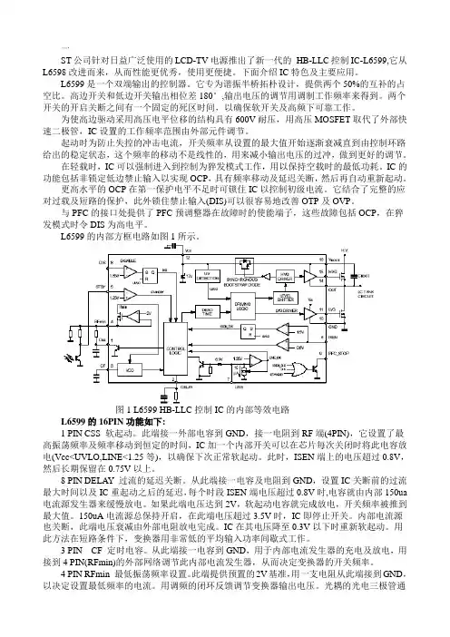
一ST公司针对日益广泛使用的LCD-TV电源推出了新一代的HB-LLC控制IC-L6599,它从L6598改进而来,从而性能更优秀,使用更便捷。
下面介绍IC特色及主要应用。
L6599是一个双端输出的控制器。
它专为谐振半桥拓朴设计,提供两个50%的互补的占空比。
高边开关和低边开关输出相位差180°,输出电压的调节用调制工作频率来得到。
两个开关的开启关断之间有一个固定的死区时间,以确保软开关及高频下可靠工作。
为使高边驱动采用高压电平位移的结构具有600V耐压,用高压MOSFET取代了外部快速二极管,IC设置的工作频率范围由外部元件调节。
起动时为防止失控的冲击电流,开关频率从设置的最大值开始逐渐衰减直到由控制环路给出的稳定状态,这个频率的移动不是线性的,用来减小输出电压的过冲,做到更好的调节。
在轻载时,IC可以强制进入到控制为猝发模式工作,用以保持空载时的最低功耗。
IC的功能包括非锁定低边禁止输入以实现OCP,具有频率移动及延迟关断,然后再自动重新起动。
更高水平的OCP在第一保护电平不足时可锁住IC以控制初级电流。
它结合了完整的应对过载及短路的保护,此外锁住禁止输入(DIS)可以很容易地改善OTP及OVP。
与PFC的接口处提供了PFC预调整器在故障时的使能端子,这些故障包括OCP,在猝发模式时令DIS为高电平。
L6599的内部方框电路如图1所示。
图1 L6599 HB-LLC控制IC的内部等效电路L6599的16PIN功能如下:1 PIN CSS 软起动。
此端接一外部电容到GND,接一电阻到RF端(4PIN),它设置了最高振荡频率及频率移动到恒定的时间,IC加一个内部开关可以在芯片每次关闭时将此电容放电(Vcc<UVLO,LINE<1.25等),以确保下次正常软起动。
此时,ISEN端上的电压超过0.8V,然后长期保留在0.75V以上。
8 PIN DELAY 过流的延迟关断。
从此端接一电容及电阻到GND,设置IC关断前的过流最大时间以及IC重起动之后的延迟,每个时段ISEN端电压超过0.8V时,电容就由内部150ua 电流源发生器来缓慢放电。
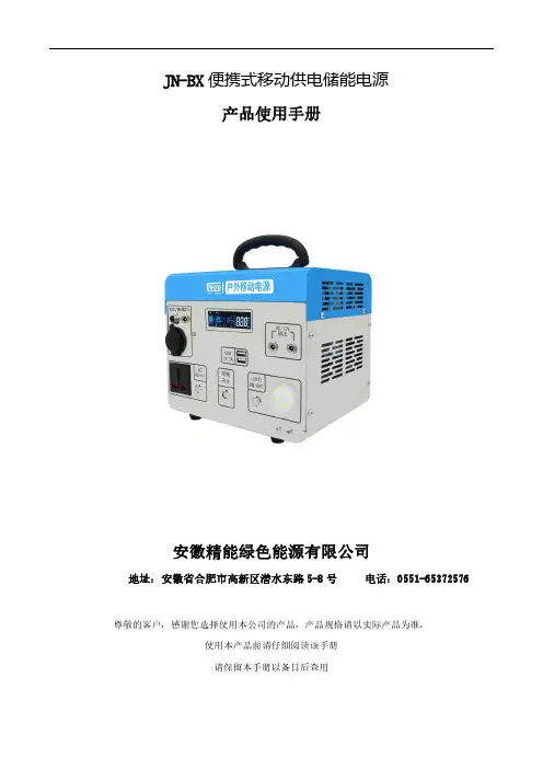
JN-BX便携式移动供电储能电源产品使用手册安徽精能绿色能源有限公司地址:安徽省合肥市高新区潜水东路5-8号尊敬的客户,感谢您选择使用本公司的产品,产品规格请以实际产品为准,使用本产品前请仔细阅读该手册请保留本手册以备日后查用目录一产品特点 (2)1.1产品概述 (2)1.2产品特点 (2)二产品介绍 (3)2.1产品的尺寸图 (3)2.2面板介绍 (4)2.3显示屏介绍 (5)三操作说明 (6)3.1产品充电口介绍 (6)3.2产品输出口介绍 (7)四注意事项 (8)4.1使用技巧 (8)4.2安全与维护 (9)4.3故障排除 (9)4.4系统维护 (10)五保修承诺 (11)六设备参数 (11)七装箱清单及通信方式模块附件选配 (13)八安装尺寸 (14)一产品特点1.1产品概述非常感谢您使用本公司生产的多功能便携式移动供电储能电源产品。
这款产品功能非常的多,如果遇到停电,或者外出旅行需要用电,您可以使用该产品为您的电器或数码产品供电。
本电源内置高品质锂离子电池,支持DC、USB直流电输出,AC交流电输出。
使用本产品前,请认真阅读本用户手册,并妥善保存,以备查阅。
此手册用于帮助您正确地使用本产品,有关产品的配置情况,请查阅与本产品相关的合约(若有),或咨询向您出售产品的经销商。
本手册中的图片仅供参考,如果有个别图片与产品实物不符,请以产品实物为准。
1.2产品特点1.支持AC、DC、USB多种输出方式;2.内置LED照明灯,夜间应急高亮度;3.具有市电、车载、太阳能三种充电方式;4.此产品体积小,重量轻,效率高,性能稳定;5.本电源内置高品质磷酸铁锂电池,持久续航;6.本电源内置纯正弦波逆变器,稳定的交流输出;7.智能彩屏显示,可以准确显示系统的工作状态;8.具有过压、欠压、短路、过温、反接等多重保护;二产品介绍2.1产品的尺寸图参数名称质量尺寸型号JN-BX500/55-12JN-BX1000/100-12JN-BX1500/150-12JN-BX2000/150-12重量(kg)产品尺寸225*175*205mm280*228*233mm340*245*326mm340*245*326mm L*D*H(mm)2.2面板介绍表2-1接口功能介绍按键/接口作用备注AC ON/OFF 按AC开关,可实现AC输出,需要关闭时,再按下AC开关,可以实现AC输出关闭;控制开关打开控制开关,显示屏亮,可以使用DC直流输出,也可进行充电,不使用时再按下进行关闭;LED ON/OFF 按LED开关,可实现照明,需要关闭时,再按下LED开关,进行关闭;DC 充电口此接口是多选,必须打开控制开关才可使用,可连接太阳能板、市电、车载充电;注意正负极DC/12V输出12V直流电的输出口;USB5V/2A5V USB输出口,最大输出电流2A;2.3显示屏介绍表2-2图标功能介绍表2-3字段功能介绍字段名称定义功能说明Ubat蓄电池电压字段亮起,在数据显示区显示当前蓄电池电压Upv充电电压字段亮起,在数据显示区显示当前充电端的电压Icharge 充电电流字段亮起,在数据显示区显示当前蓄电池充电电流Pcharge充电功率字段亮起,在数据显示区显示蓄电池充电功率Uload 逆变电压字段亮起,在数据显示区显示当前逆变器输出电压Freq逆变频率字段亮起,在数据显示区显示逆变器交流电频率Pload放电功率字段亮起,在数据显示区显示蓄电池放电功率Temp 散热器温度字段亮起,在数据显示区显示当前充电状态下散热器温度ERROR报警指示当有故障的时候,该字段亮起图标名称定义功能说明负载图标亮起表示交流负载有输出充电显示图标亮起表示检查到充电端有电压电池电量图标亮起表示电池接入,其内部表示电池电量状态图标图标亮起并滚动分别表示充电状态和放电状态故障图标图标闪烁表示系统有故障情况发生三操作说明3.1产品充电口介绍市电充电:将本产品标配的充电适配器的AC交流电接头连接至家用AC交流电插座,将标配充电器DC连接头接入本产品DC输入接口,此时光伏板图标将亮起,跑马箭头跑动起来,表示本产品的正常充电。

信息中心UPS技术建议书VER100301长沙泰和英杰系统集成工程有限责任公司二O一O年四月目录一、系统设计规划21.1 系统概述21.2 系统设计依据31.3 系统设计原则及系统特点3二、UPS设计方案42.1 概述42.2 UPS供配电系统42. 3 艾默生Adapt 模块化UPS系统52. 4 蓄电池系统9一、系统设计规划1.1 系统概述随着电子计算机在国防、科研、生产自动化、管理等领域的广泛应用,近二十几年里在我国如雨后春笋般地建成了很多大、中、小各种规模的计算机机房,为计算机寻求和建造一个合适的工作环境以确保计算机可靠,充分发挥其设计性能,延长机器的使用寿命以及确保工作人员身心健康的问题越来越受到建设方的重视,并成为追求目标。
艾默生网络能源具有业界最齐全的网络能源产品线、并且其网络能源主设备全部为自有品牌。
艾默生网络能源利用自身强大的技术优势,为客户提供端到端的一体化解决方案,这样降低了客户选型、采购、工程管理的整体成本,大幅度提高工程建设速度,缩短工程周期,加快机房投产,统一和缩小客户的维护工作界面,这样有助于客户专注于核心业务,提高客户的核心竞争力。
1.2系统设计依据本项目将依据国家标准及行业标准设计和管理施工,所引用的文件及标准包括:1.业主提供的建设资料2.施工现场条件和勘测资料3.相关国家标准及规范文件:GB50174-2008《电子信息系统机房设计规范》GB 50462-2008《电子信息系统机房施工及验收规范》GB 50019-2003《采暖通风与空气调节设计规范》GB 50243-2002《通风与空调工程施工质量验收规范》GB 50311-2007《综合布线系统工程设计规范》GB 50312-2007《综合布线系统工程验收规范》GB/T 50314-2006《智能建筑设计标准》JGJ 16-2008《民用建筑电气设计规范》GB 50052-95《供配电系统设计规范》GB 50303-2002《建筑电气工程施工质量验收规范》YD5040-2005《通信电源设备安装工程设计规范》YD5098-2005《通信局(站)防雷与接地工程设计规范》GB50057-2000《建筑物防雷设计规范》GB50343-2004《建筑物电子信息系统防雷技术规范》GB 50370-2005《气体灭火系统设计规范》1.3系统设计原则及系统特点本系统集交流不间断供配电系统整体解决方案。
Eaton PDG33K0600P9MJPower Defense Globally Rated, Frame 3, Three Pole, 600A, 50kA/480V, PXR25 LSIG Motor Protection w/ Modbus RTU and Relays, Std Line Load Term (PDG3X3TA630)Eaton Power Defense molded case circuit breakerPDG33K0600P9MJ 786679350232109.1 mm 257.1 mm 138.9 mm 5.92 kg Eaton Selling Policy 25-000, one (1) year from the date of installation of theProduct or eighteen (18) months from thedate of shipment of the Product,whichever occurs first.RoHS Compliant CCC MarkedCSAIEC 60947-2UL 489Product NameCatalog Number UPCProduct Length/Depth Product Height Product Width Product Weight WarrantyCompliancesCertificationsModbus / relays50 kAIC at 480 Vac3600600 AThree-pole600 VPD3 Global10 kAIC Icu @250 Vdc85 kAIC @240V (UL) ElectronicClass AComplete breakerStandard Line and Load600 VacPXR 25 Motor Protection LSIG Modbus RTU Eaton Power Defense MCCB PDG33K0600P9MJ 3D drawingConsulting application guide - molded case circuit breakersPower Xpert Protection Manager x64StrandAble terminals product aidPower Defense technical selling bookletPower Defense molded case circuit breaker selection posterPower Defense brochurePower Xpert Release trip units for Power Defense molded case circuit breakersMolded case circuit breakers catalogPDG3 CSA certification 100-400aPDG3B 450A-600A CB reportPDG3 UL authorization 250-600a PXRPDG3 UL authorization 100-400aPDG3 CSA certification 250-600aPDG3 45-400A CB reportPDG3 UL authorization 250-600a TMTUEU Declaration of Conformity - Power Defense molded case circuit breakersPower Defense Frame 3 interphase barrier - IL012229EN H03Power Defense Frame 1-2-3-4 IP door barrier assembly instructions -IL012278ENPower Defense Frame 3 shunt trip UVR instructions - IL012140EN Power Defense Frame 3 adapter kit installation instructions LZM3 to PD3 - IL012227ENPower Defense Frame 3 extendable shaft rotary handle mech -IL012112ENPower Defense Frame 3 trip unit replacement instructions - IL012157EN Power Defense Frame 3 finger protection assembly installation instructions - IL012279ENPower Defense Frame 3 reverse feed connector kit Cat NumPDG3X3(2)(4)TA400HRF instructions - IL012252ENSpecial featuresInterrupt ratingFrameRated operation voltage (Ue) at AC - max Amperage RatingNumber of polesVoltage rating - maxCircuit breaker typeInterrupt rating rangeSwitch off techniqueClassCircuit breaker frame typeTerminalsVoltage ratingTrip TypeCommunication 3D CAD drawing package Application notes BrochuresCatalogsCertification reports Installation instructionsPower Defense Frame 3 reverse feed connector kit Cat NumPDG3X3(2)(4)TA630RF instructions - IL012253ENPower Defense Frame 3 box terminal installation instructions -IL012299ENPower Defense Frame 3 screw terminal_end cap kit, 400A, 3 pole –IL012262ENPower Defense Frame 3 terminal cover assembly instructions -IL012281ENPower Defense Frame 3 terminal kit Cat Num PDG3X3(2)(4)TA400RF instructions - IL012251ENPower Defense Frame 3 multi wire connector kit -PDG3X3(2)(4)TA4006W and PDG3X3(2)(4)TA4003W instructions-IL012247EN H01Power Defense Frame 3 Direct Rotary Handle Assy With Interlock Version Instructions (IL012139EN).pdfPower Defense Frame 4 shunt trip UVR instructions - IL012129EN Power Defense Frame 3 Aux, Alarm, ST and UVR Animated Instructions.rh Power Defense Frame 3 rear connection installation instructions -IL012300ENPower Defense Frame 3 plug-in adapter installation instructions -IL012311ENPower Defense Frame 3 screw terminal end cap kit 600A, 3 pole -IL012264ENPower Defense Frame 3 Breaker Instructions (IL012107EN).pdfPower Defense Frame 2/3/4/5/6 voltage neutral sensor module wiring instructions – IL012316ENPower Defense Frame 3 terminal spreader assembly instructions -IL012301ENPower Defense Frame 3 locking devices and handle block instructions - IL012150ENPower Defense Frame 3 handle mech direct rotary handle instructions - IL012111ENPower Defense Frame 4 locking devices and handle block instructions - IL012151ENPower Defense Frame 3 interphase barriers 3-pole - IL012229EN H01 Power Defense Frame 4 reverse feed connector kit instructions for PDG4X3(2)(4)TA800RF instructions - IL012254ENPower Defense Frame 3 multi-tap terminal kit Cat NumPDG3X3(2)(4)TA6006W Instructions - IL012248ENPower Defense Frame 3 multi-tap terminal kit Cat NumPDG3X3(2)(4)TA6006WSW instructions - IL012250ENInstallation videosPower Defense Frame 3 Handle Mech Direct Rotary Handle AnimatedInstructions.rhPower Defense Frame 3 trip unit replacement animated instructions.rh Power Defense Frame 3 Handle Mech Variable Depth Rotary Handle Animated Instructions.rhPower Defense Frame 3 Shunt Trip_UVR Animated Instructions.pdf.rh Power Defense Frame 3 Locking Devices and Handle Block Animated Instructions.pdf.rhMultimediaPower Defense Frame 3 Aux, Alarm, Shunt Trip, and UVR How-To Video Power Defense Frame 3 Direct Rotary Handle Mechanism Installation How-To VideoPower Defense Frame 3 Trip Unit Installation How-To VideoPower Defense molded case circuit breakersPower Defense Frame 2 Variable Depth Rotary Handle Mechanism Installation How-To VideoEaton Power Defense for superior arc flash safetyPower Defense Frame 6 Trip Unit How-To VideoPower Defense Frame 5 Trip Unit How-To VideoPower Defense Frame 3 Variable Depth Rotary Handle Mechanism Installation How-To VideoPower Defense BreakersSpecifications and datasheetsEaton Specification Sheet - PDG33K0600P9MJTime/current curvesPower Defense time current curve Frame 3 - PD3White papersSingle and double break MCCB performance revisitedIntelligent circuit protection yields space savingsImplementation of arc flash mitigating solutions at industrial manufacturing facilitiesIntelligent power starts with accurate, actionable dataMolded case and low-voltage power circuit breaker healthMaking a better machineMolded case and low-voltage breaker healthSafer by design: arc energy reduction techniquesEaton Corporation plc Eaton House30 Pembroke Road Dublin 4, Ireland © 2023 Eaton. All Rights Reserved. Eaton is a registered trademark.All other trademarks areproperty of their respectiveowners./socialmedia。
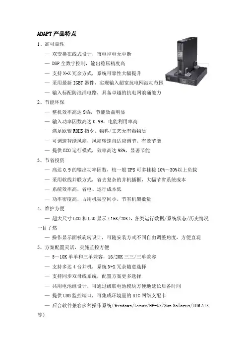
ADAPT产品特点1、高可靠性—双变换在线式设计,市电掉电无中断— DSP全数字控制,输出稳压精度高—支持N+X冗余方式,系统可靠性大幅提升—采用最新IGBT器件,实现输入超宽抗电网波动范围—输入标配防浪涌电路,具备卓越的抗电网浪涌能力2、节能环保—整机效率高达94%,节能效益明显—输入功率因数高达0.99,电能利用率高—满足欧盟ROHS指令,物料/工艺无有毒物质—可调速智能风扇,风扇转速自适应调节,有效节能—提供ECO运行模式,效率高达98%,显著节能3、节省投资—高达0.9的输出功率因数,较一般UPS可多挂接10%~30%以上负载—采用软线并联方式,省去复杂的并机插框,大幅节省系统成本—系统效率高,省电、运行成本低—功率密度高,占用机架空间小,节省机架数量4、维护方便—超大尺寸LCD和LED显示(16K/20K),各类运行数据/系统状态/历史情况一目了然—操作显示面板旋转设计,可随安装方式不同自由调整角度,方便直观5、方案配置灵活,实施监控方便— 5~10K单单和三单兼容,16/20K三三/三单兼容—支持多达4台并机,系统N+X冗余随意选择—支持同步双母线系统,配置方案更多选择—共用电池组设计,可通过级联电池模块方便地延长后备时间—提供USB监控端口,可集成环境量的SIC网络支配卡—后台软件兼容多种操作系统(Windows/Linux/HP-UX/Sun Solarus/IBM AIX 等)—兼容艾默生机房监控平台SiteMonitor,支持Web监控及服务器自动安全关机功能—提供Mib库,方便接入各类NMS系统6、保护及延长电池组寿命—超宽输入电压/频率范围,有效减少电池放电几率,延长寿命—具备温度补偿功能,减少环境温度对电池寿命的影响—超强充电能力,有效缩短电池回充时间—电池组节数设置灵活,便于电池系统的调节(16/20KVA)—支持共用电池组(16/20KVA),节省电池投资技术参数表。
目录一、前言 (1)二、BND系列产品简介 (3)三、BND系列产品型号说明 (4)四、BND系列产品技术原理及性能指标 (6)五、BND系列产品使用方法 (7)六、售后服务 (11)附件 (12)一、前言1.1概述逆变电源就是将直流电能转换成交流电能的装置,供交流负载用电。
传统的逆变电源是采用直流电动机—交流发电机组来实现这种电能转换的,而现代的逆变电源多是通过功率半导体器件来实现电能转换的,又被称为静止变流器。
其在体积、重量、变换效率、可靠性、电性能等方面的优越性都大大超过了传统的逆变装置。
正弦波逆变电源作为新一代直流/交流逆变电源已广泛用于电力、通信、金融、铁路、工业控制、医疗、军事等各个重要领域,输出稳定可靠,可由直流系统保证能源并长期连续供电,消除了直接使用市电带来的供电中断、电压不稳,杂音干扰和雷电侵入等不利因素。
同时克服了小型UPS供电时间短的致命缺陷,确保用电设备安全可靠。
本公司生产的正弦波逆变电源包括电力专用逆变电源、通信专用逆变电源、车载专用逆变电源、机车专用逆变电源、光伏专用逆变电源等,均采用进口高速开关功率器件,使用CPU集成控制技术,数字化电路,可靠性强,在线长年运行,不受时间限制,将直流电源转换、稳压、隔离、输出单相AC220V或三相AC380V、50Hz正弦波纯净交流电,对负载不间断供电,使负载不受电网各种干扰,保持正常运行。
BND系列电力专用正弦波逆变电源系经过严密的生产控制及品质管制与精确之测试和校证,能够为用户提供高品质的服务。
正确安装和使用本产品能更好发挥其作用,因此在安装和使用前应认真阅读用户手册。
对本手册和产品上的说明事宜及注意事项应特别注意。
1.2 使用须知本产品在保修期间一年内,任何正常使用状况下之自然损坏,由本公司免费负责修护,但若有下列任一情况者,则不在保修之列:(1)非经本公司允许,擅自进行维修而损坏。
(2)用简单调压器加整流桥测试本电源。
(因低压或超高压窜入,易使电源不稳或烧坏器件。
nsa zcut-9说明书
产品概述:
品牌:NSA
型号:ZCUT-9
电源类型:交流电源
电源电压:100V.120V.220-240VV
功率:24(W)
规格:116mm(w)*140mm(H)*213mm(D)
适用范围:保护膜、透明胶带、高温胶带、透明胶带、美纹纸胶等重量2.5(kg)产品技术参数:
剪裁长度:5 - 999 mm
剪裁宽度:6 - 60 mm
送料速度:200mm/秒(使用工艺胶带)
胶带最大外径:300 mm
附件:电源线、2A保险丝(内置插口)、分离器、导向板、镊子,刀片润滑油
机身材质:防静电ABS
额定:AC100V 50/60Hz
性能特点:
1.存储记忆功能
2.三段循环剪切功能,也可以设置为一段或者两段循环剪切
3.压力自动调整
4.LED数字显示剪切长度
5.精确度高,误差在±0.5mm以内
6.剪切速度快
7.拆装胶纸更为方便
8.胶纸自动对中功能
9.可同时剪切两卷胶纸
优点:
1.、快速,提高效率
2、准确,节省胶纸胶带
3、美观,切割口平整,美观大方
4、节省劳动力。