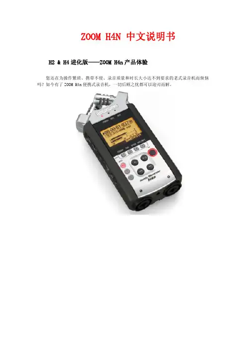
280转换工具说明书
- 格式:docx
- 大小:2.42 MB
- 文档页数:13
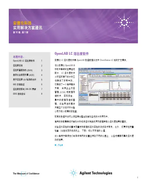
安捷伦科技实用解决方案通讯本期内容:OpenLAB LC 溶出度软件溶出度交流溶出杯直接加热 (DVH)自动化合规性引擎 (ACE)用于溶出度 UV 检测的光纤MQ 文档验证溶出度资质与 280-DS 更新DDG 在线会议12345678第 2 页继续OpenLAB LC 溶出度软件安捷伦 LC 溶出度软件是 OpenLAB 色谱数据系统中 ChemStation LC 版的扩充模块。
作为安捷伦 OpenLAB 分析软件套装的主要组成部分,LC 溶出度软件为可控环境下的分析工作提供了所有手段。
它提供了一个通用解决方案,采用企业内容管理 (ECM) 或数据存储软件,实现安全、集中的数据存储和管理。
这些灵活的解决方案正广泛运行于大型公司及较小规模的实验室。
现有的色谱方法可以很容易地整合到自动生成的分析序列中。
通用的参数集是运行自动分析和将溶出样品的序列数据转换为溶出度结果的基础。
这些溶出实验的设置与定量药物数据和溶出实验的测试条件有关。
此外,还要评估质量检查(如在设定时间点的上、下限)和认可标准的 Q 值。
这一通用方案使我们能够将相同的设置应用到不同的仪器上,以生成精确可靠的溶出度测试结果。
12OpenLAB:续其设置可依据药典方法进行,且适用于手动和全自动采集的溶出样品。
这些设置与经过验证的 LC 方法相结合,可方便地适用于使用不同仪器的不同实验室。
为满足分析要求,所有安捷伦 LC 色谱系列设备均可控制。
OpenLAB LC ChemStation软件提供了一种控制集成的 LC 系统中各种不同模块的手段。
而且,带 ISET 的新型 1290 Infinity LC 系统具有对不同设备(包括安捷伦 LC 模块和其它供应商仪器)的模拟功能,极大提高了系统的灵活性。
无需额外的验证步骤,即可将现有 LC 方法整合到我们的溶出度实验设置中。
新的系统可以实现更快速、更简便的溶出度分析。
使用内置的方法向导可轻松设置控制溶出样品分析的参数。
视频转换工具Media Player Utilities5.24_02操作指南
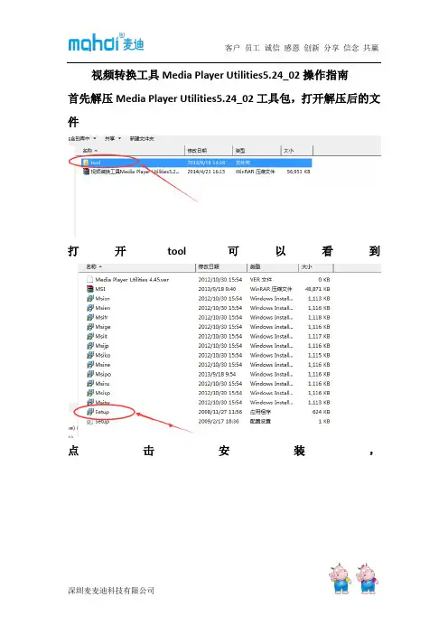
首先解压Media Player Utilities5.24_02工具包,打开解压后的文件
打开tool可以看到
点击安装,
点击下一步,一直点击下一步等到
提示安装完成
有些
电脑会提示安装驱动
,完成了之后,打开路径在电脑左下角的位置点击:
开始-----所有程序
——媒体播放器管理工具 4.45选择AMV&AVI视频转换工具点击运行
如图;
找到需要转换的视频目录,在输入文件夹里边找
图:
,选择需要转换的视频文件,然后在设置里边调分辨率,先在选择的文件哪里把
钩去掉再打一下,打了之后,打完之后可以看到设置图标变色
在设置里边调分辨率160*128
点击确定,选着箭头开始转换开始转换
装换完成的文件在输出文件夹里边找路径。
Selection Guide 2:1 2W OutputMODEL NUMBER INPUTVOLTAGE(VDC)OUTPUTVOLTAGE(VDC)OUTPUTCURRENT(mA)INPUT6CURRENT(mA) EFF(%)7ISOLATION8(VDC)PACKAGEFULLLOADNOLOADPM22-01(-3K) 4.5-9 3.3 500 465 50 71 1500(3000) H PM22-02(-3K) 4.5-9 5 400 555 50 72 1500(3000) H PM22-03(-3K) 4.5-9 9 222 519 50 77 1500(3000) H PM22-04(-3K) 4.5-9 12 150 480 50 75 1500(3000) H PM22-05(-3K) 4.5-9 15 120 456 50 79 1500(3000) H PM22-06(-3K) 9-18 3.3 500 205 30 67 1500(3000) H PM22-07(-3K) 9-18 5 400 219 20 76 1500(3000) H PM22-08(-3K) 9-18 9 222 225 20 74 1500(3000) H PM22-09(-3K) 9-18 12 168 209 20 80 1500(3000) H PM22-10(-3K) 9-18 15 133 209 20 80 1500(3000) H PM22-11(-3K) 9-18 24 83 213 20 78 1500(3000) H PM22-12 9-18 +/-5 +/-200 225 20 74 1500 H PM22-13 9-18 +/-12 +/-83 225 20 74 1500 H PM22-14 9-18 +/-15 +/-67 225 20 74 1500 H PM22-15(-3K) 18-36 3.3 500 93 12 74 1500(3000) H PM22-16(-3K) 18-36 5 400 110 12 76 1500(3000) H PM22-17(-3K) 18-36 9 222 111 13 75 1500(3000) H PM22-18(-3K) 18-36 12 168 104 11 80 1500(3000) H PM22-19(-3K) 18-36 15 133 105 11 79 1500(3000) H PM22-20(-3K) 18-36 24 83 107 11 78 1500(3000) H PM22-21 18-36 +/-5 +/-200 112 12 74 1500 H PM22-22 18-36 +/-12 +/-83 112 12 74 1500 H PM22-23 18-36 +/-15 +/-67 112 12 74 1500 H PM22-24(-3K) 36-75 3.3 500 46 8 75 1500(3000) H PM22-25(-3K) 36-75 5 400 56 8 74 1500(3000) H PM22-26(-3K) 36-75 9 222 55 8 75 1500(3000) H PM22-27(-3K) 36-75 12 168 51 8 82 1500(3000) H PM22-28(-3K) 36-75 15 133 51 8 82 1500(3000) H PM22-29(-3K) 36-75 24 83 54 8 77 1500(3000) H PM22-30 36-75 +/-5 +/-200 56 8 74 1500 H PM22-31 36-75 +/-12 +/-83 54 8 77 1500 H PM22-32 36-75 +/-15 +/-67 54 8 77 1500 H Note: Other input to output voltages may be available. Please contact factory.FOR EXAMPLE: PM22-12(H PACKAGE 2W SINGLE OUTPUT 1500VDC ISOLATION)PM22-11(-3K)(H PACKAGE 2W SINGLE OUTPUT 3000VDC ISOLATION)6NOMINAL INPUT VOLTAGE.7 NOMINAL INPUT VOLTAGE, FULL LOAD.Selection Guide 2:1 2W OutputMODEL NUMBERINPUTVOLTAGE(VDC)OUTPUTVOLTAGE(VDC)OUTPUTCURRENT(mA)INPUT9CURRENT(mA) EFF(%)10ISOLATIO N11(VDC)PACKAGEFULLLOADNOLOADPM22-33 4.5-9 3.3 500 465 50 71 1500 J PM22-34 4.5-9 5 400 555 50 72 1500 J PM22-35 4.5-9 9 222 519 50 77 1500 J PM22-36 4.5-9 12 150 500 50 72 1500 J PM22-37 4.5-9 15 120 500 50 72 1500 J PM22-389-18 3.3 500 205 30 67 1500 J PM22-399-18 5 400 219 20 76 1500 J PM22-409-18 9 222 225 20 74 1500 J PM22-419-18 12 168 213 20 78 1500 J PM22-429-18 15 133 213 20 78 1500 J PM22-439-18 24 83 213 20 78 1500 J PM22-4418-36 3.3 500 93 12 74 1500 J PM22-4518-36 5 400 112 12 74 1500 J PM22-4618-36 9 222 111 13 75 1500 J PM22-4718-36 12 168 107 11 78 1500 J PM22-4818-36 15 133 107 11 78 1500 J PM22-4918-36 24 83 107 11 78 1500 J PM22-5036-75 3.3 500 52 8 67 1500 J PM22-5136-75 5 400 56 8 74 1500 J PM22-5236-75 9 222 55 8 75 1500 J PM22-5336-75 12 168 51 8 82 1500 J PM22-5436-75 15 133 51 8 82 1500 J PM22-5536-75 24 83 54 8 77 1500 J Note: Other input to output voltages may be available. Please contact factory.9NOMINAL INPUT VOLTAGE.10 NOMINAL INPUT VOLTAGE, FULL LOAD.Selection Guide 4:1 2W OutputMODEL NUMBERINPUTVOLTAGE(VDC)OUTPUTVOLTAGE(VDC)OUTPUTCURRENT(mA)INPUT12CURRENT(mA) EFF(%)13ISOLATION14(VDC)PACKAGEFULLLOADNOLOADPM24-01(-3K) 9-36 3.3 500 205 30 70 1500(3000) H PM24-02(-3K) 9-36 5 400 222 20 74 1500(3000) H PM24-03(-3K) 9-36 9 222 225 20 74 1500(3000) H PM24-04(-3K) 9-36 12 165 213 20 78 1500(3000) H PM24-05(-3K) 9-36 15 133 213 20 78 1500(3000) H PM24-06(-3K) 9-36 24 83 213 20 78 1500(3000) H PM24-07 9-36 +/-15 +/-67 220 20 76 1500 H PM24-08(-3K) 18-75 3.3 500 98 12 70 1500(3000) H PM24-09(-3K) 18-75 5 400 112 12 74 1500(3000) H PM24-10(-3K) 18-75 9 222 112 13 74 1500(3000) H PM24-11(-3K) 18-75 12 165 107 11 78 1500(3000) H PM24-12(-3K) 18-75 15 133 107 11 78 1500(3000) H PM24-13(-3K) 18-75 24 83 107 11 78 1500(3000) H Note: Other input to output voltages may be available. Please contact factory.12NOMINAL INPUT VOLTAGE.13 NOMINAL INPUT VOLTAGE, FULL LOAD.Selection Guide (4) 2:1 3W OutputMODEL NUMBERINPUTVOLTAGE(VDC)OUTPUTVOLTAGE(VDC)OUTPUTCURRENT(mA)INPUT15CURRENT(mA) EFF(%)16ISOLATION17(VDC)PACKAGEFULLLOADNOLOADPM32-01(-3K) 4.5-9 3.3 700 641 100 72 1500(3000) H PM32-02(-3K) 4.5-9 5 600 800 100 75 1500(3000) H PM32-03(-3K) 4.5-9 9 333 778 100 77 1500(3000) H PM32-04(-3K) 4.5-9 12 250 779 100 77 1500(3000) H PM32-05(-3K) 4.5-9 15 200 779 100 77 1500(3000) H PM32-06 4.5-9 +/-5 +/-300 789 100 76 1500 H PM32-07 4.5-9 +/-12 +/-125 779 100 77 1500 H PM32-08 4.5-9 +/-15 +/-100 779 100 75 1500 H PM32-09(-3K) 9-18 3.3 700 263 45 73 1500(3000) H PM32-10(-3K) 9-18 5 600 336 45 74 1500(3000) H PM32-11(-3K) 9-18 9 333 320 45 78 1500(3000) H PM32-12(-3K) 9-18 12 250 320 45 78 1500(3000) H PM32-13(-3K) 9-18 15 200 310 45 81 1500(3000) H PM32-14 9-18 +/-5 +/-300 324 45 77 1500 H PM32-15 9-18 +/-12 +/-125 320 45 78 1500 H PM32-16 9-18 +/-15 +/-100 320 45 78 1500 H PM32-17(-3K) 18-36 3.3 700 128 20 75 1500(3000) H PM32-18(-3K) 18-36 5 600 162 20 77 1500(3000) H PM32-19(-3K) 18-36 9 333 152 20 82 1500(3000) H PM32-20(-3K) 18-36 12 250 158 20 79 1500(3000) H PM32-21(-3K) 18-36 15 200 154 20 81 1500(3000) H PM32-22 18-36 +/-5 +/-300 162 20 77 1500 H PM32-23 18-36 +/-12 +/-125 158 20 79 1500 H PM32-24 18-36 +/-15 +/-100 158 20 79 1500 H PM32-25(-3K) 36-75 3.3 700 66 12 73 1500(3000) H PM32-26(-3K) 36-75 5 600 81 12 77 1500(3000) H PM32-27(-3K) 36-75 9 333 80 12 78 1500(3000) H PM32-28(-3K) 36-75 12 250 79 12 79 1500(3000) H PM32-29(-3K) 36-75 15 200 76 12 82 1500(3000) H PM32-30(-3K) 36-75 24 125 79 12 79 1500(3000) H PM32-31 36-75 +/-5 +/-300 81 12 77 1500 H PM32-32 36-75 +/-12 +/-125 79 12 79 1500 H PM32-33 36-75 +/-15 +/-100 79 12 79 1500 H15NOMINAL INPUT VOLTAGE.16 NOMINAL INPUT VOLTAGE, FULL LOAD.Input Fuse Selection Guide4.5-9VINPUT VOLTAGE(VDC) 9-18V(9-36V) INPUT VOLTAGE(VDC) 18-36V(18-75V) INPUT VOLTAGE(VDC)36-75V INPUT VOLTAGE(VDC) 2000mA Slow-Blow Type1000mA Slow-Blow Type500mA Slow-Blow Type 200mA Slow-Blow TypeNote: Certain applications may require the installation of external fuse in front of the input.EPM 2-3 Watt Series Application Notes: EXTERNAL CAPACITANCE REQUIREMENTS:No external capacitance is required for operation of the EP 2-3 Watt series.To meet the reflected ripple requirements of the converter, an input impedance of less than 0.5 ohm from DC to 100KHz is required.External output capacitance is not required for operation, however it is recommended that 10uF tantalum and 0.1uF ceramic DC-DCCONVERTER+Vin-Vin+Vout-VoutOUTPUTINPUT。
LoLa280Professionalmultichannel sound cardUser manual2For technical support,please contact your supplierDigigram S.A.82/84 Allée Galilée, 38330 Montbonnot-Saint-Martin, FRANCETel:+33(0)476524747•Fax:+33(0)476521844•E-mail:*****************Digigram Inc.2000 North 14th Street - Suite 530, Arlington, VA 22201, USA Tel:+17038759100•Fax:+17038759161•E-mail:******************Digigram Asia Pte Ltd.60 Albert Street - #19-11OG Albert Complex Singapore 189969, Singapore Tel:+6562912234•Fax:+6562913433•E-mail:**********************LoLa280User manual 3Table of ContentsINFORMATION FOR THE USER .............................................................................................4 IMPORTANT NOTICE .......................................................................................................................5 CONTENTS OF THIS PACKAGE .............................................................................................5 FEATURES .. (6)Main hardware features (6)Main software features............................................................................................................................6 MINIMUM REQUIREMENTS . (6)Hardware requirements (6)Software requirements (7)OS supported...............................................................................................................................................7 HARDWARE INSTALLATION (7)Installing the card (7)Interrupt and memory address..............................................................................................................7 SOFTWARE INSTALLATION (7)Installation under Windows XP, Windows Server 2003,Windows Server 2008, Windows Vista, and Windows 7 (8)The ASIO control panel (9)The ‘Digigram LoLa Manager’ control panel (10)Removing the driver under Windows XP and Windows Server 2003 (11)Removing the driver under Windows Vista, Windows Server 2008, and Windows 7.......11 HOW TO CHECK THE INSTALLATION ........................................................................12 SPECIFICATIONS .. (16)Configuration (16)Inputs (16)Outputs (17)Connectors (17)Audio specifications (17)Analog audio performance (18)Development environments....................................................................................................18 APPENDIX A: SCHEMATIC DIAGRAM .. (19)LoLa280 Schematic Diagram (19)Layout............................................................................................................................................19 APPENDIX B: CABLES (20)LoLa280 analog I/O cable (20)Wiring Diagram – analog cable LoLa280 (21)LoLa280 cable pinout...............................................................................................................22 APPENDIX C: BRACKET (23)Replacing the bracket............................................................................................................................23 Copyright 2008 – 2010 Digigram. All rights reserved. No portion of this manual may be reproduced without prior written consent from Digigram. The copyright protection claimed here includes photocopying, translation and/or reformatting of the information contained in this manual. While every effort has been made to ensure accuracy, Digigram is not responsible for errors and omissions, and reserves the right to make improvements or changes in the products and programs described without notice. Digigram, the Digigram logo, and LoLa280 are registered trademarks or trademarks of Digigram S.A.. All other trademarks are property of their respective holders.4 INFORMATION FOR THE USERThis device complies with part 15 of FCC rules. Operation is subject to the following two conditions: (1) This device may not cause harmful interference, and (2) This device must accept any interference received, including interference that may cause undesired operation. This equipment has been tested and found to comply with the limits for a CLASS B digital device, pursuant to Part 15 of the FCC Rules. These limits are designed to provide reasonable protection against harmful interference in a residential installation. This equipment generates, uses, and can radiate radio frequency energy and, if not installed and used in accordance with the instructions contained in this data sheet, may cause harmful interference to radio and television communications. However, there is no guarantee that interference will not occur in a particular installation. If this equipment does cause harmful interference to radio or television reception, which can be determined by turning the equipment off and on, the user is encouraged to try to correct the interference by one or more of the following measures:* reorient or relocate the receiving antenna* increase the separation between the equipment and the receiver* connect the equipment into an outlet on a circuit different from that of the receiver * consult the dealer or an experienced audio television technician.Note: Connecting this device to peripheral devices that do not comply with CLASS B r equirements or using an unshielded peripheral data cable could also result in h armful interference to radio or television reception. The user is cautioned t hat any changes or modifications not expressly approved by the party r esponsible f or compliance could void the user’s authority to operate this equipment. To ensure that the use of this product does not contribute to interference, it is necessary to use shielded I/O cables.Warning:Electrostatic discharge (ESD) can damage severalcomponents on the board. To avoid such damage inhandling the board, take the following precautions:Bring the device and everything that contacts it to ground potential by providing a conductive surface and discharge paths. As a minimum, observe these precautions:•Disconnect all power and signal sources. •Place the device on a grounded conductive work surface. •Ground yourself via a grounding wrist strap or by holding a grounded object. • Ground any tool that will contact the device.LoLa280User manual5IMPORTANT NOTICEThis card has been tested and found to comply with the following standards: •International: CISPR22 (2005) Class B. • Europe: EMC 2004/108/CE specifications. • United States: FCC Rules-Part 15-Class B (digital device).In order to guarantee compliance with the above standards in an installation, the following must be done:• the provided cable must not be modified.• additional cables used must have their respective shield connected to eachextremity.Due to the reduced length of the PCI EXPRESS TM bus connector and the resulting lack of mechanical stability, we strongly advise against transporting the card(s) installed in a computer, unless its chassis or case provides a dedicated support to keep the card securely in place in order to avoid physical damage.CONTENTS OF THIS PACKAGEThank you for purchasing a Digigram LoLa280 PCIe ® sound card. The package consists of the following components:• the LoLa280 sound card,• A ‘low profile’ bracketThe end user version additionally includes:• a cable• a CD-Rom with drivers, installation notices, FAQs, etc…• a registration formFor the OEM version, the cables are available optionally. Also available (optional): External 1U/19’’ microphone preamplifier6 FEATURES LoLa280 is an audio card for PCI E XPRE SS TM (PCIe ®) bus. It comes in PCI EXPRESS TM x1 format and can thus be plugged into any PCIe ® slot (x1, x2, x4, x8, x16, x32). Thanks to the second bracket provided (cf Annexes ‘‘Replacing the bracket’’), the card can easily be installed in compact desktop machines, servers, or computers equipped with ‘low profile’ slots.Main hardware features•8 balanced analog mono line inputs, with software adjustable gain and a maximum input level of +24 dBu •2 balanced ∗ analog mono line outputs, with software adjustable gain and a maximum output level of +24 dBu •1 standard Word Clock input (up to 192 kHz) •1 standard Word Clock output (up to 192 kHz) • 1 mini jack stereo headphones output.Main software features•Real-time, simultaneous record and playback in PCM (16, 24 and 32 bits) •adaptable AGC (A utomatic G ain C ontrol ) on each of the eight inputs • Integrated mixer allowing routing and mixing eight physical inputs and eight application level audio stream inputs towards two physical outputs and eight recording outputs, with management of the analog and digital gains and of the AGC on the inputs.• Digigram LoLa Manager application allowing to easily control the integrated mixer.•Low latency DirectSound and ASIO driversMINIMUM REQUIREMENTSHardware requirementsPC with one free PCI EXPRESS TM (PCIe ®) slot (x1, x2, x4, x8, x16 or x32), either standard or ‘low profile’ format. The power of the processor and the memory depend on application and operating system used on the PC.∗the use in unbalanced mode is not recommended; in addition to the level loss of 6 dB it causes, it entails overconsumption and heating of the cardLoLa280User manual7Software requirementsThe LoLa280 requires installation of the drivers included in the LoLa Kit version 1.03 or higher. The LoLa Kit includes:• a WDM DirectSound driver• an ASIO driver• The Digigram LoLa Manager application allowing to control theintegrated mixerOS supportedThe LoLa280 runs under Windows XP, Windows Server 2003, Windows Server 2008, and Windows Vista, and Windows 7.HARDWARE INSTALLATIONDue to the reduced length of the PCI EXPRESS TM bus connector and the resulting lack of mechanical stability, we strongly advise against transporting the card(s) installed in a computer, unless its chassis or case provides a dedicated support to keep the card securely in place in order to avoid physical damage.The card has to be installed in the computer prior to installing its driver. Installing the cardGently plug the card in a free PCIe ® slot and press it down to position it firmly. Tighten the fastening screw of the bracket, or lock the card by means of the mechanism provided for this purpose on your computer.Interrupt and memory addressHardware interrupt and addresses are automatically set up at start-up by the PCI PnP BIOS. SOFTWARE INSTALLATIONNote: the installation of the software requires administrator rights on your computerPlease visit the Digigram web site at for the most recent driver.In case you run a specific application developed or installed by a Digigram partner, it might require the use of a specific driver version. In this case, make sure that the updated driver has been approved by your supplier.8 Installation under Windows XP, Windows Server 2003, Windows Server 2008, Windows Vista, and Windows 7 If the driver has been downloaded from our web site, it has to be expanded prior to the driver’s installation as follows: double-click on the downloaded file (self-expanding). You can use the default destination location (Windows temporary folder) or select another directory.• Shut down your computer and insert the LoLa280 card. • Restart your computer.• Click on Cancel if the “Found New Hardware” wizard appears. • Double-click onto the Digigram LoLa Kit vxx.msi to launch the driver installation.• A welcome message is displayed, click Next to continue.• The “License Agreement” window appears: read it, and click on “I accept the terms in the license agreement” to approve it. Do the same in the next window for Virtual PCX and PC Codec Legal Notice. • The WDM DirectSound and ASIO drivers are now installed. Next.• In the “Ready to Install the Program Window ”, click on Install to start copying the files.• Note: In case you use an unsigned driver version, the “Digital Signature Not Found” message may appear because a non-Microsoft software is about to be installed. Click Continue in the “Hardware installation ” window (Windows XP, Server 2003).• Under Windows Vista, Server 2008, and Windows 7: Click Allow in the “User Account Control ” window. Click Install in the “Windows Security ” window.• Click Continue in the “Hardware installation ” window. • Click the Finish button to complete the driver installation.LoLa280User manual9The ASIO control panelTo launch this interface, go to <Start>, <Programs>, <LoLa>, <LoLa ASIO Settings>. For help on how to use this control panel, please refer to its on-line help (“? Help ” button).10 The ‘Digigram LoLa Manager’ control panelThis graphical interface allows you to make the most of the embedded routing and mixing functionalities of the LoLa sound card in the most simple and intuitive way. It gives access to a matrix providing the features described underneath. To launch this interface, go to <Start>, <Programs>, <LoLa>, <LoLa Manager>.Inputs:• 8 analog inputs of the LoLa with the following features on each input:- analog input gain with input peak meter, solo and mute, and AGC (A utomatic G ain C ontrol)- routing of the input signal after gain, solo, mute, and AGC towards one or both output channels for monitoring- routing of the input signal after application of gain, solo, mute, and AGC towards one or several recording channels• 8 audio input streams coming from applications, with the following features:- d igital gain with peak meter, solo, and mute- routing of the audio stream after application of gain, solo, and mute towards the two output channels for monitoringAll input signals assigned to the same output (monitoring, recording) are mixed. The result of this mix is sent to the output. Outputs:• 2 analog outputs of the Lola280 (monitoring), each providing the following features:- D igital gain, peak meter, analog gain• 8 recording channels featuring:- d igital gain applied to the signal to be recorded, peak meter For help on how to use this control panel, please refer to its on-line help.Removing the driver under Windows XP andWindows Server 2003•Open the Windows Control Panel and double-click on the Add/Remove Software icon.•Select “Digigram np Runtime…”, and Change/Remove.•Select Remove in the “LoLa Kit” window.•Follow the instructions to finish the driver removal.Removing the driver under Windows Vista,Windows Server 2008, and Windows 7•Open the Windows Control Panel and double-click on the Programs and Features icon.•Select Digigram LoLa Kit vxx.msi and Remove.•Follow the instructions to finish the driver removal.1112 How to check the installationOnce the driver and the cards are installed according to the proceduredescribed in this manual, you can verify that the card is properly installed and works fine as follows:• Menu <Start> <Settings> <Control panel>, <Sound andMultimedia>, tab “Audio ”, Default device (Playback device,Recording device). The card’s channels can be selected.WDM DirectSound playback devices available under Windows XP:The DirectSound devices in playback mode correspond to the “Playback ” inputs of the mixer. The manager allows mixing the corresponding streams on the two analog outputs.WDM DirectSound recording devices available under Windows XP:The DirectSound devices in recording mode correspond to the “Record” outputs of the mixer. The manager allows to send any combination of the eight analog input signals onto each one of these devices.1314WDM DirectSound playback devices available under Windows Vista and Windows 7:The DirectSound devices in playback mode correspond to the “Playback ” inputs of the mixer. The manager allows mixing the corresponding streams on the two analog outputs.15WDM DirectSound recording devices available under Windows Vista andWindows 7:The DirectSound devices in recording mode correspond to the “Record ” outputs of the mixer. The manager allows to send any combination of the eight analog input signals onto each one of these devices.• the card can be used with any DirectSound application.• Launch the LoLa Manager from <Start> <Programs> <LoLa> <LoLaManager> to see the cards in the “Board:” combo-box and select them there.• The card is visible from any ASIO application.16 SPECIFICATIONSConfigurationLoLa280Bus/FormatPCI EXPRESS TM (PCIe ®) x1 (compatible x2, x4, x8, x16, x32) Size168 mm × 69 mm x 20 mmPower requirements (+3.3 V / +12 V) 1,2 A / 0,22 A Operating:temp / humidity (non-condensing)0°C / +50°C • 5% / 90% Storage: temp / humidity (non-condensing) -5°C / +70°C • 0% / 95%InputsLoLa280 Analog line inputs (mono) 8 balanced Maximum input level/impedance+24 dBu / < 10 k ΩAdjustable input gain (manager) analog: from –90 dB to +18 dB ⊗ digital: from +18 dB to +36 dBOther inputs1 standard Word Clock input (up to 192 kHz)⊗maximum sensitivity: 0 dBFs for +6 dBu inputOutputsLoLa280 Analog line outputs (mono) 2 balanced∗Maximum output level /impedance +24 dBu / > 100 ΩAdjustable output gain (manager)analog: from –48 dB to 0 dB digital: from -110 dB to +12 dBOther outputs • 1 standard Word Clock output (up to 192 kHz)•Stereo headphones (20 mW in 600 Ω) on mini jack (female TRS 3,5 mm)ConnectorsLoLa280External connector 50 pin SCSIAudio specificationsLoLa280Sampling frequenciesavailable Programmable from 22,05 to 192 kHz A/D and D/A converterresolution 24 bitsSupported audio formats PCM (16, 24, 32 bits, and 32 bits Float)∗the use in unbalanced mode is not recommended; in addition to the level loss of 6 dB it causes, it entails overconsumption and heating of the card1718 Analog audio performanceMeasurements done at Fs=48 kHz unless stated otherwise, with filter on the 22 Hz- 22 kHz rangeLoLa280Frequency response(record + play)at 48 kHz: 20 76Hz -20 kHz: +0.1 /-0,3 dBat 96 kHz: 20 Hz -40 kHz: +0.1 /-0,6 dBat 192 kHz: 20 Hz -80 kHz: +0.1 /-5 dBChannel phase difference:20/20kHz<0.2°/2°Dynamic range (A-weighted) Analog In: >100 dB Analog Out: > 97 dBTHD + noise 1 kHz at –2 dBfsAnalog In: <-97 dBAnalog Out: <-87 dBCrosstalk (Analog in or out)1 kHz at 24 dBu: <-94 dB15 kHz at 24 dBu: <-70 dBDevelopment environmentsLoLa280 Management DirectSound, ASIOOS supportedWindows XP, Windows Server 2003, Windows Server 2008, Windows Vista, and Windows 7 Main on-board processing featuresPCM record & play, direct monitoring , realtime mixing and routing, level adjustement, AGC on allinputs19Appendix A: Schematic diagramLoLa280 Schematic DiagramLayout20 APPENDIX B: CÂBLESLoLa280 analog I/O cableLoLa280User manual21Wiring Diagram – analog cable LoLa280J122 LoLa280 cable pinoutPin Signal Pin Signal 1 GND 26 Reserved 2 GND27 Reserved3 Word Clock IN 28 Word Clock OUT4 GND 29 GND5 Reserved 30 Reserved6 Reserved 31 Reserved7 GND 32 GND8 NC 33 NC9 NC 34 NC 10 NC 35 NC 11 NC 36 NC 12 NC37 NC13 Headphones right 38 Headphones left 14 OUT 2 + 39 OUT 1 + 15 OUT 2 - 40 OUT 1 - 16 GND 41 GND 17 IN 8 + 42 IN 7 + 18 IN 8 - 43 IN 7 - 19 IN 6 + 44 IN 5 + 20 IN 6 - 45 IN 5 - 21 IN 4 + 46 IN 3 + 22 IN 4 - 47 IN 3 - 23 IN 2 + 48 IN 1 + 24 IN 2 - 49 IN 1 - 25 GND50GNDLoLa280User manual23APPENDIX C: BRACKETReplacing the bracketUnscrew the clamping screws (a), then remove the bracket (b) from the card and replace it by the one to be used, positioning it in the same sense on the card. Re-fasten the clamping screws using the notches (c) in the brackets.。
TMS320x280xDSP模数转换器(ADC)参考指南PreliminaryTMS320x280x DSP 模数转换器(ADC)参考指南文献编号:ZHCU0042004年11月–修订2005年6月Preliminary内容目 (3)序7 1模数转换器(ADC) (11)1.1 (12)1.2141.2.1顺序采样模式 (15)1.2.2151.3不间断自动定序模式 (20)1.3.1序列发生器启动/停止模式(具有多个时序触发器的序列发生器启动/停止操作)221.3.2同步采样模式 (24)1.3.3输入触发器说明 (24)1.3.4定序转换期间的中断操作251.4ADC时钟预分频器 (26)1.4.1ADC模块时钟和采样频率271.5低功率模式 (27)1.6281.7序列发生器覆盖功能 (28)1.8内部/外部参考电压选择281.9 (30)2ADC寄存器332.1ADC控制寄存器 (34)2.2最大转换信道数寄存器(ADCMAXCONV)372.3自动定序状态寄存器(ADCASEQSR) (39)2.4ADC状态和标志寄存器(ADCST)392.5ADC参考选择寄存器(ADCREFSEL) (40)2.6ADC偏移微调寄存器(ADCOFFTRIM)412.7ADC输入信道选择定序控制寄存器 (41)2.8ADC转换结果缓冲寄存器(ADCRESULTn) (42)A修订历史记录45Preliminary附图目录1-1ADC模块的结构图 (13)1-2顺序采样模式(SMODE=0) (15)1-3同步采样模式(SMODE=1) (15)1-4级联模式下自动定序的ADC结构图 (16)1-5带双序列发生器的自动定序的ADC结构图 (17)1-6不间断自动定序模式的流程图 (22)1-7ePWM触发器启动序列发生器的示例 (23)1-8定序转换期间的中断操作 (26)1-9ADC内核时钟和采样保持(S/H)时钟 (27)1-10到ADC的时钟链 (27)1-11外部参考的外部偏置 (29)1-12 (30)1-13采样0-V参考电压的理想代码分布 (31)2-1ADC控制寄存器1(ADCTRL1)(地址偏移00h) (34)2-2ADC控制寄存器2(ADCTRL2)(地址偏移01h) (35)2-3ADC控制寄存器3(ADCTRL3)(地址偏移18h) (37)2-4最大转换信道数寄存器(ADCMAXCONV)(偏移地址02h)(38)2-5自动定序状态寄存器(ADCASEQSR)(地址偏移07h) (39) 2-6ADC状态和标志寄存器(ADCST)(地址偏移19h) (40)2-7ADC参考选择寄存器(ADCREFSEL)(地址偏移1Ch) (40)2-8ADC偏移微调寄存器(ADCOFFTRIM)(地址偏移1Dh) (41) 2-9ADC输入信道选择定序控制寄存器(ADCCHSELSEQ1)(地址偏移03h) (41)2-10ADC输入信道选择定序控制寄存器(ADCCHSELSEQ2)(地址偏移04h) (41)2-11ADC输入信道选择定序控制寄存器(ADCCHSELSEQ3)(地址偏移05h) (41)2-12ADC输入信道选择定序控制寄存器(ADCCHSELSEQ4)(地址偏移06h) (42)2-13ADC转换结果缓冲寄存器(ADCRESULTn)-(地址0x7108-0x7117) (42)2-14ADC转换结果缓冲寄存器(ADCRESULTn)-(地址0x0B00-0x0B0F) (42)Preliminary附表目录1-1ADC寄存器 (13)1-2单一工作模式和级联工作模式比较 (18)1-3ADCCHSELSEQn寄存器的值(MAX_CONV1设置为6) (21) 1-4ADCCHSELSEQn的值(MAX_CONV1设置为2) (23)1-5 (24)1-6输入触发器 (24)1-7到ADC的时钟链 (27)1-8 (27)2-1ADC控制寄存器1(ADCTRL1)字段说明 (34)2-2ADC控制寄存器2(ADCTRL2)字段说明 (35)2-3ADC控制寄存器3(ADCTRL3)字段说明 (37)2-4最大转换信道数寄存器(ADCMAXCONV)字段说明 (38)2-5各种转换数的MAX_CONV1的位选择 (38)2-6自动定序状态寄存器(ADCASEQSR)字段说明 (39)2-7活动序列发生器的状态 (39)2-8ADC状态和标志寄存器(ADCST)字段说明 (40)2-9ADC参考选择寄存器(ADCREFSEL)字段说明 (41)2-10ADC偏移微调寄存器(ADCOFFTRIM)字段说明 (41)2-11CONVnn位值和所选的ADC输入信道 (42)PreliminaryPreliminary序言ZHCU004–2004年11月–修订2005年6月请先阅读关于本手册本文档描述了TMS320x280x数字信号处理器(DSP)上可用的模数转换器(ADC)的功能和操作。
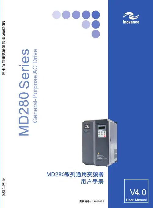
简介 MD280系列通用变频器用户手册简介MD280系列基本配置和功能如下:输入输出端子5×DI(DI5可以选择为高速输入口)2×AI(AI2 可选电压或电流输入,同时AI2 还可选择为键盘电位器给定)2×DO1×AO(可选电压/电流输出,也可通过FM选择为频率输出或DO输出)1×继电器输出控制方式V/F模拟给定方式直线模式多段速可实现8段速简易PLC可实现8段定时运行摆频及定长控制有通讯功能自带485 通讯口PID控制有V/F方式直线V/F,多点V/F,平方V/F开箱验货:在开箱时,请认真确认:1)本机铭牌的型号及变频器额定值是否与您的订货一致。
箱内含您订购的机器、产品合格证、用户操作手册及保修单。
2)产品在运输过程中是否有破损现象;若发现有某种遗漏或损坏,请速与本公司或您的供货商联系解决。
初次使用:对于初次使用本产品的用户,应先认真阅读本手册。
若对一些功能及性能方面有所疑惑,请咨询我公司的技术支持人员,以获得帮助,对正确使用本产品有利。
由于致力于产品的不断改善,因此本公司所提供的资料如有变更,恕不另行通知。
MD280系列变频器符合下列国际标准:●IEC/EN 61800-5-1:2003可调速电气传动系统安规要求;●IEC/EN 61800-3:2004可调速电气传动系统;第三部分:产品的电磁兼容性标准及其特定的试验方法(按照7.3.2及7.3.6在正确安装和正确使用的条件下,满足IEC/EN61800-3标准要求)。
简介 MD280系列通用变频器用户手册Memo NO. _____Date / /______________________________________________________________________________________________________________________________________________________________________________________________________________________________________________________________________________________________________________________________________________________________________________________________________________________________________________________________________________________________________________________________________________________________________________________________________________________________________________________________________________________________________________________________________________________________________________________________________________________________________________________________________________________________________________________________________目录前言 (1)简介 (2)第一章安全信息及注意事项 (12)1.1 安全事项 (12)1.2 注意事项 (13)第二章产品信息 (18)2.1 命名规则 (18)2.2 MD280系列变频器各部分名称 (19)2.3 MD280变频器系列规格 (21)2.4 技术规范 (22)2.5 产品外型图、安装孔位尺寸 (24)2.6 选配件 (30)2.7 变频器的日常保养与维护 (31)2.7.1 日常保养 (31)2.7.2 定期检查 (31)2.7.3 变频器易损件更换 (32)2.7.4 变频器的存贮 (32)2.8 变频器的保修说明 (32)2.9 制动组件选型指南 (33)2.9.1 阻值的选择 (33)2.8.2 制动电阻的功率选择 (33)第三章机械与电气安装 (36)3.1 机械安装 (36)3.1.1 安装环境要求 (36)3.1.2 安装空间要求 (36)3.1.3 机械安装方法及步骤 (37)3.1.4 机械安装注意事项 (39)3.1.5 MD280系列变频器下盖板的拆卸和安装 (39)3.2 电气安装 (40)3.2.1 外围电气元件选型指导 (40)3.2.2 外围电气元件的使用说明 (41)3.2.3主电路端子说明 (42)3.2.4 接线方式 (43)3.2.5 各功率段变频器端子接线分布图 (45)3.2.6 主电路端子及接线 (47)3.2.7 控制端子及接线 (49)3.2.8 变频器DI端口的使用方法 (53)3.2.9 变频器DO端口的使用方法 (53)3.2.10 变频器AI端口的使用方法 (54)3.2.11 变频器AO端口的使用方法 (54)3.2.12 变频器串行通讯的使用方法 (55)第四章操作与显示 (58)4.1 操作与显示界面介绍 (58)4.2 功能码查看、修改方法说明 (60)4.3 状态参数的查阅 (60)4.4 简易使用流程说明 (62)4.4.1 简易试运行流程图 (62)4.4.2 简易运行流程图 (63)第五章参数说明 (66)5.1 电机参数设定 (66)5.2 VF曲线、负载类型设定 (67)5.3 启停命令源设定 (69)5.4 频率设定 (73)5.4.1通过操作面板进行频率设定 (73)5.4.2通过模拟量进行频率设定 (74)5.4.3通过高频脉冲进行频率设定 (76)5.4.4通过端子进行多段速频率设定、简易PLC 功能 (77)5.4.5通过PID给定频率 (81)5.4.6通过AI1 + AI2给定频率 (84)5.4.7通过PID +AI给定频率 (84)5.4.8通过通讯给定频率 (84)5.4.9主频率源、辅助频率源配合设定 (85)5.4.10命令源绑定主频率源设定 (88)5.5最大频率、上下限频率设定 (89)5.5.1最大频率、上下限频率设定 (89)5.5.2低于下限频率动作设定 (90)5.6 加减速时间与加减速曲线设定 (91)5.6.1加减速时间设定 (91)5.6.2加减速曲线设定 (92)5.7 电机启动、停机方式与直流制动设定 (94)5.7.1电机启动方式与启动直流制动设定 (94)5.7.2电机停机方式与停机直流制动设定 (96)5.8 点动运行设定 (97)5.9 电机与变频器保护设定 (98)5.9.1电机过载保护设定 (98)5.9.2电机过电流保护设定 (100)5.9.3变频器保护设定 (100)5.10外部输入和输出端子(DI、AI、DO、AO)功能选择 (101)5.10.1数字输入(DI)端子功能定义与选择 (101)5.10.2模拟量(AI)、高频脉冲(FM)输入端子功能定义与选择 (104)5.10.3数字输出(DO)端子功能定义与选择 (107)5.10.4模拟量(AO)、高频脉冲(FM)输出端子功能定义与选择 (109)5.11变频器故障时动作选择 (111)5.12电机噪音与电磁干扰的降低、电流振荡的抑制 (112)5.12.1电机噪音与电磁干扰的降低 (112)5.12.2电机电流振荡的抑制 (113)5.13 面板监视显示参数 (114)5.14 电机转矩提升 (116)5.15 变频器输出电流(转矩)限制 (117)5.16 变频器母线电压限制(以及制动电阻开通电压设定) (118)5.17 瞬时停电连续运行(瞬停不停) (120)5.18 转速跟踪再启动 (122)5.19 转差补偿 (123)5.20 电机参数静态调谐 (124)5.21 辅助功能 (125)5.21.1跳频 (125)5.21.2正反转死区时间及禁止反转 (126)5.21.3设定运行时间及动作 (127)5.21.4上电时间 (128)5.21.5风扇控制、启动命令保护 (128)5.21.6外部抱闸控制 (128)5.21.7频率检测到达及动作 (129)5.21.8操作面板按键功能设定 (131)5.21.9计用电量、发电量功能 (132)5.22休眠与唤醒、负载速度显示 (133)5.22.1 休眠与唤醒 (133)5.22.2 负载速度显示 (134)5.23 摆频、定长和计数 (135)5.23.1摆频 (135)5.23.2定长与计数 (137)5.24 变频器故障记录 (140)5.25 零漂检测、AI校正、欠压点设定 (141)5.26 第二电机参数 (142)5.27 变频器参数恢复出厂、用户密码 (143)第六章 EMC(电磁兼容性) (146)6.1 相关术语定义 (146)6.2 EMC标准介绍 (146)6.2.1 EMC标准 (146)6.2.2 安装环境EMC要求 (146)6.3 EMC外围配件安装选型指导 (147)6.3.1 电源输入端加装EMC输入滤波器 (147)6.3.2电源输入端加装交流输入电抗器 (148)6.3.3 变频器输出侧加装交流输出电抗器 (149)6.4 屏蔽电缆 (150)6.4.1 屏蔽电缆要求 (150)6.4.2 电缆布线要求 (152)6.5 漏电流应对要求 (153)6.6 常见EMC干扰问题整改建议 (153)第七章故障诊断及对策 (156)7.1 故障报警及对策 (156)7.2 常见故障及其处理方法 (158)附录A 通讯协议 (160)A.1 协议内容 (160)A.2 应用方式 (160)A.3 总线结构 (160)A.4 协议说明 (160)A.5 通讯数据结构 (160)A.6 FA组通讯参数说明 (168)附录B 典型用例 (169)B.1 陶瓷窑炉风机控制系统 (169)B.2 钢化玻璃风机控制系统 (171)B.3 恒压供水控制系统 (173)B.4 冲床控制系统 (175)附录C 功能参数表 (177)附录D 版本变更记录 (192)Memo NO. _____Date / /______________________________________________________________________________________________________________________________________________________________________________________________________________________________________________________________________________________________________________________________________________________________________________________________________________________________________________________________________________________________________________________________________________________________________________________________________________________________________________________________________________________________________________________________________________________________________________________________________________________________________________________________________________________________________________________________________3PH AC380V 5.8A 50/60Hz。
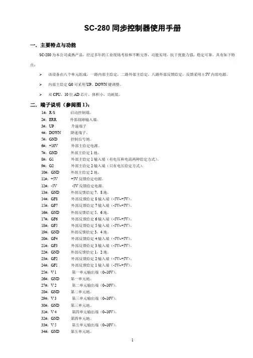
SC-280同步控制器使用手册一.主要特点与功能SC-280为本公司成熟产品,经过多年的工业现场考验和不断完善,功能实用,抗干扰能力强,稳定可靠。
具有如下特点:该设备由八个单元组成,一路内部主给定,二路外部主给定,八路外部反馈给定,反馈采用±5V内部电源。
内部主给定G0可采用UP、DOWN键调整。
双CPU,10位AD芯片,体积小,功耗低。
二.端子说明(参阅图1):1#:R/S 启动控制端。
2#:ERR 外部故障输入端。
3#:UP 升速端子4#:DOWN 降速端子。
5#:GND 控制信号地。
6#:+10V 外部主给定电源。
7#:GND 外部主给定1地。
8#:G1 外部主给定1输入端(有电压和电流两种给定方式)。
9#:G2 外部主给定2输入端(只有电压给定方式)。
10#:GND 外部主给定2地。
11#:+5V +5V反馈给定电源。
12#:-5V -5V反馈给定电源。
13#:GND 外部反馈给定7,8地。
14#:GF8 外部反馈给定8输入端(-5V~+5V)。
15#:GF7 外部反馈给定7输入端(-5V~+5V)。
16#:GND 外部反馈给定5,6地。
17#:GF6 外部反馈给定6输入端(-5V~+5V)。
18#:GF5 外部反馈给定5输入端(-5V~+5V)。
19#:GND 外部反馈给定3,4地。
20#:GF4 外部反馈给定4输入端(-5V~+5V)。
21#:GF3 外部反馈给定3输入端(-5V~+5V)。
22#:GND 外部反馈给定1,2地。
23#:GF2 外部反馈给定2输入端(-5V~+5V)。
24#:GF1 外部反馈给定1输入端(-5V~+5V)。
25#:V 1 第一单元输出端(0~10V)。
26#:GND 第一单元地。
27#:V 2 第二单元输出端(0~10V)。
28#:GND 第二单元地。
29#:V 3 第三单元输出端(0~10V)。
30#:GND 第三单元地。
31#:V 4 第四单元输出端(0~10V)。
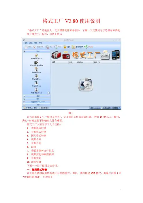
格式工厂V2.80使用说明“格式工厂”功能强大,是多媒体制作必备软件,了解一下其使用方法是很有必要的。
打开格式工厂程序,如图1所示图1首先点击图1中“输出文件夹”,定义输出文件的存放位置,例如D: \格式工厂输出,以免一时疏忽找不到输出文件在哪里。
格式工厂大致有以下几个功能:1.视频格式转换2.音频格式转换3.图片格式转换4.视频合并5.音频合并6.混流7.查看多媒体文件信息8.视频剪切和画面裁剪9.音频剪切10.附加字幕下面一一进行使用方法介绍。
一﹑视频格式转换首先要设置将视频转换成什么样的格式。
例如,要转换成A VI格式,那就点击图1中“所有转到AVI”,出现图2再点击图2中“输出配置”,出现图3图3由图3可见,视频流中,只规定了视频编码格式为MPEG4(Xvid),其它参数缺省或自动,这就意味着输出视频具有与源视频同样的分辨率(屏幕大小)和帧率(每秒帧数);音频流是完全确定了。
如果你认定可以这样设置,那就点击“确定”,继续往下进行。
如果你还要详细设置,就再点击图3中“高质量和大小”,出现一个选项下拉菜单,你选择一项,例如选取“HD 720x480 A VC”,将出现图4。
图4由图4可见,不管源视频的各参数如何,转换后所得的视频格式各参数如图4所示:视频编码格式为A VC(H264);分辨率为720x480;码率为1000;帧率为25,等等。
点击图4中“确定”,出现图5。
图5点击图5中“添加文件”,把要进行格式转换的视频打开,如图6。
图6至此,视频输出格式和要进行转换的视频文件都确定了。
再点击图6中“确定”,出现图7图7最后点击图7中“开始”,便开始进行视频格式转换。
转换完成后,点击图7中“清空列表”,便把源视频文件从列表中去掉。
也可先点击源视频文件,再点击“移除”,效果相同。
二﹑音频格式转换点击图1中左边的“音频”,将出现图8图8首先要设置将音频转换成什么样的格式。
例如,要转换成WMA格式,那就点击图8中“所有转到WMA”,出现图9图9再点击图9中“输出配置”,出现图10图10如果你认定可以这样设置,那就点击“确定”,继续往下进行。
IP camera tester 网络视频监控测试仪使用手册(IPC1.03)⏹感谢您购买工程宝安防监控视频测试仪。
使用前请务必阅读使用说明书,并正确使用。
⏹为了能安全地使用本仪器,请您先仔细阅读使用说明书上的「安全注意事项」。
⏹说明书阅读后请妥善保管,以便随时查阅、参考。
⏹附有的保修凭证或机身的保修封贴,请勿损坏。
⏹使用中遇到问题,或仪器出现损坏时,请与公司技术部联系。
目录一、安全事项--------------------------------------------------------- 1二、IP网络视频监控测试仪简介 ------------------------------------------- 22.1 概述------------------------------------------------------- 22.2 产品特点---------------------------------------------------- 22.3 产品功能---------------------------------------------------- 42.4 产品配件--------------------------------------------------- 102.5 仪表各部位名称和功能: --------------------------------------- 11三、操作说明-------------------------------------------------------- 143.1 电池安装及充电说明------------------------------------------- 143.2 仪器连接--------------------------------------------------- 153.2.1 网络摄像机连接---------------------------------------- 153.2.2模拟摄像机连接 ---------------------------------------- 163.3 功能菜单操作------------------------------------------------ 173.3.1 视频监控--------------------------------------------- 19(1) 云台控制器参数设置---------------------------------- 20(2) 色彩及存储设置------------------------------------- 22(3)视频图像放大---------------------------------------- 23(4)拍照截图------------------------------------------- 24(5)录像功能------------------------------------------- 24(6)相片浏览------------------------------------------- 25(7)录像回放------------------------------------------- 26(8)视频信号测量---------------------------------------- 273.3.2 图像发生器 TV OUT ------------------------------------ 293.3.3 ONVIF网络摄像机测试----------------------------------- 303.3.4IP网络摄像机测试--------------------------------------- 373.3.5 IP地址扫描 ------------------------------------------ 393.3.6 PING连通性测试--------------------------------------- 403.3.7 网线测试器------------------------------------------- 413.3.8 寻线器*(*定制功能型号见附表)-------------------------- 423.3.9 端口闪烁--------------------------------------------- 433.3.10 串口工具-------------------------------------------- 443.3.11 激光功率计*(*定制功能型号见附表)---------------------- 453.3.12 可见红光源*(*定制功能型号见附表)---------------------- 473.3.13 高精度数字万用表*(*定制功能型号见附表)----------------- 483.3.14 视频播放器------------------------------------------ 543.3.15 音乐播放器------------------------------------------ 553.3.16 手电筒--------------------------------------------- 563.3.17 PoE测试功能 ---------------------------------------- 573.3.18 计算器--------------------------------------------- 573.3.19 浏览器--------------------------------------------- 613.3.20 IPC viewer --------------------------------------- 623.3.21 DC12V电源输出-------------------------------------- 633.3.22 应用工具-------------------------------------------- 653.3.23 APPS工具夹----------------------------------------- 713.3.24 系统设置-------------------------------------------- 723.3.25 更新----------------------------------------------- 743.4音频测试功能 ------------------------------------------------ 75四、技术参数-------------------------------------------------------- 784.1 技术参数总表------------------------------------------------ 784.2 万用表技术参数---------------------------------------------- 794.3 光功率计技术参数 -------------------------------------------- 824.4可见红光源技术参数-------------------------------------------- 82一、安全事项⏹使用本仪器时,请遵守当地的电气使用相关规则,避免于医院、加油站等不可使用电气的地方使用。
上海自仪九仪表有限公司A/SS 版本:2008.04 GLJ - B026 – C - Z目 录一 概述 1二 选型编码 2三 技术性能 3四 工作原理和结构 3五 外形尺寸与安装尺寸 5六 安装 6七 使用 9八 维护 12九 储存和回公司的运输 15十 订货须知 15 十一 装箱 16一 概 述本说明书用于上海自动化仪表九厂设计、生产的LB型刮板流量计的安装、使用与维护。
本厂地址:上海市嘉定区安亭镇昌吉路157号邮政编码:201805 电话:(021) 59577979 (总机)上海自动化仪表九厂保留对本说明书解释与更改的权利,如有更改,恕不另行通知。
LB型刮板流量计(以下简称刮板流量计或流量计)是一种容积式流量测量仪表,用于测量充满于封闭管道中连续流过的液体的体积流量。
流量计具有现场指示的机械式计数器,不必外加能源即可获得直读的累积体积总量,清晰明了,操作简便,测量精度高,工作可靠,牢固耐用。
除此之外,每台流量计均有标准的转数输出轴,安装光电式电脉冲转换器后输出电脉冲信号,配上相应的流量数字积算仪,可以进行远距离读数,累积和数据监控。
主要适用于原油和石油制品的精确计量。
适于使用刮板流量计进行流量计量的流体应:●对流量计接触流体的部件(主要为铸钢、铸铁材料)无腐蚀,●具有较高的粘度的(3mPa·s~500mPa·s),●清洁的,不含固体杂质的液体,●其他的流体参数,请参阅本说明书第二章《技术性能》。
主要适用于原油和石油制品的精确计量。
本产品执行标准:Q/TDSM03-2005。
如果用户有不同于本说明书所介绍的流量计的安装、使用、要求,或有可能的改进建议,请与本厂联系。
为保证产品质量,相关部件已做前期磨合。
出厂时,大字轮总累积显示第1位数字不小于“1”。
总累积显示:不可回零的字轮部分二、选型编码项目及内容代码举例刮板流量计LB LB-公称通径(mm)50 80 100 150 200 250 300 508010015020025030050特征代号普通型不锈钢型AFA材料(由特征代号确定)特殊要求09公称压力PN1.6 PN2.5 PN4.0 PN6.3 PN2.0 PN5.0 ABCDEFB精确度等级0.2级0.5级232输出无脉冲输出(另配LPJ-12D)4~20mA电流输出(另配LPJ-12D/FI)ABCA显示大字轮 33选型举例:LB-50A0B2A3表示:刮板流量计,公称通径:50mm,特征代号:普通型,公称压力:PN2.5MPa, 精度等级:0.2级,输出:无输出,显示:大字轮显示。
TMS320F2809, TMS320F2808, TMS320F2806, TMS320F2802, TMS320F2801TMS320C2802, TMS320C2801,and TMS320F2801x DSPs数据手册著作编号:SPRS230J2003年-2007年9月修正除非有其他说明,本文档中包含了自发布日起的产品数据信息。
同时,产品也与德州仪器的每期标准规范说明书一致。
对产品的处理不包括所有参数的测试。
目录修订历史1 F280x,C2801x,C280x DSPs1.1特点1.2商标2 介绍2.1 引脚分配2.2 信号描述3 功能概况3.1 内存映射3.2 简单描述3.2.1 C28X CPU3.2.2 存储器总线(哈佛总线结构)3.2.3 外设总线3.2.4 实时JTAG接口和分析3.2.5 FLASH存储器3.2.6 ROM存储器3.2.7 M0,M1 SARAMs3.2.8 L0,L1,H0 SARAMs3.2.9 BOOT ROM3.2.10 安全性3.2.11 外设中断扩展(PIE)模块3.2.12 外部中断(XINT1,XINT2,XNMI)3.2.13 振荡器和锁相环(PLL)电路3.2.14 看门狗3.2.15 外部时钟3.2.16 低功耗模式3.2.17 外设框架3.2.18 通用输入输出(GPIO)复用引脚3.2.19 32位CPU定时器(0,1,2)3.2.20 控制外设3.2.21 串口外设3.3 寄存器映射3.4 器件仿真寄存器3.5 中断3.5.1 外部中断3.6 系统控制3.6.1 OSC和PLL模块3.6.2 看门狗模块3.7 低功耗模式模块4 外设4.1 32位CPU定时器0/1/24.2 增强型PWM模块(ePWM1/2/3/4/5/6)4.3 高精度PWM(HRPWM)4.4 增强型CAP模块(eCAP1/2/3/4)4.6 增强型AD转换模块4.6.1 ADC不用时引脚连接4.6.2 ADC寄存器4.7 增强型CAN模块(e-CAN-A和eCAN-B)4.8 SCI模组(SCI-A,SCI-B)4.9 SPI模组(SPI-A,SPI-B,SPI-C,SPI-D)4.10 I2C总线4.11 GPIO复用引脚5 器件支持5.1 器件和开发工具名称5.2 文档支持6 电路规范6.1 绝对最大额定值6.2 推荐运行条件6.3 电气特性6.4 电流消耗6.4.1 减小电流消耗6.4.2 电流消耗图表6.5 DSP无信号缓冲区时的引脚冲突连接6.6 时序参数模型6.6.1 时序参数的一般注意事项6.6.2 测试负荷电路6.7 时钟要求和特性6.8 上电时序6.8.1 电源管理和监控电路解决方案6.9 通用输入输出(GPIO)多路复用器6.9.1 GPIO-输出时序6.9.2 GPIO-输入时序6.10 增强型控制外设6.10.1 增强型脉宽调制(ePWM)时序6.10.2 Trip-Zone 输入时序6.10.3 外部中断时序6.10.4 I2C电路特性和时序6.10.5 串行外设接口(SPI)主动模式时序6.10.6串行外设接口(SPI)被动模式时序6.10.7 片上模-数转换器6.10.7.1 ADC上电控制位时序6.11 详细描述6.12 FLASH时序6.13 ROM时序(仅适用于C280x)7 从F280X到C280X的移植7.1 移植方法8 机械数据图形列表2-1 TMS320F2809,TMS320F2808 100-pin PZ LQFP(Top V iew)2-2 TMS320F2806 100-pin PZ LQFP(Top V iew)2-3 TMS320F2802,TMS320F2801,TMS320C2802,TMS320C2801,100-pin PZ LQFP(Top V iew)2-4 TMS320F2801x 100-Pin PZ LQFP(Top V iew)2-5 TMS320F2809,TMS320F2808,TMS320F2806,TMS320F2802,TMS320F2801,TMS320F28016,TMS320F28015,TMS320C2802,TMS320C2801 100-ball GGM and ZGM MicroStar BGA(Bottom View) 3-1 原理框图3-2 F2809内存映射3-3 F2808内存映射3-4 F2806内存映射3-5 F2802,C2802内存映射3-6 F2801, F28015,F28016,C2801内存映射3-7 外设中断资源3-8 使用外设中断模块时的中断复用3-9 时钟和复位电路3-10 OSC和PLL 方块图3-11 3.3V外部晶振的使用3-12 1.8V外部晶振的使用3-13 内部晶振的使用3-14 看门狗模块4-1 CPU定时器4-2 CPU定时器中断信号和输出信号4-3 280x系统的多路PWM模块4-4 ePWM4-5 eCAP功能方块图4-6 eQEP功能方块图4-7 ADC模块方块图4-8 使用内部参考时的ADC引脚连接4-9使用外部参考时的ADC引脚连接4-10 eCAN方块图和接口电路4-11 Ecan-A存储映射4-12 Ecan-B存储映射4-13 串行通信接口模组方块图4-14 SPI模组方块图(被动模式)4-15 I2C接口设计4-16 GPIO复用引脚方块图4-17 使用取样窗口的条件5-1 TMS320X280X器件命名举例6-1 典型的运行电流相对频率(F2808)6-2 典型的运行电流相对频率(F2808)6-3 无信号缓冲时的硬件连接6-4 3.3V测试负荷电路6-5 时钟时序6-7 热复位6-8 有效写入PLLCR寄存器的举例6-9 通用输出时序6-10 采样模式6-11 通用输入时序6-12 空闲进入和退出时序6-13 备用进入和退出时序6-14 使用通用IO口的中断唤醒6-15 PWM HI-Z特性6-16 ADCSOCAO or ADCSOCBO 时序6-17 外部中断时序6-18 SPI主动模式外部时序(CLOCK PHASE = 0)6-19 SPI主动模式外部时序(CLOCK PHASE = 1)6-20 SPI被动模式外部时序(CLOCK PHASE = 0)6-21 SPI被动模式外部时序(CLOCK PHASE = 1)6-22 ADC上电控制位时序6-23 ADC 模拟输入阻抗模式6-24 单通道模式时序6-25多通道模式时序表单列表2-1 硬件特性(100MHZ器件)2-2 硬件特性(60MHZ器件)2-3 信号描述3-1 F2809的FLASH段地址3-2 F2808的FLASH段地址3-3 F2802、F2806的FLASH段地址3-4 F2801、F28015、F28016的FLASH段地址3-5 使用代码保护模式的影响3-6 等待状态3-7 自举模式选择3-8 外部frame0寄存器3-9 外部frame1寄存器3-10 外部frame2寄存器3-11 器件硬件寄存器3-12 PIE外部中断3-13 PIE配置和控制寄存器3-14 外部中断寄存器3-15 PLL,Clocking,Watchdog,and Low-Power Mode 寄存器3-16 PLLCR寄存器位定义3-17 可能的PLL配置模式3-18 低功耗模式4-1 CPU定时器0,1,2配置和控制寄存器4-2 ePWM控制和标准寄存器4-4 eQEP控制和标准寄存器4-5 ADC寄存器4-6 3.3V eCAN收发器4-7 CAN寄存器MAP4-8 SCI-A寄存器4-9 SCI-B寄存器4-10 SPI-A寄存器4-11 SPI-B寄存器4-12 SPI-C寄存器4-13 SPI-D寄存器4-14 SPI-C寄存器4-15 GPIO寄存器4-16 F2808 GPIO复用表6-1 系统时钟为100MHZ时TMS320F2809,TMS320F2808的电流消耗6-2系统时钟为100MHZ时TMS320F2806的电流消耗6-3系统时钟为100MHZ时TMS320F2802,TMS320F2801的电流消耗6-4系统时钟为100MHZ时TMS320C2802,TMS320C2801的电流消耗6-5各种外设的典型电流消耗(100MHZ时)6-6 TMS320x280x时钟表和命名(100MHZ器件)6-7 TMS320x280x时钟表和命名(60MHZ器件)6-8 输入时钟频率6-9 XCLKIN时序要求-PLL enabled6-10 XCLKIN时序要求-PLL disabled6-11 XCLKOUT 开关特性(PLL bypassed or enabled)6-12 电源管理和监控电路解决方案6-13 Reset(XRS)时序要求6-14 通用输出开关特性6-15 通用输入时序要求6-16 IDLE模式时序要求6-17 IDLE模式开关特性6-18 STANDBY模式时序要求6-19 STANDBY模式开关特性6-20 HALT模式时序要求6-21 HALT模式开关特性6-22 ePWM时序要求6-23 ePWM开关特性6-24 Trip-Zone 输入时序要求6-25 高精度PWM特性(SYSCLKOUT=(60~100MHZ)6-26 eCAP时序要求6-27 eCAP开关特性6-28 eQEP时序要求6-29 eQEP开关特性6-30 外部ADC启动转换开关特性6-31 外部中断时序要求6-32 外部重点开关特性6-34 SPI主动模式外部时序(Clock Phase=0)6-35 SPI主动模式外部时序(Clock Phase=1)6-36 SPI被动模式外部时序(Clock Phase=0)6-37 SPI被动模式外部时序(Clock Phase=0)6-38 ADC电器特性(通过推荐运行条件验证)6-39 ADC上电延时6-40 不同ADC配置时的电流消耗(ADCCLK=12.5MHZ)6-41 单通道模式时序6-42 多通道模式时序6-43 Flash耐性6-44 SYSCLKOUT=100MHZ时的Flash参数6-45 Flash/OTP进入时序6-46 不同频率时的最大最小要求Flash/OTP等待状态6-47 ROM/OTP进入时序6-48不同频率时的最大最小要求ROM/OTP等待状态8-1 F280x Thermal Model 100-pin GGM Results8-2 F280x Thermal Model 100-pin PZ Results8-3 C280x Thermal Model 100-pin GGM Results8-4 C280x Thermal Model 100-pin PZ Results8-5 F2809 Thermal Model 100-pin GGM Results8-6 F2809 Thermal Model 100-pin PZ Results版本历史注意:早期版本的页码可能和当前版本页码有所不同该数据手册自SPRS230I到SPRS230J修正该文档因保证技术的准确性,已经被再次审阅。
视频转换工具Media Player Utilities5.24_02操作指南
首先解压Media Player Utilities5.24_02工具包,打开解压后的文件
打开tool可以看到
点击安装,
点击下一步,一直点击下一步等到
提示安装完成
有些
电脑会提示安装驱动
,完成了之后,打开路径在电脑左下角的位置点击:
开始-----所有程序
——媒体播放器管理工具 4.45选择AMV&AVI视频转换工具点击运行
如图;
找到需要转换的视频目录,在输入文件夹里边找
图:
,选择需要转换的视频文件,然后在设置里边调分辨率,先在选择的文件哪里把
钩去掉再打一下,打了之后,打完之后可以看到设置图标变色
在设置里边调分辨率160*128
点击确定,选着箭头开始转换开始转换
装换完成的文件在输出文件夹里边找路径。