port-channel测试报告
- 格式:docx
- 大小:17.30 KB
- 文档页数:3
实验二交换实验_VLAN及链路冗余一、实验名称本次实验的实验名称为:交换实验,主要分为以下几个小实验:(1)同一交换机VLAN的划分,也称为交换机端口的隔离;(2)不同交换机上VLAN的划分(3)三层交换机使不同VLAN互通(4)端口聚合提供冗余链路二、实验目的1.同一交换机VLAN的划分在实现同一交换机VLAN的划分实验中,我们主要的目的是理解Port Vlan 的配置,动手实现在同一个交换机上划分VLAN。
2.不同交换机上VLAN的划分在实现不同交换机上VLAN的划分实验中,我们主要的目的是理解跨交换机之间VLAN的特点,可以动手实现在不同的交换机上划分VLAN。
3.三层交换机使不同VLAN互通在利用三层交换机实现不同VLAN互通的实验中,我们主要的目标是使用三层交换机实现不同VLAN间互相通信。
4.端口聚合提供冗余链路在实现交换机的端口聚合以提供冗余链路的实验过程中,我们的主要目标是理解链路聚合的配置及原理,动手实现交换机端口的聚合。
三、实验设备在本次实验的过程中,主要要求的实验设备有交换机2台:三层S3550-1,二层S2126G-1;PC机4台:PC1,PC2,PC5和PC6以及若干条直连线和交叉线。
四、实验拓扑图1.同一交换机VLAN的划分该实验主要使用了二层交换机S2126G-1和两台PC机PC5、PC6,IP地址设置、连接端口号的设置如下图(1)所示:图(1)2.不同交换机上VLAN的划分该实验主要使用了二层交换机S2126G-1、三层交换机S3550-1以及四台PC机PC1、PC2、PC5、PC6,IP地址设置、连接端口号的设置如下图(2)所示:图(2)3.三层交换机使不同VLAN互通该实验主要使用了二层交换机S2126G-1、三层交换机S3550-1以及四台PC机PC1、PC2、PC5、PC6,IP地址设置、连接端口号的设置如下图(3)所示:图(3)4.端口聚合提供冗余链路该实验主要使用了二层交换机S2126G-1、三层交换机S3550-1以及四台PC机PC1、PC2、PC5、PC6,IP地址设置、连接端口号的设置如下图(4)所示:图(4)五、实验内容(步骤)1.同一交换机VLAN的划分(1)按照实验拓扑图进行网络的连接和配置。
Changzhou V&M ProjectCisco Equipments验收报告项目名称:中国常州V&M网络工程---常州测试地点:常州用户代表(签字):____________________________________ Siemens 代表(签字):___________________________________ 测试日期:____________________________________________说明:本测试报告测试对象为CISCO C4506,C2950和C2955,为了确认设备的可用性,通过指示灯和命令检查设备状态以及功能的实现。
本报告一式两份,双方各执一份。
用户代表签字:SCNB代表签字:用户代表签字:SCNB代表签字:用户代表签字:SCNB代表签字:用户代表签字:SCNB代表签字:用户代表签字:SCNB代表签字:附件:1.VMC-2MDFB-C45-02#show versionCisco Internetwork Operating System SoftwareIOS (tm) Catalyst 4000 L3 Switch Software (cat4000-I9K91S-M), Version 12.2(20)EW3, RELEASE SOFTWARE (fc1)Technical Support: /techsupportCopyright (c) 1986-2005 by cisco Systems, Inc.Compiled Wed 07-Sep-05 11:30 by pwadeImage text-base: 0x00000000, data-base: 0x012B374CROM: 12.2(20r)EW1Dagobah Revision 226, Swamp Revision 31VMC-2MDFB-C45-02 uptime is 2 days, 4 hours, 22 minutesSystem returned to ROM by reloadSystem image file is "bootflash:"This product contains cryptographic features and is subject to UnitedStates and local country laws governing import, export, transfer anduse. Delivery of Cisco cryptographic products does not implythird-party authority to import, export, distribute or use encryption.Importers, exporters, distributors and users are responsible forcompliance with U.S. and local country laws. By using this product youagree to comply with applicable laws and regulations. If you are unableto comply with U.S. and local laws, return this product immediately.A summary of U.S. laws governing Cisco cryptographic products may be found at: /wwl/export/crypto/tool/stqrg.htmlIf you require further assistance please contact us by sending email toexport@.cisco WS-C4506 (MPC8245) processor (revision 14) with 524288K bytes of memory. Processor board ID FOX101902XXMPC8245 CPU at 333Mhz, Supervisor IVLast reset from Reload12 Virtual Ethernet/IEEE 802.3 interface(s)56 Gigabit Ethernet/IEEE 802.3 interface(s)403K bytes of non-volatile configuration memory.Configuration register is 0x2101附件:2.VMC-2MDFB-C45-02#show environment alarmno alarm附件:3.VMC-2MDFB-C45-02#show environment temperatureChassis Temperature = 34 degrees CelsiusChassis Over Temperature Threshold = 75 degrees Celsius Chassis Critical Temperature Threshold = 95 degrees Celsius附件:4.VMC-2MDFB-C45-02#show environment statusPower Fan InlineSupply Model No Type Status Sensor Status------ ---------------- --------- ----------- ------- ------- PS1 PWR-C45-1000AC AC 1000W good good n.a.PS2 PWR-C45-1000AC AC 1000W bad/off bad/off n.a.Power supplies needed by system : 1Power supplies currently available : 1Chassis Type : WS-C4506Power consumed by backplane : 0 WattsSupervisor Led Color : OrangeFantray : GoodPower consumed by Fantray : 50 Watts附件:5.VMC-2MDFB-C45-02#show runnBuilding configuration...Current configuration : 7684 bytes!version 12.2no service padservice timestamps debug uptimeservice timestamps log uptimeno service password-encryptionservice compress-config!hostname VMC-2MDFB-C45-02!enable password abc123!!username vmcadmin secret 5 $1$RGoF$.j9gprw9tThywfyTZ9T.W/ ip subnet-zero!no file verify auto!spanning-tree mode pvstspanning-tree portfast defaultspanning-tree extend system-idspanning-tree vlan 1,12,51-53,71,91-93 priority 28672 spanning-tree vlan 11,54,94,101,201-204,301 priority 24576 power redundancy-mode redundant!!!vlan internal allocation policy ascending!interface Port-channel1switchportswitchport trunk encapsulation dot1qswitchport trunk native vlan 11switchport mode trunk!interface GigabitEthernet1/1switchport trunk encapsulation dot1qswitchport trunk native vlan 11switchport mode trunkchannel-group 1 mode desirable non-silent!interface GigabitEthernet1/2switchport trunk encapsulation dot1qswitchport trunk native vlan 11switchport mode trunkchannel-group 1 mode desirable non-silent!interface GigabitEthernet2/1switchport trunk encapsulation dot1qswitchport trunk native vlan 11switchport mode trunk!interface GigabitEthernet2/2switchport trunk encapsulation dot1q switchport trunk native vlan 11switchport mode trunk!interface GigabitEthernet2/3switchport trunk encapsulation dot1q switchport trunk native vlan 11switchport mode trunk!interface GigabitEthernet2/4switchport trunk encapsulation dot1q switchport trunk native vlan 11switchport mode trunk!interface GigabitEthernet2/5switchport trunk encapsulation dot1q switchport trunk native vlan 11switchport mode trunk!interface GigabitEthernet2/6switchport trunk encapsulation dot1q switchport trunk native vlan 11switchport mode trunk!interface GigabitEthernet3/1switchport access vlan 51switchport mode accessspeed 100duplex fullspanning-tree portfast!interface GigabitEthernet3/2switchport access vlan 511switchport mode accessspeed 100duplex fullspanning-tree portfast!interface GigabitEthernet3/3switchport access vlan 52switchport mode accessspeed 100duplex fullspanning-tree portfast!interface GigabitEthernet3/4 switchport access vlan 52switchport mode accessspeed 100duplex fullspanning-tree portfast!interface GigabitEthernet3/5 switchport access vlan 52switchport mode accessspeed 100duplex fullspanning-tree portfast!interface GigabitEthernet3/6 switchport access vlan 52switchport mode accessspeed 100duplex fullspanning-tree portfast!interface GigabitEthernet3/7 switchport access vlan 53switchport mode accessspeed 100duplex fullspanning-tree portfast!interface GigabitEthernet3/8 switchport access vlan 53switchport mode accessspeed 100duplex fullspanning-tree portfast!interface GigabitEthernet3/9 switchport access vlan 54switchport mode accessspeed 100duplex fullspanning-tree portfast!interface GigabitEthernet3/10 switchport access vlan 54switchport mode accessspeed 100duplex fullspanning-tree portfast!interface GigabitEthernet3/11 switchport access vlan 54switchport mode accessspeed 100duplex fullspanning-tree portfast!interface GigabitEthernet3/12 switchport access vlan 54switchport mode accessspeed 100duplex fullspanning-tree portfast!interface GigabitEthernet3/13 switchport access vlan 91switchport mode accessspeed 100duplex fullspanning-tree portfast!interface GigabitEthernet3/14 switchport access vlan 91switchport mode accessspeed 100duplex fullspanning-tree portfast!interface GigabitEthernet3/15 switchport access vlan 91switchport mode accessspeed 100duplex fullspanning-tree portfast!interface GigabitEthernet3/16 switchport access vlan 91switchport mode accessspeed 100duplex fullspanning-tree portfast!interface GigabitEthernet3/17 switchport access vlan 92spanning-tree portfast!interface GigabitEthernet3/18 switchport access vlan 92spanning-tree portfast!interface GigabitEthernet3/19 switchport access vlan 92spanning-tree portfast!interface GigabitEthernet3/20 switchport access vlan 92spanning-tree portfast!interface GigabitEthernet3/21 switchport access vlan 92spanning-tree portfast!interface GigabitEthernet3/22 switchport access vlan 92spanning-tree portfast!interface GigabitEthernet3/23 switchport access vlan 92spanning-tree portfast!interface GigabitEthernet3/24 switchport access vlan 92spanning-tree portfast!interface GigabitEthernet3/25 switchport access vlan 92spanning-tree portfast!switchport access vlan 92spanning-tree portfast!interface GigabitEthernet3/27 switchport access vlan 93switchport mode accessspanning-tree portfast!interface GigabitEthernet3/28 switchport access vlan 93switchport mode accessspanning-tree portfast!interface GigabitEthernet3/29 switchport access vlan 94switchport mode accessspanning-tree portfast!interface GigabitEthernet3/30 switchport access vlan 94switchport mode accessspanning-tree portfast!interface GigabitEthernet3/31 !interface GigabitEthernet3/32 !interface GigabitEthernet3/33 !interface GigabitEthernet3/34 !interface GigabitEthernet3/35 !interface GigabitEthernet3/36 !interface GigabitEthernet3/37 !interface GigabitEthernet3/38 !interface GigabitEthernet3/39 !interface GigabitEthernet3/40 !!interface GigabitEthernet3/42!interface GigabitEthernet3/43!interface GigabitEthernet3/44!interface GigabitEthernet3/45!interface GigabitEthernet3/46!interface GigabitEthernet3/47!interface GigabitEthernet3/48switchport access vlan 51switchport mode accessspeed 10duplex fullspanning-tree portfast!interface Vlan1no ip address!interface Vlan11ip address 10.65.138.66 255.255.255.224 !interface Vlan12ip address 10.65.138.131 255.255.255.224 standby 12 ip 10.65.138.129standby 12 priority 95standby 12 preempt!interface Vlan52ip address 10.65.129.70 255.255.255.224 standby 51 ip 10.65.129.68standby 51 priority 95standby 51 preempt!interface Vlan71ip address 10.65.129.131 255.255.255.224 standby 71 ip 10.65.129.129standby 71 priority 95standby 71 preemptinterface Vlan92ip address 10.65.132.130 255.255.255.192standby 92 ip 10.65.132.129standby 92 preempt!interface Vlan101ip address 10.65.128.3 255.255.255.0standby 101 ip 10.65.128.1standby 101 priority 95standby 101 preempt!interface Vlan201ip address 10.65.140.67 255.255.255.128standby 201 ip 10.65.140.65standby 201 priority 95standby 201 preempt!interface Vlan202ip address 10.65.140.131 255.255.255.128standby 202 ip 10.65.140.129standby 202 preempt!interface Vlan203ip address 10.65.131.3 255.255.255.0standby 203 ip 10.65.131.1standby 203 preempt!interface Vlan204ip address 10.65.130.3 255.255.255.0standby 204 ip 10.65.130.1standby 204 priority 95standby 204 preempt!interface Vlan301ip address 10.65.17.3 255.255.255.0standby 255 ip 10.65.17.1standby 255 preemptstandby 255 name forVlan301!ip route 0.0.0.0 0.0.0.0 10.65.129.65ip route 10.65.132.64 255.255.255.192 10.65.129.65 no ip http server!!access-list 1 permit 10.65.132.64 0.0.0.63access-list 2 permit 10.65.128.0 0.0.0.255!route-map OUT-of-DMZ permit 10match ip address 1set ip next-hop 10.65.129.65!route-map OUT-of-DMZ permit 20!route-map PBR-SAP permit 10match ip address 2set ip next-hop 10.65.129.97!route-map PBR-SAP permit 20!!!line con 0logging synchronousstopbits 1line vty 0 4login local!endVMC-2MDFB-C45-02#show startup-configUsing 2677 out of 413676 bytes, uncompressed size = 7568 bytes Uncompressed configuration from 2677 bytes to 7568 bytes!version 12.2no service padservice timestamps debug uptimeservice timestamps log uptimeno service password-encryptionservice compress-config!hostname VMC-2MDFB-C45-02!enable password abc123!!username vmcadmin secret 5 $1$RGoF$.j9gprw9tThywfyTZ9T.W/ip subnet-zerono file verify auto!spanning-tree mode pvstspanning-tree portfast defaultspanning-tree extend system-idspanning-tree vlan 1,12,51-53,71,91-93 priority 28672 spanning-tree vlan 11,54,94,101,201-204,301 priority 24576 power redundancy-mode redundant!!!vlan internal allocation policy ascending!interface Port-channel1switchportswitchport trunk encapsulation dot1qswitchport trunk native vlan 11switchport mode trunk!interface GigabitEthernet1/1switchport trunk encapsulation dot1qswitchport trunk native vlan 11switchport mode trunkchannel-group 1 mode desirable non-silent!interface GigabitEthernet1/2switchport trunk encapsulation dot1qswitchport trunk native vlan 11switchport mode trunkchannel-group 1 mode desirable non-silent!interface GigabitEthernet2/1switchport trunk encapsulation dot1qswitchport trunk native vlan 11switchport mode trunk!interface GigabitEthernet2/2switchport trunk encapsulation dot1qswitchport trunk native vlan 11switchport mode trunk!interface GigabitEthernet2/3switchport trunk encapsulation dot1qswitchport trunk native vlan 11switchport mode trunk!interface GigabitEthernet2/4switchport trunk encapsulation dot1q switchport trunk native vlan 11switchport mode trunk!interface GigabitEthernet2/5switchport trunk encapsulation dot1q switchport trunk native vlan 11switchport mode trunk!interface GigabitEthernet2/6switchport trunk encapsulation dot1q switchport trunk native vlan 11switchport mode trunk!interface GigabitEthernet3/1switchport access vlan 51switchport mode accessspeed 100duplex fullspanning-tree portfast!interface GigabitEthernet3/2switchport access vlan 511switchport mode accessspeed 100duplex fullspanning-tree portfast!interface GigabitEthernet3/3switchport access vlan 52switchport mode accessspeed 100duplex fullspanning-tree portfast!interface GigabitEthernet3/4switchport access vlan 52switchport mode accessspeed 100duplex fullspanning-tree portfast!interface GigabitEthernet3/5 switchport access vlan 52switchport mode accessspeed 100duplex fullspanning-tree portfast!interface GigabitEthernet3/6 switchport access vlan 52switchport mode accessspeed 100duplex fullspanning-tree portfast!interface GigabitEthernet3/7 switchport access vlan 53switchport mode accessspeed 100duplex fullspanning-tree portfast!interface GigabitEthernet3/8 switchport access vlan 53switchport mode accessspeed 100duplex fullspanning-tree portfast!interface GigabitEthernet3/9 switchport access vlan 54switchport mode accessspeed 100duplex fullspanning-tree portfast!interface GigabitEthernet3/10 switchport access vlan 54switchport mode accessspeed 100duplex fullspanning-tree portfast!interface GigabitEthernet3/11 switchport access vlan 54switchport mode accessspeed 100duplex fullspanning-tree portfast!interface GigabitEthernet3/12 switchport access vlan 54switchport mode accessspeed 100duplex fullspanning-tree portfast!interface GigabitEthernet3/13 switchport access vlan 91switchport mode accessspeed 100duplex fullspanning-tree portfast!interface GigabitEthernet3/14 switchport access vlan 91switchport mode accessspeed 100duplex fullspanning-tree portfast!interface GigabitEthernet3/15 switchport access vlan 91switchport mode accessspeed 100duplex fullspanning-tree portfast!interface GigabitEthernet3/16 switchport access vlan 91switchport mode accessspeed 100duplex fullspanning-tree portfast!interface GigabitEthernet3/17 switchport access vlan 92spanning-tree portfast!interface GigabitEthernet3/18 switchport access vlan 92spanning-tree portfast!interface GigabitEthernet3/19 switchport access vlan 92spanning-tree portfast!interface GigabitEthernet3/20 switchport access vlan 92spanning-tree portfast!interface GigabitEthernet3/21 switchport access vlan 92spanning-tree portfast!interface GigabitEthernet3/22 switchport access vlan 92spanning-tree portfast!interface GigabitEthernet3/23 switchport access vlan 92spanning-tree portfast!interface GigabitEthernet3/24 switchport access vlan 92spanning-tree portfast!interface GigabitEthernet3/25 switchport access vlan 92spanning-tree portfast!interface GigabitEthernet3/26 switchport access vlan 92spanning-tree portfast!interface GigabitEthernet3/27 switchport access vlan 93switchport mode accessspanning-tree portfast!interface GigabitEthernet3/28switchport access vlan 93switchport mode accessspanning-tree portfast!interface GigabitEthernet3/29 switchport access vlan 94switchport mode accessspanning-tree portfast!interface GigabitEthernet3/30 switchport access vlan 94switchport mode accessspanning-tree portfast!interface GigabitEthernet3/31 !interface GigabitEthernet3/32 !interface GigabitEthernet3/33 !interface GigabitEthernet3/34 !interface GigabitEthernet3/35 !interface GigabitEthernet3/36 !interface GigabitEthernet3/37 !interface GigabitEthernet3/38 !interface GigabitEthernet3/39 !interface GigabitEthernet3/40 !interface GigabitEthernet3/41 !interface GigabitEthernet3/42 !interface GigabitEthernet3/43 !interface GigabitEthernet3/44 !interface GigabitEthernet3/45 !interface GigabitEthernet3/46!interface GigabitEthernet3/47!interface GigabitEthernet3/48switchport access vlan 51switchport mode accessspeed 10duplex fullspanning-tree portfast!interface Vlan1no ip address!interface Vlan11ip address 10.65.138.66 255.255.255.224 !interface Vlan12ip address 10.65.138.131 255.255.255.224 standby 12 ip 10.65.138.129standby 12 priority 95standby 12 preempt!interface Vlan52ip address 10.65.129.70 255.255.255.224 standby 51 ip 10.65.129.68standby 51 priority 95standby 51 preempt!interface Vlan71ip address 10.65.129.131 255.255.255.224 standby 71 ip 10.65.129.129standby 71 priority 95standby 71 preempt!interface Vlan92ip address 10.65.132.130 255.255.255.192 standby 92 ip 10.65.132.129standby 92 preempt!interface Vlan101ip address 10.65.128.3 255.255.255.0standby 101 ip 10.65.128.1standby 101 priority 95standby 101 preempt!interface Vlan201ip address 10.65.140.67 255.255.255.128standby 201 ip 10.65.140.65standby 201 priority 95standby 201 preempt!interface Vlan202ip address 10.65.140.131 255.255.255.128standby 202 ip 10.65.140.129standby 202 preempt!interface Vlan203ip address 10.65.131.3 255.255.255.0standby 203 ip 10.65.131.1standby 203 preempt!interface Vlan204ip address 10.65.130.3 255.255.255.0standby 204 ip 10.65.130.1standby 204 priority 95standby 204 preempt!interface Vlan301ip address 10.65.17.3 255.255.255.0standby 255 ip 10.65.17.1standby 255 preemptstandby 255 name forVlan301!ip route 0.0.0.0 0.0.0.0 10.65.129.65ip route 10.65.132.64 255.255.255.192 10.65.129.65 no ip http server!!!access-list 1 permit 10.65.132.64 0.0.0.63access-list 2 permit 10.65.128.0 0.0.0.255!route-map OUT-of-DMZ permit 10match ip address 1set ip next-hop 10.65.129.65!route-map PBR- permit 10!!!line con 0logging synchronousstopbits 1line vty 0 4login local!end附件:6.VMC-2MDFB-C45-02#show vtp statusVTP Version : 2Configuration Revision : 29Maximum VLANs supported locally : 1005Number of existing VLANs : 23VTP Operating Mode : ServerVTP Domain Name : VMCVTP Pruning Mode : EnabledVTP V2 Mode : EnabledVTP Traps Generation : DisabledMD5 digest : 0x8E 0x66 0xE7 0x9E 0x3E 0x81 0x93 0x18 Configuration last modified by 10.65.138.66 at 7-13-06 00:37:34Local updater ID is 10.65.138.66 on interface Vl11 (lowest numbered VLAN interface found)附件:7.VMC-2MDFB-C45-02#show vlanVLAN Name Status Ports---- -------------------------------- --------- ------------------------------- 1 default active Gi2/1, Gi2/2, Gi2/3, Gi2/4Gi2/5, Gi2/6, Gi3/31, Gi3/32Gi3/33, Gi3/34, Gi3/35, Gi3/36Gi3/37, Gi3/38, Gi3/39, Gi3/40Gi3/41, Gi3/42, Gi3/43, Gi3/44Gi3/45, Gi3/46, Gi3/4711 NetworkManagement active12 NetworkPrinter active51 VLAN0051 active Gi3/1, Gi3/4852 VLAN0052 active Gi3/3, Gi3/4, Gi3/5, Gi3/653 VLAN0053 active Gi3/7, Gi3/854 VLAN0054 active Gi3/9, Gi3/10, Gi3/11, Gi3/1271 VoiceSys active91 VLAN0091 active Gi3/13, Gi3/14, Gi3/15, Gi3/1692 VLAN0092 active Gi3/17, Gi3/18, Gi3/19, Gi3/20Gi3/21, Gi3/22, Gi3/23, Gi3/24Gi3/25, Gi3/2693 SQL_SYN active Gi3/27, Gi3/2894 EXC_SYN active Gi3/29, Gi3/30101 SAPApplication activeVLAN Name Status Ports---- -------------------------------- --------- ------------------------------- 201 FinanaceDepart active202 HRDepart active203 DataUser active204 Data active301 Process active511 CP_SYN active Gi3/21002 fddi-default act/unsup1003 trcrf-default act/unsup1004 fddinet-default act/unsup1005 trbrf-default act/unsupVLAN Type SAID MTU Parent RingNo BridgeNo Stp BrdgMode Trans1 Trans2---- ----- ---------- ----- ------ ------ -------- ---- -------- ------ ------ 1 enet 100001 1500 - - - - - 0 011 enet 100011 1500 - - - - - 0 012 enet 100012 1500 - - - - - 0 051 enet 100051 1500 - - - - - 0 052 enet 100052 1500 - - - - - 0 053 enet 100053 1500 - - - - - 0 054 enet 100054 1500 - - - - - 0 071 enet 100071 1500 - - - - - 0 091 enet 100091 1500 - - - - - 0 092 enet 100092 1500 - - - - - 0 0VLAN Type SAID MTU Parent RingNo BridgeNo Stp BrdgMode Trans1 Trans2---- ----- ---------- ----- ------ ------ -------- ---- -------- ------ ------93 enet 100093 1500 - - - - - 0 094 enet 100094 1500 - - - - - 0 0101 enet 100101 1500 - - - - - 0 0201 enet 100201 1500 - - - - - 0 0202 enet 100202 1500 - - - - - 0 0203 enet 100203 1500 - - - - - 0 0204 enet 100204 1500 - - - - - 0 0301 enet 100301 1500 - - - - - 0 0511 enet 100511 1500 - - - - - 0 01002 fddi 101002 1500 - - - - - 0 01003 trcrf 101003 4472 1005 3276 - - srb 0 01004 fdnet 101004 1500 - - - ieee - 0 01005 trbrf 101005 4472 - - 15 ibm - 0 0VLAN AREHops STEHops Backup CRF---- ------- ------- ----------1003 0 0 offRemote SPAN VLANs------------------------------------------------------------------------------Primary Secondary Type Ports------- --------- ----------------- ------------------------------------------附件:8.VMC-2MDFB-C45-02#show etherchannel 1 detailGroup state = L2Ports: 2 Maxports = 8Port-channels: 1 Max Port-channels = 1Protocol: PAgPPorts in the group:-------------------Port: Gi1/1------------Port state = Up Mstr In-BndlChannel group = 1 Mode = Desirable-NonSl Gcchange = 0Port-channel = Po1 GC = 0x00010001 Pseudo port-channel = Po1Port index = 1 Load = 0x00 Protocol = PAgPFlags: S - Device is sending Slow hello. C - Device is in Consistent state.A - Device is in Auto mode. P - Device learns on physical port.d - PAgP is down.Timers: H - Hello timer is running. Q - Quit timer is running.S - Switching timer is running. I - Interface timer is running.Local information:Hello Partner PAgP Learning GroupPort Flags State Timers Interval Count Priority Method IfindexGi1/1 SC U6/S7 H 30s 1 128 Any 65Partner's information:Partner Partner Partner Partner GroupPort Name Device ID Port Age Flags Cap.Gi1/1 VMC-2FMDFA-C45-01 0018.1850.8700 Gi1/1 13s SAC10001Age of the port in the current state: 00d:20h:45m:03sPort: Gi1/2------------Port state = Up Mstr In-BndlChannel group = 1 Mode = Desirable-NonSl Gcchange = 0Port-channel = Po1 GC = 0x00010001 Pseudo port-channel = Po1Port index = 0 Load = 0x00 Protocol = PAgPFlags: S - Device is sending Slow hello. C - Device is in Consistent state.A - Device is in Auto mode. P - Device learns on physical port.d - PAgP is down.Timers: H - Hello timer is running. Q - Quit timer is running.S - Switching timer is running. I - Interface timer is running.Local information:Hello Partner PAgP Learning GroupPort Flags State Timers Interval Count Priority Method IfindexGi1/2 SC U6/S7 H 30s 1 128 Any 65Partner's information:Partner Partner Partner Partner GroupPort Name Device ID Port Age Flags Cap.Gi1/2 VMC-2FMDFA-C45-01 0018.1850.8700 Gi1/2 8s SAC10001Age of the port in the current state: 00d:20h:45m:06sPort-channels in the group:---------------------------Port-channel: Po1------------Age of the Port-channel = 02d:04h:25m:03sLogical slot/port = 11/1 Number of ports = 2GC = 0x00010001Port state = Port-channel Ag-InuseProtocol = PAgPPorts in the Port-channel:Index Load Port EC state No of bits------+------+------+------------------+-----------1 00 Gi1/1 Desirable-NonSl 00 00 Gi1/2 Desirable-NonSl 0Time since last port bundled: 00d:20h:45m:07s Gi1/1Time since last port Un-bundled: 00d:20h:47m:01s Gi1/1附件:9.VMC-2MDFB-C45-02#show standbyVlan12 - Group 12Local state is Standby, priority 95, may preemptHellotime 3 sec, holdtime 10 secNext hello sent in 1.734Virtual IP address is 10.65.138.129 configuredActive router is 10.65.138.130, priority 100 expires in 9.588 Standby router is local6 state changes, last state change 20:44:05IP redundancy name is "hsrp-Vl12-12" (default)Vlan52 - Group 51Local state is Standby, priority 95, may preemptHellotime 3 sec, holdtime 10 secNext hello sent in 0.872Virtual IP address is 10.65.129.68 configuredActive router is 10.65.129.69, priority 100 expires in 7.264 Standby router is local7 state changes, last state change 20:44:39IP redundancy name is "hsrp-Vl52-51" (default)Vlan71 - Group 71Local state is Standby, priority 95, may preemptHellotime 3 sec, holdtime 10 secNext hello sent in 0.486Virtual IP address is 10.65.129.129 configuredActive router is 10.65.129.130, priority 100 expires in 9.656 Standby router is local6 state changes, last state change 20:44:06IP redundancy name is "hsrp-Vl71-71" (default)Vlan92 - Group 92Local state is Active, priority 100, may preemptHellotime 3 sec, holdtime 10 secNext hello sent in 2.098Virtual IP address is 10.65.132.129 configuredActive router is localStandby router is 10.65.132.131 expires in 8.316Virtual mac address is 0000.0c07.ac5c5 state changes, last state change 20:03:35IP redundancy name is "hsrp-Vl92-92" (default)Vlan101 - Group 101Local state is Standby, priority 95, may preemptHellotime 3 sec, holdtime 10 secNext hello sent in 1.384Virtual IP address is 10.65.128.1 configuredActive router is 10.65.128.2, priority 100 expires in 9.020Standby router is local6 state changes, last state change 20:44:06IP redundancy name is "hsrp-Vl101-101" (default)Vlan201 - Group 201Local state is Standby, priority 95, may preemptHellotime 3 sec, holdtime 10 secNext hello sent in 0.464Virtual IP address is 10.65.140.65 configuredActive router is 10.65.140.66, priority 100 expires in 8.580 Standby router is local6 state changes, last state change 20:44:07IP redundancy name is "hsrp-Vl201-201" (default)Vlan202 - Group 202Local state is Active, priority 100, may preemptHellotime 3 sec, holdtime 10 secNext hello sent in 1.996Virtual IP address is 10.65.140.129 configuredActive router is localStandby router is 10.65.140.130 expires in 7.704Virtual mac address is 0000.0c07.acca8 state changes, last state change 20:44:31IP redundancy name is "hsrp-Vl202-202" (default)Vlan203 - Group 203。

交换机检测报告近年来,随着信息技术的飞速发展,交换机作为网络架构的重要组成部分,扮演着连接网络设备的关键角色。
然而,交换机的工作状态和性能如何一直备受关注。
本文将针对交换机的检测进行探讨,并详细介绍检测报告的内容和意义。
一、交换机性能检测1.1 交换机性能指标交换机性能检测是评估交换机工作状态和性能优劣的重要手段。
性能指标主要包括吞吐量、转发能力、时延、丢包率等。
吞吐量,指交换机单位时间内处理的数据量。
它代表了交换机的数据传输能力,一般以每秒传输的比特位数(bps)来衡量,常见的值有10Mbps、100Mbps、1000Mbps等。
转发能力,指交换机每秒钟处理的数据包数量。
它反映了交换机对数据包的转发速度和处理能力,通常用PPS(每秒传输的数据包数)来表示。
时延,指数据包从一个端口进入交换机,到从另一个端口出去所需要的时间。
时延可以分为传输时延、处理时延和排队时延,其中传输时延主要取决于物理链路的长度和传输速率,处理时延则由交换机的转发能力决定。
丢包率,指单位时间内丢失的数据包数量与传输的总数据包数量之比。
丢包率的高低反映了交换机的稳定性和可靠性。
1.2 交换机性能检测方法交换机性能检测可以采用直接测试和间接测试两种方法。
直接测试是通过物理连接交换机的测试仪器,对交换机进行数据传输、转发速度等性能指标的测量。
这种方法消耗资源较大,一般适用于对特定交换机进行详细评估。
间接测试是通过网络探测工具对交换机进行监测和评估。
这种方法能够在实际网络环境中测试交换机的性能,并提供一些重要的指标数据。
二、交换机检测报告的内容交换机检测报告是根据交换机性能检测结果生成的一份结构化的文档,主要包括以下内容:2.1 检测概况检测概况介绍了检测的目的和范围,包括被检测的交换机型号、配置信息等。
2.2 检测结果检测结果列出了交换机性能指标的具体数值,包括吞吐量、转发能力、时延、丢包率等。
对于每个指标,报告会给出对应的理论标准值,并进行评估和分析,判断该交换机在各方面的表现优劣。
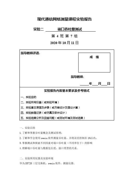
现代通信网络测量课程实验报告实验二端口吞吐量测试第4班第7组2020年10月11日一、实验目的1.了解和掌握吞吐量概念及测试原理;2.了解和学会使用renix软件测量吞吐量,并将误差控制在1%以内;3.掌握测试和探索不同因素对端口吞吐量(不同单位下)的影响4.理解端口吞吐量与数据包长度,接口类型的关系。
二、实验所用仪器及实验环境华为S5720三层交换机,renix软件,测量仪器。
三、实验基本原理及步骤 基本测量方法如下图所示:DUT测试仪器网线本实验基于RFC2544协议文件测量端口转发时延,对时延的定义如下图所示: Throughout :通过renix 软件配置数据帧,我们可以配置的变量有:数据包长度、接口类型。
在不同的接口类型下分别测试,测试方法是通过不断减小负载直至不丢包,得到在在不丢包情况下的最大传输速率,即吞吐量根据RFC2544,根据接口类型有不同的数据包长度可供选择。
在本实验中,以太网接口和ipv4接口的数据包的长度有如下选择:64, 128, 256, 512, 1024, 1280, 1518(字节)。
本实验的重点为“如何将误差控制在1%以内”,方法如下:当负载减小到无丢包时,根据已知数据可以判断实际吞吐量的大致范围,并根据实际吞吐量的范围,确定出误差在1%时的波动范围。
因此,当有丢包和无丢包对应的负载差值小于波动范围时,既可确定在该情况下得到的吞吐量的误差小于1%。
四、实验数据记录(一) ipv4测量结果--测试数据包长度对转发时延的影响数据表长度分别取值如下(单位:字节):64 128 256 512 1024 1280 1518(其余参数:时戳位置:Head Head)64128负载69.4%时,不丢包负载70%时,丢包128负载69.4%时,不丢包负载70%,丢包256负载70%,不丢包负载70.6%,丢包512负载70%,不丢包负载70.6%,丢包1024负载70.6%,不丢包负载71.3%,丢包1280负载70.6%,不丢包负载71.3%,丢包1518负载70.6%,不丢包负载71.3%,丢包结果分析:帧长/字节有丢包无丢包6470.6% 70.0%12870.0% 69.4%25670.6% 70.0%51270.6% 70.0%102471.3% 70.6%128071.3% 70.6%151871.3% 70.6% 为更直观显示表中数据,绘图如下:由图知,帧长度为64、128、256、512、1024、1280、1518字节的数据流的吞吐量(bps )相等, 即吞吐量(bps )不随帧长的增加而变化。
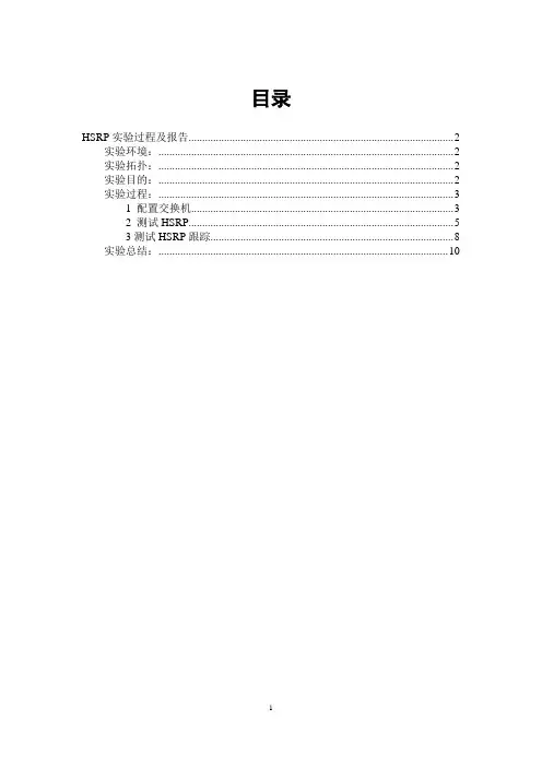
目录HSRP实验过程及报告 (2)实验环境: (2)实验拓扑: (2)实验目的: (2)实验过程: (3)1 配置交换机 (3)2 测试HSRP (5)3测试HSRP跟踪 (8)实验总结: (10)HSRP实验过程及报告实验环境:DynamipsGUI模拟器模拟出4台cisco3640三层交换机。
两台开启HSRP协议,设备之间使用Ethernetchannel绑定的两条线路互联。
其余两台交换机分别连接到这两台交换机。
实验拓扑:实验拓扑如图1实验目的:熟悉HSRP协议,验证HSRP网关冗余特性,测试HSRP抢占过程及HSRP接口跟踪。
实验过程:1 配置交换机在交换机SW1配置F0/0.F0/1接口加入channel-group 1 并将port-channel 1 配置为trunk模式。
SW1(config)#int range f0/0 - 1SW1(config-if-range)#channel-group 1 mode onCreating a port-channel interface Port-channel1SW1(config-if-range)#*Mar 1 01:23:58.639: %EC-5-BUNDLE: Interface Fa0/0 joined port-channel Po1 *Mar 1 01:23:58.935: %EC-5-BUNDLE: Interface Fa0/1 joined port-channel Po1 SW1(config-if-range)#*Mar 1 01:24:01.415: %LINEPROTO-5-UPDOWN: Line protocol on Interface Port-channel1, changed state to upSW1(config-if-range)#exitSW1(config)#int port-channel 1SW1(config-if)#switchport mode trunkSW1(config-if)#endSW1#sh etherchannel suFlags: D - down P - in port-channelI - stand-alone s - suspendedR - Layer3 S - Layer2U - in useGroup Port-channel Ports-----+------------+-----------------------------------------------------------1 Po1(SU) Fa0/0(P) Fa0/1(P)在交换机SW2上同样的配置。

交换机检测报告昨天,我们的公司收到了一份交换机检测报告。
这份报告详细地列出了我们公司网络中的每一个交换机的健康状况,帮助我们了解网络连接的稳定性,各个交换机的流量是否正常。
在这篇文章中,我想就这份交换机检测报告做一些详细的讨论。
首先,这份报告提供了非常详细的信息。
它列出了每个交换机的型号、容量、端口数量等等。
更重要的是,它还提供了每个交换机的连接状态。
这个信息对于我们来说非常重要。
因为只有当交换机连接正常,网络才能够正常工作。
如果一个交换机不工作了,那么它的所有连接都将中断,并且它还会成为网络中的瓶颈。
这就是为什么我们需要详细的连接状态信息。
其次,这份报告还提供了每个交换机的流量信息。
这个信息对于我们来说同样非常重要。
因为如果一个交换机的流量过大,那么它就会成为网络中的瓶颈。
当过多的数据包通过一个交换机时,就会出现延迟和丢包。
这些都会影响整个网络的性能。
因此,我们需要了解每个交换机的流量情况,以便及时解决问题。
最后,这份交换机检测报告还提供了一些警告信息。
这些警告信息通常涉及诸如过热、过载等问题。
如果我们忽略这些警告信息,就可能导致设备损坏,甚至导致整个网络崩溃。
因此,及时处理这些警告信息非常重要。
总的来说,这份交换机检测报告对于我们公司的网络管理来说非常重要。
它帮助我们了解每个交换机的健康状况,以便及时解决问题。
当我们需要添加设备或增加带宽时,这份报告还可以帮助我们选择正确的设备。
最重要的是,它可以帮助我们保持网络连接的稳定性,从而确保整个公司的正常运转。
交换机端口安全认证实验报告一、实验目的本实验旨在通过交换机端口安全认证,保障网络的信息安全。
通过实验,掌握交换机端口安全认证的原理和操作方法。
二、实验原理交换机端口安全认证是一种网络安全技术,用于限制未经授权设备接入网络。
其原理是利用交换机的MAC地址过滤功能,将非授权MAC地址的设备隔离或阻断,确保网络中只有授权设备能够接入。
三、实验环境1. 实验设备:一台交换机、若干台计算机设备2. 实验软件:网络配置工具、终端仿真软件四、实验步骤1. 配置交换机端口安全策略a. 进入交换机管理界面,并使用管理员账号登录。
b. 找到需要配置端口安全的端口,例如FastEthernet0/1。
c. 配置端口安全认证,设置允许连接设备的最大数量,例如2。
d. 配置端口安全认证方式为“限制”模式,即在达到最大设备数量时阻断后续设备连接。
e. 保存配置并退出管理界面。
2. 连接计算机设备a. 将一台计算机连接到已配置了端口安全的交换机端口上。
b. 打开终端仿真软件,配置计算机的IP地址和子网掩码。
c. 确保计算机与交换机端口连接正常。
3. 验证端口安全认证功能a. 将其他计算机设备依次连接到交换机端口。
b. 观察并记录交换机管理界面上的端口状态变化。
c. 当连入的设备数量达到最大允许数量时,验证交换机是否能够正确阻断后续设备连接。
五、实验结果与分析根据实验步骤进行操作后,我们观察到交换机管理界面上的端口状态发生了如下变化:1. 当第一台设备连接到交换机端口时,端口状态显示为“已连接”。
2. 当第二台设备连接到交换机端口时,端口状态仍显示为“已连接”,符合我们设定的最大允许设备数量为2。
3. 当第三台设备尝试连接到交换机端口时,端口状态显示为“已阻断”,交换机成功拦截了未授权设备连接。
通过以上观察,我们可以得出结论:交换机端口安全认证功能有效,能够根据设定的策略拦截未授权设备的连接,确保网络的安全性。
六、实验总结本次实验通过对交换机端口安全认证的配置和验证,详细了解了其原理和操作方法。

一、实验目的1. 了解端口扫描的基本概念和原理。
2. 掌握常用端口扫描工具的使用方法。
3. 学会分析端口扫描结果,识别潜在的安全风险。
二、实验环境1. 实验主机:Windows 10操作系统2. 实验工具:Nmap、Xscan、Nessus等端口扫描工具3. 实验对象:互联网上的目标主机三、实验内容1. 端口扫描概述2. 使用Nmap进行端口扫描3. 使用Xscan进行端口扫描4. 使用Nessus进行端口扫描5. 分析端口扫描结果四、实验步骤1. 端口扫描概述端口扫描是指通过网络发送特定数据包,检测目标主机上开放的服务端口的过程。
通过端口扫描,我们可以了解目标主机上运行的服务,从而评估其安全风险。
2. 使用Nmap进行端口扫描(1)安装Nmap:从官方网站下载Nmap安装包,按照提示进行安装。
(2)运行Nmap:在命令行中输入“nmap 目标IP”进行扫描。
(3)查看扫描结果:Nmap会生成一个文本文件,其中包含了扫描结果。
3. 使用Xscan进行端口扫描(1)安装Xscan:从官方网站下载Xscan安装包,按照提示进行安装。
(2)运行Xscan:在Xscan界面输入目标IP,点击“开始扫描”按钮。
(3)查看扫描结果:Xscan会生成一个HTML文件,其中包含了扫描结果。
4. 使用Nessus进行端口扫描(1)安装Nessus:从Tenable官方网站下载Nessus安装包,按照提示进行安装。
(2)运行Nessus:在Nessus界面输入目标IP,选择扫描模板,点击“开始扫描”按钮。
(3)查看扫描结果:Nessus会生成一个报告,其中包含了扫描结果。
5. 分析端口扫描结果(1)识别开放端口:根据扫描结果,找出目标主机上开放的端口。
(2)分析服务类型:根据开放端口,确定目标主机上运行的服务类型。
(3)评估安全风险:根据服务类型,评估目标主机的安全风险。
五、实验结果与分析1. 使用Nmap扫描目标主机,发现其开放了80、443、22、21等端口。

交换机测试报告引言:网络交换机作为网络通信设备中的重要组成部分,扮演着连接和分发网络数据的角色。
它的可靠性和性能对整个网络的工作效果有着直接的影响。
因此,对交换机进行定期的测试和评估是保证网络运行稳定的重要一环。
本报告将对某型号交换机进行测试,并分析测试结果。
一、测试环境概述:测试采用了实际生产环境,在大型企业网络中运行了某型号交换机。
网络中包含了多个部门和终端设备,各类数据流量相对复杂。
二、测试目标:1. 网络稳定性:测试交换机在高负载情况下的稳定性,包括流量控制、数据转发速度等。
2. 存储容量:测试交换机对MAC地址表和路由表等存储容量的支持和扩展性。
3. 交换机性能:测试交换机的吞吐量、传输延迟和数据包丢失率等性能指标,以确保其能够胜任现实网络环境中的各项任务。
4. 安全性:测试交换机的安全功能,包括访问控制、身份验证等。
三、测试步骤和结果:1. 稳定性测试:a. 测试交换机在高负载情况下的流量控制能力,结果显示交换机能够合理地分配和控制流量,避免出现堵塞和丢包现象。
b. 测试交换机在多个部门间的数据转发速度,结果显示交换机在毫秒级别的转发速度下,能够满足网络流量的需求。
c. 测试交换机故障恢复速度,结果显示交换机在故障恢复方面表现出色,迅速恢复到正常运行状态。
2. 存储容量测试:a. 测试交换机对MAC地址表的存储容量,结果显示交换机能够支持大规模MAC地址的动态学习和存储。
b. 测试交换机对路由表的存储容量,结果显示交换机能够灵活扩展路由表的容量,满足复杂网络环境的需要。
3. 交换机性能测试:a. 测试交换机的吞吐量,结果显示交换机能够达到理论最大值,并且不会因流量增加导致性能下降。
b. 测试交换机的传输延迟,结果显示交换机的延迟在可接受范围内,不会对网络应用产生明显的影响。
c. 测试交换机的数据包丢失率,结果显示交换机基本没有数据包丢失,保证了网络数据的完整性。
4. 安全性测试:a. 测试交换机的访问控制能力,结果显示交换机能够严格限制对网络资源的访问。
思科实验-实验1报告实验报告⼀、实验⽬的(本次实验所涉及并要求掌握的知识点)实验1.1:第 1 部分:检查DR 和BDR ⾓⾊变化第 2 部分:修改OSPF 优先级和强制选举实验1.2第 1 部分:配置基本交换机设置第 2 部分:通过思科PAgP 配置EtherChannel第 3 部分:配置802.3ad LACP EtherChannel第 4 部分:配置冗余EtherChannel 链路⼆、实验内容与设计思想(设计思路、主要数据结构、主要代码结构)实验1.1:在本练习中,您将检查DR 和BDR ⾓⾊并观察⽹络变化时⾓⾊的变化。
然后您将修改优先级以控制⾓⾊并强制进⾏新的选举。
最后,您将检验路由器是否充当所需⾓⾊。
实验1.2三台交换机已完成安装。
在交换机之间存在冗余上⾏链路。
通常只能使⽤这些链路中的⼀条;否则,可能会产⽣桥接环路。
但是,只使⽤⼀条链路只能利⽤⼀半可⽤带宽。
EtherChannel 允许将多达⼋条的冗余链路捆绑在⼀起成为⼀条逻辑链路。
在本实验中,您将配置端⼝聚合协议(PAgP)(Cisco EtherChannel 协议)和链路聚合控制协议(LACP)(EtherChannel 的IEEE 802.3ad 开放标准版本)。
三、实验使⽤环境(本次实验所使⽤的平台和相关软件)Cisco Packet Tracer四、实验步骤和调试过程(实验步骤、测试数据设计、测试结果分析)实验1.1:第⼀部分:检查DR 和BDR 的⾓⾊更改第 1 步:请等待,直到链路指⽰灯由琥珀⾊变为绿⾊。
当您在Packet Tracer 中⾸次打开⽂件时,您可能会注意到交换机的链路指⽰灯为琥珀⾊。
这些链路指⽰灯会保持琥珀⾊50 秒钟,在此期间,交换机会确认所连接的是路由器⽽不是交换机。
或者,您可以单击“Fast Forward Time”来跳过此过程。
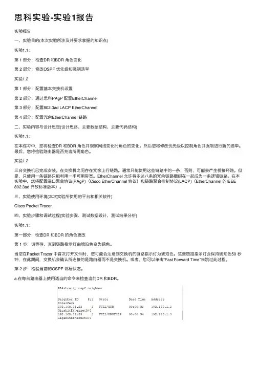
第 2 步:检验当前的OSPF 邻居状态。
a.在每台路由器上使⽤适当的命令来检查当前DR 和BDR。
端口实验报告1. 引言在计算机网络领域中,我们经常听到端口(Port)这个术语。
端口是指网络设备与其它设备进行通信时所使用的通道,类比于现实中的门窗。
在本实验中,我们将探索端口的概念、作用以及实际运用。
2. 端口的定义和作用端口是计算机上的一种抽象概念,它是应用程序与操作系统之间的接口。
通过端口,我们可以在计算机上同时运行多个网络应用程序,并且这些程序能够获得网络数据传输的资源。
端口可以有不同的编号,范围从0到65535,其中0到1023是保留端口,一般用于常见的服务和应用程序。
3. TCP/IP协议中的端口在TCP/IP协议簇中,端口分为两种类型:传输控制协议(TCP)端口和用户数据报协议(UDP)端口。
TCP端口用于建立可靠的、面向连接的网络连接,而UDP端口用于建立不可靠的、面向无连接的网络连接。
常见的TCP端口包括80端口(HTTP通信)、25端口(SMTP邮件传输)等,而UDP端口包括53端口(DNS域名解析)等。
4. 实验方法及结果本实验中,我们使用了一款网络抓包工具Wireshark来观察端口的实际运用。
我们首先在计算机上运行一个Web服务器,并将其监听在80端口。
接着,我们使用另一台计算机上的浏览器访问该服务器,并通过Wireshark抓取网络数据包。
通过分析抓包结果,我们发现浏览器与Web服务器之间的通信确实是通过80端口实现的。
5. 端口扫描与安全性在网络安全领域中,端口扫描是一种常见的技术,旨在识别目标主机上开放的端口,以便进行攻击或测试。
端口扫描可以帮助系统管理员评估网络的安全性,并及时发现可能存在的漏洞。
然而,恶意攻击者也可能利用端口扫描来寻找易受攻击的目标。
因此,在使用端口扫描技术时,必须遵守法律和伦理规范,否则可能涉及违法行为。
6. 端口转发及远程访问端口转发是一种将来自一个网络地址和端口的数据转发到另一个网络地址和端口的技术。
通过端口转发,我们可以实现远程主机的访问。
实验四端口聚合配置
一、实验目的
掌握EtherChannel的工作原理以信EtherChannel的配置。
二、实验描述
本项目以两台2960交换机为例,交换机命名为Switch1和Switch2;两台交换机的F0/23和F0/24端口连接在一起,以解决单链路带宽低而导致的网络瓶颈问题,实现带宽增加和冗余链路的作用。
三、实现功能
通过EtherChannel(以太通道),两台交换机F0/23和F0/24端口连接的两条链路在正常情况下可以起到均衡分配流量的作用;在其中一条链路出现故障的情况下,可以把流量转移到其他链路上。
四、实验拓扑图
EtherChannel配置实验图如图所示。
五、实验步骤
首先配置一下pc的IP地址
在未配置PC机之前,ping不通
通过PC1的Terminal进入配置界面,输入配置代码
PC1配置完成,之后用相同的方式配置PC2
都配置完后可看相关配置
Switch1:
Switch2:
最后两个终端ping通
实验完成。
端口聚合也叫做以太通道(ethernet channel),主要用于交换机之间连接。
由于两个交换机之间有多条冗余链路的时候,STP会将其中的几条链路关闭,只保留一条,这样可以避免二层的环路产生。
但是,失去了路径冗余的优点,因为STP的链路切换会很慢,在50s左右。
使用以太通道的话,交换机会把一组物理端口联合起来,做为一个逻辑的通道,也就是channel-group,这样交换机会认为这个逻辑通道为一个端口。
这样有几个优点: 1. 带宽增加,带宽相当于组成组的端口的带宽总和。
2. 增加冗余,只要组内不是所有的端口都down掉,两个交换机之间仍然可以继续通信。
3. 负载均衡,可以在组内的端口上配置,使流量可以在这些端口上自动进行负载均衡。
在用的时候要注意:端口要在一个vlan里面,两边的全双工模式要一样,还有就是作用的端口个数不能是3和6,而且不能超过8个,比如:2,4,8。
网络拓扑如下:华为交换机上配置端口聚合的命令是:link-aggregation ethernet0/1 to ethernet0/2 both文档收集自网络,仅用于个人学习试验一:在switch2 上将fa0/12和fa0/16口用网线连接,如果此时,switch2上没有打开stp,则switch2上存在环路,如果此时switch1上loop-deteaction打开,则switch1上有如下告警信息:文档收集自网络,仅用于个人学习%Jan 1 23:13:03 2002 test-switch1 DRV/5/LOOP BACK:Slot=1;文档收集自网络,仅用于个人学习Loopback does exist on port 24, please check it如果在swicth1上将stp打开,则0/12口forwarding ,0/16口discarding,swicth1将环路消除。
文档收集自网络,仅用于个人学习[test-switch2]display stp interface Ethernet 0/12Protocol mode: IEEE RSTPThe bridge ID (Pri.MAC): 32768.00e0-fc23-79faThe bridge times: Hello Time 2 sec, Max Age 20 sec, Forward Delay 15 secRoot bridge ID(Pri.MAC): 32768.00e0-fc23-34a9Root path cost: 180Bridge bpdu-protection: disabledTimeout factor: 3Port 12 (Ethernet0/12) of bridge is ForwardingPort spanning tree protocol: enabledPort role: DesignatedPortPort path cost: 200Port priority: 128Designated bridge ID(Pri.MAC): 32768.00e0-fc23-79faThe Port is a non-edged portConnected to a point-to-point LAN segmentMaximum transmission limit is 3 Packets / hello timeTimes: Hello Time 2 sec, Max Age 20 secForward Delay 15 sec, Message Age 1BPDU sent: 137TCN: 0, RST: 137, Config BPDU: 0BPDU received: 12TCN: 0, RST: 12, Config BPDU: 0[test-switch2]display stp interface Ethernet 0/16Protocol mode: IEEE RSTPThe bridge ID (Pri.MAC): 32768.00e0-fc23-79faThe bridge times: Hello Time 2 sec, Max Age 20 sec, Forward Delay 15 secRoot bridge ID(Pri.MAC): 32768.00e0-fc23-34a9Root path cost: 180Bridge bpdu-protection: disabledTimeout factor: 3Port 16 (Ethernet0/16) of bridge is DiscardingPort spanning tree protocol: enabledPort role: BackupPortPort path cost: 200Port priority: 128Designated bridge ID(Pri.MAC): 32768.00e0-fc23-79faThe Port is a non-edged portConnected to a point-to-point LAN segmentMaximum transmission limit is 3 Packets / hello timeTimes: Hello Time 2 sec, Max Age 20 secForward Delay 15 sec, Message Age 1BPDU sent: 3TCN: 0, RST: 3, Config BPDU: 0BPDU received: 149TCN: 0, RST: 149, Config BPDU: 0再次证实了loop-deteaction是针对下联端口环路的检测,而stp是针对网络拓扑环路的检测。
CiscoPort-Channel设置(链路聚合--重点)Port-Channel 的在实际⼯作中的主要作⽤是将两个或多个端⼝捆绑成为⼀个虚拟通道。
interface Port-channel1description port(1/0/5-6)switchport trunk encapsulation dot1qswitchport trunk allowed vlan 10switchport mode trunk!interface Port-channel2description port(1/0/7-8)switchport trunk encapsulation dot1qswitchport trunk allowed vlan 10switchport mode trunk!interface Port-channel3description port(1/0/9-10)switchport trunk encapsulation dot1qswitchport trunk allowed vlan 10switchport mode trunk!interface Port-channel4description port(1/0/11-12)shutdown以上是我在Cisco 3750上做的配置,其中:description port(1/0/5-6) 是对这个虚拟通道的描述,告知这个虚拟通道使⽤了端⼝1/0/ 的5和6端⼝switchport trunk encapsulation dot1q 是强制虚拟通道使⽤dot 1q 来封装数据包switchport trunk allowed vlan 10 是强制虚拟通道能够通过的VLAN,此例只有vlan10能通过此通道switchport mode trunk 是强制为 triuk 模式具体的命令如下:3750-route#configure terminal3750-route(config)#interface port-channel 13750-route(config-if)#switchport mode trunk3750-route(config-if)#switchport trunk encapsulation dot1q3750-route(config-if)#switchport trunk allowed vlan 103750-route(config-if)#description xxxxxx创建 port-channel 1 后,还需要在相应的端⼝上进⾏配置interface GigabitEthernet1/0/5description Port-channel-1switchport trunk encapsulation dot1qswitchport mode trunkchannel-group 1 mode on!interface GigabitEthernet1/0/6description Port-channel-1switchport trunk encapsulation dot1qswitchport mode trunkchannel-group 1 mode on此处特别要提⽰的是最后的⼀条命令channel-group 1 mode on 是 port-channel 1 可以调⽤此端⼝,换句话说:这个端⼝⾪属于 port-channel 1具体命令如下:3750-route#configure terminal3750-route(config)#interface range gigabitEthernet 1/0/5-63750-route(config-if)#switchport mode trunk3750-route(config-if)#switchport trunk encapsulation dot1q3750-route(config-if)#description xxxxxx3750-route(config-if)#channel-group 1 mode on3750-route(config-if-range)#speed 100 //配速率3750-route(config-if-range)#duplex full ////配速率3750-route(config)#port-channel load-balance dst-ip ///配负载模式端⼝聚合查看命令(排错常⽤命令)#查看端⼝聚合信息,正常情况Port-channel显⽰是SU,如果显⽰SD就不正常Switch#show etherchannel summary更具体的命令:Switch#sh etherchannel 3 summary查PO3 汇总信息,即绑定哪些接⼝做聚合1 Po1(SU) PAgP Fa0/23(P) Fa0/24(P)2 Po2(SU) PAgP Fa0/21(P) Fa0/22(P)#查看通道接⼝状况Switch#show etherchannel load-balance //查看负载信息Switch# show etherchannel port-channel //查看port-channel详细信息Switch#sh int trunk 查所有允许trunk 通道的VLAN更具体的命令:Switch#sh int port-channel 1 trunk 查po1 允许通过的vlan ,trunk 通道sh int etherchannel。
实验一交换机的配置一、VLAN的配置1.1实验目标1.掌握交换机基本信息的配置管理。
2.理解虚拟LAN(VLAN)基本配置;3.掌握一般交换机按端口划分VLAN的配置方法;4.掌握Tag VLAN配置方法。
1.2实验背景某公司新进一批交换机,公司内财务部、销售部的PC通过2台交换机实现通信;要求财务部和销售部的PC可以互通,但为了数据安全起见,销售部和财务部需要进行互相隔离,现要在交换机上做适当配置来实现这一目1.3 技术原理1.交换机的命令行操作模式主要包括:1)用户模式 Switch>2)特权模式 Switch#3)全局配置模式 Switch(config)#4)端口模式 Switch(config-if)#2. VLAN是指在一个物理网段内。
进行逻辑的划分,划分成若干个虚拟局域网,VLAN做大的特性是不受物理位置的限制,可以进行灵活的划分。
VLAN具备了一个物理网段所具备的特性。
相同VLAN内的主机可以相互直接通信,不同VLAN 间的主机之间互相访问必须经路由设备进行转发,广播数据包只可以在本VLAN 内进行广播,不能传输到其他VLAN中。
Port VLAN是实现VLAN的方式之一,它利用交换机的端口进行VALN的划分,一个端口只能属于一个VLAN。
Tag VLAN是基于交换机端口的另一种类型,主要用于是交换机的相同Vlan 内的主机之间可以直接访问,同时对不同Vlan的主机进行隔离。
Tag VLAN遵循IEEE802.1Q协议的标准,在使用配置了Tag VLAN的端口进行数据传输时,需要在数据帧内添加4个字节的8021.Q标签信息,用于标示该数据帧属于哪个VLAN,便于对端交换机接收到数据帧后进行准确的过滤。
1.4实验步骤1.新建Packet Tracer拓扑图;2.划分VLAN;3.将端口划分到相应VLAN中;4.测试图 1-1 VLAN拓扑图1.5实验结果:1.5.1对交换机进行配置1.5.2配置交换机:通过“show VLAN”命令,查看交换机VLAN的配置1.5.3划分两个VLAN ,VLAN10和VLAN20配置交换机,在pc0上使用ping命令。
修订历史记录目录1 概述....................................................................................4错误!未定义书签。
1.1 项目概述...............................................................错误!未定义书签。
41.2 术语与缩略语.........................................................错误!未定义书签。
1.3 参考与引用文档...................................................错误!未定义书签。
42 测试情况.............................................................................错误!未定义书签。
52.1 测试机构和人员 (5)2.2 测试结果......................................................................错误!未定义书签。
53 测试统计.............................................................................错误!未定义书签。
53.1 测试统计表..................................................................错误!未定义书签。
53.2 测试统计图..................................................................错误!未定义书签。
6 4测试评价................................................................................. 错误!未定义书签。
Port-Channel笔记
一、Port-Channel技术的意义。
1.增加带宽
通过技术手段将若干物理链路捆绑成一条逻辑链路,使单条链路的带宽增加。
2.物理线路冗余
在捆绑好的Port-Channel中,物理链路会产生冗余效果。
当其中一条物理链路断掉
时,整条逻辑链路不会产生中断,仅仅带宽变小。
二、Port-Channel对设备要求。
Port-Channel技术对设备有一定的要求。
1.端口均为全双工模式;
2.端口速率相同;
3.端口的类型必须一样,比如同为以太口或同为光纤口;
4.端口同为access 端口并且属于同一个vlan 或同为trunk 端口;
5.如果端口为trunk 端口,则其allowed vlan 和native vlan属性也应该相同。
三、Channel-Group的五种模式。
Channel-Group分为五种模式On、Active、Passive、Desirable、Auto。
其中按照协议类型不同分为三类。
1.无协议
无协议的Channel-Group两端均使用On模式。
链路两端之间不发送任何关于
Port-Channel的协商数据包。
仅在本地对端口进行属性比较。
CP协议
LACP协议的Channel-Group有两种模式。
A.Active – Active
两端均为Active模式时,两端会相互发送端口绑定的协商数据包。
当一端收到
另一端的协商数据包时,则确认该端口可以加入Port-Channel的链路中。
B.Active – Passive
Passive仅接收LACP协议的协商数据包,并不对其加以反馈。
当Passive端收到
Active端发送的数据包时,则表示该物理链路符合加入Port-Channel链路聚合的
条件。
3.PAgP协议
A.Desirable – Desirable
两端均为Desirable模式时,将会相互发送PAgP的协商数据包。
如果端口收到
对端发送的数据包,则表示该条链路符合加入Port-Channel的条件。
B.Desirable – Auto
Auto模式表示该端口仅接收PAgP协议的数据包,单并不会加以反馈。
与LACP
协议类似。
其中LACP是公有协议,而PAgP是思科的私有协议。
在思科的官方配置文档中,建议工程师在配置思科设备时优先使用PAgP协议。
四、Port-Channel链路的负载均衡。
Port-Channel的负载均衡和我们熟知的负载均衡有所不同。
Port-Channel的负载均衡一般按照类型分为源IP、源MAC、目的IP、目的MAC、源和目的IP、源和目的MAC。
这里以源IP为例。
当IP为192.168.1.100的主机发送数据包穿过Port-Channel时,从F0/1端口通过。
那么只要是192.168.1.100的主机通过Port-Channel的,只能从F0/1端口通过。
这时如
果出现另一台主机192.168.2.100的数据包要通过Port-Channel,将会走F0/2端口通过。
其他的数据包将会按照源IP此规律通过。
五、Port-Channel创建模板
二层:
interface Port-channel1
switchport
switchport trunk encapsulation dot1q
switchport trunk allowed vlan 20
switchport mode trunk
!
interface Ethernet0/0
switchport trunk encapsulation dot1q
switchport mode trunk
duplex auto
channel-group 1 mode on/Active/Passive/Desirable/Auto
!
interface Ethernet0/1
switchport trunk encapsulation dot1q
switchport mode trunk
duplex auto
channel-group 1 mode on/Active/Passive/Desirable/Auto
三层:
interface Port-channel1
no switchport
ip address 192.168.1.1 255.255.255.0
!
interface Ethernet0/0
no switchport
duplex auto
channel-group 1 mode on/Active/Passive/Desirable/Auto
!
interface Ethernet0/1
no switchport
duplex auto
channel-group 1 mode on/Active/Passive/Desirable/Auto
六、Port-Channel常用命令。
Show etherchannel summary
查看Port-Channel的状态
port-channel load-balancedst-ip/ dst-mac/src-dst-ip/ src-dst-mac/ src-ip/ src-mac
配置port-channel的负载均衡
Channel-protocol lacp/pagp
配置端口使用lacp/pagp协议,此命令在大多数设备上不需要配置
Lacp port-priority<0-65535>
调整端口的lacp优先级,默认值为32768
pagp port-priority<0-255>
配置端口的pagp优先级,默认值为128
七、Port-Channel故障。
在发生故障的时候各模式的现象是不通的。
A.物理链路中断
当物理链路发生中断的时候,各类的port-channel模式都能其到良好的备份冗余的
功能。
能够快速的启用其他备份线路。
各模式的可靠性都很高。
B.人为配置错误
a)无协议
两端都是用on模式的网络环境中,设备会按照端口号选举小的作为master。
如果master端口因为配置原因出现错误,整条的port-channel会中断。
如果其他端口因为配置原因出现错误,那么有可能不会影响到port-channel链
路的数据传输。
b)LACP
在使用LACP的port-channel中,如果因为人为配置原因发生错误。
两端设备都会亮黄色的告警灯,如果有数据从该端口进行传输,网络会中断大
约90秒。
c)PAgP
在使用PAgP的port-channel中,如果一个物理端口因为人为配置导致错误。
在配置错误的那一端的端口会有黄色的告警灯。
如果网络中有数据传输,不会
有长时间的中断。
在测试中,大约1秒左右,网络数据传输恢复。