人脸识别文献翻译中英文
- 格式:pdf
- 大小:2.01 MB
- 文档页数:15
支持人脸识别的英语作文英文回答:In our modern, tech-savvy world, face recognition technology has emerged as a transformative tool with immense potential. With its ability to accurately identify individuals, it promises to revolutionize various aspects of our lives. As someone who firmly believes in its benefits, I enthusiastically endorse the adoption of face recognition technology.From enhancing security measures to streamlining daily tasks, face recognition offers a plethora of advantages. In a world marred by threats and vulnerabilities, it plays a crucial role in safeguarding our physical and digital spaces. The technology enables swift and accurate identification of individuals, ensuring only authorized personnel gain access to sensitive areas or online platforms.Beyond security applications, face recognition also enhances convenience. Imagine walking into a store and having the system identify you, providing personalized recommendations based on your preferences. It eliminates the need for tedious password inputs or remembering multiple identification cards. In the healthcare sector, face recognition can expedite patient registration and improve treatment accuracy by accessing medical records instantly.Moreover, face recognition has the potential to foster inclusivity and bridge societal divides. By eliminating language barriers and accommodating individuals with disabilities, it ensures everyone has equal access to essential services. It empowers the visually impaired to navigate public spaces confidently and enables non-native speakers to communicate seamlessly.Additionally, face recognition technology can contribute to scientific research and innovation. It aids in identifying patterns and correlations within large datasets,leading to groundbreaking discoveries in fields such as medicine and genetics. By recognizing facial expressions and emotions, it can assist in understanding human behavior and developing therapies for mental health disorders.Of course, concerns regarding privacy and potential misuse must be addressed. However, with robust ethical frameworks and stringent regulations, we can harness the benefits of face recognition technology while safeguarding individual rights. It is essential to ensure responsible implementation and prevent unauthorized access to sensitive information.In conclusion, face recognition technology holds immense promise for transforming our lives. Its ability to enhance security, streamline tasks, foster inclusivity, and contribute to research makes it a valuable tool in our technological arsenal. By embracing its potential while addressing ethical considerations, we can unlock the transformative power of face recognition and shape a brighter future for all.中文回答:在我们这个科技发达的现代社会,人脸识别技术已经成为一种极具潜力的变革性工具。
人脸识别英文专业词汇gallery set参考图像集Probe set=test set测试图像集face renderingFacial Landmark Detection人脸特征点检测3D Morphable Model 3D形变模型AAM (Active Appearance Model)主动外观模型Aging modeling老化建模Aging simulation老化模拟Analysis by synthesis 综合分析Aperture stop孔径光标栏Appearance Feature表观特征Baseline基准系统Benchmarking 确定基准Bidirectional relighting 双向重光照Camera calibration摄像机标定(校正)Cascade of classifiers 级联分类器face detection 人脸检测Facial expression面部表情Depth of field 景深Edgelet 小边特征Eigen light-fields本征光场Eigenface特征脸Exposure time曝光时间Expression editing表情编辑Expression mapping表情映射Partial Expression Ratio Image局部表情比率图(,PERI) extrapersonal variations类间变化Eye localization,眼睛定位face image acquisition 人脸图像获取Face aging人脸老化Face alignment人脸对齐Face categorization人脸分类Frontal faces 正面人脸Face Identification人脸识别Face recognition vendor test人脸识别供应商测试Face tracking人脸跟踪Facial action coding system面部动作编码系统Facial aging面部老化Facial animation parameters脸部动画参数Facial expression analysis人脸表情分析Facial landmark面部特征点Facial Definition Parameters人脸定义参数Field of view视场Focal length焦距Geometric warping几何扭曲Street view街景Head pose estimation头部姿态估计Harmonic reflectances谐波反射Horizontal scaling水平伸缩Identification rate识别率Illumination cone光照锥Inverse rendering逆向绘制技术Iterative closest point迭代最近点Lambertian model朗伯模型Light-field光场Local binary patterns局部二值模式Mechanical vibration机械振动Multi-view videos多视点视频Band selection波段选择Capture systems获取系统Frontal lighting正面光照Open-set identification开集识别Operating point操作点Person detection行人检测Person tracking行人跟踪Photometric stereo光度立体技术Pixellation像素化Pose correction姿态校正Privacy concern隐私关注Privacy policies隐私策略Profile extraction轮廓提取Rigid transformation刚体变换Sequential importance sampling序贯重要性抽样Skin reflectance model,皮肤反射模型Specular reflectance镜面反射Stereo baseline 立体基线Super-resolution超分辨率Facial side-view面部侧视图Texture mapping纹理映射Texture pattern纹理模式Rama Chellappa读博计划:1.完成先前关于指纹细节点统计建模的相关工作。
中英文对照外文翻译文献(文档含英文原文和中文翻译)Elastic image matchingAbstractOne fundamental problem in image recognition is to establish the resemblance of two images. This can be done by searching the best pixel to pixel mapping taking into account monotonicity and continuity constraints. We show that this problem is NP-complete by reduction from 3-SAT, thus giving evidence that the known exponential time algorithms are justified, but approximation algorithms or simplifications are necessary.Keywords: Elastic image matching; Two-dimensional warping; NP-completeness 1. IntroductionIn image recognition, a common problem is to match two given images, e.g. when comparing an observed image to given references. In that pro-cess, elastic image matching, two-dimensional (2D-)warping (Uchida and Sakoe, 1998) or similar types of invariant methods (Keysers et al., 2000) can be used. For this purpose, we can define cost functions depending on the distortion introduced in the matching andsearch for the best matching with respect to a given cost function. In this paper, we show that it is an algorithmically hard problem to decide whether a matching between two images exists with costs below a given threshold. We show that the problem image matching is NP-complete by means of a reduction from 3-SAT, which is a common method of demonstrating a problem to be intrinsically hard (Garey and Johnson, 1979). This result shows the inherent computational difficulties in this type of image comparison, while interestingly the same problem is solvable for 1D sequences in polynomial time, e.g. the dynamic time warping problem in speech recognition (see e.g. Ney et al., 1992). This has the following implications: researchers who are interested in an exact solution to this problem cannot hope to find a polynomial time algorithm, unless P=NP. Furthermore, one can conclude that exponential time algorithms as presented and extended by Uchida and Sakoe (1998, 1999a,b, 2000a,b) may be justified for some image matching applications. On the other hand this shows that those interested in faster algorithms––e.g. for pattern recognition purposes––are right in searching for sub-optimal solutions. One method to do this is the restriction to local optimizations or linear approximations of global transformations as presented in (Keysers et al., 2000). Another possibility is to use heuristic approaches like simulated annealing or genetic algorithms to find an approximate solution. Furthermore, methods like beam search are promising candidates, as these are used successfully in speech recognition, although linguistic decoding is also an NP-complete problem (Casacuberta and de la Higuera, 1999). 2. Image matchingAmong the varieties of matching algorithms,we choose the one presented by Uchida and Sakoe(1998) as a starting point to formalize the problem image matching. Let the images be given as(without loss of generality) square grids of size M×M with gray values (respectively node labels)from a finite alphabet &={1,…,G}. To define thed:&×&→N , problem, two distance functions are needed,one acting on gray valuesg measuring the match in gray values, and one acting on displacement differences :Z×Z→N , measuring the distortion introduced by t he matching. For these distance ddfunctions we assume that they are monotonous functions (computable in polynomial time) of the commonly used squared Euclid-ean distance, i.ed g (g 1,g 2)=f 1(||g 1-g 2||²)and d d (z)=f 2(||z||²) monotonously increasing. Now we call the following optimization problem the image matching problem (let µ={1,…M} ).Instance: The pair( A ; B ) of two images A and B of size M×M .Solution: A mapping function f :µ×µ→µ×µ.Measure:c (A,B,f )=),(),(j i f ij g B Ad ∑μμ⨯∈),(j i+∑⨯-⋅⋅⋅∈+-+μ}1,{1,),()))0,1(),(())0,1(),(((M j i d j i f j i f dμ⨯-⋅⋅⋅∈}1,{1,),(M j i +∑⋅⋅⋅⨯∈+-+1}-M ,{1,),()))1,0(),(())1,0(),(((μj i d j i f j i f d 1}-M ,{1,),(⋅⋅⋅⨯∈μj iGoal:min f c(A,B,f).In other words, the problem is to find the mapping from A onto B that minimizes the distance between the mapped gray values together with a measure for the distortion introduced by the mapping. Here, the distortion is measured by the deviation from the identity mapping in the two dimensions. The identity mapping fulfills f(i,j)=(i,j),and therefore ,f((i,j)+(x,y))=f(i,j)+(x,y)The corresponding decision problem is fixed by the followingQuestion:Given an instance of image matching and a cost c′, does there exist a ma pping f such that c(A,B,f)≤c′?In the definition of the problem some care must be taken concerning the distance functions. For example, if either one of the distance functions is a constant function, the problem is clearly in P (for d g constant, the minimum is given by the identity mapping and for d d constant, the minimum can be determined by sorting all possible matching for each pixel by gray value cost and mapping to one of the pixels with minimum cost). But these special cases are not those we are concerned with in image matching in general.We choose the matching problem of Uchida and Sakoe (1998) to complete the definition of the problem. Here, the mapping functions are restricted by continuity and monotonicity constraints: the deviations from the identity mapping may locally be at most one pixel (i.e. limited to the eight-neighborhood with squared Euclidean distance less than or equal to 2). This can be formalized in this approach bychoosing the functions f1,f2as e.g.f 1=id,f2(x)=step(x):=⎩⎨⎧.2,)10(,2,0>≤⋅xGxMM3. Reduction from 3-SAT3-SAT is a very well-known NP-complete problem (Garey and Johnson, 1979), where 3-SAT is defined as follows:Instance: Collection of clauses C={C1,···,CK} on a set of variables X={x1, (x)L}such that each ckconsists of 3 literals for k=1,···K .Each literal is a variable or the negation of a variable.Question:Is there a truth assignment for X which satisfies each clause ck, k=1,···K ?The dependency graph D(Ф)corresponding to an instance Ф of 3-SAT is defined to be the bipartite graph whose independent sets are formed by the set of clauses Cand the set of variables X .Two vert ices ck and x1are adjacent iff ckinvolvesx 1or-xL.Given any 3-SAT formula U, we show how to construct in polynomial time anequivalent image matching problem l(Ф)=(A(Ф),B(Ф)); . The two images of l (Ф)are similar according to the cost function (i.e.f:c(A(Ф),B(Ф),f)≤0) iff the formulaФ is satisfiable. We perform the reduction from 3-SAT using the following steps:• From the formula Ф we construct the dependency graph D(Ф).• The dependency graph D(Ф)is drawn in the plane.• The drawing of D(Ф)is refined to depict the logical behaviour of Ф , yielding two images(A(Ф),B(Ф)).For this, we use three types of components: one component to represent variables of Ф , one component to represent clauses of Ф, and components which act as interfaces between the former two types. Before we give the formal reduction, we introduce these components.3.1. Basic componentsFor the reduction from 3-SAT we need five components from which we will construct the in-stances for image matching , given a Boolean formula in 3-DNF,respectively its graph. The five components are the building blocks needed for the graph drawing and will be introduced in the following, namely the representations of connectors,crossings, variables, and clauses. The connectors represent the edges and have two varieties, straight connectors and corner connectors. Each of the components consists of two parts, one for image A and one for image B , where blank pixels are considered to be of the‘background ’color.We will depict possible mappings in the following using arrows indicating the direction of displacement (where displacements within the eight-neighborhood of a pixel are the only cases considered). Blank squares represent mapping to the respective counterpart in the second image.For example, the following displacements of neighboring pixels can be used with zero cost:On the other hand, the following displacements result in costs greater than zero:Fig. 1 shows the first component, the straight connector component, which consists of a line of two different interchanging colors,here denoted by the two symbols◇and□. Given that the outside pixels are mapped to their respe ctive counterparts and the connector is continued infinitely, there are two possible ways in which the colored pixels can be mapped, namely to the left (i.e. f(2,j)=(2,j-1)) or to the right (i.e. f(2,j)=(2,j+1)),where the background pixels have different possibilities for the mapping, not influencing the main property of the connector. This property, which justifies the name ‘connector ’, is the following: It is not possible to find a mapping, which yields zero cost where the relative displacements of the connector pixels are not equal, i.e. one always has f(2,j)-(2,j)=f(2,j')-(2,j'),which can easily be observed by induction over j'.That is, given an initial displacement of one pixel (which will be ±1 in this context), the remaining end of the connector has the same displacement if overall costs of the mapping are zero. Given this property and the direction of a connector, which we define to be directed from variable to clause, wecan define the state of the connector as carrying the‘true’truth value, if the displacement is 1 pixel in the direction of the connector and as carrying the‘false’ truth value, if the displacement is -1 pixel in the direction of the connector. This property then ensures that the truth value transmitted by the connector cannot change at mappings of zero cost.Image A image Bmapping 1 mapping 2Fig. 1. The straight connector component with two possible zero cost mappings.For drawing of arbitrary graphs, clearly one also needs corners,which are represented in Fig. 2.By considering all possible displacements which guarantee overall cost zero, one can observe that the corner component also ensures the basic connector property. For example, consider the first depicted mapping, which has zero cost. On the other hand, the second mapping shows, that it is not possible to construct a zero cost mapping with both connectors‘leaving’the component. In that case, the pixel at the position marked‘? ’either has a conflict (that i s, introduces a cost greater than zero in the criterion function because of mapping mismatch) with the pixel above or to the right of it,if the same color is to be met and otherwise, a cost in the gray value mismatch term is introduced.image A image Bmapping 1 mapping 2Fig. 2. The corner connector component and two example mappings.Fig. 3 shows the variable component, in this case with two positive (to the left) and one negated output (to the right) leaving the component as connectors. Here, a fourth color is used, denoted by ·.This component has two possible mappings for thecolored pixels with zero cost, which map the vertical component of the source image to the left or the right vertical component in the target image, respectively. (In both cases the second vertical element in the target image is not a target of the mapping.) This ensures±1 pixel relative displacements at the entry to the connectors. This property again can be deducted by regarding all possible mappings of the two images.The property that follows (which is necessary for the use as variable) is that all zero cost mappings ensure that all positive connectors carry the same truth value,which is the opposite of the truth value for all the negated connectors. It is easy to see from this example how variable components for arbitrary numbers of positive and negated outputs can be constructed.image A image BImage C image DFig. 3. The variable component with two positive and one negated output and two possible mappings (for true and false truth value).Fig. 4 shows the most complex of the components, the clause component. This component consists of two parts. The first part is the horizontal connector with a 'bend' in it to the right.This part has the property that cost zero mappings are possible for all truth values of x and y with the exception of two 'false' values. This two input disjunction,can be extended to a three input dis-junction using the part in the lower left. If the z connector carries a 'false' truth value, this part can only be mapped one pixel downwards at zero cost.In that case the junction pixel (the fourth pixel in the third row) cannot be mapped upwards at zero cost and the 'two input clause' behaves as de-scribed above. On the other hand, if the z connector carries a 'true' truth value, this part can only be mapped one pixel upwards at zero cost,and the junction pixel can be mapped upwards,thus allowing both x and y to carry a 'false' truth value in a zero cost mapping. Thus there exists a zero cost mapping of the clause component iff at least one of the input connectors carries a truth value.image Aimage B mapping 1(true,true,false)mapping 2 (false,false,true,)Fig. 4. The clause component with three incoming connectors x, y , z and zero cost mappings forthe two cases(true,true,false)and (false, false, true).The described components are already sufficient to prove NP-completeness by reduction from planar 3-SAT (which is an NP-complete sub-problem of 3-SAT where the additional constraints on the instances is that the dependency graph is planar),but in order to derive a reduction from 3-SAT, we also include the possibility of crossing connectors.Fig. 5 shows the connector crossing, whose basic property is to allow zero cost mappings if the truth–values are consistently propagated. This is assured by a color change of the vertical connector and a 'flexible' middle part, which can be mapped to four different positions depending on the truth value distribution.image Aimage Bzero cost mappingFig. 5. The connector crossing component and one zero cost mapping.3.2. ReductionUsing the previously introduced components, we can now perform the reduction from 3-SAT to image matching .Proof of the claim that the image matching problem is NP-complete:Clearly, the image matching problem is in NP since, given a mapping f and two images A and B ,the computation of c(A,B,f)can be done in polynomial time. To prove NP-hardness, we construct a reduction from the 3-SAT problem. Given an instance of 3-SAT we construct two images A and B , for which a mapping of cost zero exists iff all the clauses can be satisfied.Given the dependency graph D ,we construct an embedding of the graph into a 2D pixel grid, placing the vertices on a large enough distance from each other (say100(K+L)² ).This can be done using well-known methods from graph drawing (see e.g.di Battista et al.,1999).From this image of the graph D we construct the two images A and B , using the components described above.Each vertex belonging to a variable is replaced with the respective parts of the variable component, having a number of leaving connectors equal to the number of incident edges under consideration of the positive or negative use in the respective clause. Each vertex belonging to a clause is replaced by the respective clause component,and each crossing of edges is replaced by the respective crossing component. Finally, all the edges are replaced with connectors and corner connectors, and the remaining pixels inside the rectangular hull of the construction are set to the background gray value. Clearly, the placement of the components can be done in such a way that all the components are at a large enough distance from each other, where the background pixels act as an 'insulation' against mapping of pixels, which do not belong to the same component. It can be easily seen, that the size of the constructed images is polynomial with respect to the number of vertices and edges of D and thus polynomial in the size of the instance of 3-SAT, at most in the order (K+L)².Furthermore, it can obviously be constructed in polynomial time, as the corresponding graph drawing algorithms are polynomial.Let there exist a truth assignment to the variables x1,…,xL, which satisfies allthe clauses c1,…,cK. We construct a mapping f , that satisfies c(f,A,B)=0 asfollows.For all pixels (i, j ) belonging to variable component l with A(i,j)not of the background color,set f(i,j)=(i,j-1)if xlis assigned the truth value 'true' , set f(i,j)=(i,j+1), otherwise. For the remaining pixels of the variable component set A(i,j)=B(i,j),if f(i,j)=(i,j), otherwise choose f(i,j)from{(i,j+1),(i+1,j+1),(i-1,j+1)}for xl'false' respectively from {(i,j-1),(i+1,j-1),(i-1,j-1)}for xl'true ',such that A(i,j)=B(f(i,j)). This assignment is always possible and has zero cost, as can be easily verified.For the pixels(i,j)belonging to (corner) connector components,the mapping function can only be extended in one way without the introduction of nonzero cost,starting from the connection with the variable component. This is ensured by thebasic connector property. By choosing f (i ,j )=(i,j )for all pixels of background color, we obtain a valid extension for the connectors. For the connector crossing components the extension is straight forward, although here ––as in the variable mapping ––some care must be taken with the assign ment of the background value pixels, but a zero cost assignment is always possible using the same scheme as presented for the variable mapping.It remains to be shown that the clause components can be mapped at zero cost, if at least one of the input connectors x , y , z carries a ' true' truth value.For a proof we regard alls even possibilities and construct a mapping for each case. In thedescription of the clause component it was already argued that this is possible,and due to space limitations we omit the formalization of the argument here.Finally, for all the pixels (i ,j )not belonging to any of the components, we set f (i ,j )=(i ,j )thus arriving at a mapping function which has c (f ,A ,B )=0。
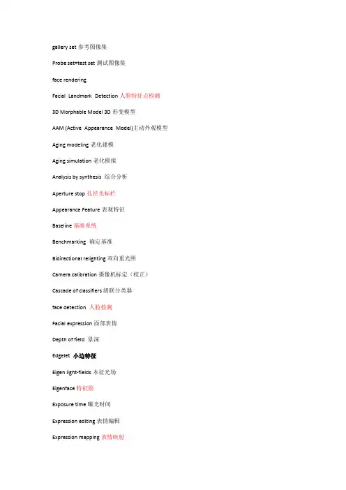
gallery set参考图像集Probe set=test set测试图像集face renderingFacial Landmark Detection人脸特征点检测3D Morphable Model 3D形变模型AAM (Active Appearance Model)主动外观模型Aging modeling老化建模Aging simulation老化模拟Analysis by synthesis 综合分析Aperture stop孔径光标栏Appearance Feature表观特征Baseline基准系统Benchmarking 确定基准Bidirectional relighting 双向重光照Camera calibration摄像机标定(校正)Cascade of classifiers 级联分类器face detection 人脸检测Facial expression面部表情Depth of field 景深Edgelet 小边特征Eigen light-fields本征光场Eigenface特征脸Exposure time曝光时间Expression editing表情编辑Expression mapping表情映射Partial Expression Ratio Image局部表情比率图(,PERI) extrapersonal variations类间变化Eye localization,眼睛定位face image acquisition 人脸图像获取Face aging人脸老化Face alignment人脸对齐Face categorization人脸分类Frontal faces 正面人脸Face Identification人脸识别Face recognition vendor test人脸识别供应商测试Face tracking人脸跟踪Facial action coding system面部动作编码系统Facial aging面部老化Facial animation parameters脸部动画参数Facial expression analysis人脸表情分析Facial landmark面部特征点Facial Definition Parameters人脸定义参数Field of view视场Focal length焦距Geometric warping几何扭曲Street view街景Head pose estimation头部姿态估计Harmonic reflectances谐波反射Horizontal scaling水平伸缩Identification rate识别率Illumination cone光照锥Inverse rendering逆向绘制技术Iterative closest point迭代最近点Lambertian model朗伯模型Light-field光场Local binary patterns局部二值模式Mechanical vibration机械振动Multi-view videos多视点视频Band selection波段选择Capture systems获取系统Frontal lighting正面光照Open-set identification开集识别Operating point操作点Person detection行人检测Person tracking行人跟踪Photometric stereo光度立体技术Pixellation像素化Pose correction姿态校正Privacy concern隐私关注Privacy policies隐私策略Profile extraction轮廓提取Rigid transformation刚体变换Sequential importance sampling序贯重要性抽样Skin reflectance model,皮肤反射模型Specular reflectance镜面反射Stereo baseline 立体基线Super-resolution超分辨率Facial side-view面部侧视图Texture mapping纹理映射Texture pattern纹理模式Rama Chellappa读博计划:完成先前关于指纹细节点统计建模的相关工作。
Sensing Human Activity:GPS Tracking感应人类活动:GPS跟踪Stefan van der Spek1,*,Jeroen van Schaick1,Peter de Bois1,2and Remco de Haan1Abstract:The enhancement of GPS technology enables the use of GPS devices not only as navigation and orientation tools,but also as instruments used to capture travelled routes:assensors that measure activity on a city scale or the regional scale.TU Delft developed aprocess and database architecture for collecting data on pedestrian movement in threeEuropean city centres,Norwich,Rouen and Koblenz,and in another experiment forcollecting activity data of13families in Almere(The Netherlands)for one week.Thequestion posed in this paper is:what is the value of GPS as‘sensor technology’measuringactivities of people?The conclusion is that GPS offers a widely useable instrument tocollect invaluable spatial-temporal data on different scales and in different settings addingnew layers of knowledge to urban studies,but the use of GPS-technology and deploymentof GPS-devices still offers significant challenges for future research.摘要:增强GPS技术支持使用GPS设备不仅作为导航和定位工具,但也为仪器用来捕捉旅行路线:作为传感器,测量活动在一个城市或区域范围内规模。
外文标题:Face Recognition-Based Mobile Automatic Classroom Attendance Management System外文作者:Refik Samet,Muhammed Tanriverdi文献出处: 2018 International Conference on Cyberworlds (如觉得年份太老,可改为近2年,毕竟很多毕业生都这样做)英文2937单词,20013字符(字符就是印刷符),中文4819汉字。
Face Recognition-Based Mobile Automatic ClassroomAttendance Management System Abstract—Classroom attendance check is a contributing factor to student participation and the final success in the courses. Taking attendance by calling out names or passing around an attendance sheet are both time-consuming, and especially the latter is open to easy fraud. As an alternative, RFID, wireless, fingerprint, and iris and face recognition-based methods have been tested and developed for this purpose. Although these methods have some pros, high system installation costs are the main disadvantage. The present paper aims to propose a face recognition-based mobile automatic classroom attendance management system needing no extra equipment. To this end, a filtering system based on Euclidean distances calculated by three face recognition techniques, namely Eigenfaces, Fisherfaces and Local Binary Pattern, has been developed for face recognition. The proposed system includes three different mobile applications for teachers, students, and parents to be installed on their smart phones to manage and perform the real-time attendance-taking process. The proposed system was tested among students at Ankara University, and the results obtained were very satisfactory.Keywords—face detection, face recognition, eigenfaces, fisherfaces, local binary pattern, attendance management system, mobile application, accuracyI.INTRODUCTIONMost educational institutions are concerned with st udents’ participation in courses since student participation in the classroom leads to effective learning and increases success rates [1]. Also, a high participation rate in the classroom is a motivating factor for teachers and contributes to a suitable environment for more willing and informative teaching [2]. The most common practice known to increase attendance in a course is taking attendance regularly. There are two common ways to create attendance data. Some teachers prefer to call names and put marks for absence or presence. Other teachers prefer to pass around a paper signing sheet. After gathering the attendance data via either of these two methods, teachers manually enter the data into the existing system. However, those non-technological methods are not efficient ways since they are time- consuming and prone to mistakes/fraud. The present paper aims to propose an attendance-taking process via the existing technological infrastructure with some improvements. A face recognition-based mobile automatic classroom attendance management system has been proposed with a face recognition infrastructure allowing the use of smart mobile devices. In this scope, a filtering system based on Euclidean distances calculated by three face recognition techniques, namely Eigenfaces, Fisherfaces, and Local Binary Pattern (LBP), has been developedfor face recognition. The proposed system includes three different applications for teachers, students, and parents to be installed on their smart phones to manage and perform a real-time polling process, data tracking, and reporting. The data is stored in a cloud server and accessible from everywhere at any time. Web services are a popular way of communication for online systems, and RESTful is an optimal example of web services for mobile online systems [3]. In the proposed system, RESTful web services were used for communication among teacher, student, and parent applications and the cloud server. Attendance results are stored in a database and accessible by the teacher, student and parent mobile applications.The paper is organised as follows. Section II provides a brief literature survey. SectionIII introduces the proposed system, and section IV follows by implementation and results. The last section gives the main conclusions.II.LITERATURE SURVEYFingerprint reading systems have high installation costs. Furthermore, only one student at a time can use a portable finger recognition device, which makes it atime-consuming process [4]. In the case of a fixed finger recognition device at the entrance of the classroom, attendance-taking should be done under the teacher's supervision so that students do not leave after the finger recognition, which makes the process time-consuming for both the teacher and the students. In case of RFID card reading systems, attendance-taking is available via the cards distributed to students [5]. In such systems, students may resort to fraudulent methods by reading their friends' cards. Also, if a student forgets his/her card, a non- true absence may be saved in the system. The disadvantage of the classroom scanning systems with Bluetooth or beacon methods is that each student must carry a device. Because the field limit of the Bluetooth Low Energy (BLE) system cannot be determined, students who are not inthe classroom at the moment but are within the Bluetooth area limits may appear to be present in the attendance system [6]. There are different methods of classroom attendance monitoring using face recognition technology. One of these is a camera placed at the classroom entrance and the students entering the classroom are registered into the system by face recognition [7]. However, in this system students’faces could be recognised, although students can leave the classroom afterwards, and errors can occur in the polling information. Another method is the observation carried out with a camera placed in the classroom and the classroom image taken during the course. In this case, the cameras used in the system need to be changed frequently to keep producing better quality images. Therefore, this system is not very useful andcan become costly. In addition to all the aforementioned disadvantages, the most common disadvantage is that all these methods need extra equipment. The proposed system has been developed to address these disadvantages. The main advantages of the proposed system are flexible usage, no equipment costs, no wasted time, and easy accessibility.III.PROPOSED SYSTEMA.Architecture of the Proposed SystemThe proposed system's architecture based on mobility and flexibility is shown inFig.1.Figure 1. System ArchitectureThe system consists of three layers: Application Layer, Communication Layer, and Server Layer.Application Layer: In the application layer, there are three mobile applications connected to the cloud server by web services. a) Teacher Application: The teacher is the head of the system, so he/she has the privilege to access all the data. By his/her smart mobile device, he/she can take a photo of students in a classroom at any time. After the taking the photograph, the teacher can use this photo to register attendance. For this aim, the photo is sent to the cloud server for face detection and recognition processing. The results are saved into a database together with all the reachable data. The teacher gets a response by the mobile application and can immediately see the results. The teacher can also create a student profile, add a photo of each student, and add or remove a student to/from their class rosters. He/she can as well create and delete courses. Each course has a unique six- character code. The teacher can share this code with his/her students so they can access their attendance results via the student application. The teacher can access to all data and results based on each student's recognized photo stamped with a date. Additionally, an email message with attendance data of a class in Excel format can be requested, while the analytics of the attendance results is provided in the application. b) Student Application: Students can sign in courses with the teacher's email address and the six-character course code. They can add their photos by taking a photo or a 3-second long video. In case of errors, their uploaded photos can be deleted. Students can only see limited results of the attendance-taking process related to their attendance. To protect personal privacy, the class photos and detected portrait photos of each student can be accessed only by the teacher. If students are not in the classroom when an attendance-check is performed, they are notified of the attendance-check. In case of errors (if a student is present, but not detected by the system), he/she can notify the teacher so he/she can fix the problem. c) Family Application: Parents can see their children's attendanceresults for each class. Additional children profiles can be added into the system. Each parent is added to the student's application with name, surname, and email address. When a student adds his/her parents, they are automatically able to see the attendance results. They are also notified when their child is not in the classroom.2) Communication Layer: RESTful web services are used to communicate betweenthe applications and server layers. Requests are sent by the POST method. Each request is sent with a unique ID of the authorised user of the session. Only the authorised users can access and respond the the data to which they have right to access. Due to its flexibility and fast performance, JSON is used as the data format for web services response [8]. With this abstract web service layer, the system can easily be used for a new item in the application layer, such as web pages or a new mobile operating system.3)Server Layer: The server layer is responsible for handling the requests and sending the results to the client. Face detection and recognition algorithms are performed in this layer and more than 30 different web services are created for handling different requests from mobile applications.B.Face DetectionAccurate and efficient face detection algorithms improve the accuracy level of theface recognition systems. If a face is not detected correctly, the system will fail its operation, stop processing, and restart. Knowledge-based, feature-based,template-based, and statistics-based methods are used for face detection [9]. Since the classroom photo is taken under the teacher's control, pose variations could be limited to a small range. Viola-Jones face detection method with Ada- boost training is shown as the best choice for real-time class attendance systems [9, 10]. In the most basic sense, the desired objects are firstly found and introduced according to a certain algorithm. Afterwards, they are scanned to find matches with similar shapes [11].C.Face RecognitionThere are two basic classifications of face recognition based on image intensity: feature-based and appearance-based [12]. Feature-based approaches try to represent (approximate) the object as compilations of different features, for example, eyes, nose, chin, etc. In contrast, the appearance-based models only use the appearance captured by different two-dimensional views of the object-of-interest. Feature-based techniques are more time-consuming than appearance-based techniques. The real-time attendance management system requires low computational process time. Therefore, three appearance-based face recognition techniques such as Eigenfaces, Fisherfaces and LBP are used in the tested system. Fisherfaces and eigenfaces techniques have a varying success rate, depending on different challenges, like pose variation, illumination, or facial expression [13]. According to several previous studies, face recognition using LBP method gives very good results regarding speed and discrimination performance as well as in different lighting conditions [14, 15]. Euclidean distance is calculated by finding similarities between images for face recognition. A filtering system based on Euclidean distances calculated by Eigenfaces, Fisherfaces and LBP has been developed for face recognition. According to the developed system, firstly, minimum Euclidean distances of LBP, Fisherfaces andEigenfaces algorithms are evaluated in defined order. If the Euclidean distance of LBP algorithm is less than 40; else if Euclidean distance of Fisherfaces algorithm is less than 250; else if Euclidean distance of Eigenfaces algorithm is less than 1500, recognized face is recorded as the right match. Secondly, if the calculated Euclidean distances by the three methods are greater than the minimum Euclidean distances, the second level Euclidean distances (40-50 (for LBP), 250-400 (for Fisherfaces), 1500- 1800 (for Eigenfaces)) are evaluated in the same way. If the second level conditions are also not met, the filter returns the wrong match. Thirdly, if any two algorithms give the same match result, the match is recorded correctly. Finally, if no conditions are met, the priority is given to the LBP algorithm and the match is recorded correctly. The system’s specific architecture aimed for flexibility, mobility, and low-cost by requiring no extra equipment. At the same time, its objective was to provide access to all users at any time. The system thus offers a real-time attendance management system to all its users.IV.IMPLEMENTATION AND RESULTSThe following platform was used. The cloud server has a 2.5 GHz with 4-core CPU,8GB RAM, and 64-bit operating system capacity. Viola-Jones face detection algorithm and Eigenfaces, Fisherfaces and LBP face recognition algorithms were implemented based on OpenCV. Tests were done with both iOS and ANDROID.Forty different attendance monitoring tests were performed in a real classroom, including 11 students, and 264 students’ faces were detected. Tables I, II, and III show detection and recognition accuracy of all three different types of tested algorithms related to the Euclidean distance.Priority ordering for 3 algorithms was arranged according to accuracy rate for each interval. In test results, 123, 89, and 85 false recognitions were detected for Eigenfaces, Fisherfaces and LBP, respectively. By the help of the developed filtering system, the number of false recognitions decreased to 65. Out of 40 implemented attendance monitoring tests, 10 were conducted with 1 face photo of each student in database in Step-I, 20 were conducted when the number of face photos increased up to 3 in Step-II, and 10 recognition processes were conducted with more than 3 face photos in database in Step-III. Table IV shows the obtained results.The most important limitation of tested attendance monitoring process is decreased success with increasing distance between the camera and students. The results regarding students sitting in front seats are more accurate in comparison to results regarding students sitting in the back. Secondly, the accuracy rates may have decreased due to the blurring caused by vibration while the photo was taken. Thirdly, in some cases one part of the student's face may be covered by another student sitting in front of him/her, which may hamper a successful face recognition process. Since the classroom photos are taken in uncontrolled environments, the illumination and pose could, to a large extent, affect the accuracy rate. The developed filtering system minimizes these effects. To increase accuracy, pose tolerant face recognition approach may also be used [16, 17].V.CONCLUSIONSThe present paper proposes a flexible and real-time face recognition-based mobile attendance management system. A filtering system based on Euclidean distances calculated by Eigenfaces, Fisherfaces, and LBP has been developed. The proposed system eliminates the cost for extra equipment, minimizes attendance-taking time, and allows users to access the data anytime and anywhere. Smart devices are very user- friendly to perform classroom attendance monitoring. Teachers, students, and parents can use the application without any restrictions and in real-time. Since the internet connection speed has been steadily increasing, high quality, larger images can be sent to the server. In addition, processor capacity of the servers is also increasing on daily basis. With these technological developments, the accuracy rate of the proposed system will also be increased. Face recognition could be further tested by other face recognition techniques, such as Support Vector Machine, Hidden Markov Model, Neural Networks, etc. Additionally, detection and recognition processes could be performed on smart devices once their processor capacity is sufficiently increased. REFERENCES[1]L. Stanca, "The Effects of Attendance on Academic Performance:Panel Data Evidence for Introductory Microeconomics," J. Econ. Educ., vol. 37, no. 3, pp. 251–266, 2006.[2]P.K. Pani and P. Kishore, "Absenteeism and performance in a quantitative moduleA quantile regression analysis," Journal of Applied Research in Higher Education, vol.8 no. 3, pp. 376-389, 2016.[3]U. Thakar, A. Tiwari, and S. Varma, "On Composition of SOAP Based and RESTful Services," IEEE 6th Int. Conference on Advanced Computing (IACC), 2016. [4]K.P.M. Basheer and C.V. Raghu, "Fingerprint attendance system for classroom needs," Annual IEEE India Conference (INDICON), pp. 433-438, 2012.[5]S. Konatham, B.S. Chalasani, N. Kulkarni, and T.E. Taeib, ―Attendance generating system using RFID and GSM,‖IEEE Long Island Systems, Applications and Technology Conference (LISAT), 2016.[6]S. Noguchi, M. Niibori, E. Zhou, and M. Kamada, "Student Attendance Management System with Bluetooth Low Energy Beacon and Android Devices," 18th International Conference on Network- Based Information Systems, pp. 710-713, 2015.[7]S. Chintalapati and M.V. Raghunadh, ―Automated attendance management system based on face recognition algorithms,‖IEEE Int. Conference on Computational Intelligence and Computing Research, 2013.[8]G. Wang, "Improving Data Transmission in Web Applications via the Translation between XML and JSON," Third Int. Conference on Communications and Mobile Computing (CMC), pp. 182-185, 2011.[9]X. Zhu, D. Ren, Z. Jing, L. Yan, and S. Lei, "Comparative Research of theCommon Face Detection Methods," 2nd International Conference on Computer Science and Network Technology, pp. 1528-1533, 2012.[10]V. Gupta and D. Sharma, ―A Study of Various Face Detection Methods,‖International Journal of Advanced Research in Computer and Communication Engineering vol. 3, no. 5, pp.6694-6697, 2014.[11]P. Viaola and M.J. Jones, ―Robust Real-Time Face Detection,‖International Journal of Computer Vision, vol. 57, no. 2, pp. 137-154, 2004.[12]L. Masupha, T. Zuva, S. Ngwira, and O. Esan, ―Face recognition techniques, their advantages, disadvantages and performance evaluation,‖Int. Conference on Computing, Communication and Security (ICCCS), 2015.[13]J. Li, S. Zhou, and C. Shekhar, "A comparison of subspace analysis for face recognition," International Conference on Multimedia and Expo, ICME '03, Proceedings, vol. 3, pp. 121-124, 2003.[14]T. Ahonen, A. Hadid, and M. Pietikainen, ―Face description with Local Binary Patterns,‖IEEE Transactions on Pattern Analysis and Machine Intelligence, vol. 28, no. 12, pp. 2037-2041, 2006.[15]T. Ahonen, A. Hadid, M. Pietikainen, and T . Maenpaa, ―Face recognition based on the appearance of local regions,‖Proceedings of the 17th Int. Conference on Pattern Recognition, vol. 3, pp. 153-156, 2004.[16]R. Samet, S. Sakhi, and K. B. Baskurt, ―An Efficient Pose Tolerant Face Recognition Approach‖, Transactions on Comput. Science XXVI, LNCS 9550, pp.161-172, 2016.[17]R. Samet, G. S. Shokouh, J. Li, ―A Novel Pose Tolerant Face Recognition Approach‖, 2014 International Conference on Cyberworlds, pp. 308-312, 2014.基于人脸识别的移动自动课堂考勤管理系统摘要- 课堂出勤检查是学生参与和课程最终成功的一个因素。
人脸识别作文500字英文回答:Face recognition technology has become increasingly prevalent in our society. It is a powerful tool that can be used for various purposes, such as unlocking our smartphones, enhancing security systems, and even identifying criminals. This technology works by analyzing unique facial features and patterns, and then comparing them to a database of known faces. It has revolutionized the way we interact with technology and has the potential to greatly impact our daily lives.One of the main advantages of face recognition technology is its convenience. Gone are the days of remembering complex passwords or carrying around physical keys. With just a glance, we can unlock our devices or gain access to secure areas. This not only saves us time but also provides a higher level of security. For example, imagine being able to walk into a concert venue withouthaving to worry about losing your ticket or showing identification. Face recognition technology makes this possible by instantly verifying your identity.Another benefit of face recognition technology is its potential to enhance public safety. Law enforcement agencies can use this technology to quickly identify suspects and locate missing persons. For instance, if a child goes missing, their photograph can be uploaded into a facial recognition system, which can then scan surveillance footage from various locations to help locate the child. This can significantly increase the chances of finding the missing person and bringing them back to safety.However, like any technology, face recognition also raises concerns about privacy and security. Some argue that the widespread use of this technology could infringe upon our right to privacy. For instance, imagine walking down the street and having your every move tracked and recorded by facial recognition cameras. This could potentially lead to a surveillance state where our every action is monitored and analyzed. Additionally, there are concerns about thesecurity of the facial recognition databases themselves. If these databases were to be hacked or accessed by unauthorized individuals, it could lead to serious consequences, such as identity theft or impersonation.Despite these concerns, face recognition technology has the potential to greatly benefit society. It can streamline processes, improve security, and help solve crimes. However, it is important to strike a balance between the advantagesof this technology and the protection of individual privacy rights. Proper regulations and safeguards need to be put in place to ensure that face recognition technology is used responsibly and ethically.中文回答:人脸识别技术在我们的社会中越来越普遍。
gallery set参考图像集Probe set=test set测试图像集face renderingFacial Landmark Detection人脸特征点检测3D Morphable Model 3D形变模型AAM (Active Appearance Model)主动外观模型Aging modeling老化建模Aging simulation老化模拟Analysis by synthesis 综合分析Aperture stop孔径光标栏Appearance Feature表观特征Baseline基准系统Benchmarking 确定基准Bidirectional relighting双向重光照Camera calibration摄像机标定(校正)Cascade of classifiers级联分类器face detection 人脸检测Facial expression面部表情Depth of field 景深Edgelet 小边特征Eigen light-fields本征光场Eigenface特征脸Exposure time曝光时间Expression editing表情编辑Expression mapping表情映射Partial Expression Ratio Image局部表情比率图(,PERI) extrapersonal variations类间变化Eye localization,眼睛定位face image acquisition人脸图像获取Face aging人脸老化Face alignment人脸对齐Face categorization人脸分类Frontal faces 正面人脸Face Identification人脸识别Face recognition vendor test人脸识别供应商测试Face tracking人脸跟踪Facial action coding system面部动作编码系统Facial aging面部老化Facial animation parameters脸部动画参数Facial expression analysis人脸表情分析Facial landmark面部特征点Facial Definition Parameters人脸定义参数Field of view视场Focal length焦距Geometric warping几何扭曲Street view街景Head pose estimation头部姿态估计Harmonic reflectances谐波反射Horizontal scaling水平伸缩Identification rate识别率Illumination cone光照锥Inverse rendering逆向绘制技术Iterative closest point迭代最近点Lambertian model朗伯模型Light-field光场Local binary patterns局部二值模式Mechanical vibration机械振动Multi-view videos多视点视频Band selection波段选择Capture systems获取系统Frontal lighting正面光照Open-set identification开集识别Operating point操作点Person detection行人检测Person tracking行人跟踪Photometric stereo光度立体技术Pixellation像素化Pose correction姿态校正Privacy concern隐私关注Privacy policies隐私策略Profile extraction轮廓提取Rigid transformation刚体变换Sequential importance sampling序贯重要性抽样Skin reflectance model,皮肤反射模型Specular reflectance镜面反射Stereo baseline立体基线Super-resolution超分辨率Facial side-view面部侧视图Texture mapping纹理映射Texture pattern纹理模式Rama Chellappa读博计划:1.完成先前关于指纹细节点统计建模的相关工作。
深度学习论⽂翻译解析(六):MobileNets:EfficientConvolution。
论⽂标题:MobileNets:Efficient Convolutional Neural Networks for Mobile Vision Appliications论⽂作者:Andrew G.Howard Menglong Zhu Bo Chen .....代码地址:声明:⼩编翻译论⽂仅为学习,如有侵权请联系⼩编删除博⽂,谢谢!⼩编是⼀个机器学习初学者,打算认真学习论⽂,但是英⽂⽔平有限,所以论⽂翻译中⽤到了Google,并⾃⼰逐句检查过,但还是会有显得晦涩的地⽅,如有语法/专业名词翻译错误,还请见谅,并欢迎及时指出。
如果需要⼩编其他论⽂翻译,请移步⼩编的GitHub地址 传送门:摘要 我们提出⼀个在移动端和嵌⼊式应⽤⾼效的分类模型叫做MobileNets,MobileNets基于流线型架构(streamlined),使⽤深度可分类卷积(depthwise separable convolutions,即Xception 变体结构)来构建轻量级深度神经⽹络。
我们介绍两个简单的全局超参数,可有效的在延迟和准确率之间做折中。
这些超参数允许我们依据约束条件选择合适⼤⼩的模型。
论⽂测试在多个参数量下做了⼴泛的实验,并在ImageNet分类任务上与其他先进模型做了对⽐,显⽰了强⼤的性能。
论⽂验证了模型在其他领域(对象检测,⼈脸识别,⼤规模地理定位等)使⽤的有效性。
1,引⾔ ⾃从AlexNet [19]通过赢得ImageNet挑战:ILSVRC 2012 [24]来推⼴深度卷积神经⽹络以来,卷积神经⽹络就已经在计算机视觉中变得⽆处不在。
总的趋势是建⽴更深,更复杂的⽹络以实现更⾼的准确性[27、31、29、8]。
但是,这些提⾼准确性的进步并不⼀定会使⽹络在⼤⼩和速度⽅⾯更加⾼效。
在许多现实世界的应⽤程序中,例如机器⼈技术,⾃动驾驶汽车和增强现实,识别任务需要在计算受限的平台上及时执⾏。
在Android上的实时OpenCV-研究报告外文翻译本报告旨在对在Android平台上实时OpenCV进行研究的相关工作进行总结和翻译。
引言OpenCV是一种开源的计算机视觉库,提供了用于图像处理和分析的丰富功能和工具。
在Android平台上,使用OpenCV可以实现许多实时计算机视觉应用程序。
相关工作在过去的几年中,许多研究人员已经在Android上对实时OpenCV进行了深入的研究。
以下是一些值得注意的相关工作:1. 研究A:作者A通过使用OpenCV在Android上实现了一个实时人脸识别应用程序。
他们使用了OpenCV的人脸识别算法,并集成到Android应用程序中。
他们的研究结果表明,在安卓设备上可以实现快速和准确的实时人脸识别。
2. 研究B:作者B使用OpenCV和Android相机API开发了一个实时手势检测应用。
他们使用了OpenCV的图像处理算法来检测和识别手势,并将结果实时显示在Android设备的屏幕上。
他们的研究结果表明,这种方法可以实现准确和实时的手势检测。
3. 研究C:作者C研究了OpenCV在Android上的实时边缘检测应用程序。
他们使用了OpenCV的边缘检测算法,并将其应用于从Android相机获取的实时图像。
他们的研究结果表明,这种方法可以实现快速和精确的边缘检测。
结论通过对Android平台上实时OpenCV的相关工作进行研究和总结,我们可以看出OpenCV在实时计算机视觉应用程序开发方面具有很大的潜力。
在未来的研究中,可以进一步探索和改进这些应用程序,以满足不断增长的计算机视觉需求。
参考文献[1] 作者A. "Android上实时人脸识别应用程序的研究." 计算机视觉杂志, 2018.[2] 作者B. "基于OpenCV和Android的实时手势检测." 图像处理研究, 2019.[3] 作者C. "Android上实时边缘检测应用程序的开发与优化." 计算机图形学论文集, 2020.。
中英文对照外文翻译Shrouds of TimeThe history of RFIDIntroductionMany things are hidden in the shrouds of time. The task of tracing history and genealogy is arduous and challenging, but, ultimately, rewarding. Our past can open doors to our future. Whether we realize it or not, RFID (radio frequency identification) is an integral part of our life. RFID increases productivity and convenience. RFID is used for hundreds, if not thousands, of applications such as preventing theft of automobiles, collecting tolls without stopping, managing traffic, gaining entrance to buildings, automating parking, controlling access of vehicles to gated communities, corporate campuses and airports, dispensing goods, providing ski lift access, tracking library books, buying hamburgers, and the growing opportunity to track a wealth of assets in supply chain management.One can trace the ancestry of RFID back to the beginning of time. Science and religion agree that in the first few moments of creation there was electromagnetic energy. "And God said, 'Let there be light,' and there was light" (Genesis 1). Before light, everything was formless and empty. Before anything else, there was electromagnetic energy.Scientific thinking summarizes the universe was created in an instant with a Big Bang. Scientists deduce all the four fundamental forces - gravity, electromagnetism, and the strong and weak nuclear forces - were unified. The first form in the universe was electromagnetic energy. During the first few seconds or so of the universe, protons, neutrons and electrons began formation when photons (the quantum element of electromagnetic energy) collided converting energy into mass. The electromagnetic remnant of the Big Bang survives today as a background microwave hiss.Why is this important, you might wonder? This energy is the source of RFID. It would take more than 14 billion years or so before we came along, discovered how toharness electromagnetic energy in the radio region, and to apply this knowledge to the development of RFID.The Chinese were probably the first to observe and use magnetic fields in the form of lodestones in the first century BC. Scientific understanding progressed very slowly after that until about the 1600s. From the 1600s to 1800s was an explosion of observational knowledge of electricity, magnetism and optics accompanied by a growing base of mathematically related observations. And, one of the early and well known pioneers of electricity in the 18th Century was Benjamin Franklin.The 1800s marked the beginning of the fundamental understanding of electromagnetic energy. Michael Faraday, a noted English experimentalist, proposed in 1846 that both light and radio waves are part of electromagnetic energy. In 1864, James Clerk Maxwell, a Scottish physicist, published his theory on electromagnetic fields and concluded that electric and magnetic energy travel in transverse waves that propagate at a speed equal to that of light. Soon after in 1887, Heinrich Rudolf Hertz, German physicist, confirmed Maxwell's electromagnetic theory and produced and studied electromagnetic waves (radio waves), which he showed are long transverse waves that travel at the speed of light and can be reflected, refracted, and polarized like light. Hertz is credited as the first to transmit and receive radio waves, and his demonstrations were followed quickly by Aleksandr Popov in Russia.In 1896, Guglielmo Marconi demonstrated the successful transmission of radiotelegraphy across the Atlantic, and the world would never be the same. The radio waves of Hertz, Popov and Marconi were made by spark gap which were suited for telegraphy or dots and dashes.20th CenturyIn 1906, Ernst F. W. Alexanderson demonstrated the first continuous wave (CW) radio generation and transmission of radio signals. This achievement signals the beginning of modern radio communication, where all aspects of radio waves are controlled.In the early 20th century, approximately 1922, was considered the birth of radar. The work in radar during World War II was as significant a technical development as the Manhattan Project at Los Alamos Scientific Laboratory, and was critical to the success of the Allies. Radar sends out radio waves for detecting andlocating an object by the reflection of the radio waves. This reflection can determine the position and speed of an object. Radar's significance was quicklyunderstood by the military, so many of the early developments were shrouded in secrecy.Since RFID is the combination of radio broadcast technology and radar, it is not unexpected that the convergence of these two radio disciplines and the thoughts of RFID occurred on the heels of the development of radar.Genesis of an IdeaThere is an old adage that success has many fathers but failure is an orphan. The development of technology is messy. The potential for an infinite number of things is present, yet the broader human choices determine how technology evolves. There's no clear, text book perfect, or logical progression, and often developments ahead of their time are not recognized until later, if ever. So it was with the development of RFID.An early, if not the first, work exploring RFID is the landmark paper by Harry Stockman, "Communication by Means of Reflected Power", Proceedings of the IRE, pp1196-1204, October 1948. Stockman stated then that "Evidently, considerable research and development work has to be done before the remaining basic problems in reflected-power communication are solved, and before the field of useful applications is explored."Thirty years would pass before Harry's vision would begin to reach fruition. Other developments were needed: the transistor, the integrated circuit, the microprocessor, development of communication networks, changes in ways of doing business. No small task. Like many things, timing is everything, and the success of RFID would have to wait a while.A lot has happened in the 53 years since Harry Stockman's work. The 1950s were an era of exploration of RFID techniques following technical developments in radio and radar in the 1930s and 1940s. Several technologies related to RFID were being explored such as the long-range transponder systems of "identification, friend or foe" (IFF) for aircraft. Developments of the 1950s include such works as F. L. Vernon's, "Application of the mic rowave homodyne", and D.B. Harris’, "Radio transmission systems with modulatable passive responder". The wheels of RFID development were turning.The 1960's through the 1980s: RFID Becomes RealityThe 1960s were the prelude to the RFID explosion of the 1970s. R. F. Harrington studied the electromagnetic theory related to RFID in his papers "Field measurements using active scatterers" and "Theory of loaded scatterers" in 1963-1964. Inventorswere busy with RFID related inventions such as Robert Richardson's "Remotely activated radio frequency powered devices" in 1963, Otto Rittenback's "Communication by radar beams" in 1969, J. H. V ogelman's "Passive data transmission techniques utilizing radar beams" in 1968 and J. P. Vinding's "Interrogator-responder identification system" in 1967.Commercial activities were beginning in the 1960s. Sensormatic and Checkpoint were founded in the late 1960s. These companies, with others such as Knogo, developed electronic article surveillance (EAS) equipment to counter theft. These types of systems are often use ‘1-bit’ tags –only the presence or absence of a tag could be detected, but the tags could be made inexpensively and provided effective anti-theft measures. These types of systems used either microwave or inductive technology. EAS is arguably the first and most widespread commercial use of RFID.In the 1970s developers, inventors, companies, academic institutions, and government laboratories were actively working on RFID, and notable advances were being realized at research laboratories and academic institutions such as Los Alamos Scientific Laboratory, Northwestern University, and the Microwave Institute Foundation in Sweden among others. An early and important development was the Los Alamos work that was presented by Alfred Koelle, Steven Depp and Robert Freyman "Short-range radio-telemetry for electronic identification using modulated backscatter" in 1975.Large companies were also developing RFID technology, such as Raytheon's "Raytag" in 1973. RCA and Fairchild were active in their pursuits with Richard Klensch of RCA developing an "Electronic identification system" in 1975 and F. Sterzer of RCA developing an "Electronic license plate for motor vehicles" in 1977. Thomas Meyers and Ashley Leigh of Fairchild also developed a "Passive encoding microwave transponder" in 1978.The Port Authority of New York and New Jersey were also testing systems built by General Electric, Westinghouse, Philips and Glenayre. Results were favorable, but the first commercially successful transportation application of RFID, electronic toll collection, was not yet ready for prime time.The 1970's were characterized primarily by developmental work. Intended applications were for animal tracking, vehicle tracking, and factory automation. Examples of animal tagging efforts were the microwave systems at Los Alamos and the inductive systems in Europe. Interest in animal tagging was high in Europe. AlfaLaval, Nedap, and others were developing RFID systems.Transportation efforts included work at Los Alamos and by the International Bridge Turnpike and Tunnel Association (IBTTA) and the United States Federal Highway Administration. The latter two sponsored a conference in 1973 which concluded there was no national interest in developing a standard for electronic vehicle identification. This is an important decision since it would permit a variety of systems to develop, which was good, because RFID technology was in its infancy.About this time new companies began to surface, such as Identronix, a spin-off from the Los Alamos Scientific Laboratory, and others of the Los Alamos team, myself being one of them, founded Amtech (later acquired by Intermec and recently sold to TransCore) in the 80s. By now, the number of companies, individuals and institutions working on RFID began to multiply. A positive sign. The potential for RFID was becoming obvious.The 1980s became the decade for full implementation of RFID technology, though interests developed somewhat differently in various parts of the world. The greatest interests in the United States were for transportation, personnel access, and to a lesser extent, for animals. In Europe, the greatest interests were for short-range systems for animals, industrial and business applications, though toll roads in Italy, France, Spain, Portugal, and Norway were equipped with RFID.In the Americas, the Association of American Railroads and the Container Handling Cooperative Program were active with RFID initiatives. Tests of RFID for collecting tolls had been going on for many years, and the first commercial application began in Europe in 1987 in Norway and was followed quickly in the United States by the Dallas North Turnpike in 1989. Also during this time, the Port Authority of New York and New Jersey began commercial operation of RFID for buses going through the Lincoln Tunnel. RFID was finding a home with electronic toll collection, and new players were arriving daily.The 1990'sThe 1990's were a significant decade for RFID since it saw the wide scale deployment of electronic toll collection in the United States. Important deployments included several innovations in electronic tolling. The world's first open highway electronic tolling system opened in Oklahoma in 1991, where vehicles could pass toll collection points at highway speeds, unimpeded by a toll plaza or barriers and with video cameras for enforcement. The world's first combined toll collection and trafficmanagement system was installed in the Houston area by the Harris County Toll Road Authority in 1992. Also a first was the system installed on the Kansas turnpike using a system based on the Title 21 standard with readers that could also operate with the tags of their neighbor to the south, Oklahoma. The Georgia 400 would follow, upgrading their equipment with readers that could communicate with the new Title 21 tags as well as the existing tags. In fact, these two installations were the first to implement a multi-protocol capability in electronic toll collection applications.In the Northeastern United States, seven regional toll agencies formed the E-Z Pass Interagency Group (IAG) in 1990 to develop a regionally compatible electronic toll collection system. This system is the model for using a single tag and single billing account per vehicle to access highways of several toll authorities.Interest was also keen for RFID applications in Europe during the 1990s. Both Microwave and inductive technologies were finding use for toll collection, access control and a wide variety of other applications in commerce.A new effort underway was the development of the Texas Instruments (TI) TIRIS system, used in many automobiles for control of the starting of the vehicle engine. The Tiris system (and others such as from Mikron - now a part of Philips) developed new applications for dispensing fuel, gaming chips, ski passes, vehicle access, and many other applications.Additional companies in Europe were becoming active in the RFID race as well with developments including Microdesign, CGA, Alcatel, Bosch and the Philips spin-offs of Combitech, Baumer and Tagmaster. A pan-European standard was needed for tolling applications in Europe, and many of these companies (and others) were at work on the CEN standard for electronic tolling.Tolling and rail applications were also appearing in many countries including Australia, China, Hong Kong, Philippines, Argentina, Brazil, Mexico, Canada, Japan, Malaysia, Singapore, Thailand, South Korea, South Africa, and Europe.With the success of electronic toll collection, other advancements followed such as the first multiple use of tags across different business segments. Now, a single tag (with dual or single billing accounts) could be used for electronic toll collection, parking lot access and fare collection, gated community access, and campus access. In the Dallas - Ft. Worth metroplex, a world's first was achieved when a single TollTag® on a vehicle could be used to pay tolls on the North Dallas Tollway, for access and parking payment at the Dallas/Ft. Worth International Airport (one of the world'sbusiest airports), the nearby Love Field, and several downtown parking garages, as well as access to gated communities and business campuses.Research and development didn't slow down during the 1990s since new technological developments would expand the functionality of RFID. For the first time, useful microwave Schottky diodes were fabricated on a regular CMOS integrated circuit. This development permitted the construction of microwave RFID tags that contained only a single integrated circuit, a capability previously limited to inductively-coupled RFID transponders. Companies active in this pursuit were IBM (the technology later acquired by Intermec) Micron, and Single Chip Systems (SCS).With the growing interest of RFID into the item management work and the opportunity for RFID to work along side bar code, it becomes difficult in the later part of this decade to count the number of companies who enter the marketplace. Many have come and gone, many are still here, many have merged, and there are many new players ... it seems almost daily!Back to the future: The 21st CenturyExciting times await those of us committed to the pursuit of advancements in RFID. Its impact is lauded regularly in mainstream media, with the use of RFID slated to become even more ubiquitous. The growing interest in telematics and mobile commerce will bring RFID even closer to the consumer. Recently, the Federal Communications Commission (FCC) allocated spectrum in the 5.9 GHz band for a vast expansion of intelligent transportation systems with many new applications and services proposed. But, the equipment required to accommodate these new applications and services will necessitate more RFID advancements.As we create our future, and it is bright, let us remember, "Nothing great was ever achieved without enthusiasm" (Ralph Waldo Emerson). We have a great many developments to look forward to, history continues to teach us that.时间护罩RFID的历史介绍许多东西都藏在整流罩的时间,追踪历史和过去的任务是艰巨而富有挑战性的,但是最终都会得到奖励。
人脸识别外文翻译参考文献(文档含中英文对照即英文原文和中文翻译)译文:基于PAC的实时人脸检测和跟踪方法摘要:这篇文章提出了复杂背景条件下,实现实时人脸检测和跟踪的一种方法。
这种方法是以主要成分分析技术为基础的。
为了实现人脸的检测,首先,我们要用一个肤色模型和一些动作信息(如:姿势、手势、眼色)。
然后,使用PAC技术检测这些被检验的区域,从而判定人脸真正的位置。
而人脸跟踪基于欧几里德(Euclidian)距离的,其中欧几里德距离在位于以前被跟踪的人脸和最近被检测的人脸之间的特征空间中。
用于人脸跟踪的摄像控制器以这样的方法工作:利用平衡/(pan/tilt)平台,把被检测的人脸区域控制在屏幕的中央。
这个方法还可以扩展到其他的系统中去,例如电信会议、入侵者检查系统等等。
1.引言视频信号处理有许多应用,例如鉴于通讯可视化的电信会议,为残疾人服务的唇读系统。
在上面提到的许多系统中,人脸的检测喝跟踪视必不可缺的组成部分。
在本文中,涉及到一些实时的人脸区域跟踪[1-3]。
一般来说,根据跟踪角度的不同,可以把跟踪方法分为两类。
有一部分人把人脸跟踪分为基于识别的跟踪喝基于动作的跟踪,而其他一部分人则把人脸跟踪分为基于边缘的跟踪和基于区域的跟踪[4]。
基于识别的跟踪是真正地以对象识别技术为基础的,而跟踪系统的性能是受到识别方法的效率的限制。
基于动作的跟踪是依赖于动作检测技术,且该技术可以被分成视频流(optical flow)的(检测)方法和动作—能量(motion-energy)的(检测)方法。
基于边缘的(跟踪)方法用于跟踪一幅图像序列的边缘,而这些边缘通常是主要对象的边界线。
然而,因为被跟踪的对象必须在色彩和光照条件下显示出明显的边缘变化,所以这些方法会遭遇到彩色和光照的变化。
此外,当一幅图像的背景有很明显的边缘时,(跟踪方法)很难提供可靠的(跟踪)结果。
当前很多的文献都涉及到的这类方法时源于Kass et al.在蛇形汇率波动[5]的成就。
人工智能在医疗诊断中的应用(英文中文双语版优质文档)In recent years, the application of artificial intelligence in the medical field has received more and more attention. Among them, the application of artificial intelligence in medical diagnosis is particularly important. The use of artificial intelligence technology for medical diagnosis can not only greatly improve the accuracy and speed of diagnosis, but also effectively alleviate the problem of doctor shortage.At present, the application of artificial intelligence in medical diagnosis mainly includes the following aspects:1. Image recognition and analysisMedical images are one of the most important information in medical diagnosis. Traditional medical image analysis takes a lot of time and effort, and there are risks of subjectivity and misjudgment. Using artificial intelligence technology, medical images can be automatically identified and analyzed. For example, deep learning-based convolutional neural networks can perform tasks such as classification, segmentation, and detection of medical images. Using these technologies, physicians can make diagnoses more quickly and accurately, thereby improving patient outcomes.2. Natural Language ProcessingWhen making a diagnosis, doctors need to deal with a large amount of information such as medical records, pathology reports, and medical literature, which usually exist in the form of natural language. Using natural language processing technology, the information can be automatically analyzed and understood. For example, natural language processing models based on deep learning can perform tasks such as classification of medical records, entity recognition, and relationship extraction. These technologies can help doctors obtain and understand patients' condition information more quickly and accurately.3. Predictive modelsmodels based on statistics and machine learning can be established. These models can predict the probability of a patient suffering from a certain disease based on information such as a patient's personal information, symptoms, and medical history. For example, using deep learning-based recurrent neural networks, risk assessments for diseases such as heart disease, diabetes, and cancer can be performed. These predictive models can help doctors make more accurate diagnosis and treatment decisions.4. Medical decision support systemsupport systems can be built. These systems can recommend the best diagnosis and treatment options based on information such as a patient's personal information, symptoms, and medical history. For example, using the decision tree algorithm based on deep learning, the best treatment plan can be automatically generated based on the patient's condition information and medical knowledge. These systems can help doctors make faster and more accurate decisions, thereby improving patient outcomes.Although the application of artificial intelligence in medical diagnosis has broad prospects, its application also faces some challenges and limitations. For example, some machine learning-based models require a large amount of data for training, and the data quality requirements are very high, which may limit its application in some specific scenarios. In addition, although some deep learning-based models have high accuracy, their interpretability is poor, and it is difficult to intuitively explain the reasons for the diagnosis results. This may have some impact on physician trust and acceptance.In general, the application of artificial intelligence in medical diagnosis has broad prospects and potential. In the future, with the continuous development and improvement of artificial intelligence technology, it is believed that its application in the medical field will become more and more extensive, and it will also be more and more trusted and accepted by doctors and patients.近年来,人工智能在医疗领域的应用已经得到了越来越多的关注。
外文标题:Face Recognition-Based Mobile Automatic Classroom Attendance Management System外文作者:Refik Samet,Muhammed Tanriverdi文献出处: 2018 International Conference on Cyberworlds (如觉得年份太老,可改为近2年,毕竟很多毕业生都这样做)英文2937单词,20013字符(字符就是印刷符),中文4819汉字。
Face Recognition-Based Mobile Automatic ClassroomAttendance Management System Abstract—Classroom attendance check is a contributing factor to student participation and the final success in the courses. Taking attendance by calling out names or passing around an attendance sheet are both time-consuming, and especially the latter is open to easy fraud. As an alternative, RFID, wireless, fingerprint, and iris and face recognition-based methods have been tested and developed for this purpose. Although these methods have some pros, high system installation costs are the main disadvantage. The present paper aims to propose a face recognition-based mobile automatic classroom attendance management system needing no extra equipment. To this end, a filtering system based on Euclidean distances calculated by three face recognition techniques, namely Eigenfaces, Fisherfaces and Local Binary Pattern, has been developed for face recognition. The proposed system includes three different mobile applications for teachers, students, and parents to be installed on their smart phones to manage and perform the real-time attendance-taking process. The proposed system was tested among students at Ankara University, and the results obtained were very satisfactory.Keywords—face detection, face recognition, eigenfaces, fisherfaces, local binary pattern, attendance management system, mobile application, accuracyI.INTRODUCTIONMost educational institutions are concerned with st udents’ participation in courses since student participation in the classroom leads to effective learning and increases success rates [1]. Also, a high participation rate in the classroom is a motivating factor for teachers and contributes to a suitable environment for more willing and informative teaching [2]. The most common practice known to increase attendance in a course is taking attendance regularly. There are two common ways to create attendance data. Some teachers prefer to call names and put marks for absence or presence. Other teachers prefer to pass around a paper signing sheet. After gathering the attendance data via either of these two methods, teachers manually enter the data into the existing system. However, those non-technological methods are not efficient ways since they are time- consuming and prone to mistakes/fraud. The present paper aims to propose an attendance-taking process via the existing technological infrastructure with some improvements. A face recognition-based mobile automatic classroom attendance management system has been proposed with a face recognition infrastructure allowing the use of smart mobile devices. In this scope, a filtering system based on Euclidean distances calculated by three face recognition techniques, namely Eigenfaces, Fisherfaces, and Local Binary Pattern (LBP), has been developedfor face recognition. The proposed system includes three different applications for teachers, students, and parents to be installed on their smart phones to manage and perform a real-time polling process, data tracking, and reporting. The data is stored in a cloud server and accessible from everywhere at any time. Web services are a popular way of communication for online systems, and RESTful is an optimal example of web services for mobile online systems [3]. In the proposed system, RESTful web services were used for communication among teacher, student, and parent applications and the cloud server. Attendance results are stored in a database and accessible by the teacher, student and parent mobile applications.The paper is organised as follows. Section II provides a brief literature survey. SectionIII introduces the proposed system, and section IV follows by implementation and results. The last section gives the main conclusions.II.LITERATURE SURVEYFingerprint reading systems have high installation costs. Furthermore, only one student at a time can use a portable finger recognition device, which makes it atime-consuming process [4]. In the case of a fixed finger recognition device at the entrance of the classroom, attendance-taking should be done under the teacher's supervision so that students do not leave after the finger recognition, which makes the process time-consuming for both the teacher and the students. In case of RFID card reading systems, attendance-taking is available via the cards distributed to students [5]. In such systems, students may resort to fraudulent methods by reading their friends' cards. Also, if a student forgets his/her card, a non- true absence may be saved in the system. The disadvantage of the classroom scanning systems with Bluetooth or beacon methods is that each student must carry a device. Because the field limit of the Bluetooth Low Energy (BLE) system cannot be determined, students who are not inthe classroom at the moment but are within the Bluetooth area limits may appear to be present in the attendance system [6]. There are different methods of classroom attendance monitoring using face recognition technology. One of these is a camera placed at the classroom entrance and the students entering the classroom are registered into the system by face recognition [7]. However, in this system students’faces could be recognised, although students can leave the classroom afterwards, and errors can occur in the polling information. Another method is the observation carried out with a camera placed in the classroom and the classroom image taken during the course. In this case, the cameras used in the system need to be changed frequently to keep producing better quality images. Therefore, this system is not very useful andcan become costly. In addition to all the aforementioned disadvantages, the most common disadvantage is that all these methods need extra equipment. The proposed system has been developed to address these disadvantages. The main advantages of the proposed system are flexible usage, no equipment costs, no wasted time, and easy accessibility.III.PROPOSED SYSTEMA.Architecture of the Proposed SystemThe proposed system's architecture based on mobility and flexibility is shown inFig.1.Figure 1. System ArchitectureThe system consists of three layers: Application Layer, Communication Layer, and Server Layer.Application Layer: In the application layer, there are three mobile applications connected to the cloud server by web services. a) Teacher Application: The teacher is the head of the system, so he/she has the privilege to access all the data. By his/her smart mobile device, he/she can take a photo of students in a classroom at any time. After the taking the photograph, the teacher can use this photo to register attendance. For this aim, the photo is sent to the cloud server for face detection and recognition processing. The results are saved into a database together with all the reachable data. The teacher gets a response by the mobile application and can immediately see the results. The teacher can also create a student profile, add a photo of each student, and add or remove a student to/from their class rosters. He/she can as well create and delete courses. Each course has a unique six- character code. The teacher can share this code with his/her students so they can access their attendance results via the student application. The teacher can access to all data and results based on each student's recognized photo stamped with a date. Additionally, an email message with attendance data of a class in Excel format can be requested, while the analytics of the attendance results is provided in the application. b) Student Application: Students can sign in courses with the teacher's email address and the six-character course code. They can add their photos by taking a photo or a 3-second long video. In case of errors, their uploaded photos can be deleted. Students can only see limited results of the attendance-taking process related to their attendance. To protect personal privacy, the class photos and detected portrait photos of each student can be accessed only by the teacher. If students are not in the classroom when an attendance-check is performed, they are notified of the attendance-check. In case of errors (if a student is present, but not detected by the system), he/she can notify the teacher so he/she can fix the problem. c) Family Application: Parents can see their children's attendanceresults for each class. Additional children profiles can be added into the system. Each parent is added to the student's application with name, surname, and email address. When a student adds his/her parents, they are automatically able to see the attendance results. They are also notified when their child is not in the classroom.2) Communication Layer: RESTful web services are used to communicate betweenthe applications and server layers. Requests are sent by the POST method. Each request is sent with a unique ID of the authorised user of the session. Only the authorised users can access and respond the the data to which they have right to access. Due to its flexibility and fast performance, JSON is used as the data format for web services response [8]. With this abstract web service layer, the system can easily be used for a new item in the application layer, such as web pages or a new mobile operating system.3)Server Layer: The server layer is responsible for handling the requests and sending the results to the client. Face detection and recognition algorithms are performed in this layer and more than 30 different web services are created for handling different requests from mobile applications.B.Face DetectionAccurate and efficient face detection algorithms improve the accuracy level of theface recognition systems. If a face is not detected correctly, the system will fail its operation, stop processing, and restart. Knowledge-based, feature-based,template-based, and statistics-based methods are used for face detection [9]. Since the classroom photo is taken under the teacher's control, pose variations could be limited to a small range. Viola-Jones face detection method with Ada- boost training is shown as the best choice for real-time class attendance systems [9, 10]. In the most basic sense, the desired objects are firstly found and introduced according to a certain algorithm. Afterwards, they are scanned to find matches with similar shapes [11].C.Face RecognitionThere are two basic classifications of face recognition based on image intensity: feature-based and appearance-based [12]. Feature-based approaches try to represent (approximate) the object as compilations of different features, for example, eyes, nose, chin, etc. In contrast, the appearance-based models only use the appearance captured by different two-dimensional views of the object-of-interest. Feature-based techniques are more time-consuming than appearance-based techniques. The real-time attendance management system requires low computational process time. Therefore, three appearance-based face recognition techniques such as Eigenfaces, Fisherfaces and LBP are used in the tested system. Fisherfaces and eigenfaces techniques have a varying success rate, depending on different challenges, like pose variation, illumination, or facial expression [13]. According to several previous studies, face recognition using LBP method gives very good results regarding speed and discrimination performance as well as in different lighting conditions [14, 15]. Euclidean distance is calculated by finding similarities between images for face recognition. A filtering system based on Euclidean distances calculated by Eigenfaces, Fisherfaces and LBP has been developed for face recognition. According to the developed system, firstly, minimum Euclidean distances of LBP, Fisherfaces andEigenfaces algorithms are evaluated in defined order. If the Euclidean distance of LBP algorithm is less than 40; else if Euclidean distance of Fisherfaces algorithm is less than 250; else if Euclidean distance of Eigenfaces algorithm is less than 1500, recognized face is recorded as the right match. Secondly, if the calculated Euclidean distances by the three methods are greater than the minimum Euclidean distances, the second level Euclidean distances (40-50 (for LBP), 250-400 (for Fisherfaces), 1500- 1800 (for Eigenfaces)) are evaluated in the same way. If the second level conditions are also not met, the filter returns the wrong match. Thirdly, if any two algorithms give the same match result, the match is recorded correctly. Finally, if no conditions are met, the priority is given to the LBP algorithm and the match is recorded correctly. The system’s specific architecture aimed for flexibility, mobility, and low-cost by requiring no extra equipment. At the same time, its objective was to provide access to all users at any time. The system thus offers a real-time attendance management system to all its users.IV.IMPLEMENTATION AND RESULTSThe following platform was used. The cloud server has a 2.5 GHz with 4-core CPU,8GB RAM, and 64-bit operating system capacity. Viola-Jones face detection algorithm and Eigenfaces, Fisherfaces and LBP face recognition algorithms were implemented based on OpenCV. Tests were done with both iOS and ANDROID.Forty different attendance monitoring tests were performed in a real classroom, including 11 students, and 264 students’ faces were detected. Tables I, II, and III show detection and recognition accuracy of all three different types of tested algorithms related to the Euclidean distance.Priority ordering for 3 algorithms was arranged according to accuracy rate for each interval. In test results, 123, 89, and 85 false recognitions were detected for Eigenfaces, Fisherfaces and LBP, respectively. By the help of the developed filtering system, the number of false recognitions decreased to 65. Out of 40 implemented attendance monitoring tests, 10 were conducted with 1 face photo of each student in database in Step-I, 20 were conducted when the number of face photos increased up to 3 in Step-II, and 10 recognition processes were conducted with more than 3 face photos in database in Step-III. Table IV shows the obtained results.The most important limitation of tested attendance monitoring process is decreased success with increasing distance between the camera and students. The results regarding students sitting in front seats are more accurate in comparison to results regarding students sitting in the back. Secondly, the accuracy rates may have decreased due to the blurring caused by vibration while the photo was taken. Thirdly, in some cases one part of the student's face may be covered by another student sitting in front of him/her, which may hamper a successful face recognition process. Since the classroom photos are taken in uncontrolled environments, the illumination and pose could, to a large extent, affect the accuracy rate. The developed filtering system minimizes these effects. To increase accuracy, pose tolerant face recognition approach may also be used [16, 17].V.CONCLUSIONSThe present paper proposes a flexible and real-time face recognition-based mobile attendance management system. A filtering system based on Euclidean distances calculated by Eigenfaces, Fisherfaces, and LBP has been developed. The proposed system eliminates the cost for extra equipment, minimizes attendance-taking time, and allows users to access the data anytime and anywhere. Smart devices are very user- friendly to perform classroom attendance monitoring. Teachers, students, and parents can use the application without any restrictions and in real-time. Since the internet connection speed has been steadily increasing, high quality, larger images can be sent to the server. In addition, processor capacity of the servers is also increasing on daily basis. With these technological developments, the accuracy rate of the proposed system will also be increased. Face recognition could be further tested by other face recognition techniques, such as Support Vector Machine, Hidden Markov Model, Neural Networks, etc. Additionally, detection and recognition processes could be performed on smart devices once their processor capacity is sufficiently increased. REFERENCES[1]L. Stanca, "The Effects of Attendance on Academic Performance:Panel Data Evidence for Introductory Microeconomics," J. Econ. Educ., vol. 37, no. 3, pp. 251–266, 2006.[2]P.K. Pani and P. Kishore, "Absenteeism and performance in a quantitative moduleA quantile regression analysis," Journal of Applied Research in Higher Education, vol.8 no. 3, pp. 376-389, 2016.[3]U. Thakar, A. Tiwari, and S. Varma, "On Composition of SOAP Based and RESTful Services," IEEE 6th Int. Conference on Advanced Computing (IACC), 2016. [4]K.P.M. Basheer and C.V. Raghu, "Fingerprint attendance system for classroom needs," Annual IEEE India Conference (INDICON), pp. 433-438, 2012.[5]S. Konatham, B.S. Chalasani, N. Kulkarni, and T.E. Taeib, ―Attendance generating system using RFID and GSM,‖IEEE Long Island Systems, Applications and Technology Conference (LISAT), 2016.[6]S. Noguchi, M. Niibori, E. Zhou, and M. Kamada, "Student Attendance Management System with Bluetooth Low Energy Beacon and Android Devices," 18th International Conference on Network- Based Information Systems, pp. 710-713, 2015.[7]S. Chintalapati and M.V. Raghunadh, ―Automated attendance management system based on face recognition algorithms,‖IEEE Int. Conference on Computational Intelligence and Computing Research, 2013.[8]G. Wang, "Improving Data Transmission in Web Applications via the Translation between XML and JSON," Third Int. Conference on Communications and Mobile Computing (CMC), pp. 182-185, 2011.[9]X. Zhu, D. Ren, Z. Jing, L. Yan, and S. Lei, "Comparative Research of theCommon Face Detection Methods," 2nd International Conference on Computer Science and Network Technology, pp. 1528-1533, 2012.[10]V. Gupta and D. Sharma, ―A Study of Various Face Detection Methods,‖International Journal of Advanced Research in Computer and Communication Engineering vol. 3, no. 5, pp.6694-6697, 2014.[11]P. Viaola and M.J. Jones, ―Robust Real-Time Face Detection,‖International Journal of Computer Vision, vol. 57, no. 2, pp. 137-154, 2004.[12]L. Masupha, T. Zuva, S. Ngwira, and O. Esan, ―Face recognition techniques, their advantages, disadvantages and performance evaluation,‖Int. Conference on Computing, Communication and Security (ICCCS), 2015.[13]J. Li, S. Zhou, and C. Shekhar, "A comparison of subspace analysis for face recognition," International Conference on Multimedia and Expo, ICME '03, Proceedings, vol. 3, pp. 121-124, 2003.[14]T. Ahonen, A. Hadid, and M. Pietikainen, ―Face description with Local Binary Patterns,‖IEEE Transactions on Pattern Analysis and Machine Intelligence, vol. 28, no. 12, pp. 2037-2041, 2006.[15]T. Ahonen, A. Hadid, M. Pietikainen, and T . Maenpaa, ―Face recognition based on the appearance of local regions,‖Proceedings of the 17th Int. Conference on Pattern Recognition, vol. 3, pp. 153-156, 2004.[16]R. Samet, S. Sakhi, and K. B. Baskurt, ―An Efficient Pose Tolerant Face Recognition Approach‖, Transactions on Comput. Science XXVI, LNCS 9550, pp.161-172, 2016.[17]R. Samet, G. S. Shokouh, J. Li, ―A Novel Pose Tolerant Face Recognition Approach‖, 2014 International Conference on Cyberworlds, pp. 308-312, 2014.基于人脸识别的移动自动课堂考勤管理系统摘要- 课堂出勤检查是学生参与和课程最终成功的一个因素。
二维线性统计判别图像矩阵的分析摘要本文提出的这种创新性的算法是2D –LDA,它是依据Fisher的线性判别分析而建立起来的一种从图像矩阵中直接提取合适的特性。
我们实验上对它和其他的特性提取方法(如2D-PCA, Eigenfaces 和 Fisherfaces方法)进行了比较,结果2D – LDA的性能最佳。
1、引言因为特征提取是任何模式分类的特征提取的主要任务,因此特征提取是人脸识别的关键。
特征提取的目的是减少人脸图像的维数,使提取的特征是尽可能具有代表性。
所谓外观基础的图像分析方法现在已经引起广泛的注意,它是依赖统计分析和机器的学习。
Turk和Pentland(1991年)针对人脸识别发布了著名的Eigenfaces方法,它是使用主要成分分析的方法(PCA)来降维。
然而这种使用基本物理相似代表图像并没有提供一个利用有用信息去区分人脸的最好的方法。
Belhumeur等人(1997年)提出了Fisherfaces的方法,它是基于Fisher的线性辨别和低维子空间所产生的分隔类。
这种方法的最大好处是对灯光和面部表情的变化并不敏感。
最近,Yang(2002年)研究了Kernel的 PCA方法中关于人脸识别的低维代表,发现Kernel的方法提取的特征更具代表性和错误率很低。
Bartlett等人(2002年)提出了使用ICA去代表人脸,这种方法是对高阶统计区很敏感,因此这种方法在要比基于PCA的代表特征更有优势。
然而Kernel PCA和ICA的计算量都要比PCA大的多。
Weng 等人(2003年)提出了一种快速方法(CCIPCA),以获得高维图像矢量的主要组成部分。
Moghaddan(2002年)对贝氏子空间法和几种PCA 相关方法(PCA, ICA, 和Kernel PCA),实验结果表明这种方法比PCA, ICA, 和Kernel PCA 都要优越。
上述所有PCA 相关的方法都是基于向量分析。
故在图像处理时,首先要把图像矩阵转化成图像向量。
在线目标跟踪:一种评估基准吴毅Jongwoo Lim 杨明玄摘要目标跟踪是计算机视觉大量应用中的重要组成部分之一。
近年来,尽管在分享源码和数据集方面的努力已经取得了许多进展,开发一套库和标准用于评估当前最先进的跟踪算法仍然是极其重要的。
在简单回顾近年来在线目标跟踪的研究进展后,我们以多种评价标准进行了大量的实验,用于研究这些算法的性能。
为了便于性能评估和分析,测试图片序列分别被标注了不同的特性。
通过定量分析结果,我们得出了实现鲁棒性跟踪的有效方法,并给出了目标跟踪领域潜在的未来研究方向。
1.介绍在计算机视觉的许多不同应用之中,目标跟踪是最重要的组成部分之一。
比如监视、人机交互和医疗图像[60,12]。
在视频的一帧中,目标的初始状态(比如位置和尺寸)是给定的,跟踪的目的就是在随后的帧中评估出目标的状态。
尽管目标跟踪问题已经被研究了数十年,近年来也取得了许多进展[28, 16, 47, 5, 40, 26, 19],但它仍是一个非常具有挑战性的问题。
大量因素影响着跟踪算法的性能,比如光照变化、遮挡和杂乱的背景,目前也不存在单一跟踪方法可以成功地处理所有的应用场景。
因此,评估这些最先进的跟踪器的性能以展示其优势和弱点是至关重要的,而且有助于明确该领域未来的研究方向,从而设计出更加鲁棒的算法。
对于综合性能评估,收集具有代表性的数据集是极其重要的。
目前已经存在一些针对监控场景中视觉跟踪的数据集,比如VIVID [14],CA VIAR [21]和PETS数据集。
然而,这些监控序列中的目标对象通常是人或小尺寸的车,并且背景通常都是静态的。
尽管有一部分普通场景下的跟踪数据集[47, 5, 33]被标定好了边界框,但是绝大部分并没有被标定好。
对于那些没有被标注ground truth的序列,评估跟踪算法是困难的,因为结果是基于不一致的目标标注位置。
近年来,更多的跟踪源码已经可以公开获得,比如OAB [22],IVT [47],MIL [5],L1 [40]和TLD [31]算法,这些算法通常都被用于评估。