GFP产品手册.
- 格式:ppt
- 大小:803.50 KB
- 文档页数:8

透明通用成帧程序技术白皮书Transparent Generic Framing ProcedureWhite PaperSteve Gorshe工程师发行版1概述通用框架程序 (GFP) 是一种新开发的标准透明 GFP (GFP-T) 是 GFP 的扩展透明 GFP-T 不是逐帧处理数据例如作者介绍Steve Gorshe 是产品研究小组的总工程师光纤传输与访问系统的 ICSteve 是 IEEE 的资深成员兼杂志版的联合编辑负责 SONET 与光纤网络接口标准工作他还任 SONET标准系列内的 T1.105T1.105.02 和 T1.105.07 的技术编辑Steve 拥有已申请或正待申请的专利达 24 项历史修订发行编号发行日期更改详情12002 年 5 月创建的文档目录概述 (2)作者介绍 (2)历史修订 (2)目录 (3)图列表 (4)表列表 (5)1简介 (6)2 透明 GFP 描述 (7)2.1 GFP 概述 (7)2.2 透明 GFP 64B/65B 块编码 (8)2.3 透明带宽考虑因素.......................................................................... (10)2.4 错误控制考虑因素 (13)2.4.1 错误检测....................................................................................... . (13)2.4.2 有效负载加扰的含义 (13)2.5 透明 GFP 客户机管理帧........................................................................... .. (14)2.5.1 客户机信号故障指示 .................……................................................... .152.5.2CMF的潜在用途 (15)3 透明 GFP 的潜在扩展 (16)4总结 (16)5参考资料 (17)图列表图 1 GFP 帧格式 ................................................................ ....... ......................... ............... (7)图 2 将客户机字节流映射为 64B/65B 块示例 ..................... ....... ........ (10).图 3 用于将64B/65B 代码组件映射为 GFP 帧的超级块结构...... ....... (10)图 4 65B_PAD 字符插入示例.................................... ....... ............................ ............ .. (12)图 5 有效负载自同步加扰器表列表表 1 64B/65B 块码结构....................................... ... .... .. ... ....... .. ... .... . (8)表 2 各种透明 GFP 客户机的虚拟连接通道大小 (10)1 简介为与数据和控制信息进行通信最常用的块码是8B/10B 线路代码ESCON光纤通道随着存储区域网络 (SAN) 的日益普及8B/10B 线路代码将28(256)的可能数据值映射为 10 位代码空间的 210(1024) 值线路上传输的0 与1 的运行数目将保持平衡数据源使用这些代码向数据接收器发送控制信息则必须包含数据与 8B/10B 控制代码信息使用 8B/10B 编码可将数据带宽扩展 25%ÔÚͨ¹ýSONET/SDH 与 OTN 网络承载这些局域网信号的备用协议中ATM 的适应过程比 GFP 更为复杂并将该信号重新映射 HDLC 点到点协议(PPP)ÕýÔÚ©ÌÓÕâʹ´ø¿íÀ©Õ¹¾ßÓв»È·¶¨ÐÔITU-T 用于 ITU-¸ÃίԱ»áÑ¡Ôñ½«T [1] 发行标准的最终版本以便透明传输块码客户机信号并使等待时间最小化以及一些促动因素和可引导该协议发展的目标应用2透明 GFP 描述2.1 GFP 概述基本 GFP 帧结构如图 1 所示以八位字节为单位指定 GFP 帧的有效负载区的长度为使队列与帧结构同步点在长度字段指定当前帧结束的位置后如果存在另一个有效的 32 位队列相反这些特定的数据模式在有效负载中不允许使用HDLC 协议还需要接近有效负载字符串或字节的其他转义位(escape bit)或字符该方案的一大缺陷是带宽扩展具有不确定性采用字节的 HDLC 协议POSGFP Ö»ÓÐÔÚͨ¹ýÓÃÓÚÖ¡ÃèÊöµÄºËÐı¨Í·ÖÐʹÓøÃÐÅÏ¢²Å¿É±ÜÃâÕâÒ»ÎÊÌâµÄ·¢Éú²»»á½ûÖ¹ÐèҪתÒå×Ö·ûµÄÓÐЧ¸ºÔØÖµÒ»µ©ÐèÒªÖ¡¶ÓÁкóÒ²¿ÉÌṩһ¶¨¼¶±ðµÄÎȽ¡ÐÔµ¥¸ö¿Í»§»úÊý¾ÝÖ¡¿ÉIP 信息包或以太网 MAC 帧因此此外但是可将固定数目的客户机字符映射为预先确定长度的 GFP 帧顾名思义与帧映射的 GFP 相比此外而透明 GFP 只需要映射表或解映射等待时间的几个字节因为该协议对传输延迟很敏感2.2 透明 GFP 64B/65B 块编码客户机 8B/10B 代码被解码为控制代码和 8 位数据值64B/65B 代码的起始位表示该于控制代码和有效负载字节各种组合的 64B/65B 块结构第一个字段由单个位组成如果是最后控制代码下一个字段是一个 3 位地址 (aaa --- hhh)²¢´¦ÓÚ¿Í»§»úÊý¾ÝÁ÷ÖеĿØÖÆ´úÂëµÄÔ-ʼλÖÃ表示控制代码所以控制代码置于64B/65B 块的前几个字节中图 2 显示了 64B/65B 块中 2 个控制八位字节和 6 个数据八位字节的映射实例表 1 64B/65B 块码结构图例则控制八位字节 (LCC) 中的起始位是逻辑 1Ôò¿ØÖÆ°Ëλ×Ö½Ú (LCC) 中的起始位是逻辑 0µÚÒ»¸ö¿ØÖÆ´úÂ붨λ·ûµÚ¶þ¸ö¿ØÖÆ´úÂ붨λ·ûµÚ°Ë¸ö¿ØÖÆ´úÂ붨λ·û¿ØÖÆ´úÂ붨λ·û8 个 8 位字节1个控制10 aaaC1D1D2D3D4D5D6D76 个数据3 个控制11aaaC1 1 bbbC20 cccC3D1D2D3D4D54 个数据5 个控制11aaaC1 1 bbbC2 1 cccC3 1 dddC40 eeeC5D1D2D32 个数据7 个控制11aaaC1 1 bbbC2 1 cccC3 1 dddC4 1 eeeC5 1 fff C60 gggC7D18 个控制11aaaC11 bbbC21 cccC31 dddC41eeeC51 fffC61gggC70hhhC 8图 2 将客户机字节流映射为 64B/65B 块中的示例8 位字节编号000001010011100101110111客户机字节流D1K1D2D3D4K2D5D6将 64B/65B 有效负载字节与 SONET/SDH/OTN 有效负载字节排列成行可简化并行数据通路实施方案通过将一组 8 个 64B/65B 的代码组合到一个超级块中可实现这一点该超级块结构将有效负载字节按顺序连接并将其归入最后一个字节它是根据该超级块的位计算而得来的我们将进一步探讨 CRC-16其中标志2.3 透明带宽考虑因素选择透明 GFP 通道大小是为了在最差时钟误差条件下容纳客户机数据流客户机时钟正以其容限范围的最快速度运行通过虚拟连接信号可传输透明 GFPSPE/VC 不必是时隙临近型 SPE/VCÐéÄâÁ¬½Óͨ·ÖеÄ并可提高虚拟连接的灵活性虚拟连接对于中间节点来说是透明的<SPE/VC type>-X v 表示虚拟连接信号X 表示正在连接的 SPE/VC 的数目STS-3c-7v 是七个 STS-3c SPE 的虚拟连接在 ITU-T [7]±í 2 显示了可用于各种透明 GFP 客户机虚拟连接通道的最小尺寸未编码1.当每个 GFP 帧只使用最小数目的超级块时对于允许每个 GFP 数据帧使用一个客户机管理帧的值 N 来说假定存在一个 160 位客户机管理帧在两种情况下2.通过透明 GFP 传输 Infiniband 的需求尚未建立并存在最佳剩余负载带宽SONET/SDH 通道必须稍稍大于传输 GFP 信号所需的带宽GFP 映射表的客户机信号引入缓冲器会下溢一种方法是在开始传输 GFP 帧之前缓冲整个透明 GFP 帧的重要客户机数据字符另一种方法是将虚拟 64B/65B 控制代码作为 65B_PAD 字符在引入缓冲器中没有客户机字符时并插入 4 位 65B_PAD 字符GFP 链路另一端的解映射将该字符视为虚拟填补通过使用 65B_PAD 字符效的 8 个字节与 SONET/SDH 开销期间积累下来的字节数8 字节等待时间始终存在它才能完成该 64B/65B 块编码建议将使用客户机管理应用带宽的 GFP 使用客户机管理帧包括 GFP 封装字节其优先级低于客户机数据要支持这些客户机管理帧图 4 65B_PAD 字符插入示例8 位字节编号000001010011100101110111客户机字节流D1K1D2缓冲区下溢D3K2D4D58 位字节编号L00000101001110010111011165 B 字节流1 1 001 C1 1 011 P10 101 C2D1 D 2D3D4D52.4 错误控制考虑因素2.4.1 错误检测8B/10B 代码具有内置错误检测功能单个位错误始终会导致产生非法代码将数据从8B/10B 代码重新映射为 64B/65B 代码而将带宽效率提高会大大降低这种错误检测能力当接收到出现错误的代码起始标志位时由于该标志位的值表示块是否包含了控制代码和/或只有数据这种错误会导致对字节的错误解释如果原始块包含控制代码如果原始块只包含数据错误解释为控制代码的数据字节数与字节的第一个位1的值合法块始终是如此错误转换为控制代码的数据可能截断客户机数据帧因为截断的客户机帧可能有正确的 CRC 值会出现第二种类似问题会出现第三种问题当 4 位控制代码值中出现错误时其将导致解映射生成不正确的控制代码为提高错误检测能力以应对这些潜在问题一旦发现错误后对于定义了此种代码的那些客户机来说丢弃对于尚未定义错误代码的客户机来说此外1撤回该位位置表示最后控制代码2.4.2 有效负载加扰的含义GFP 帧的有效负载区域与自同步加扰器组合在一起可处理传输介质的物理属性和公共网络中的稳健需求数据通过 SONET/SDH/OTN 帧同步加扰器进行传输该 NRZ 线路代码控制着激光设备用“0” 表示关闭激光设备主要是因为其使用简单但是同步帧的加扰器根据 SONET/SDH/OTN 帧定期重置从而限制这些连续字符串的长度令人遗憾的是因而恶意用户可能选择与帧同步的加扰器队列相同的信息包有效负载其会加扰并产生足够长的字符串 0 或1ÍøÂç¶ÔÓÚʧȥͬ²½µÄ·´Ó¦ÊÇÔÚ½ÓÊÕÆ÷³¢ÊÔ»Ö¸´Ê±Í£Ö¹Á´Â·ATM 网络中发现的¸ÃÎÊÌâ×î³õÊÇÔÚ为处理这一危险问题POS 与 GFP 选择了一种具有加扰器多项式x43+1 的自同步加扰器如图 5(a) 所示从而要使用户正确选择一种恶意有效负载模式更加困难可恢复用户有效负载数据解扰器同样的有效负载加扰方法可用于帧映射与透明 GFP 中结果并在取消加扰后在解码时检查该 CRC×Ôͬ²½¼ÓÈÅÆ÷´æÔÚÕâÑùÒ»ÖÖȱÏÝÔÚx43+1 加扰器多项式情况下如果需要使用时[2] , [10] 中的调查表明在这种情况下但是它也是x 43+1加扰器多项式中的一个因子需要一种新的 CRC 生成器多项式通过该块大小可获取最大大小不会具有与加扰器公用的任何因子为了执行单个错误校正为透明 GFP 超级块选择的 CRC-16 多项式 x16 + x15 + x12 + x10 + x4 + x3 + x2 + x +1 拥有这些所需属性会在存在的加扰器 [3][10] 中保留三倍的错误检测和可选单个错误校正功能在 SONET/SDH 通道中存在一些剩余带宽表2显示了该带宽的数量反过来剩余带宽可作为客户机管理功能的客户机管理负载频道客户机管理帧 (CMF) 也可用于客户机信号故障的下流指示CMF与 GFP 客户机数据帧具有相同的结构它是通过有效负载类型代码 PTI = 100 来标识的客户机数据帧 CMF 有一个核心报头与有效负载类型报头建议透明映射模式的总计 CMF 有效负载大小不应大于 8 个字节不使用 FCS和扩展报头使用 FCS2.5.1 客户机信号故障指示GFP 使用客户机管理帧指示远端 GFP 设备的客户机信号故障 (CSF)GFP CMF»áÔÚµ±Ç°Ö¡ºóÁ¢¿Ì´«ÊäPFI = 0ÒÔ¼° UPI = 0000 0001»ò UPI=0000 0010¶øÓÐЧ¸ºÔس¤¶ÈָʾÒÑÔÚ¿Í»§»úÊý¾ÝÖ¡¿ªÍ·´«ÊäÒÔ´ïµ½ËùÐ賤¶È¿É·¢ËÍCSF CMFÿ 100 ms<T<1000 ms 发送一次l接收器充满定期出现的 CSF 指示GFP 客户机接收器收到 CSF 指示时并在客户机出口信号上输出 10B_ERROR 或另一非法 8B/10B 代码并持续一段时间例如当收到有效客户机数据帧或当在N X 1000ms 内收到小于N CSF 的指示时况2.5.2 CMF 的潜在用途远端性能报告客户机管理帧的最普遍应用是报告 GFP 链路远端客户机特定性能信息例如定期或查询时的好坏客户机帧的比率当其中一端位于无人控制的办公室或链路跨越电信运营商域时远程管理如果 GFP 链路的两端为同一电信运营商拥有则可使用 CMF 发送提供命令局际交换业务运营商 (IEC) 可提供客户端终端设备 (CPE)¼ûͼ6这非常理想使客户不必管理设备通常但是以防出现有害的控制访问透明 GFP 客户机管理帧利用中介网络提供了一种通过通道传输 SDCC 信息的机制有效负载容量的最大值可从客户机管理帧中获得按照表注释中的假定以及采用具有 8 字节有效负载字段的 20 字节客户机管理帧秒的 SDCC 通道图 6 使用透明 GFP 的SDCC 隧道技术应用示例3透明 GFP 的潜在扩展有三种可能扩展为 GFP-T 的主要区域Infiniband 是可能映射为 GFP-T 的另一潜在局域网信号最新计划表明2)为支持其它传输介质另一种潜在扩展是在 OTN 网络中的波长上直接映射 GFPûÓлùÓÚÈκΠSONET/SDH 或 OTN 传输信号该扩展将需要定义一个 GFP 物理层其它扩展包括当 CMF 通过路由 GFP 信号的网络单元传输时4总结透明 GFP 为通过 SONET/SDH 或 OTN 网络映射恒定位速率时钟编码的数据信号提供了一种有效机制传输等待时间大大降低包括千兆位以太网将客户机块码转换为更有效的64B/65B 映射可大大增加带宽效率透明 GFP 还可提高传输层的性能监视功能5参考资料[1] ITU-T 建议 G.7041/Y.1303 通用框架程序—S. Gorshe—技术编辑[2] T1X1.5/2001-094x43 + 1 加扰器对以太网 CRC 错误检测功能的影响[3] T1X1.5/2001-125建议用于透明 GFP 超级块和相关新文本的 CRC-16 多项式[4] T1X1.5/2001-174用于透明 GFP 超级块的最佳 CRC-16 多项式[5] T1X1.5/2001-148用于 GFP OAM 帧的建议草稿文本AMCC 公司的 M. Scholten 和 PMC-Sierra 公司的 S. Gorshe 于 2001年 6 月推出的标准推出的标准速率和格式的基本说明[9] ETSI 标准 EN 300 417-9-1 同步数字层次结构 (SDH) 连接通路层功能[10] S. Gorshe 在中发表的透明通用框架程序 (GFP)技术白皮书总部: 604.415.6000传真请向以下地址发送电子邮件文档调度员我们的以下 Web 站点提供了所有产品文档请向以下地址发送电子邮件。

GFP协议帧封装的过程是将以太网帧以载荷的形式放在一个供非以太网传输的辅助格式内部,封装的主要目的是识别帧的起始字节和结束字节,此过程被称为帧划分。
在实际的以太网络中,帧分隔符和长度字段起到帧划分的作用。
封装的另一个作用是将则间歇(突发)发生的以太网传输变为种流畅的、连续数据流。
在某些技术中,封装还扮演着错误校验的角色,通过将帧校验序列(FCS)添加到各帧可实现错误校验。
现有的封装技术甚多,包括高级数据链路控制(HDLC), SDH链路访问规范(LAPS/X. 86)以及通用成帧规范(GFP)。
虽然理论上任何一个封装技术都叫在EoPDH中应用,但只有GFP最具应用优势,并己成为一种广受接纳的封装方式。
大部分的EoPDH设备也支持HDLG和X. 86封装,这两种技术与传统系统之间的互通性甚佳。
本章重点讲述GFP封装和解封装原理及其电路实现。
1.1 GFP帧结构如图3-1所示。
客户数据帧被用来传送客户数据,而客户管理帧用来传送与GFP连接或客户数据管理有关的信息。
控制帧有两种:IDLE和OA&M帧,其中IDLE帧用于空闲插入。
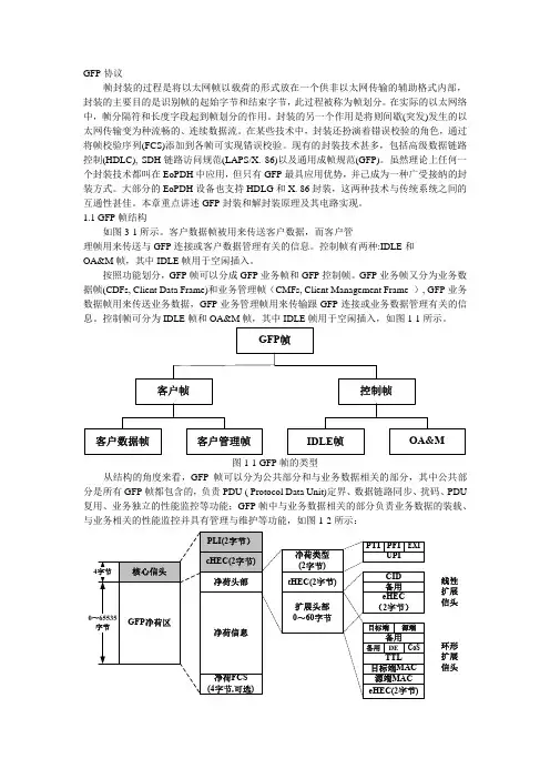
按照功能划分,GFP帧可以分成GFP业务帧和GFP控制帧。
GFP业务帧又分为业务数据帧(CDFs, Client Data Frame)和业务管理帧(CMFs, Client Management Frame ), GFP业务数据帧用来传送业务数据,GFP业务管理帧用来传输跟GFP连接或业务数据管理有关的信息。
控制帧可分为IDLE帧和OA&M帧,其中IDLE帧用于空闲插入,如图1-1所示。
图1-1 GFP帧的类型从结构的角度来看,GFP帧可以分为公共部分和与业务数据相关的部分,其中公共部分是所有GFP帧都包含的,负责PDU ( Protocol Data Unit)定界、数据链路同步、扰码、PDU 复用、业务独立的性能监控等功能;GFP帧中与业务数据相关的部分负责业务数据的装载、与业务相关的性能监控并具有管理与维护等功能,如图1-2所示:线性扩展信头环形扩展信头图1-2 GFP帧结构具体地讲,GFP的帧格式包括GFP核心信头和GFP负荷区。
![[整理后]GF产品手册](https://uimg.taocdn.com/fecadd39a8114431b90dd8ef.webp)

GF Piping Systems14M产品说明书0114 M产品目录1、 概述2、 注意事项3、 工作条件4、 电动执行器5、 阀体技术规格6、 执行机构接线图7、 执行机构调节8、 阀门装配9、 备件021、概述该手册主要介绍了执行器的安装、使用、维护及仓库保存,请仔细阅读以下说明。
危险性通知;用于警示操作者,可能出现的危害人身,及财产安全,操作者应该严格按照手册内容操作阀门。
2、注意事项本产品可以在室内或者室外使用;电动执行器属于非防爆产品,请注意避开易燃、易爆等环境;在长期有雨水或阳光直射的环境下,需要给电动执行器加装保护整个执行器的防护装置;注意执行器、阀门使用的环境温度;安装时需要考虑预留接线和维修的空间;在通电时,不能拆开驱动装置和阀门;在通电时,不能做配线工程;绝对禁止落下物品对产品造成的冲击,这会导致产品动作不良;绝对禁止踏上产品,这会引起驱动装置故障或人员摔落等事故;雨天或在有水花状态下,绝对禁止做配线工程;电动执行器不能开盖接线、换线,否则会对电动执行器密封性造成破坏。
3、工作条件工作介质:电力(交流&直流)电源接口:电缆线使用寿命:2万次 (寿命测试条件:额定负载15Nm,环境温度为25°C ,湿度为50%的工厂环境下 开关时间为15秒所测得,不同的负载和使用环境对测试结果会有不同的影响。
)※在同一控制触点下不可将两台或多台执行器并联使用0304型号EAM002NEAM002T电气参数额定电压220V AC 50/60HZ AC/DC 24V 220V AC 50/60HZ AC/DC 24V 工作电压范围AC190-250V DC22-28V AC95-265V/DC100-300V AC18-26V/DC22-32V功耗13.2W @运行0.0W @保持9.6W @运行0.25W @保持9.6W @运行0.12W @保持9.6W @运行0.85W @保持峰值电流@额定电压60mA @ 5ms450mA @ 5ms/ 500mA @ 5ms35mA @ 5ms @ AC230V350mA @ 5ms @DC24V保险丝规格1A2A1A2A电气接口7×0.2mm 电缆,耐压AC300V功能参数额定扭矩20N.m @额定电压回转角度90±2°最大回转角度360°手动操作配套六角扳手,在断电下使用运转时间约15秒约10秒位置指示机械指示器工作条件电气等级I 类(接地保护)III 类(安全低压)I 类(接地保护)III 类(安全低压)阻燃等级 1.6mmHB/UL94测试方法防护等级IP67绝缘电阻100M Ω/1500VDC 100M Ω/500VDC 100M Ω/1500VDC 100M Ω/500VDC 耐压等级1500V @ 1分钟500V @ 1分钟1500V @ 1分钟500V @ 1分钟环境温度-20°C~60°C 非工作温度≤ -40°C 或≥ 80°C 环境湿度5-95% RH 相对湿度,无结露冲击≤ 300m/S振动10~55HZ ,1.5mm 双振幅型号EAM006NEAM006T电气参数额定电压220V AC 50/60HZ AC/DC 24V 220V AC 50/60HZAC/DC 24V 工作电压范围AC190-250V AC/DC 22-28V AC190-250V AC/DC 22-28V 功耗55W @运行0.0W @保持50W @运行0.0W @保持55W @运行0.5W @保持50W @运行0.5W @保持峰值电流@额定电压0.3A @ 5ms2.5A @ 5ms0.3A @ 5ms2.5A @ 5ms保险丝规格2A10A2A10A电气接口端子接线排5A/600V 9 x (0.5-1.0) mm功能参数额定扭矩60N.m @额定电压回转角度90±2°最大回转角度90°/180°≤330°手动操作配套六角扳手,在断电下使用运转时间约15秒约10秒位置指示机械指示器工作条件电气等级I 类(接地保护)III 类(安全低压)I 类(接地保护)III 类(安全低压)阻燃等级 1.6mmHB/UL94测试方法防护等级IP67绝缘电阻100M Ω/1500VDC 100M Ω/500VDC 100M Ω/1500VDC 100M Ω/500VDC 耐压等级1500V @ 1分钟500V @ 1分钟1500V @ 1分钟500V @ 1分钟环境温度-20°C~60°C 非工作温度≤ -40°C 或≥ 80°C 环境湿度5-95% RH 相对湿度,无结露冲击≤ 300m/S振动10~55HZ ,1.5mm 双振幅(EAM006N & EAM006T )4、电动执行器a 、技术参数EAM002N & EAM002T05b 、尺寸图EAM002N & EAM002T型号EAM011NEAM011T电气参数额定电压220V AC 50/60HZ AC/DC 24V 220V AC 50/60HZAC/DC 24V 工作电压范围AC190-250V DC22-28V AC190-250V AC/DC22-28V 功耗80W @运行0.0W @保持70W @运行0.0W @保持80W @运行0.6W @保持70W @运行0.6W @保持峰值电流@额定电压0.7A @ 5ms3.5A @ 5ms0.5A @ 5ms3.5A @ 5ms保险丝规格2A10A2A10A电气接口端子接线排5A/600V 9 x (0.5-1.0) mm功能参数额定扭矩110N.m @额定电压回转角度90±2°最大回转角度90°/180°≤330°手动操作配套六角扳手,在断电下使用运转时间约15秒约10秒位置指示机械指示器工作条件电气等级I 类(接地保护)III 类(安全低压)I 类(接地保护)III 类(安全低压)阻燃等级 1.6mmHB/UL94测试方法防护等级IP67绝缘电阻100M Ω/1500VDC 100M Ω/500VDC 100M Ω/1500VDC 100M Ω/500VDC 耐压等级1500V @ 1分钟500V @ 1分钟1500V @ 1分钟500V @ 1分钟环境温度-20°C~60°C 非工作温度≤ -40°C 或≥ 80°C 环境湿度5-95% RH 相对湿度,无结露冲击≤ 300m/S振动10~55HZ ,1.5mm 双振幅EAM011N & EAM011T06c、主要部件序号部件材料1执行器本体耐热ABS 2阀位指示窗透明AS 3螺钉x43044手动轴3045手动轴油封NBR (丁腈)6LOGOPVC7六角扳手固定卡耐热ABS 8六角扳手工具钢9防水电缆接头NiLon (尼龙)10上下盖密封件NBR (丁腈)序号部件材料1执行器本体耐热ABS 2阀位指示窗透明AS 3螺钉x43044手动轴3045手动轴油封NBR (丁腈)6LOGOPVC7六角扳手固定卡耐热ABS 8六角扳手工具钢9防水电缆接头NiLon (尼龙)10上下盖密封件NBR (丁腈)11接线盒盖耐热ABSEAM006N & EAM006T & EAM011N & EAM011TDM mm DN mm d mm kv 100I/mm(△p=1 bar)Cv 100US gal./min(△p=1 psi)kv 100m /h(△p=1 bar)502631470103886521/2752200154132803903000210180100411065004553901255140115008056901506160166001162100020082253960027722380KV值B 、流量特性曲线和KV 值X 开度的(角度)%,Y 流量KV 或者CV 的%。

烽火MSTP设备以太网盘配置规范手册目录MSTP设备以太网盘的介绍 (3)一、GFC1机盘描述 (3)1.1主要功能描述 (3)1.2单盘说明 (3)1.3单盘配置 (5)1.4广播风暴抑制 (12)1.5静态单播地址 (12)1.6静态组播地址 (12)1.7二层流配置 (13)1.8单盘控制命令配置 (15)二、GFI1机盘描述 (16)1.1主要功能 (16)1.2 单盘基本功能 (16)1.3单盘配置说明 (17)三、ESC1机盘描述 (18)1.1主要功能 (18)1.2 单盘基本功能 (18)1.3单盘配置说明 (19)四、ESD1机盘描述 (21)1.1主要功能 (21)1.2单盘配置说明 (21)MSTP设备以太网盘应用要点 (23)一、开销字节的配置 (23)二、LCAS状态设置 (23)三、GFP封装设置及检查 (24)四、设备以太端口相关设置 (25)五、环回操作 (27)六、VLAN配置 (30)MSTP设备以太网盘的介绍一、GFC1机盘描述1.1主要功能描述●用于GF2488-01B/C系统设备的任一个高阶支路槽位和群路槽位。
对外提供8路FE以太网电接口(LAN口)和2个GE以太网光接口,对内提供8个FE全双工以太网数据接口(WAN口)和2个GE以太网光接口。
●每个支路由支路输入,输出接口电路,以太网二层交换电路、GFP/LAPS/HDLC封装和解封装电路,映射和去映射电路,STM-1信号的复接分接以及微机管理等几部分组成。
●二层交换功能增加了带宽限制,QOS等以前无法实现的功能。
●性能、告警屏蔽:通过网管命令,可设置某个告警或性能被屏蔽。
●完成POH开销处理,POH开销接入。
●下话指针处理,上话加入固定指针处理。
●开销监视:每个映射颗粒的开销均可监视,向网管上报高阶和低阶的告警和性能。
1.2单盘说明在GF2488-01B系统上,可以插在30~33,38~3D共10个槽位。

1、引言SDH/SONET作为一种传输技术,其优点是传输速率高,传输延时小,可组成自愈环网络,使网上传输的业务得到充分保护,在传输网上被大量采用,成为目前光纤网上的骨干传输设备。
但传统SDH/SONET设备是针对电路交换业务优化设计的,如果传输数据、图像等非对称性或即时业务,必然造成带宽的浪费。
同时,传统SDH/SONET传输设备只提供PDH、SDH/SONET 系列速率接口,IP业务和图像业务必须经PDH、SDH/SONET接口,进入SDH/SONET传输通道,转换电路层次多,设备造价高。
以传输电路交换业务为主的SDH/SONET光传输网络已不能适应多业务共存的传输要求。
近几年,正当SDH/SONET传输技术已过时的谣言被过分渲染时,世界上许多通信厂商却在利用各种传送载体作为SDH/SONET的下层结构进行研究和试验,而且已经在操作、维护及网络收入等方面积累了许多有价值的经验。
新一代SDH/SONET技术主要体现在拥有本地以太网交换和处理功能的ADM、GFP在SDH/SONET中的应用及GMPLS-SDH技术等。
2、新一代SDH/SONET ADMs发展趋势传统的ADM仅仅为处理一种速率的信号作了优化,如STM-1、STM-4、STM-16或STM-64,并且只支持数量有限的业务接口。
但是每种速率都需要自己的ADM、单独的DXC互联它们。
这样不仅成本高昂,而且建网时间长和管理不便。
此外,由于传统的ADM网络包含大量的网络设备,管理员必须花费较长的时间和较多的资源来配置电路。
例如,拥有STM-16 ADM的服务提供商在其每个设备的放置点都需要相应的支路板互连那些提供穿过全网的连接及配置设备间的电路。
因此,传统的ADM已经无法满足日渐增长的数据传输需求。
近几年,面对数据业务的发展,SDH/SONET ADMs技术为应对新业务的出现在不断地向前发展。
第一代SDH/SONET ADMs由汇集各种低速率接口输入到高速OC-N信号单一过程的复用器/解复用器组成。
绿色荧光蛋白(GFP)基因的克隆和表达背景知识绿色荧光蛋白( green fluorescent protein , GFP)是一类存在于包括水母、水螅和珊瑚等腔肠动物体内的生物发光蛋白。
当受到紫外或蓝光激发时, GFP 发射绿色荧光。
它产生荧光无需底物或辅因子。
发色团是其蛋白质一级序列固有的。
GFP 由 3 个外显子组成,长 2.6kb ;GFP 是由 238 个氨基酸所组成的单体蛋白 ,相对分子质量为27. 0kMr ,其蛋白性质十分稳定,能耐受 60℃处理。
1996 年 GFP 的晶体结构被解出,蛋白质中央是一个圆柱形水桶样结构,长 420 nm,宽 240 nm,由 11 个围绕中心α螺旋的反平行β 折叠组成,荧光基团的形成就是从这个螺旋开始的,桶的顶部由3 个短的垂直片段覆盖,底部由一个短的垂直片段覆盖,对荧光活性很重要的生色团则位于大空腔内。
发色团是由其蛋白质内部第 65-67 位的 Ser-Tyr-Gly 自身环化和氧化形成 .实验一质粒DNA 的分离与纯化一、实验目的掌握一种最常用的质粒 DNA 提取方法:碱裂解法。
该法用于从小量培养物中抽提质粒 DNA ,比较方便、省时,提取的质粒 DNA 质量较高,可用于 DNA 的酶切、 PCR 甚至测序。
二、基本原理质粒是一类在细菌细胞内发现的独立于染色体外,能够自主复制的稳定的遗传单位。
迄今为止,从细菌中分离得到的质粒都是环型双链 DNA 分子,分子量范围从 1kb 到200kb 。
质粒 DNA 可持续稳定地处于染色体外的游离状态,但在一定条件下又会可逆地整合到寄主染色体上,随着染色体的复制而复制,并通过细胞分裂传递到后代。
在大多数情况下质粒 DNA 复制中的酶体系和细菌染色体复制10-200 个拷贝。
当宿主细胞的蛋白时所用的酶是相同的。
有些质粒复制受宿主细胞复制作用的严格限制,因此每个细胞中只含一个或几个拷贝,称为严谨型质粒,有的质粒的复制受宿主细胞的控制不严,称为松弛型质粒,它们在每个细胞中的数目可达质合成受到抑制时(例如经氯霉素处理),细菌染色体虽不再增加,但松弛型质粒 DNA 可继续被复制,以至每个细胞内的拷贝数可以增至一千到几千。
Maintenance• For dust and dirt, wipe Rollator gently with damp, soft cloth.• Inspect wheels periodically for wear or damage. Use a mild soap and water solution to clean, rinse with clear water, then dry with a soft cloth.• Never use organic solvents, abrasive cleaners, or scouring pads on any part of the rollator. • Verify operation of the brakes and have them adjusted if necessary by your GF Health Products, Inc. authorized distributor.• Inspect Rollator weekly for proper function and wear. If any component is not in proper working order or appears worn, contact your GF Health Products, Inc. distributor for repair and/or appropriate replacement parts.• If handgrip or hand brake are loose, DO NOT use. Contact your GF Health Products, Inc.authorized distributor.• Replace any broken, damaged or worn items immediately.• For the best service from your rollator, always use replacement parts from GF Health Products, Inc.• Periodically inspect the casters and caster stems for assembly tightness and verify that the wheels are free of hair or other debris that could interfere with free wheel operation. 1. Each individual should ALWAYS consult with their physicianor other health care professional to determine properadjustment and usage.2. The brakes MUST be in the locked position before using theseat.3. All wheels MUST be in contact with the floor at all timesduring use. This will ensure the rollator is properly balanced.4. This product has a maximum user weight limitation of 500 lbsEVENLY DISTRIBUTED.ALWAYS observe the user weight limitation on the manual.5. Ensure handgrips DO NOT twist on rollator handle -otherwise damage or injury may occur.6. After installation and before use, ensure that all attachinghardware is securely tightened.7. ALWAYS use caution when using the rollator on wet andslippery surfaces. DO NOT use the rollator on stairs, steepinclines or uneven terrain.8. DO NOT hang anything from the frame of the rollator. Itemsshould be placed in the basket.9. The basket has a weight limitation of 10 lbs (5 kg). Itemsplaced in the basket should not protrude out from the basket.10. Before attempting to reach objects or pick them up from thefloor by reaching down between your knees, place feetsecurely on the floor. Use EXTREME caution when reaching for any object.11. GF Health Products, Inc. assumes no responsibility for anydamage or injury caused by improper installation, assembly or use of this product.12. Inspect rollator weekly or on a set routine preventativemaintenance schedule for normal wear and tear. If anycomponent is not in proper working order or appears worn, contact your Lumex dealer for repair and/or appropriatereplacement parts.13. If the hand brakes fail to stop the Rollator, contact your GFHealth Products, Inc. authorized distributor immediately for adjustment or replacement.Safety Guidelines –Please Read Before UseInstructions for Use –Please Read All Instructions Before Use. Please consult a healthcare professional for the proper adjustment.Opening the Rollator1. Remove Rollator and other components from carton.2. Unfold frame; spread front and back legs apart.3. Push down locking mechanism to secure legs in place.NOTE: Ensure the side crossbars (locking mechanism)lock down.Folding the Rollator1. If necessary, remove the accessories and lift the seat.2. Pull up on the locking mechanism underneath the seat.Using the Hand BrakeBrakes should be used in one of the following method:• To Remain Stationary: Hold the hand brake up.• To Continue Mobility: Release the brake. To unlock, pull up on the top portion of the brake handle.• To Sit on Seat: Push down on the bottom portion of the brake handle to lock.• To unlock, pull up on the top portion of the brake handle. Note: Always lock hand brakes when user is immobile; never sit on rest seat if hand brakes are not locked.Adjusting the Height1. Remove the adjustment knob and bolt by turning counterclockwise.2. Consult with healthcare professional for proper adjustment.3. Install the adjustment knob into one of the adjustment holes by turning clockwise.4. Repeat STEPS 1– 3 for the other side.Make sure that the height adjustment is at the same height for both handles to ensure safety and proper use.NOTE: After adjusting the height, the brakes of the rollator must be checked and, if necessary, adjusted.Attaching BasketBasketInstall the basket underneath the seat. On some rollator models, thebasket is designed to fit underneath the seat or in the front bypositioning the hooks on the front seat support frame.Rodador de 4 Ruedas de LujoItem RJ4200ADeluxe4-Wheel RollatorWARNING: Indicates a potential hazard situation or unsafe practice that, if notavoided, could result in death or serious personal injury.CAUTION: Indicates a potential hazard or unsafe practice that, if not avoided, couldresult in personal injury or product/property damage.NOTE: Provides application recommendations or other useful information to ensurethat you receive the greatest benefit from this product.Features• Improves mobility and allows for greater independence forthe user on the go• Heavy duty steel frame• Ergonomic hand grips and hand brakes allow user tooperate with ease• Complete with basket for storage of personal items• 500 lb maximum weight capacity – EVENLY DISTRIBUTEDWARNINGWARNING: DO NOT use this product without first completelyreading and understanding these instructions and any additionalinstructional material supplied with this product. If you areunable to understand the warnings, cautions or instructions,contact a healthcare professional, dealer or technical personnelbefore attempting to use this equipment - otherwise, injury ordamage may occur.WARNING: DO NOT use the rollator if there is any damage to theframe.WARNING: DO NOT use the rollator as a wheelchair or transportdevice. Rollators are not intended to be propelled while seated.WARNING: If components are damaged or missing, contact yourdistributor immediately. DO NOT substitute parts.WARNING: Before use, ensure that all assembled parts aresecure and all hardware is tightened.WARNING: Care should be taken to ensure that all hand andheight adjustments are secure, and that wheels and movingobjects are in good working order before using this rollator.WARNING: When using the rollator in a stationary position, thehand brakes MUST be locked.WARNING: ALWAYS observe the user weight limitation.WARNING: Notice for California Customers-California Proposition 65 WARNING: This product contains achemical known to the State of California to cause cancer andreproductive or developmental harm.WARNING: DO NOT attempt to reach objects if you have tomove forward in the seat. Reaching for these objects will causea change to the weight distribution of the rollator and may causethe rollator to tip, resulting in injury or damage.DetachableWire BasketHandgripLockingHand Brake8" WheelRest SeatDetachable ClearPlastic Food TrayHandle Bar(ChromeTube Section)AdjustmentKnobRear LegBlack LockingMechanism。
Technical Reference Section: pH/ORPInformation in this section addresses frequently asked questions regarding pHCommon Acids1M HCl: 0.0 pHSulfuric Acid: 0.3 pHLemon Juice: 2.0 pHVinegar: 3.0 pHWine: 3.5 pHBeer: 4.5 pHMilk: 6.0 pHCommon BasesEgg Whites: 7.5 pHSeawater: 8.0 pHSodium Bicarbonate: 8.4 pHAmmonia: 11.6 pHPhoto Developer: 12.0 pH0.1M NaOH: 13.0 pHLye: 14.0 pHTechnical Reference Section: pH/ORPPrinciple of Operation• Standard pH/ORP electrodesare also commonly called combination electrodes; a pH/ORP measuring electrode and a reference measuring electrode are combined in a single body. The pH/ORP sensor measures the amount of hydrogen ions in the liquid. The pH signal is measured against the steady reference signal. Various chemical elements leaching through the porous reference junction can react with the reference electrolyte, dilute the electrolyte solution, or attack the silver chloride element; in either case, it will disturb the steady reference signal. Stray electrical currents will also affect the steady reference signal. A temperature element is also built into the pH/ORP combination electrode. Instruments interpret and temperature compensate the pH/ORP and reference signals into pH/ORP readings at 25°C (77°F). Signet offers three different groups of Standard pH/ORP Electrode Models: Models 2714-2717, 2754-2757, and 2774-2777• Differential pH/ORP electrodesfunction similar to the standard (combination) electrodes, but the reference design is modified and there is a third electrode, the solution ground. The pH and reference electrodes are measured against the solution ground. The solution ground drains stray currents away from the reference element, hence maintaining a steady signal at all times. The reference salt bridge slows or stops various chemical elements from leaching into the reference chamber . Chemicals that leach in may dilute the electrolyte but will not react with the glass-encased reference silver chloride element. The reference electrolyte can be refreshed if it is diluted or depleted. The temperature element is embedded in the pH/ORP electrode for an extremely quick response.Signet offers one group of DifferentialpH/ORP Electrodes: Models 2764 - 2767Cutaway of 2776 pH electrodeCutaway of 2766 pH electrodereference salt bridge3 (front chamber)temperature elementSignet offers what is called combination pH/ORP electrodes; a combination of three or four electrodes built into one common body that measures the pH or ORP of the solutions. These electrodes are the pH/ORP sensing element, temperature sensing element (pH only), the reference, and sometimes a solu-tion ground. An electrical path between the process solution, reference elec-trode, and the pH/ORP sensing electrode must always be present to complete the measuring circuit. When the circuit is broken or interrupted, the result is a faulty reading. There are only a few things in a chemical process that would high temperatures, and particles that can break the glass. On the other hand, there are many problems that can occur with the reference electrode. The reference silver chloride sensing element (wire) is exposed to the process liquid via the primary porous reference junction, which is in con-cals in the process. Many application liquids do not chemically react with the and therefore, a differential style electrode should be used. There are three advantages of the differential electrode:Standard versus Differential pH/ORP Electrodes:Technical Reference Section: pH/ORP A general rule of thumb is to use a differential electrode if you have mercury, copper, lead, chlorate, bromine, iodine, cyanide, or sulfide compounds in the differential electrodes.1. If the process chemicals attack the KCl electrolyte, the reference electrolyte chamber is refillable.2. If the reference junction becomes clogged by chemical reactions between the KCl and the process chemicals, the reference salt bridge is replaceable. 3. If there are stray currents or if there are process chemicals that attack the silver chloride wire in the standard electrodes, it will not attack it in the differential electrode because the wire is encased in a glass electrode.Technical Reference Section: pH/ORP• It is important that the sensing end of pH and ORP electrodes remain wet, for they may be permanently damaged if allowed to dehydrate. This is true for both in-line and submersible installation configurations. However, be careful to keep the electrical interconnection between electrode and preamplifier dry and clean at all times. Moisture in this area can also cause permanent damage.• pH control is best when performed in a tank. This is especially true in neutralization applications since it is very important for reagents to mix thoroughly with waste fluids, and to be allowed adequate time for the reactions to occur. Limiting adjustments to fewer than 3 pH units per stage, and sizing tanks to provide at least 10 minutes retention time, will increase the probability of producing safe effluents.• For bulb-style pH and ORP electrodes, significant natural self-cleaning by turbulent eddies is achieved at velocities of 1.5m/s or more (5 ft/s). Flat surface electrodes get adequate self-cleaning at velocities of 0.3 to 0.6m/s (1 to 2 ft/s). In all cases, exposure to velocities greater than 3m/s (10 ft/s) can cause excessive measurement noise and electrode wear and should be avoided.• The aging of pH and ORP electrodes (i.e., reference depletion and decreased glass sensitivity) results from a series of chemical reactions. And as a general rule, the rates of chemical reactions double with every increase of 10°C (50°F). This means shorter life expectancy for all pH and ORP electrodes as application temperatures increase.Important Application Tips• HF acid and strong caustics etch pH glass. High concentrations, especially at high temperatures, destroy electrodes quickly. For applications containing trace quantities of HF (<2%), use the Signet 3-2714-HF or 3-2754-HF electrode. This electrode has a polymeric constituent in the pH glass that resists attack by HF and extends the service life considerably over “normal” electrodes.• In applications where process temperatures will drop below 10°C (50°F), use the bulb-style electrodes in place of the Flat style electrode. This is a function of the electrical impedance of the glass that increases dramatically as temperature decreases. • Proper electrode placement within a tank is also very important. Electrodes should be mounted in well-mixed areas, away from reagent and waste introduction. It is usually advisable to position the electrode near the discharge outlet of the tank.• In-line pH control is not recommended because it is very difficult to determine the amounts of reagent necessary to achieve a desired reaction if both pH and flow are variables. However, in-line pH monitoring is very commonand useful.• Cleaning pH and ORP electrodes and calibrating the systems should be done regularly. The required frequency is application-dependent, but once/week for cleaning, and twice/month for calibration is recommended.• Isopropyl alcohol may be used for removing mild grease and oils from the pH sensitive glass or from the metallic tips of ORP electrodes. Use 5% HCl on porous reference junctions clogged with hard water deposits, or other solvents/detergents as necessary. Always consider the electrode’s materials of construction when selecting a cleanser . Technical Reference Section: pH/ORP ORP Values of Standard pH Buffers Saturated with Quinhydrone • The purpose of calibration is to compensate the system for the deplete and must be replaced. A good time to determine the condition of an electrode is after cleaning and during calibration. Note the mV readings in pH values: pH 7 = 0 mV, pH 4 = +177 mV, pH 10 = -177 mV. Replace output differs more than 50 mV table below: Maintenance Tips • 12 months at 25°C (77°F). • Refrigeration will extend this period, but do not allow them to freeze! Expansion of internal solutions during freezing can cause permanent damage to the electrodes. • The risk of putting older electrodes into service is the possible electrodes are marked with date codes to identify the date of manufacture.pH4pH7Temperature (°C)202530202530ORP Value (mV)268264258928779Technical Reference Section: Conductivity/Resistivity Conductivity is a measure of the abil-ity of a material to convey an electric current. The proper term for this ability of a solution is electrolytic conductivity, since only ions conduct electric current in solution. When dissolved in solution, many substanc-es such as salts, acids and bases dissociate into ions. Electrolytic conductivity (or simply conductivity) is therefore an indirect measure of the ionic concentration of a solution. Generally, conductivity increases and decreases with the concentration of ions.Unlike pH, which is a specific mea-sure of Hydrogen ion concentration, conductivity is a non-selective mea-surement of all the dissolved ionic species in a solution. As such, it is a highly utilized parameter in water, wastewater and industrial process analyses. For example, conductiv-ity is used to monitor the salt load of waters entering treatment facilities, to monitor and control the quality of drinking water and ultra-pure water, and to otherwise detect contaminants in industrial processes.According to the International Stan-dards Organization (ISO) the unit of conductance is the Siemens (S), after Werner von Siemens (1816-1892). However, the following three separate units of measure are commonly used to express conductivity: Siemens/cm (S/cm), mhos/cm, and μS/cm. Forany given measurement Siemens/cm and mhos/cm are exactly equal;1 µS 1 M Ω10 µS 100 K Ω1,000 µS 10,000 µS 50,000 µS 200,000 µS 100 µS 10 K Ω400,000 µS 100,000 µS 0.055 µS 18.2 M ΩCooling Tower Deionization Regen. Chemicals PPM TDS 5505005,00025,00050,000100,000200,000Information in this section addresses frequently asked questions regarding Conductivity (Resistivity) and is provided as REFERENCE ONLY to supplement procedures and recommendations specifically outlined in individual product instruction manuals. All manuals, data sheets, and additional helpful information are available at .they are merely different labels for the same value. The denominator in these units (cm) is sometimes trun-cated but is always assumed to be present. Ohm•cm is a unit of resistivity (the inverse of conductivity) and is fre-quently replaced by “Ω” the symbol for electrical resistance. Units of resistivity are most commonly associ-ated with ultra-pure water measure-ments in the millions of ohm•cm, or M Ω (megohms).Some users will also find it desir-able to express conductivity in terms of parts per million (PPM) or parts per billion (PPB) of total dissolved solids (TDS). Signet instruments accommodate this by allowing the entry of a TDS factor to convert from standard units of conductivity. (See the instruction manual of any current Signet conductivity instrument for details.)Conductivity is a measurement parameter with a very wide range. For example, ultra-pure water has a theoretical maximum resistivity of ap-proximately 18.2 M Ω, approximately 0.055 μS (microsiemens), whereas concentrated acids and bases can exceed 400,000 μS. Despite the wide-ranging possibilities most applica-tions for conductivity measurement are much narrower . Tap water, for instance, typically measures between 50 and 1,000 μS.Definition of Conductivity and Resistivity。