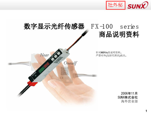
神视光纤传感器介绍FX-301,FX-411
- 格式:ppt
- 大小:1.76 MB
- 文档页数:15


DescriptionThe EXS301 Series strobe signaling appliances are in-tended for general utility signaling use. The strobes areUL and cUL listed for use in Class I, Division 1, Group C and D, Class I, Division 2, Group A, B, C and D, Class II,Division 1, Group E, F and G, Class II, Division 2, Group F and G, and Class III Division 1 and 2 hazardous locations with operating temperature codes per Table 2.The strobes are UL and cUL Listed, as Type 3R and 4X en-closures. Additionally, the 120V AC strobes are UL and cUL listed as Marine enclosures.The strobe flashes a 360-degree beam of light approxi-mately 65 times per minute.The 120V 50/60 Hz strobes are available in pendant, bracket,ceiling, or stanchion mount models (Figure 1).Installationb.Ceiling Mount Models (Figure 3): Mount thecatalog number EV22, ceiling/wall mounting module, using appropriate hardware (not supplied) suitable for the mounting surface.Proceed to step 2.c.Wall Mount Models (Figure 4): Install the catalog number EV22 ceiling/wall mounting module using appropriate hardware (not supplied) for the mounting surface. Install the catalog number EV87 wall mounting elbow to the wall box. Run the unit's wiring through the elbow to the wall box. Proceed to step 2.d.Stanchion Mount Models (Figure 5): Install thecatalog number EVMJ4, stanchion mounting module, to the main housing. Run the unit's wires through the 1 1/4" conduit to the appropriate junction box. Install the unit on the conduit.Proceed to step 2.2.Connect field earth ground wire to ground screw orearth ground via conduit system.ing wire nuts, connect the incoming (+) or whitewire to the unit's two (+) white wires and the incoming (-) or black wire to the unit's two (-) black wires. See Table 2 for required supply wire temperature ratings.4.As appropriate, install the fixture on the mountingmodule.Install this unit in accordance with the applicable require-ments in the latest edition of the National Electrical Code and Canadian Electrical Code.1.Mount using the following applicable method.a.Pendant Mount Models (Figure 2): Install thecatalog number EXVMP3, pendant mounting module, to the main housing. Install explosion-proof hanger box (not supplied). Secure 3/4"(19 mm) NPT threaded conduit (not supplied) to the box. Install the unit on the conduit. Proceed to step 2.5.Apply power to the unit and ensure proper function.Figure 1. Mounting OptionsHazard-Gard TMStrobe Light EXS301 SeriesInstallation & Maintenance InformationIF 1486Figure 2. Detail of Pendant Mounting Figure 3. Detail of Ceiling MountingMaintenanceDisassemble the unit as follows (Figure 6):counterclockwise direction. Remove the ring and globe assembly.3.Refer to Table 1 for the correct replacement catalognumber and replace the necessary part.4.To replace, simply screw the unit on until it seats firmlyonto its gasket. Tighten the unit another 1/8 to 1/4turn. Tighten the setscrew.5.Reinstall the guard, where applicable, and secure usingthe three supplied screws.6.After the unit is assembled, apply power and makesure the unit functions properly.1.Loosen the (3) guard screws and remove the guard.2.Loosen the globe and ring assembly set screw. Inserta suitable tool into the notches in the globe and ring assembly and loosen the assembly by prying in aTable 1. EXS301 Hazard-GardCatalog Electrical Conduit Flash Description Number Ratings Size Rate Housing LessEXS301***/120120V 50/60 HzN/A Approx.Mounting Module 0.10A 65 fpm Ceiling/WallEV22N/A3/4" NPT N/A Mounting Module PendantEVMP3N/A 3/4" NPT N/A Mounting Module StanchionEVMJ4N/A 1 1/4" NPTN/A Mounting Module Wall Bracket EV87N/AN/AN/AMounting Elbow*Letter in this position denotes color of the globe: A - amber, B - blue, C - clear, G - green, R - red or M - magentaTable 2. RatingsOperating TemperatureAmbient Supply Wire Class I, Div. 2Class I, Div. 1 & 2Class II & III, Div. 1Class II & III, Div. 2Temp.Temp. MarkingGroups A, B Groups C, D Groups E, F , GGroup G40°C 75°C T4 (135°C)T6 (85°C)T4A (120°C)T4A (120°C)55°C 90°C T3C (160°C)T6 (85°C)T4 (135°C)T4 (135°C)65°C105°CT3C (160°C)T6 (85°C)T4 (135°C)T4 (135°C)All statements, technical information and recommendations contained herein are based on information and tests we believe to be reliable. The accuracy or completeness thereof are not guaranteed. In accordance with Crouse-Hinds “T erms and Conditions of Sale”,and since conditions of use are outside our control, the purchaser should determine the suitability of the product for his intended use and assumes all risk and liability whatsoever in connection therewith.IF 1486Revision 1New 11/04Cooper Industries Inc.Crouse-Hinds DivisionPO Box 4999, Syracuse, New York 13221 • U.S.A.P/N 3100906 (IF 1486) OFFSET SPEC INSTALLATION INSTRUCTIONS FOR CROUSE-HINDS CATALOG SERIES EXS301 HAZARD-GARD FOR USE IN HAZARDOUS LOCATIONS(1) 11" X 17" SHEET PRINTED BOTH SIDES. FOLD THREE TIMES TO DIMENSIONS SHOWN ON DETAIL WITH PART NUMBER ON THE OUTSIDE.MATERIAL: STANDARD WHITE OFFSET STOCK CHARACTERS: TO BE BLACK ON WHITE BACK-GROUND NOTE: MECHANICALS HAVE ALREADY BEEN REDUCED TO ACTUAL SIZE. FOLD DETAIL REFERENCE ONLYIssue:01File:3100906Approved by:KRT。

301云台解码器使用说明书(中文版第一版)一技术参数工作电压:AC 24V± 10% 50HZ/60H乙工作电流:输入交流1850MA(含云台电流)。
环境温度:全天候、-30 °C — + 70 C、相对湿度90%RH 。
镜头电压:DC 12V和DC6V电流200MADC6V/DC12V 通过板上跳线帽选择。
镜头控制:光圈、聚焦、变倍。
云台电压:AC 24V/1000MA云台控制:上、下、左、右、自动(左上、左下、右上、右下)。
摄像机电源:DC 12V/500MA通信接口:标准RS-485;自带120欧终端电阻。
支持协议:多种常用协议,可为用户定制协议。
地址数量:64个地址,可扩充(加设备)。
板尺寸:80X90 (mr)二系统概述:1•解码器是与监控系统配套使用的一种前端控制设备,可控制球机、室内外交流24V云台、电动三可变(电压为6V或12V)镜头;提供摄像机电源等。
2•使用通用的RS- 485通讯接口;兼容多种常用的控制协议;自带120欧匹配电阻。
3•可提供稳定的12V直流电源(500MA供摄像机及红外灯使用。
4•具有超强的防雷、抗死机性能,性价比极高,适用于各款数字硬盘录像系统、矩阵系统、键盘、PC控制等设备。
三.云台:1 •可控制云台的种类:可控制全球和半球的内置式云台、普通型云台、以及其它特殊型号的云台和室内外全方位云台的上、下、左、右和自动运行,支持左上、左下、右上、右下;室内外水平云台的左、右和自动运行。
2.云台电压:本机支持24 V的交流云台,不支持“ AC220V的云台。
3•云台的保险措施:本机使用自恢复保险丝,如云台接错线(即云台控制线的公共线接到其它的接口上如自动、上、下、左、右),云台工作时自恢复保险丝就会自动关断电路,保护云台不致烧毁。
本系统有完善的保险措施,共使用六个自恢复保险丝:RS-485通讯接口保险丝250V/120MA二个、系统总保险丝(含云台供电保险)1850MA —个、摄像机电源保险丝750MA一个、系统控制部分保险丝300M1个、镜头保险丝200M1个。
178SC 系列传感器-PLC 连接系统使用MIL 连接器一次最多可连接16个I/O 设备在主单元上无需使用任何工具最多可并排连接16个光纤传感器,如FX-301/305/311/411/412系列。
同时,使用分立单元可进行分散安装。
此外,使用连接器输入/输出扩展单元、光电传感器、微型光电传感器、接近传感器、压力传感器或其他类型的传感器可以很方便地连接至输出设备上。
SC 179订购指南配件(另售)标记封条·SC-MA1连接器底帽·SC-PK 注:请使用松下电工的MIL连接器所附电缆进行设备连接。
以20芯连接器与16信道单元的方式进行连接。
详情请与生产商直接联系。
双端MIL连接器随附电缆(20芯)松下电工AY15840等PC继电器端子/PC端子附加安装电缆一端MIL连接器随附电缆(20芯)松下电工AY15853等继电器多芯压接接头电缆与松下电工MIL连接器继电器端子针排列一致。
详情请与生产商直接联系。
SC180规格注:1) 插件型传感器主单元SC-MIL 除MIL 连接器外还装备有电缆引线连接器,可以接受来自不同电源的电压。
2) 与所有单元连接至SC-MIL 时允许的最大消耗电流一样。
电源单元允许的电流量或连接电缆允许的电流量为2A 以下时,请将电流调节至最小值。
无线连接器适用单元注: 串联连接的FX-301/305/311/411/412系列,电源电压应为12~24V DC ±10%脉动P-P10%以下。
无线连接器注: 详情请参见P .102~的FX-301系列,P .138~的FX-311系列,P .168~的FX-301(P)-F 和P .184~的FX-CH(-P)。
SC181规格4) 不论连接的I/O 单元的数量,都占用8信道信号。
5) 不能连接直流双线式传感器和开关等。
6) 将输入/输出线路通过的最大电流设定至50mA 以下。
注:1) 由SC-MIL 电源电压决定。
和其光电——————————————————————FOT-301系列荧光光纤测温仪产品说明书西安和其光电科技有限公司 地址:西安市高新区新型工业园西部大道60号联系人:张文松(先生) 139****1347E-mail:*******************.cn——————————————————————一、测温仪组件FOT-301荧光光纤测温仪共由主机、电源适配器、电源线和通信电缆、光纤探头等部分组成。
1、主机:测温仪主体部分,负责温度的采集和上位机的通信。
和——————————————————————2、电源适配器:为电源主体提供工作电压。
3、电源线:将市电AC220V送入电源适配器。
和其光电——————————————————————4、通信电缆:将测温主机测得数据输送至电脑串口。
5、光纤探头⑥为HP光纤接头⑦为光纤测温探头二、测量原理荧光光纤温度传感器是基于稀土荧光物质的材料特性实现的,当某些稀土荧光物质受紫外线照射并激发后,在可见光谱中发射线状光谱,即荧光及其余辉(余辉为激励停止后的发光)。
荧光余辉的衰变时间常数是温度的单值函数,通常温度越高,时间常数越小。
只要测得时间常数的值,就可以求出温度。
应用这种方法测温的最大优点,就是被测温度只取决于荧光材料的时间常数,而与系统的其他变量无关,例如光源强度的变化、传输效率、耦合程度的变化等都不影响测量结果,较其它测温法原理上有明显优势。
和和其光电——————————————————————三、测量方法1、将电源线接好;2、将HP光纤接头⑥插入HP光纤接口⑤;3、将光纤测温探头⑦放到被测物体表面(接触);4、开启电源开关;5、液晶显示屏显示待机,经过数秒后,显示测试温度,温度测试开始。
四、技术指标型号 FOT-301测温范围 -40~+150℃分辨率 0.1℃测量精度 ±0.5电源 ~220V五、测温仪特点抗电磁干扰高压绝缘精度及灵敏度高耐高压防腐蚀和其光电——————————————————————可远程监测 长寿命能在恶劣的环境下工作,适应性好六、 应用荧光光纤温度传感器及测量系统,具有抗电磁干扰、高压绝缘、稳定可靠、高精度、高灵敏度、微小尺寸、长寿命及耐腐蚀、适应性好等特点,既可以采用接触式的测量方式,也可以采用非接触式的测量方式,非常适合应用于电力、医疗、石油化工、工业微波、食品安全、科学研究和航空航天军事国防等领域的温度实时监测与控制。