DuroProx电感式传感器
- 格式:pdf
- 大小:104.72 KB
- 文档页数:1
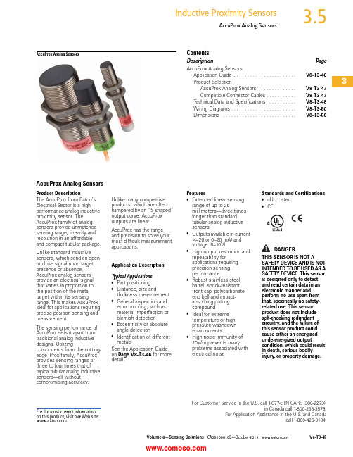
Volume 8—Sensing Solutions CA08100010E—October V8-T3-453For Customer Service in the U.S. call 1-877-ETN CARE (386-2273),in Canada call 1-800-268-3578.For Application Assistance in the U.S. and Canadacall 1-800-426-9184.AccuProx Analog SensorsAccuProx Analog SensorsContentsDescriptionPage AccuProx Analog SensorsApplication Guide . . . . . . . . . . . . . . . . . . . . . . .V8-T3-46Product SelectionAccuProx Analog Sensors . . . . . . . . . . . . . .V8-T3-47Compatible Connector Cables . . . . . . . . . . .V8-T3-47Technical Data and Specifications . . . . . . . . . .V8-T3-48Wiring Diagrams . . . . . . . . . . . . . . . . . . . . . . . .V8-T3-50Dimensions . . . . . . . . . . . . . . . . . . . . . . . . . . .V8-T3-50AccuProx Analog SensorsProduct DescriptionThe AccuProx from Eaton’s Electrical Sector is a high performance analog inductive proximity sensor. The AccuProx family of analog sensors provide unmatched sensing range, linearity and resolution in an affordable and compact tubular package.Unlike standard inductive sensors, which send an open or close signal upon target presence or absence, AccuProx analog sensors provide an electrical signal that varies in proportion to the position of the metal target within its sensing range. This makes AccuProx ideal for applications requiring precise position sensing and measurement.The sensing performance of AccuProx sets it apart from traditional analog inductive designs. Utilizingcomponents from the cutting-edge iProx family, AccuProx provides sensing ranges of three to four times that of typical tubular analog inductive sensors—all without compromising accuracy.Unlike many competitive products, which are often hampered by an “S-shaped” output curve, AccuProx outputs are linear.AccuProx has the range and precision to solve your most difficult measurement applications.Application DescriptionTypical Applications ●Part positioning ●Distance, size andthickness measurement ●General inspection and error proofing, such as material imperfection or blemish detection ●Eccentricity or absolute angle detection ●Identification of different metalsSee the Application Guide on Page V8-T3-46 for more detail.Features●Extended linear sensing range of up to 25millimeters—three times longer than standard tubular analog inductive sensors●Outputs available in current (4–20 or 0–20 mA) and voltage (0–10V)●High output resolution and repeatability forapplications requiring precision sensing performance●Robust stainless steel barrel, shock-resistant front cap, polycarbonate end bell and impact-absorbing potting compound●Ideal for extreme temperature or high pressure washdown environments●High noise immunity of 20V/m prevents many problems associated with electrical noiseStandards and Certifications●cUL Listed ●CEDANGERTHIS SENSOR IS NOT ASAFETY DEVICE AND IS NOT INTENDED TO BE USED AS A SAFETY DEVICE. This sensor is designed only to detect and read certain data in an electronic manner and perform no use apart from that, specifically no safety-related use. This sensor product does not include self-checking redundant circuitry, and the failure of this sensor product could cause either an energized or de-energized outputcondition, which could result in death, serious bodily injury, or property damage.For the most current information on this product, visit our Web site:3Application GuidePresenting AccuProx—Unmatched Analog Rangein a Proven PackageHistorically, analog sensorshave been limited by veryshort sensing ranges—aslittle as one or twomillimeters. By utilizingtechnology first perfected inthe iProx family of digitalinductive sensors, AccuProxcan sense objects as far as25millimeters. This extendedrange can be achievedwithout making compromisesoften found in competitiveproducts, such as reducedoutput accuracy.AccuProx utilizes many ofthe proven materials foundin other tubular sensorfamilies. The threaded barreland included mounting nutsare made of stainless steel,which exhibits superiorcorrosion and abrasionresistance versus nickel-plated brass. AccuProx alsofeatures a proprietary internalpotting compound thatabsorbs impacts and vibrationwhile sealing out moisture.The materials used in theconstruction of AccuProx aretime-tested and proven towork.High Output AccuracyAnalog inductive sensors areoften used in applicationsthat require a higher level ofprecision than a standarddigital sensor. For example,applications such as partinspection require a sensorthat can detect very smallvariances. AccuProx has beendesigned with theseapplications in mind.Output accuracy isdetermined by the repeataccuracy, linearity, resolutionand response time of thesensor.Repeat accuracy refers to thevariations in sensing distancebetween successive sensoroperations due to componenttolerances, where alloperating conditions are keptthe same. The repeataccuracy of an 18 millimeter,unshielded AccuProx sensoris less than 20 micrometers.See the chart below for arepeat accuracy comparisonof AccuProx versus thecompetition.Linearity refers to the shape ofthe output curve. Manycompetitive analog sensorsexhibit a wavy or “S-shaped”output curve. This means thata change in target distancemay not always translate intoan equivalent change inoutput, particularly at theinnermost and outermostranges of a non-linear analogsensor. AccuProx features alinear output. See thediagram below for anexample of AccuProxversus a non-linearcompetitive offering.Resolution refers to thenumber of “steps” in thesensor output. A higherresolution is ideal because itwill allow the sensor todetect smaller changes intarget position.An 18 millimeter, unshieldedAccuProx features more than350 output steps, ensuringconsistent performance.Typical Analog ApplicationsMaterial Imperfection orBlemish DetectionEccentricity or AbsoluteAngle DetectionSaw Blade DeflectionV8-T3-46Volume 8—Sensing Solutions CA08100010E—October Volume 8—Sensing Solutions CA08100010E—October V8-T3-473AccuProx Analog SensorsProduct SelectionAccuProx Analog SensorsThree-/Four-Wire SensorsCompatible Connector CablesStandard Cables 3NotesSee listing of compatible connector cables above.1 Published range data is based on a 1 mm thick square target made of Type FE 360 steel per ISO Standard 630.2 Models available in custom output configurations (for example, 1–5V, 0–5V). Contact factory for details.3 For a full selection of connector cables, see Tab 10, section 10.1.Operating VoltageSensing Range 1ShieldingConnection TypeCurrent (0–20 mA) and Voltage (0–10V) Output 2Catalog NumberCurrent (4– 20 mA) Output Only 2Catalog Number12 mm Diameter2-meter cableE59-A12A104C02-CV E59-A12A104C02-C12-meter cableE59-A12C108C02-CVE59-A12C108C02-C118 mm Diameter2-meter cableE59-A18A107C02-CV E59-A18A107C02-C12-meter cableE59-A18C115C02-CVE59-A18C115C02-C12-meter cableE59-A30A112C02-CV E59-A30A112C02-C12-meter cableE59-A30C125C02-CVE59-A30C125C02-C1Voltage StyleNumber of PinsGauge LengthPin Configuration/Wire Colors (Face View Female Shown)PVC Jacket Catalog Number PUR JacketCatalog NumberMicro-Style, Straight Female DC4-pin,3-wire22 AWG6.0 ft (2m)CSDS4A3CY 2202 CSDS4A3RY 222DC4-pin,4-wire22 AWG 6.0 ft (2m)CSDS4A4CY 2202 CSDS4A4RY 220212 mm18 mm 30 mm Micro-Style Straight Female3Technical Data and SpecificationsAccuProx Analog SensorsNotes1Published range data is based on a 1 mm thick square target made of Type FE 360 steel per ISO Standard 630.2The sensor achieves its maximum repeat accuracy after warming up for a period of at least one hour.3Voltage outputs available on models ending in -CV.4Continuous short-circuits can exceed power dissipation ratings and cause eventual destruction.12 mm Models18 mm Models30 mm ModelsDescription Shielded Unshielded Shielded Unshielded Shielded Unshielded PerformanceAnalog operating range 10.5–4 mm1–8 mm1–7 mm1–15 mm1–12 mm1–25 mm Temperature range–40° to 158°F(–40° to 70°C)–40° to 158°F(–40° to 70°C)–40° to 158°F(–40° to 70°C)–40° to 158°F(–40° to 70°C)–40° to 158°F(–40° to 70°C)–40° to 158°F(–40° to 70°C) Temperature drift<± 10%<± 10%<± 10%<± 10%<± 10%<± 10%Conformity<± 10%<± 10%<± 10%<± 10%<± 10%<± 10%Repeat accuracy<25 μm 2<20 μm 2<40 μm 2<20 μm 2<50 μm 2<30 μm 2Minimum repeat accuracy<3.0% at max. range<1.1% at max. range<2.2% at max. range<1.2% at max. range<1.2% at max. range<0.8% at max. range Recovery time<1.0 ms<1.1 ms<1.5 ms<2.0 ms<2.0 ms<3.0 msResponse time200 Hz100 Hz200 Hz100 Hz140 Hz100 HzLinearity tolerance<± 1.0% of full scale<± 1.0% of full scale<± 1.0% of full scale<± 1.0% of full scale<± 1.0% of full scale<± 1.0% of full scale Resolution23 μm max.16 μm max.40 μm max.21 μm max.50 μm max.30 μm max. ElectricalStyle AccuProx Analog,three-/four-wire DCAccuProx Analog,three-/four-wire DCAccuProx Analog,three-/four-wire DCAccuProx Analog,three-/four-wire DCAccuProx Analog,three-/four-wire DCAccuProx Analog,three-/four-wire DC Operating voltage15–30 Vdc15–30 Vdc15–30 Vdc15–30 Vdc15–30 Vdc15–30 VdcCurrent output signal0–20 mA or4–20 mA by model0–20 mA or4–20 mA by model0–20 mA or4–20 mA by model0–20 mA or4–20 mA by model0–20 mA or4–20 mA by model0–20 mA or4–20 mA by model Current output load resistance400–500 ohms400–500 ohms400–500 ohms400–500 ohms400–500 ohms400–500 ohms Current output ripple content± 40 μA max.± 40 μA max.± 40 μA max.± 40 μA max.± 40 μA max.± 40 μA max. Current output minimum change30 μA20 μA50 μA28 μA66 μA40 μAVoltage output signal 30–10V0–10V0–10V0–10V0–10V0–10VVoltage output load resistance 4.7–5.0 kohm(2.5 mA max.)4.7–5.0 kohm(2.5 mA max.)4.7–5.0 kohm(2.5 mA max.)4.7–5.0 kohm(2.5 mA max.)4.7–5.0 kohm(2.5 mA max.)4.7–5.0 kohm(2.5 mA max.) Voltage output ripple content± 10 mV max.± 10 mV max.± 10 mV max.± 10 mV max.± 10 mV max.± 10 mV max. Voltage output minimum change15 mV10 mV25 mV14 mV33 mV20 mVBurden current<20 mA<20 mA<20 mA<20 mA<20 mA<20 mAOutput LED Dual-color,360º viewableDual-color,360º viewableDual-color,360° viewableDual-color,360° viewableDual-color,360° viewableDual-color,360° viewableShort circuit protection Incorporated 4Incorporated 4Incorporated 4Incorporated 4Incorporated 4Incorporated 4Wire breakage protection Incorporated Incorporated Incorporated Incorporated Incorporated Incorporated Reverse polarity protection Incorporated Incorporated Incorporated Incorporated Incorporated Incorporated PhysicalSize See Dimensions on Page V8-T3-50.Enclosure protection NEMA 4, 4X, 6, 6P, 13NEMA 4, 4X, 6, 6P, 13NEMA 4, 4X, 6, 6P, 13NEMA 4, 4X, 6, 6P, 13NEMA 4, 4X, 6, 6P, 13NEMA 4, 4X, 6, 6P, 13 Shock30g half-sine at 11 ms30g half-sine at 11 ms30g half-sine at 11 ms30g half-sine at 11 ms30g half-sine at 11 ms30g half-sine at 11 ms Vibration10–55 Hz,1 mm amplitude10–55 Hz,1 mm amplitude10–55 Hz,1 mm amplitude10–55 Hz,1 mm amplitude10–55 Hz,1 mm amplitude10–55 Hz,1 mm amplitude Housing material Stainless steel,polycarbonate end bell,polyphenylene sulfidefront capStainless steel,polycarbonate end bell,polyphenylene sulfidefront capStainless steel,polycarbonate end bell,polyphenylene sulfidefront capStainless steel,polycarbonate end bell,polyphenylene sulfidefront capStainless steel,polycarbonate end bell,polyphenylene sulfidefront capStainless steel,polycarbonate end bell,polyphenylene sulfidefront cap Termination Micro-connector,potted cable, 2m;Pigtail,micro-connector, 2mMicro-connector,potted cable, 2m;Pigtail,micro-connector, 2mMicro-connector,potted cable, 2m;Pigtail,micro-connector, 2mMicro-connector,potted cable, 2m;Pigtail,micro-connector, 2mMicro-connector,potted cable, 2m;Pigtail,micro-connector, 2mMicro-connector,potted cable, 2m;Pigtail,micro-connector, 2mV8-T3-48Volume 8—Sensing Solutions CA08100010E—October Volume 8—Sensing Solutions CA08100010E—October V8-T3-493AccuProx Analog SensorsAccuProx Analog Performance Graphs Linear Output 12 mm18 mm30 mmMeasurement Resolution 112 mm18 mm30 mmOutput Resolution 212 mm18 mm30 mmNotes1Measurement resolution is the sensor’s ability to detect a change in target position. The measurement resolution is the finest at the highest point in the curve.2Output resolution is the change in output signal relative to target position. The minimum change in output resolution is defined by the lowest point in the curve.3Wiring DiagramsPin numbers are for reference, rely on pin location when wiring.AccuProx Analog SensorsDimensionsApproximate Dimensions in Inches (mm)Micro-Connector ModelsCable and Pigtail ModelsNote1For models ending in -C1 (current output only models), pins 2 and 4 are intentionally connected.Do not connect outputs of -C1 models to separate loads—this sensor should only be connected to a single-output load.Style Output(s)Micro-Connector Models Cable and Pigtail ModelsModels ending in -CV Current: 0–20 mAVoltage: 0–10VSize Shielding A B C D12 mm Shielded 3.05 (77.5) 1.98 (50.3)0.02 (0.50)0.67 (17)Unshielded 3.05 (77.5) 1.64 (41.6)0.36 (9)0.67 (17)18 mm Shielded 2.73 (69.3) 2.00 (50.9)0.02 (0.50)0.94 (24)Unshielded 2.73 (69.3) 1.47 (37.4)0.55 (14)0.94 (24)30 mm Shielded 2.92 (74.1) 2.13 (54.1)0.03 (0.75) 1.41 (36)Unshielded 2.92 (74.1) 1.41 (35.8)0.75 (19) 1.41 (36)Size Shielding A B C D12 mm Shielded 2.46 (62.4) 1.98 (50.3)0.02 (0.5)0.67 (17)Unshielded 2.46 (62.4) 1.64 (41.6)0.36 (9)0.67 (17)18 mm Shielded 2.54 (64.5) 2.00 (50.9)0.02 (0.5)0.94 (24)Unshielded 2.54 (64.5) 1.47 (37.4)0.55 (14)0.94 (24)30 mm Shielded 2.74 (69.6) 2.13 (54.1)0.03 (0.75) 1.41 (36)Unshielded 2.74 (69.6) 1.41 (35.8)0.75 (19) 1.41 (36)V8-T3-50Volume 8—Sensing Solutions CA08100010E—October 。

型印刷电路板上的罗氏线圈电流传感器是一种常用的电流测量装置,它可以将电流信号转换成电压信号,从而实现对电流的测量和控制。
在本文中,我们将简要介绍罗氏线圈电流传感器的原理、特点、应用场景和未来发展趋势。
一、原理简述罗氏线圈电流传感器主要由一个或多个罗氏线圈和一个信号处理电路组成。
当电流流过罗氏线圈时,会产生一个电动势,该电动势与电流的平方成正比。
信号处理电路对罗氏线圈的输出信号进行放大、滤波和数字化处理,以便进行后续的数据分析和控制。
二、特点介绍1. 结构简单:罗氏线圈电流传感器结构简单,易于安装和维护。
2. 测量范围广:罗氏线圈电流传感器可以测量较大的电流范围,适用于各种工业应用场景。
3. 精度高:罗氏线圈电流传感器具有较高的测量精度,可以满足大多数应用场景的需求。
4. 响应速度快:罗氏线圈电流传感器具有较快的响应速度,可以实时监测电流的变化。
5. 抗干扰能力强:罗氏线圈电流传感器具有较好的抗干扰能力,能够适应各种工业环境。
三、应用场景1. 电力监控:罗氏线圈电流传感器可以用于电力系统的实时监测和控制,实现对电力设备的保护和优化。
2. 工业自动化:罗氏线圈电流传感器可以用于工业自动化生产线的电流监测和控制,提高生产效率和产品质量。
3. 新能源领域:在新能源领域,罗氏线圈电流传感器可以用于太阳能、风能等新能源设备的电流监测和控制,实现能源的有效利用和节能减排。
4. 其他领域:罗氏线圈电流传感器还可以应用于船舶、铁路、智能家居等领域的电流监测和控制。
四、未来发展趋势随着工业自动化和智能化程度的不断提高,罗氏线圈电流传感器在工业领域的应用将越来越广泛。
未来,罗氏线圈电流传感器的发展趋势将包括以下几个方面:1. 数字化和智能化:随着物联网和大数据技术的发展,罗氏线圈电流传感器的数字化和智能化程度将不断提高,可以实现更精确的测量和控制,同时降低维护成本。
2. 高精度和高可靠性:随着工业自动化程度的提高,对罗氏线圈电流传感器的精度和可靠性要求将越来越高。

德硕瑞环形传感器说明书senstime摘要:1.德硕瑞环形传感器概述2.德硕瑞环形传感器主要特点3.德硕瑞环形传感器的工作原理4.德硕瑞环形传感器的应用领域5.德硕瑞环形传感器的安装与维护6.德硕瑞环形传感器的注意事项正文:一、德硕瑞环形传感器概述德硕瑞环形传感器是一款高性能、高精度的传感器设备,具有体积小、安装简便、抗干扰能力强等特点。
该传感器广泛应用于各种测量和检测领域,如自动化生产线、机器人、仪器仪表等。
二、德硕瑞环形传感器主要特点1.高精度:德硕瑞环形传感器具有较高的测量精度,可满足各类应用场景的需求。
2.抗干扰能力强:该传感器具有较强的抗电磁干扰和抗射频干扰能力,能在复杂的电磁环境中保持稳定工作。
3.体积小、安装简便:德硕瑞环形传感器体积小巧,安装方便,可灵活应用于各种场景。
4.良好的可靠性和稳定性:该传感器具有较长的使用寿命和较高的稳定性,可在各种工况下持续稳定工作。
三、德硕瑞环形传感器的工作原理德硕瑞环形传感器基于电磁感应原理工作。
当被测物体靠近传感器时,传感器内部的线圈产生磁场,磁场的变化引起电压信号的变化,通过信号处理电路,将磁场变化转换为与被测物体位移量相关的电压信号。
四、德硕瑞环形传感器的应用领域1.自动化生产线:德硕瑞环形传感器可应用于自动化生产线的各类机械手、搬运车等设备的位置检测。
2.机器人:该传感器可应用于机器人的关节位置检测、末端执行器的位置控制等。
3.仪器仪表:德硕瑞环形传感器可应用于各种仪器仪表的测量和检测,如测量仪器、试验设备等。
五、德硕瑞环形传感器的安装与维护1.安装:传感器应安装在便于操作、观察和维护的位置,同时要避免阳光直射、潮湿、高温等不良环境。
2.维护:定期检查传感器的连接线是否松动,传感器表面是否沾有灰尘、油渍等污物,保持传感器的清洁。
六、德硕瑞环形传感器的注意事项1.使用前请详细阅读说明书,了解传感器的性能参数、工作原理等。
2.请勿在传感器表面粘贴胶贴或涂写标记,以免影响传感器的正常工作。

T 08:17:29+02:00Type code BI15U-EM30WD-AP6X-H1141/3GD Ident no.1634855Rated switching distance Sn 15 mm Mounting conditionsflushAssured switching distance ð (0,81 x Sn) mm Repeatability ð 2 % of full scale Temperature drift ð ± 10 %ð ± 20 %, ð -25 °C , ï +70 °C Hysteresis3…15 %Ambient temperature-40…+100 °Cin the explosion hazardous area see instruction leafletOperating voltage 10… 30VDC Residual rippleð 10 % U DC rated operational current ð 200 mA No-load current I 0ð 20 mA Residual currentð 0.1 mA Rated insulation voltage ð 0.5 kV Short-circuit protection yes/ cyclic Voltage drop at I ð 1.8 VWire breakage / Reverse polarity protection yes/ completeOutput function3-wire, NO contact, PNP Protective insulation ÷Switching frequency 0.75 kHzApproval acc. to ATEX test certificate TURCK Ex-10002M XDevice designationÉ II 3 G Ex nA IIC T4 Gc/II 3 D Ex tc IIIC T110°C DcConstruction Threaded barrel, M30 x 1.5Dimensions62 mmHousing material Stainless steel, V4A (1.4404)Active area material Plastic, LCP Connector housingplastic, PP Admissible pressure on front cap ð 10 bar Max. tightening torque housing nut 75 NmConnectionFlange connector, M12 x 1Vibration resistance 55 Hz (1 mm)Shock resistance 30 g (11 ms)Protection class IP68 / IP69KMTTF874 years acc. to SN 29500 (Ed. 99) 40 °C Switching stateLED yellow■ATEX category II 3 G, Ex Zone 2■ATEX category II 3 D, Ex Zone 22■Threaded barrel, M30 x 1.5■Stainless steel, 1.4404■Front cap made of liquid crystal poly-mer ■Factor 1 for all metals ■Resistant to magnetic fields ■Temperatures -40 °C … +100 °C ■High protection class IP69K, for harsh environments ■Special double-lip seal■Protection against all common acid and alkaline cleaning agents ■Laser engraved label, permanently legi-ble ■DC 3-wire, 10…30 VDC ■NO contact, PNP output ■M12 x 1 male connectorWiring DiagramFunctional principleThe inductive sensors for the food industry are absolutely tight and resistant to cleaning agents and disinfectants,thanks to the LCP front cap and the stainless steel housing.Derating curveT 08:17:29+02:00Distance D 60 mm Distance W 3 x Sn Distance T 3 x B Distance S 1.5 x B Distance G6 x Sn Diameter of the active area BØ 30 mmAll flush mountable uprox ®+ threaded barrel types are also recessed mountable. Safe operation is ensured if the sensor is screwed in by half a turn.T 08:17:29+02:00AccessoriesType codeIdent no.DescriptionMW-306945005Mounting bracket for threaded barrel devices; material: Stain-less steel A2 1.4301 (AISI 304)BSS-306901319Mounting bracket for smooth and threaded barrel devices;material: PolypropylenePN-M306905308Protective nut for M30 x 1 threaded barrel devices; material:Stainless steel A2 1.4305 (AISI 303)Wiring accessoriesType code Ident no.DescriptionRKH4-2/TFE6935482Connection cable, M12 connector, female, straight, 3-pin,cable length: 2 m, sheath material: PVC, grey; temperature range: -25…+80 °C (in resting state), 0…+80 °C (in motion);other cable lengths and types available, see RKH4-2/TFG 6934384Connection cable, M12 connector, female, straight, 3-pin,cable length: 2 m, sheath material: TPE, grey; tempera-ture range: -40…+105 °C (in resting state), -25…+105 °C (in motion); other cable lengths and types available, see T 08:17:29+02:00Operating manual Intended useThis device fulfills the directive 2014/34/EC and is suited for use in explosion hazardous areas acc. to EN 60079-0:2012, EN 60079-15:2010 and EN 60079-31:2014In order to ensure correct operation to the intended purpose it is required to observe the national regulations and directives.For use in explosion hazardous areas conform to classificationII 3 G and II 3 D (Group II, Category 3 G, electrical equipment for gaseous atmospheres and category 3 D, electrical equipment for dust atmo-spheres).Marking (see device or technical data sheet)É II 3 G Ex nA IIC T4 Gc acc. to EN 60079-0:2012 and EN 60079-15:2010 and É II 3 D Ex tc IIIC T110°C Dc acc. to EN 60079-0:2012 and EN 60079-31:2014Local admissible ambient temperature -25…+70 °CInstallation / CommissioningThese devices may only be installed, connected and operated by trained and qualified staff. Qualified staff must have knowledge of protection classes, directives and regulations concerning electrical equipment designed for use in explosion hazardous areas.Please verify that the classification and the marking on the device comply with the actual application conditions.Installation and mounting instructionsAvoid static charging of cables and plastic devices. Please only clean the device with a damp cloth. Do not install the device in a dust flow and avoid build-up of dust deposits on the device.The devices must be protected against strong magnetic fields.The pin configuration and the electrical specifications can be taken from the device marking or the technical data sheet.In order to avoid contamination of the device, please remove possible blanking plugs of the cable glands or connectors only shortly before in-serting the cable or opening the cable socket.Special conditions for safe operationFor devices with M12 connectors please use the supplied safety clip SC-M12/3GD.Do not disconnect the plug-in connection or cable when energised.Please attach a warning label permanently in an appropriate fashion in close proximity to the plug-in connection with the following inscription:Nicht unter Spannung trennen / Do not separate when energized.The device must be protected against any kind of mechanical damage and degrading UV-radiation.The connectors are fully IP rated only in combination with the O-ring.Load voltage and operating voltage of this equipment must be provided by power supplies featuring safe isolation (IEC 60 364/ UL 508), which ensures that the rated voltage (24 VDC +20% = 28.8 VDC) of the equipment is not exceeded by more than 40%.service / maintenanceRepairs are not possible. The approval expires if the device is repaired or modified by a person other than the manufacturer. The most important data from the approval are listed.。

Dimensions: [mm]Scale - 7:1Product Marking:Marking3R3 (Inductance Code)7440404103374404041033BC74404041033T e m p e r a t u r eT pT L74404041033Cautions and Warnings:The following conditions apply to all goods within the product series of WE-LQS of Würth Elektronik eiSos GmbH & Co. KG:General:•This electronic component is designed and manufactured for use in general electronic equipment.•Würth Elektronik must be asked for written approval (following the PPAP procedure) before incorporating the components into any equipment in fields such as military, aerospace, aviation, nuclear control, submarine, transportation (automotive control, train control, ship control), transportation signal, disaster prevention, medical, public information network etc. where higher safety and reliability are especially required and/or if there is the possibility of direct damage or human injury.•Electronic components that will be used in safety-critical or high-reliability applications, should be pre-evaluated by the customer. •The component is designed and manufactured to be used within the datasheet specified values. If the usage and operation conditions specified in the datasheet are not met, the wire insulation may be damaged or dissolved.•Do not drop or impact the components, the component may be damaged.•Würth Elektronik products are qualified according to international standards, which are listed in each product reliability report. Würth Elektronik does not warrant any customer qualified product characteristics beyond Würth Elektroniks’ specifications, for its validity and sustainability over time.•The responsibility for the applicability of the customer specific products and use in a particular customer design is always within the authority of the customer. All technical specifications for standard products also apply to customer specific products.Product specific:Soldering:•The solder profile must comply with the technical product specifications. All other profiles will void the warranty.•All other soldering methods are at the customers’ own risk.•Strong forces which may affect the coplanarity of the components’ electrical connection with the PCB (i.e. pins), can damage the part, resulting in avoid of the warranty.Cleaning and Washing:•Washing agents used during the production to clean the customer application might damage or change the characteristics of the wire insulation, marking or plating. Washing agents may have a negative effect on the long-term functionality of the product.•Using a brush during the cleaning process may break the wire due to its small diameter. Therefore, we do not recommend using a brush during the PCB cleaning process.Potting:•If the product is potted in the customer application, the potting material may shrink or expand during and after hardening. Shrinking could lead to an incomplete seal, allowing contaminants into the core. Expansion could damage the components. We recommend a manual inspection after potting to avoid these effects.Storage Conditions:• A storage of Würth Elektronik products for longer than 12 months is not recommended. Within other effects, the terminals may suffer degradation, resulting in bad solderability. Therefore, all products shall be used within the period of 12 months based on the day of shipment.•Do not expose the components to direct sunlight.•The storage conditions in the original packaging are defined according to DIN EN 61760-2.•The storage conditions stated in the original packaging apply to the storage time and not to the transportation time of the components. Packaging:•The packaging specifications apply only to purchase orders comprising whole packaging units. If the ordered quantity exceeds or is lower than the specified packaging unit, packaging in accordance with the packaging specifications cannot be ensured. Handling:•Violation of the technical product specifications such as exceeding the nominal rated current will void the warranty.•Applying currents with audio-frequency signals may result in audible noise due to the magnetostrictive material properties.•The temperature rise of the component must be taken into consideration. The operating temperature is comprised of ambient temperature and temperature rise of the component.The operating temperature of the component shall not exceed the maximum temperature specified.These cautions and warnings comply with the state of the scientific and technical knowledge and are believed to be accurate and reliable.However, no responsibility is assumed for inaccuracies or incompleteness.Würth Elektronik eiSos GmbH & Co. KGEMC & Inductive SolutionsMax-Eyth-Str. 174638 WaldenburgGermanyCHECKED REVISION DATE (YYYY-MM-DD)GENERAL TOLERANCE PROJECTIONMETHODChriB002.0012023-02-28DIN ISO 2768-1mDESCRIPTIONWE-LQS SMT Semi-ShieldedPower Inductor ORDER CODE74404041033SIZE/TYPE BUSINESS UNIT STATUS PAGEImportant NotesThe following conditions apply to all goods within the product range of Würth Elektronik eiSos GmbH & Co. KG:1. General Customer ResponsibilitySome goods within the product range of Würth Elektronik eiSos GmbH & Co. KG contain statements regarding general suitability for certain application areas. These statements about suitability are based on our knowledge and experience of typical requirements concerning the areas, serve as general guidance and cannot be estimated as binding statements about the suitability for a customer application. The responsibility for the applicability and use in a particular customer design is always solely within the authority of the customer. Due to this fact it is up to the customer to evaluate, where appropriate to investigate and decide whether the device with the specific product characteristics described in the product specification is valid and suitable for the respective customer application or not.2. Customer Responsibility related to Specific, in particular Safety-Relevant ApplicationsIt has to be clearly pointed out that the possibility of a malfunction of electronic components or failure before the end of the usual lifetime cannot be completely eliminated in the current state of the art, even if the products are operated within the range of the specifications.In certain customer applications requiring a very high level of safety and especially in customer applications in which the malfunction or failure of an electronic component could endanger human life or health it must be ensured by most advanced technological aid of suitable design of the customer application that no injury or damage is caused to third parties in the event of malfunction or failure of an electronic component. Therefore, customer is cautioned to verify that data sheets are current before placing orders. The current data sheets can be downloaded at .3. Best Care and AttentionAny product-specific notes, cautions and warnings must be strictly observed. Any disregard will result in the loss of warranty.4. Customer Support for Product SpecificationsSome products within the product range may contain substances which are subject to restrictions in certain jurisdictions in order to serve specific technical requirements. Necessary information is available on request. In this case the field sales engineer or the internal sales person in charge should be contacted who will be happy to support in this matter.5. Product R&DDue to constant product improvement product specifications may change from time to time. As a standard reporting procedure of the Product Change Notification (PCN) according to the JEDEC-Standard inform about minor and major changes. In case of further queries regarding the PCN, the field sales engineer or the internal sales person in charge should be contacted. The basic responsibility of the customer as per Section 1 and 2 remains unaffected.6. Product Life CycleDue to technical progress and economical evaluation we also reserve the right to discontinue production and delivery of products. As a standard reporting procedure of the Product Termination Notification (PTN) according to the JEDEC-Standard we will inform at an early stage about inevitable product discontinuance. According to this we cannot guarantee that all products within our product range will always be available. Therefore it needs to be verified with the field sales engineer or the internal sales person in charge about the current product availability expectancy before or when the product for application design-in disposal is considered. The approach named above does not apply in the case of individual agreements deviating from the foregoing for customer-specific products.7. Property RightsAll the rights for contractual products produced by Würth Elektronik eiSos GmbH & Co. KG on the basis of ideas, development contracts as well as models or templates that are subject to copyright, patent or commercial protection supplied to the customer will remain with Würth Elektronik eiSos GmbH & Co. KG. Würth Elektronik eiSos GmbH & Co. KG does not warrant or represent that any license, either expressed or implied, is granted under any patent right, copyright, mask work right, or other intellectual property right relating to any combination, application, or process in which Würth Elektronik eiSos GmbH & Co. KG components or services are used.8. General Terms and ConditionsUnless otherwise agreed in individual contracts, all orders are subject to the current version of the “General Terms and Conditions of Würth Elektronik eiSos Group”, last version available at .Würth Elektronik eiSos GmbH & Co. KGEMC & Inductive SolutionsMax-Eyth-Str. 174638 WaldenburgGermanyCHECKED REVISION DATE (YYYY-MM-DD)GENERAL TOLERANCE PROJECTIONMETHODChriB002.0012023-02-28DIN ISO 2768-1mDESCRIPTIONWE-LQS SMT Semi-ShieldedPower Inductor ORDER CODE74404041033SIZE/TYPE BUSINESS UNIT STATUS PAGE。

易福门电感式传感器IFT203功能特点1.高精度测量:易福门电感式传感器IFT203采用高精度电感线圈进行测量,具有高精度的测量能力。
其测量精度可达到0.1%,能够满足对精度要求较高的应用场景。
2.宽测量范围:易福门电感式传感器IFT203具有宽的测量范围。
它能够测量不同物理量的变化,包括温度、压力、流量等,可以适应不同应用场景的测量需求。
3.快速响应:易福门电感式传感器IFT203具有快速响应的特点。
它能够在短时间内对被测量的物理量进行测量,并输出测量结果。
快速响应能力使得传感器能够满足对实时性要求较高的应用场景。
4.高稳定性:易福门电感式传感器IFT203具有高稳定性,能够保持较长时间的稳定测量。
其稳定性得益于电感测量原理的特点,相对于其他测量原理,易福门电感式传感器IFT203在长期使用过程中能够保持较高的稳定性。
5.耐高温性能:易福门电感式传感器IFT203具有良好的耐高温性能,能够在高温环境下进行工作。
这使得它可以应用于一些高温环境下的测量场景,如发动机温度测量等。
6.抗干扰能力:易福门电感式传感器IFT203具有较强的抗干扰能力。
它能够抵抗来自外部环境的干扰,提高测量的精确性和稳定性。
这在一些复杂环境下的测量场景中非常重要。
7.易于安装和维护:易福门电感式传感器IFT203采用模块化设计,安装方便。
传感器本身结构简单,易于维护。
这使得用户可以方便地进行安装和维护工作。
8.多种接口选择:易福门电感式传感器IFT203支持多种接口选择,包括模拟接口和数字接口。
用户可以根据自己的需求选择合适的接口类型,进行数据的采集和传输。
总之,易福门电感式传感器IFT203具有高精度、宽测量范围、快速响应、高稳定性、耐高温性能、抗干扰能力、易于安装和维护以及多种接口选择等功能特点。
这些特点使得易福门电感式传感器IFT203能够广泛应用于各种测量场景,满足不同领域的测量需求。

电感式位置传感器原理
电感式位置传感器是一种常见的非接触式传感器,用于测量物体相对于
传感器的位置。
它基于电磁感应原理,利用线圈产生的磁场与目标物体的位
置关系来测量位置。
电感式位置传感器主要由线圈和交流电源组成。
线圈通常是螺线管状的,它通过通电产生一个磁场。
当目标物体靠近线圈时,它会改变线圈周围的磁
场分布。
当线圈的交流电源打开后,通过电磁感应的作用,目标物体对线圈周围
的磁场产生一个反作用力。
这个反作用力与目标物体与线圈之间的距离密切
相关。
通过测量线圈上的电流变化,我们可以确定目标物体与传感器之间的
位置。
具体来说,当目标物体靠近线圈时,磁感线的磁通量会增加,导致线圈
中的感应电流增加。
反之,当目标物体远离线圈时,磁通量减小,感应电流
减小。
在实际应用中,我们通常使用环形线圈或一个或多个线圈来实现位置的
测量。
通过测量线圈上的电感或电流变化,可以反映目标物体与传感器的位
置关系。
电感式位置传感器具有许多优点,如非接触式测量、高精度、长寿命等。
它在工业控制、汽车行业、机器人和航空航天等领域有广泛应用。
电感式位置传感器通过电磁感应原理,利用线圈的磁场与目标物体的位
置关系来测量位置。
它是一种可靠、精确的测量方式,为各种应用提供了重
要的位置信息。

一、概述德国status pro作为一种先进的技术产品,其使用原理备受关注。
本文将从结构、工作原理和应用等方面对德国status pro的使用原理进行深入剖析,以期为读者提供全面准确的信息。
二、结构1. 感应器德国status pro的核心部件是感应器,它能够感知周围环境的变化并将这些信息转化为电信号。
感应器通常采用先进的传感技术,能够对温度、湿度、压力等多种参数进行高精度测量。
2. 控制器感应器采集到的信号通过控制器进行处理和分析,控制器通常配备高性能的处理器和专业的软件算法,能够快速准确地识别环境变化并做出相应的调整。
3. 通信模块德国status pro通常配备有先进的通信模块,能够实现与外部设备的连接和数据传输,例如通过无线网络或者蓝牙技术与智能无线终端或电脑进行通讯。
4. 电源模块为了保持长时间稳定的运行,德国status pro通常配备有高效的电源模块,能够根据实际需要提供稳定的电力支持。
三、工作原理1. 感知环境德国status pro在运行过程中,持续地感知周围环境的变化,通过感应器采集各种数据。
2. 数据处理与分析感应器采集到的数据通过控制器进行处理和分析,控制器根据预设的算法对数据进行分析,得出环境的实时状态。
3. 反馈与调整控制器根据分析结果对外部设备进行控制,以达到环境调节的目的,比如调节温度、湿度等。
4. 数据传输与存储德国status pro通过通信模块将数据传输到外部设备,如智能无线终端或电脑,并进行存储和管理,以便后续分析和使用。
四、应用1. 工业自动化德国status pro广泛应用于工业自动化领域,能够实现机器设备的智能监控和调节,提高生产效率和质量。
2. 智能家居在智能家居领域,德国status pro能够实现对室内环境的智能监控与调节,提高居住舒适度,并且节约能源。
3. 环境监测德国status pro还可应用于环境监测领域,能够对空气质量、水质、土壤质量等进行实时监控,并及时采取措施保护环境。

iProx inductive proximity sensors—mounting close togetherDescriptionThe iProxீ is a powerful family of inductive proximity sensors featuring high sensing performance right out of the box. What makes the iProx unique from other inductive sensors is the ability to extensively customize the operating characteristics to suit a particular application.Mounting sensors close togetherWhen mounting iProx sensors close together, it is necessary to take into consideration problems that can be causedby two or more sensors communicating with each other (also known as “cross-talk”). This problem can arise when two or more sensors are mounted side by side (as shown in Figure 1) or facing each other (as shown in Figure 2).Figure 1. Proximity Sensors Mounted Side by SideFigure 2. Proximity Sensors Mounted Facing Each Other Standard inductive proximity sensors have a similar frequency and will interfere with each other when operated close together. Until iProx, your best solution may have been to buy special sensors designed to operate on different frequencies. The disadvantage of this solution is that your choice of sensing range and body style is usually very limited.The DC versions of iProx have three different noise immunity settings, while the AC versions have two settings. See Figure 3, Figure 4, Figure 5, and Figure 6 for optimum noise immunity settings based upon center-to-center spacing between mounted sensors. Note that in some cases, more than one noise immunity setting is available. In this case,the operator can choose the combinations of noise immunity settings most desirable for the application. The iProx breaks many of the traditional rules of inductive proximity sensors. For instance, it is possible to mount the sensors so that the sensing fields overlap, so long as the proper noise immunity settings are chosen.Figure 3. DC iProx Side-by-Side Configuration (S1)T able 1. DC iProx Side-by-Side Configuration (S1)Diameter (D)Sideby SideHigh NoiseImmunityFactoryDefault12 mm Shielded0–19 mmat 50 Hz0 mm–Infinityat 10 Hz30 mm–Infinityat 580 HzUnshielded0–40 mmat 50 Hz0 mm–Infinityat 10 Hz100 mm–Infinityat 300 Hz18 mm Shielded0–35 mmat 50 Hz0 mm–Infinityat 10 Hz80 mm–Infinityat 390 HzUnshielded0–75 mmat 50 Hz0 mm–Infinityat 10 Hz130 mm–Infinityat 150 Hz30 mm Shielded0–65 mmat 50 Hz0 mm–Infinityat 10 Hz110 mm–Infinityat 240 HzUnshielded0–75 mmat 50 Hz0 mm–Infinityat 10 Hz130 mm–Infinityat 90 Hz2Technical Data TD05301002EEffective June 2013iProx inductive proximity sensors—mounting close togetherEATON Figure 4. DC iProx Facing Configuration (S 2)T able 2. DC iProx Facing Configuration (S 2)Diameter (D)Side by SideHigh Noise ImmunityFactory Default12 mm Shielded 0–25 mm at 50 Hz 0 mm–Infinity at 10 Hz50 mm–Infinity at 580 HzUnshielded0–55 mm at 50 Hz 0 mm–Infinity at 10 Hz120 mm–Infinity at 300 Hz18 mm Shielded 0–45 mm at 50 Hz 0 mm–Infinity at 10 Hz100 mm–Infinity at 390 HzUnshielded0–90 mm at 50 Hz 0 mm–Infinity at 10 Hz160 mm–Infinity at 150 Hz30 mm Shielded 0–80 mm at 50 Hz 0 mm–Infinity at 10 Hz130 mm–Infinity at 240 HzUnshielded0–90 mm at 50 Hz 0 mm–Infinity at 10 Hz 160 mm–Infinity at 90 HzFigure 5. AC iProx Side-by-Side Configuration (S 1)T able 3. AC iProx Side-by-Side Configuration (S 1) ቢDiameter (D)Factory DefaultHigh Noise Immunity12 mm Shielded 0–19 mm/30 mm–Infinity at 30 Hz 0 mm–Infinity at 10 HzUnshielded0–40 mm/50 mm–Infinity at 30 Hz 0 mm–Infinity at 10 Hz18 mm Shielded 0–35 mm/80 mm–Infinity at 30 Hz 0 mm–Infinity at 10 HzUnshielded0–75 mm/130 mm–Infinity at 30 Hz 0 mm–Infinity at 10 Hz30 mm Shielded 0–65 mm/110 mm–Infinity at 30 Hz 0 mm–Infinity at 10 HzUnshielded0–75 mm/130 mm–Infinity at 30 Hz0 mm–Infinity at 10 HzቢThese specifications may not meet final product specifications.Figure 6. AC iProx Facing Configuration (S 2)T able 4. AC iProx Facing Configuration (S 2) ቢDiameter (D)Factory DefaultHigh Noise Immunity12 mm Shielded 0–25 mm/50 mm–Infinity at 30 Hz 0 mm–Infinity at 10 HzUnshielded0–55 mm/120 mm–Infinity at 30 Hz 0 mm–Infinity at 10 Hz18 mm Shielded 0–45 mm/100 mm–Infinity at 30 Hz 0 mm–Infinity at 10 HzUnshielded0–90 mm/160 mm–Infinity at 30 Hz 0 mm–Infinity at 10 Hz30 mm Shielded 0–80 mm/130 mm–Infinity at 30 Hz 0 mm–Infinity at 10 HzUnshielded0–90 mm/160 mm–Infinity at 30 Hz0 mm–Infinity at 10 Hzቢ These specifications may not meet final product specifications.ote:N There is a correlation between noise immunity and operatingfrequency. When setting the sensor for side-by-side sensing or high noise immunity, the operating frequency of the sensor will be reduced. Refer to the iProx Programming Software User Guide (P50228) for details.3Technical Data TD05301002EEffective June 2013iProx inductive proximity sensors—mounting close togetherEATON Setting iProx for side-by-side or facing sensingTo set up iProx sensors for side-by-side or face-to-face operation, just follow the simple procedure below. This process requires that the iProx programming software be installed on your computer. Consult the iProx Programming Software User Guide (P50228) for detailed installation and operating instructions.1. Connect the programming device to your computer. Connectthe remote programmer (E59RP1) to your computer’s serial or USB port. 2. Launch that the iProx programming software from the Start menu.3. Affix the magnetic puck to the face of the iProx sensor. To ensureproper mounting, it may be necessary to remove the mounting nuts from the sensor.4. Ensure that the sensor(s) you intend to program are powered on.5. The iProx programming software should automatically detect thesensor(s). See the “Connection Status” information displayed at the bottom of the “Getting Started” window to confirm that the software has detected the sensor(s). If the software does not detect the connected sensor, you may need to select a wider COM port range in the software settings. For more troubleshooting information, consult the iProx Programming Software User Guide (P50228) by clicking on the “Help” window and selecting “Contents/FAQs.”6. From the “Getting Started” window, click “Configure iProx” to modify the parameters of your iProx sensor.7. Under “Step 1: Select Sensor to Modify,” click the drop-downmenu and select the sensor you want to modify. It may take a few seconds to communicate with the sensor. Once this is complete, the rest of the screen should become enabled, allowing you to modify the parameters of the selected sensor.8. Under the “Response Time/Noise Immunity” section at the topright of the screen, drag the slider until you see the side-by-side value enabled.9. Click the “Program” button at the bottom of the screen. Repeatthis process for each sensor.Side-by-side vs. array sensingAlthough this procedure allows sensors to be operated close to other sensors in a side-by-side configuration (see Figure 7), Eaton does not recommend that iProx sensors be used in an array (Figure 8). It is possible that cross-ommunication can occur between sensors in an array. If the requirements of your application call for this arrangement, please contact Eaton’s Sensor ApplicationEngineering Department at 1-800-426-9184. They will work with youto find a solution.Figure 7. Sensors Oriented Side by SideFigure 8. Sensors Oriented in an ArrayTechnical Data TD05301002E Effective June 2013iProx inductive proximity sensors—mounting close togetherEaton is a registered trademark.All other trademarks are propertyof their respective owners.Eaton1000 Eaton BoulevardCleveland, OH 44122United States© 2013 EatonAll Rights ReservedPrinted in USAPublication No. TD05301002E / Z13430 June 2013。

Signet 2610 光学溶解氧传感器3-2610.090 Rev. 4 12/18*3-2610.090*中文操作说明书您的新型GF Signet 第二代溶解氧传感器(RDO ®Pro)是一款坚固耐用,可靠的传感器,可在广泛的测量范围内提供精确的溶解氧(DO)数据,同时降低维护成本。
它应用了DO测量的最新光学技术。
第二代DO传感器有三种标准输出:• 数字(S 3L)与Signet 9900, 9950和8900仪表通信。
• 4-20mA,工厂默认量程为0-20ppm。
• ModBus RS485第二代系统构成如下:• 黑色传感器本体带可拆除锥形罩• 10 m (32 英尺)电缆,末端已剥线并镀锡• 光学 DO 传感器帽• 内部钛热敏电阻RDO为 美国科罗拉多州科林斯堡In-Situ 公司注册商标• English• 中文目录质保信息 ..................................................................................................2产品注册 ..................................................................................................2安全信息 ..................................................................................................2化学兼容性 .............................................................................................2保养与维护 ..............................................................................................2产品规格 ..................................................................................................3外形尺寸 ..................................................................................................3系列号 ......................................................................................................3传感器拆包 ..............................................................................................4校准 ..........................................................................................................4接线 ..........................................................................................................5传感器帽更换 ..........................................................................................6传感器安装 ..........................................................................................6-7订货信息 .. (8)第二代2Signet 2610 光学溶解氧传感器3Signet 2610 光学溶解氧传感器4Signet 2610 光学溶解氧传感器NoYes12345675Signet 2610 光学溶解氧传感器6Signet 2610 光学溶解氧传感器ऀ䃔࢝ӷૹૹࢂ㝔؍狤З5ڥ֥֨ٴ䓓ङ࣪И݅Ѯٰ۟֘ࢎ୶ףٷڭҿٴ䓓1¼ in. NPT 传感器安装7Signet 2610 光学溶解氧传感器。

iProx inductive proximity sensors—optimizing hysteresisDescriptionThe iProxீ family of inductive sensors features extremely high sensing performance. Like many sensors, the various operating characteristics, such as range, hysteresis, and output, have been preset from the factory to be ideal fora wide variety of sensing applications. Where iProx differs from other sensors is in the ease of changing these default operating characteristics to suit specific applications. This document will cover hysteresis—what it is, the benefits of modifying it, and how to change it.Hysteresis and why it is importantAll sensing devices incorporate some level of hysteresis. Hysteresis is the difference between the signal levels at which a sensor turns off and turns on. This difference can usually be observed by slowly bringing a target toward the sensor until it turns on and then moving it away until it turns off. The point where the sensor turns on will be slightly closer to the sensor than the point it turns off (see Figure 1).Figure 1. Hysteresis in Presence SensingThis difference, usually in the area of 10% to 15%, is necessary to reduce the sensor’s sensitivity to noise and vibration. It also eliminates multiple transitions (called “chattering”) at the point where the output switches.A mechanical version of this effect can be found in many electrical switches. For instance, as you move the handlejust past the center point, a spring in the switch will pull the handle all the way over, ensuring that the switch ends up in a definite ON or OFF state.When it is necessary to adjust hysteresis As stated before, the factory preset hysteresis setting is appropriate for most sensing applications. But for some, the ability to fine-tune the sensor hysteresis setting will greatly increase reliability. For others, it may be the only way to solve the application.For sensing applications that occur in areas of high shockor vibration, a wider hysteresis setting may be necessary to ensure reliable machine operation (see Figure 2).Figure 2. An Example Requiring IncreasedSensor HysteresisBy increasing the hysteresis, you can accommodate unintentional movement of the target due to shock or vibration without causing multiple output signals duringone sensing event.When widening the hysteresis, it is important to ensurethat the normal travel of the target will take it far enough in both extremes to ensure reliable turn-on and turn-off events (see Figure 3).Figure 3. T arget T ravel Considerations WithIncreased HysteresisOn the other end of the spectrum, you may have an extremely precise and stable application where you need highly accurate results. In this case, setting the hysteresisto a tighter setting than the factory preset will provide this high accuracy.Technical Data TD05301003EEffective June 2013iProx inductive proximity sensors—optimizing hysteresisEaton is a registered trademark.All other trademarks are property of their respective owners.Eaton1000 Eaton Boulevard Cleveland, OH 44122United States © 2013 EatonAll Rights Reserved Printed in USAPublication No. TD05301003E / Z13431June 2013Setting iProx hysteresisTo adjust the hysteresis on the iProx sensor, follow the procedure listed below. For more detailed instructions on adjusting hysteresis with the software, consult the iProx Programming Software User Guide (P50228) included on the software CD-ROM.1. Connect the programming device to your computer. Connectthe remote programmer (E59RP1) to your computer’s serial or USB port. 2. Launch the iProx Programming Software from the Start menu.3. Affix the magnetic puck to the face of the sensor. To ensureproper mounting, it may be necessary to remove the mounting nuts from the sensor.4. Ensure that the sensor(s) you intend to program are powered on.5. The iProx Programming Software should automatically detect thesensor(s). See the “Connection Status” information displayed at the bottom of the “Getting Started” window to confirm the software has detected the sensor(s). If the software does not detect the connected sensor(s), you may need to select a wider COM port range in the software settings. For more troubleshooting information, consult the iProx Programming Software User Guide (P50228) by clicking on the “Help” window and selecting “Contents/FAQs.”6. From the “Getting Started” window, select “Configure iProx” to modify the parameters of your iProx sensor.7. Under “Step 1: Select Sensor to Modify,” click the drop-downmenu and select the sensor that you intend to modify. It may take a few seconds to communicate with the sensor. Once this is complete, the rest of the screen should become enabled, allowing you to modify the parameters of the selected sensor.8. The “Modify Sensing Range” section at the bottom of thewindow displays operate and release points as well as a graphic depiction of the sensing attributes. The “Operate Point” is the distance at which an incoming target is first detected. The “Release Point” is the point at which the target is beyond the detection range of the sensor. The difference between these two points is the hysteresis. To add hysteresis, simply widen the distance between the operate point and release point (by reducing the operate point or increasing the release point). Notice that the sensing range graphic will dynamically change as you modify the hysteresis. Conversely, to reduce hysteresis, just decrease the distance between the two points (by increasing the operate point or decreasing the release point).9. When you are satisfied with your changes, click the “Program”button at the bottom of the screen. Repeat this process for each iProx sensor.。

测量传感器如何测量德国倍加福电感式传感器对于需要在机械装置或自动化设备中以非接触方式地探测金属物体的大多数应用,电感式接近传感器是产品。
作为传感器领域的先驱和市场先锋,倍加福为客户供给创新的、高质量的电感式传感器,以充足全球自动化和过程掌控市场的需求。
我们在该领域有多年丰富阅历,工作快捷,各处以客户为尊,依据不同客户的需求供给独特的解决方案。
标准电感式传感器产品特性:光滑或螺纹式不锈钢外壳反极性保护和短路保护LED状态指示M8、M12接插件连接或端子接线方式PVC、PUR或硅胶缆线出线方式2线、3线、4线直流、交流、NAMUR和AS—Interface方式输出特别应用场合电感式传感器特性:信号输出:4—20mA模拟量集成式速度监控器:高工作频率达100Hz圆柱形耐压传感器:大耐压500bar不安全区域用传感器:通过气体和粉尘防爆认证不锈钢感应面传感器防护等级高为IP68/IP69k(能浸入水中/抗高压水柱喷射)防焊设计:表面覆有PTFE涂层衰减系数为1,在同一距离可检测全部金属含铁和非铁金属探测型安全功能传感器更宽的温度范围:—40C至+250C 电容式传感器电容式传感器可用于探测包含金属在内的几乎全部材质的目标物。
这些传感器在液位和流量掌控等方面有着广泛应用,探测对象重要为液体,颗粒和粉末。
标准电容式传感器产品特性:12、18和30mm圆柱形不锈钢或塑料外壳5mm薄矩形、远距离80mmx80mmx40mm类型3线直流和NAMUR方式传感器输出通过不安全区域使用认证的型号磁场传感器我们的磁场传感器系列包含面对传统磁性探测应用的M12外壳类型。
我们还供给一种非接触式活塞探测传感器,适用于钢制液压缸。
这些磁性传感器能够牢靠地探测活塞磁体,而且易于安装,不要求液压缸中有安装槽或孔。
德国倍加福接近传感器原理感应型接近传感器的检测原理通过外部磁场影响,检测在导体表面产生的涡电流引起的磁性损耗。
在检测线圈内使其产生交流磁场,并检测体的金属体产生的涡电流引起的阻抗变更进行检测的方式。

精品推介I Product ExpressIEF3-4096磁性编码器进一步完善了紧凑型BXT 扁平直流无刷电机,两者直径可相互兼容。
该编码器长度仅7mm,与电机组合后仍能保持极为紧凑的外观,它还能完全置入驱动的坚固壳体内。
IEF3-4096编码器釆用扁平设计,具有三个带索引功能的通道,分辨率高,每转分度4096线,还可提供线驱动型号IEF3-4096Lo此外,该编码器可以与Faulhaber己有的2214...BXT H、3216-BXT H和4221-BXT H带壳体的BXT 电机相组合,规格较大的3216-BXTH和4221 (X)H电机则可以安装MZB制动器。
Faulhaber的BXT电机和IEF3-4096编码器相组合是在有限空间内实现精准定位和高转矩的理想的解决方案,可以用于机器人、医疗技术、实验室自动化和工业自动化领域。
该编码器与扁平电缆相连接,用户还可选购合适的连接器。
产品特点:•紧凑型设计,可完全内置:•具有索引功能和高分辨率;•可提供线驱动:•可在有限空间内实现精确定位和高转矩。
根据各种菌类或微生物的需求精确调节空气、氧气、氮气或二氧化碳等常见发酵罐气体。
8741和8745型MFC的流量范围在几毫升/min到2500L/min之间,与介质接触的部件由不锈钢制成,可防止发生交叉污染。
质量流量控制器可以根据USPVI级(第87和88章)、FDA或EC1935标准制造,3.1材料检验证书也可应要求提供。
得益于直接测量式传感器,重复性高的MFC也适用于很小的气体质量流量测量。
与Burkert直动式比例电磁阀结合使用,它可以实现非常动态稳定的调节。
与此同时,Burkert顺应工业4.0趋势设计开发的高效设备集成数字通讯平台EDIP可以集成多台MFC的信息数据,包括气体温度、流量、duty cycle等过程数据,并通过工业以太网输送到PLC中。
874x系列MFC还支持现有绝大多数标准工业以太网协议(PROFINET、EtherNet/IP、EtherCAT^Modbus TCP)、CANopen以及通过网关的Profibus-DP»此外,Burkert还提供定制化的紧凑型系统解决方案。

turck电感式传感器参数
Turck电感式传感器参数如下:
1. 工作原理:电感式传感器基于感应电磁场的变化来检测目标物体的位置或运动。
2. 测量范围:可根据不同型号和配置的传感器,测量范围通常为几毫米至几米不等。
3. 输出信号:一般是模拟信号或数字信号,如0-10V、4-20mA、RS485等。
4. 精度:测量精度通常在几个微米至几个毫米之间,具体取决于传感器型号和应用场景。
5. 响应时间:一般为几微秒至几毫秒,取决于传感器的技术参数和应用要求。
6. 工作温度范围:通常为-20℃至+80℃,一些特殊型号可能扩展到更高或更低的温度范围。
7. 防护等级:常见的防护等级为IP67,即对尘埃和水的防护能力。
8. 电源供应:一般为直流电源,电压范围通常是10-30VDC。
9. 安装方式:可提供不同的安装方式,比如插入式、压接式、螺纹式等,以适应不同的应用环境。
10. 应用领域:广泛应用于自动化生产线、机械加工、物流运输等领域的位置检测、位移测量等应用中。
请注意,以上只是对Turck电感式传感器的一般参数进行了描述,具体参数可能因不同型号和配置而有所变化。
如果需要详细了解特定型号的参数,请咨询Turck官方网站或与相关销售人员联系。

第3章电感式传感器本章要点:电感式传感器的概念、原理、种类、特性及用途变磁阻式传感器的结构、原理及应用差动变压器式传感器的结构、原理及应用电涡流式传感器的结构、原理及应用概述电感式传感器(inductance type transducer)是利用电磁感应原理将被测非电量如位移、压力、流量、振动等转换成线圈自感量L或互感量M的转变,再由测量电路转换为电压或电流的转变量输出的一种传感器。
由铁心和线圈组成的将直线或角位移的转变转换为线圈电感量转变的传感器,又称电感式位移传感器。
这种传感器的线圈匝数和材料导磁系数都是必然的,其电感量的转变是由于位移输入量致使线圈磁路的几何尺寸转变而引发的。
当把线圈接入测量电路并接通鼓励电源时,就可取得正比于位移输入量的电压或电流输出。
依照工作原理的不同,电感式传感器可分为变磁阻式传感器(variable reluctive transducer)、变压器式传感器(transformer type transducer )和电涡流式传感器(eddy current type transducer)等种类。
外形如彩图3、彩图3-1及彩图3-2所示。
电感式传感器有以下特点:工作靠得住,寿命长;灵敏度高,分辨率高(位移转变μm,角度转变’’);测量精度高,线性好(非线性误差可达%%);性能稳固,重复性好。
电感式传感器的要紧缺点是灵敏度、线性度和测量范围彼此制约,存在交流零位信号,传感器自身频率响应低,不适用于高频动态测量。
电感式传感器要紧用于位移测量和能够转换成位移转变的机械量(如力、张力、压力、压差、加速度、振动、应变、流量、厚度、液位、比重、转矩等)的测量。
这种传感器能实现信息的远距离传输、记录、显示和操纵,在工业自动操纵系统中被普遍采纳。
在实际应用中,这三种传感器多制成差动式,以便提高线性度和减小电磁吸力所造成的附加误差。
带有模拟输出的电感式接近传感器是一种测量式操纵位置误差的电子信号发生器,其用途超级普遍。

配和操作说明书装DULCOTEST® 传感器 ICT 5 和 ICT 5-IMA电解电导率传感器一般同等对待本文件使用中性意义上按照语法的男性方式来使文本更易读。
始终以相同的方式称呼女士和男士。
我们请女性读者理解文章中的这种简化。
补充说明请阅读补充说明。
信息说明书中给出了设备正确操作或易于您操作的重要信息。
警告提示警告提示详细描述了危险情况,请参阅 Ä 章节 2.1 “警告提示标识” 第 9 页。
本文件中可能使用以下标识强调操作说明、参考、列表、结果以及其它相关内容:补充说明2目录目录1引言 (4)1.1 测量原理 (4)1.2 传感器的构造和功能 (5)1.3 铭牌 (8)1.4 供货范围 (8)2安全和责任 (9)2.1 警告提示标识 (9)2.2 用户资格 (10)2.3 一般性安全提示 (11)2.4 按规定使用 (11)2.5 紧急情况说明 (11)3请按照如下所述储存和运输传感器 (12)3.1 储存 (12)3.2 运输 (12)4装配和安装 (13)4.1 传感器型号 ICT 5 的安装 (14)4.2 传感器型号 ICT 5-IMA 的安装 (17)4.3 电气安装 (18)5维护 (20)6排除错误和故障 (21)7旧零部件处理 (22)8配件 (23)9技术数据 (24)9.1 基本数据 (24)9.2 许可证/检验标志 (25)9.3 允许的工艺压力 (26)10尺寸 (27)3引言1 引言本操作说明书将为您介绍 DULCOTEST® 感应式电导率传感器 ICT 5 型和 ICT-IMA 型的技术数据和功能。
ICT 5 型号设计用于流体运行。
ICT 5-IMA 型号集成在浸没管内,用于浸没在容器和开放的槽体内。
本传感器用于在线采集含水工艺液体的电解电导率。
两种传感器型号采用感应测量原理工作。
通过感应测量法,传感器几乎无需维护。
传感器表面上的固体沉积物、油脂膜或油膜对测量精度几乎无影响。

1Namur amplifier relay for in-ductiv e or capacitiv e Namur proximity switches. Single amplifier, set-reset functions.Short circuit and cable failure monitoring. Mounting socket type S 411.Types SD 110, SD 210, SD 170, SD 270Namur Amplifier RelaysProximity Sensors Inductive •According to DIN 19 234•SD 110/210:Amplifier with relay output•SD 170/270:Set/reset amplifier with relay output for 2 proximity switches•Power supply to proximity switch 8.2 VDC/1 k Ω•Galvanically separated output relay •Load: 10 A SPDT or 8 A DPDT relay •LED-indication for output ON •AC or DC power supplyNamur Amplifier RelaySet-reset Amplifierfor 2 Namur Proximity Switches Plug Supply 10 A SPDT relay 8 A DPDT relay 10 A SPDT relay 8 A DPDT relay Circular24 VAC SD 110 024SD 210 024SD 170 024SD 270 024115 VAC SD 110 115SD 210 115SD 170 115SD 270 115230 VAC SD 110 230SD 210 230SD 170 230SD 270 23024 VDCSD 110 724SD 210 724SD 170 724SD 270 724SD110, SD170SD210, SD270OutputSPDT relay DPDT relay Rated insulation voltage250 VAC (rms)250 VAC (rms) (cont./elec.)(cont./elec.,cont./cont.)Contact ratings (AgCdO)µ(micro gap)µ(micro gap)Resistive loads AC110 A/250 VAC 8 A/250 VAC(2500 VA)(2000 VA)DC1 1 A/250 VDC 0.4 A/250 VDC(250 W)(100 W)or 10 A/25 VDC 4 A/25 VDC(250 W)(100 W)Small inductive loads AC15 2.5 A/230 VAC 2.5 A/230 VACDC13 5 A/24 VDC 5 A/24 VDCMechanical life ≥30 x 106op.≥30 x 106 op. Electrical life AC 1≥2.5 x 10⁵op.≥2.5 x 10⁵ op.(at max. load)Operating frequency ≤7200 op./h ≤7200 op./h Dielectric strengthDielectric voltage 2 kVAC (rms)2 kVAC (rms)(cont./elec.) (cont./elec.)Rated impulse withstand voltage 4 kV (1.2/50 µs) 4 kV (1.2/50 µs)(cont./elec.)(cont./elec.)(IEC 60664)(IEC 60664)SD110, SD210SD170, SD270Inputs12Proximity switch voltage 8.2 VDC 8.2 VDC Proximity switch current- activated ≤1.2 mA ≤1.2 mA - not activated≥2.1 mA ≥2.1 mA Internal resistance 1 k Ω 1 k ΩOperating frequency 10 Hz 10 Hz Pulse time≥20 ms ≥20 ms Connection cable Unshielded Unshielded - max. resistance50 Ω50 ΩProduct DescriptionType SelectionInput SpecificationsOutput Specifications2Indication for Output ON LED, redEnvironmentDegree of protection IP 20 BPollution degree2 (IEC 60664)Operating temperature -20°to +50°C (-4°to +122°F)Storage temperature -50°to +85°C (-58°to +185°F)Weight AC types200 g DC types125 gSD 110, SD 210, SD 170, SD 270Mode of OperationSD x10Example 1The relay operates when the proximity switch is activ ated.The relay releases automati-cally in case of interruption or short-circuit of proximity switch or cable.Example 2The relay operates when the proximity switch is inactiv e or the cable is interrupted.The relay operates in case of short-circuit of proximity switch or cable.SD x70The set-reset relays SD 170/270 are used with 2 prox-imity switches in the following way:The relay operates when proximity switch S1 is activat-ed momentarily and sub-sequently remains on.When proximity switch S2 is activ ated momentarily or the power supply is interrupted,the relay releases.If both proximity switches are activ ated at the same time,S2 has priority and the relay therefore releases.Wiring DiagramsPower supply SD 110/210Power supply SD 110/210Power supply SD 170/270DimensionsSocket ◊S 411 Hold down spring ◊HF Mounting rack SM 13Socket coverBB 4Front mounting bezelFRS 2SD x10SD x70Example 2Example 1Supply SpecificationsGeneral SpecificationsAccessoriesOperation DiagramsPower supply AC types Overvoltage cat. III (IEC 60664)Rated operational volt.230230 VAC ±15%, 50 to 60 Hz Through pins 2 & 10115115 VAC ±15%, 50 to 60 Hz 02424 VAC ±15%, 50 to 60 Hz Voltage interruption ≤40 msDielectric voltage≥2 kVAC (rms) (supply/elec.)Rated impulse withstand volt. 2 kV (1.2/50 µs) (line/neutral)Power supply DC types Overvoltage cat. III (IEC 60664)Rated operational volt.72424 VDC ±15%Dielectric voltageNoneRated impulse withstand volt.800 V (1.2/50 µs) Rated operational powerAC supply 2.5 VA DC supply1.5 W。

操作说明书DULCOTEST® CDR 1 传感器型号:CDR 1-mA-0.5 ppm; CDR 1-mA-2 ppm;CDR 1-mA-10 ppm目标群体:商用。
一般同等对待本文件使用中性意义上按照语法的男性方式来使文本更易读。
始终以相同的方式称呼女士和男士。
我们请女性读者理解文章中的这种简化。
补充说明请阅读补充说明。
信息说明书中给出了设备正确操作或易于您操作的重要信息。
警告提示警告提示详细描述了危险情况,请参阅 Ä 章节 1.1 …警告提示标识“ 页码 5。
本文件中可能使用以下标识强调操作说明、参考、列表、结果以及其它相关内容:其它标识补充说明2补充说明3目录目录1初步认识 (5)1.1 警告提示标识 (5)1.2 用户资格 (7)1.3 一般性安全提示 (8)1.4 按规定使用 (8)2构造和功能 (9)2.1 构造 (9)2.2 功能 (10)2.3 典型应用 (11)3请按照如下所述储存和运输传感器 (12)3.1 储存 (12)3.2 运输 (12)4装配 (13)5安装 (16)6将传感器投入使用 (18)6.1 校准 (19)7排除故障 (21)8针对传感器执行维护和维修作业 (23)9暂时或完全停用传感器 (24)10旧零部件处理/排除污染声明 (25)11备件/耗材的订购提示 (26)12技术参数 (27)13应遵循的规范/标准 (29)14索引 (30)41 初步认识本操作说明书将为您介绍 DULCOTEST®CDR 1 型二氧化氯传感器的技术参数和功能。
默认供货范围电解液不包含在默认供货范围内,必须通过订购号 506272 单独订购。
1.1 警告提示标识引言本操作说明书描述了产品的技术数据和功能。
操作说明书给出了详细的警告提示,并按明确的操作步骤划分章节。
警告提示和提示根据下列图示划分。
其中使用了各种与情况相匹配的图标。
这里列举的图标仅用作示例。

堡盟推出测量范围更大的电感式测距传感器
佚名
【期刊名称】《国内外机电一体化技术》
【年(卷),期】2016(0)2
【摘要】近日,作为电感式测距传感器领域的领先制造商,堡盟公司为其Alpha Prox产品系列又添加了新成员,这些直径分别为6.5mm、M8和M12的新型传感器测量范围提高了50%,达到3mm和6mm。
这使得传感器的安装位置与被测物体之间的安全距离更大,甚至在锯片形变测量等关键应用中,传感器可以得到最佳防护,以免受机械损坏。
【总页数】1页(PI0002-I0002)
【正文语种】中文
【中图分类】TP212
【相关文献】
1.测量范围更大的电感式测距传感器 [J], ;
2.测量范围更大的电感式测距传感器 [J], ;
3.堡盟推出测量范围更大的电感式测距传感器 [J],
4.堡盟电子(上海)有限公司AlphaProx系列IR08、IR12和IR18新型测距电感式传感器 [J],
5.堡盟推出AlphaProx电感式传感器 [J],
因版权原因,仅展示原文概要,查看原文内容请购买。

电感式接近开关工作原理
电感式接近开关是一种利用涡流感知物体的传感器,它由高频振荡电路、放大电路、整形电路及输出电路组成。
接下来装修界小编要介绍的是电感式接近开关工作原理以及电感式接近开关用途。
一起看看电感式接近开关的介绍吧。
电感式接近开关的介绍电感式接近
开关是一种利用涡流感知物体的传感器,它由高频振荡电路、放大电路、整形电路及输出电
路组成。
电感式接近开关有很多分类,按外形分类有圆柱形、方形和槽型等。
按检测方法分类有通用型、所有金属型和有色金属型三种,通用型主要用于检测黑色金属;后两种类型则是用振荡频率检测电路来检测振荡状态的变化。
电感式接近开关工作原理电感式接近开关是利用电涡流效应制造的传感器。
电涡流效应是指,当金属物体处于一个交变的磁场中,在金属内部会产生交变的电涡流,该涡流又会反作用于产生它的磁场这样一种物理效应。
利用这一原理,以高频振荡器中的电感线圈作为检测元件,当被测金属物体接近电感线圈时产生了涡流效应,引起振荡器振幅或频率的变化,由传感器的信号调理电路将该变化转换成开关量输出,从而达到检测目的。
电感式接近开关用途1、电感式接近开关只能检测导体,现实中基本只用于检测金属物体;2、电容式接近开关对任何介质都可检测,包括导体、半导体、绝缘体,甚至可以用于检测液体和粉末状物料。