10_Cable Shields
- 格式:pdf
- 大小:142.58 KB
- 文档页数:22
ANSI/NEMA WC 27500 --`,,```,,,,````-`-`,,`,,`,`,,`---S TANDARD FORA EROSPACE ANDI NDUSTRIAL E LECTRICALC ABLE--`,,```,,,,````-`-`,,`,,`,`,,`---Approved as an American National StandardANSI Approval Date: January 4, 2002NEMA Standards Publication WC 27500-2005Standard for Aerospace and Industrial Electrical CablePublished by:National Electrical Manufacturers Association1300 North 17th Street, Suite 1752Rosslyn, Virginia 22209© Copyright 2005 by the National Electrical Manufacturers Association. All rights including translation into other languages, reserved under the Universal Copyright Convention, the Berne Convention for the Protection of Literary and Artistic Works, and the International and Pan American Copyright Conventions.NOTICE AND DISCLAIMERThe information in this publication was considered technically sound by the consensus of persons engaged in the development and approval of the document at the time it was developed.Consensus does not necessarily mean that there is unanimous agreement among every person participating in the development of this document.The National Electrical Manufacturers Association (NEMA) standards and guideline publications, of which the document contained herein is one, are developed through a voluntary consensus standards development process. This process brings together volunteers and/or seeks out the views of persons who have an interest in the topic covered by this publication. While NEMA administers the process and establishes rules to promote fairness in the development of consensus, it does not write the document and it does not independently test, evaluate, or verify the accuracy or completeness of any information or the soundness of any judgments contained in its standards and guideline publications.NEMA disclaims liability for any personal injury, property, or other damages of any nature whatsoever, whether special, indirect, consequential, or compensatory, directly or indirectly resulting from the publication, use of, application, or reliance on this document. NEMA disclaims --`,,```,,,,````-`-`,,`,,`,`,,`---and makes no guaranty or warranty, express or implied, as to the accuracy or completeness of any information published herein, and disclaims and makes no warranty that the information in this document will fulfill any of your particular purposes or needs. NEMA does not undertake to guarantee the performance of any individual manufacturer or seller’s products or services by virtue of this standard or guide.In publishing and making this document available, NEMA is not undertaking to render professional or other services for or on behalf of any person or entity, nor is NEMA undertaking to perform any duty owed by any person or entity to someone else. Anyone using this document should rely on his or her own independent judgment or, as appropriate, seek the advice of a competent professional in determining the exercise of reasonable care in any given circumstances.Information and other standards on the topic covered by this publication may be available from other sources, which the user may wish to consult for additional views or information not covered by this publication.NEMA has no power, nor does it undertake to police or enforce compliance with the contents of this document. NEMA does not certify, test, or inspect products, designs, or installations for safety or health purposes. Any certification or other statement of compliance with any health or safety–related information in this document shall not be attributable to NEMA and is solely the responsibility of the certifier or maker of the statement.WC 27500-2005Page iCONTENTSPageForeword (iv)Scope (v)Section 1 REFERENCED STANDARDS (1)1.1Order of Precedence (3)Section 2 CLASSIFICATION (4)2.1General (4)2.2Cable Designation (4)2.2.1Identification Method of Cable Wire (With Shield Coverage) (5)2.2.2Conductor Size (5)2.2.3Basic Wire Specification (5)2.2.4Number of Wires per Cable (7)2.2.5Shield Style and Material (7)2.2.6Jacket Material, Color, and Temperature Rating (8)Section 3 REQUIREMENTS (11)3.1Construction (11)3.2Basic Wire (11)3.3Finished Cable (11)3.4Identification of Cable Wire (11)3.4.1Preferred Identification Method (11)3.4.2Optional Identification Method A (12)3.4.3Optional Identification Method B (14)3.4.4Optional Identification Method C (14)3.4.5Optional Identification Method D (16)3.4.6Optional Identification Method E (16)3.4.7Optional Identification Method F (16)3.5Cable Lay-Up (16)3.6Fillers and Binder Tapes (16)3.7Shield (16)3.7.1Round Shield (16)3.7.2Flat Shield (18)3.7.3Braid Angle (19)3.7.4Shield Coverage (19)3.7.5Shield Splices (19)3.8 Jacket (20)3.8.1Jacket Requirements (20)3.8.2Jacket Material (20)3.8.2.10 Taped Polyimide/Fluorinated Ethylene Propylene (21)3.9Functional Characteristics (24)3.9.1Dielectric Withstand (24)3.9.2Jacket Flaws (Shielded and Jacketed Cables Only) (24)3.9.3Conductor Continuity (24)3.9.4Cold Bend (Jacketed and Shielded-and-Jacketed Cables Only) (24)3.9.5Thermal Shock* (24)3.9.6Blocking (25)3.9.7Flammability (25)3.9.8Lamination Sealing (25)3.9.9Crosslinked Verification * (25)3.9.10Shield Solderability* (25)3.9.11Temperature Rating (25)3.10Identification of Product (25)WC 27500-2005Page ii3.10.1Wire Product Identification (26)3.10.2Cable Product Identification (26)3.10.3Identification Marker Tape (27)3.11Cable Diameter (27)3.12Cable Weight (27)3.13Continuous Lengths (27)3.14Workmanship (27)Section 4 VERIFICATION (28)4.1Classification of Inspection (28)4.2Conditions of Inspection (28)4.2.1Quality Conformance Inspection (28)4.2.2Process Control Tests (29)4.2.3Disposition of Rejections (30)4.2.4Certified Test Reports (30)4.3Methods of Inspection (30)4.3.1Inspection of Product (31)4.3.2Shield Strands (31)4.3.3Dielectric Withstand (31)4.3.4Jacket Flaws (32)4.3.5Braid Angle and Shield Coverage (32)4.3.6Cold Bend (32)4.3.7Voltage Withstand, Jacket (32)4.3.8Conductor Continuity (33)4.3.9Thermal Shock (33)4.3.10Crosslinked Verification (33)4.3.11Bend Test (33)4.3.12Jacket Wall Thickness (33)4.3.13Jacket Tensile Strength and Elongation (34)4.3.14Lamination Sealing (Tape-Wrapped Jacket, Materials 11, 12, 22, 24, 61, 62,72,74) (34)4.3.15Jacket Blocking (34)4.3.16Concentricity (35)4.3.17PTFE Tape Wrapped Jacket Delamination (35)4.3.18Shield Solderability (35)4.3.19Flammability (35)4.4Cable Diameter (35)4.5Cable Weight (36)4.5.1Measured (36)4.5.2Calculated (36)4.6Continuous Lengths (37)Section 5 PACKAGING (38)5.1General (38)Section 6 NOTES (39)6.1Appendices (39)6.2Ordering Data (39)6.2.1Acquisition Requirements (39)Appendix A CABLE DESIGN GUIDELINES (40)A.1Introduction (40)A.2Elements of Primary Wire Selection (40)A.2.1Conductor Size (40)A.2.2Conductor Type (40)A.2.3Insulation Type (40)A.3Elements of Shield Selection (40)WC 27500-2005Page iiiA.3.1Material (40)A.3.2Flat vs. Round Strands (41)A.3.3Shield Coverage (41)A.4Elements of Jacket Selection (41)A.5Cable Identification and Color Codes (41)A.6Consultation (41)Appendix B SUPERSESSIONS AND REPLACEMENTS (42)B.1Superseded Symbols (42)B.2Manned Aerospace Replacements (43)--`,,```,,,,````-`-`,,`,,`,`,,`---WC 27500-2005Page ivForewordThis standard was developed by the High Performance Wire and Cable Section of NEMA as a non-governmental standard replacement for MIL-DTL-27500 electrical cable which is widely used in aerospace and other industries.It contains:Reference standards (Section 1)Identification methods (Section 2) and requirements (Section 3.10)Construction details (Sections 2, 3)Material requirements (Section 2)ConductorsPrimary wireShieldsJacketsElectrical requirements (Section 3.8)Physical requirements (Section 3.8)Other requirements (Sections 3.11-14)Color/size/weight/lengths/markingsTest methods for above requirements (Section 4)Inspection/QC/process control procedures (Section 4)Packaging (Section 5)Notes/cross-reference/other data (Section 6)Ordering dataThe requirements contained herein are consensus requirements that have been developed over the past three decades by knowledgeable engineers in the aerospace industry.The standards or guidelines presented in a NEMA standards publication are considered technically sound at the time they are approved for publication. They are not substitutes for a product seller's or user's own judgment with respect to the particular product referenced in the standard or guideline, and NEMA does not undertake to guarantee the performance of any individual manufacturer's products by virtue of this standard or guide. Thus, NEMA expressly disclaims any responsibility for damages arising from the use, application, or reliance by others on the information contained in these standards or guidelines.Members of NEMA High Performance Wire and Cable Section that participated in the development of the current revision of this standard were:AmerCable—Houston, TXBerk-Tek a Nexans Company—Elm City, NCCable USA, Inc.—Naples, FLFisk Alloy Conductors, Inc.—Hawthorne, NJGeneral Cable—Willimantic, CTHarbour Industries, Inc.—Shelburne, VTJudd Wire, Inc.—Turners Falls, MAPhelps Dodge High Performance Conductors—Inman, SCQuirk Wire Company, Inc.—West Brookfield, MARadix Wire Company—Cleveland, OH 44132Rockbestos-Surprenant Cable Corporation—East Granby, CTThe Monroe Cable Company, Inc.—Middletown, NYTyco Electronics—Sunnyvale, CAWC 27500-2005Page vScopeThis standard contains requirements for finished cables. The component wires are covered by other referenced standards. These cables are intended for signal and low-voltage power applications with defined environment or temperature conditions found in commercial aircraft, military aircraft, and high performance vehicles.WC 27500-2005Page vi< This page is intentionally left blank. >WC 27500-2005Page 1Section 1REFERENCED STANDARDSAmerican National Standards Institute (ANSI)11 West 42nd StreetNew York, NY 10036American Society for Quality Control (ASQC)611 East Wisconsin AvenueMilwaukee, WI 53202ANSI/ASQC Z 1.4 Sampling Procedures and Tables for Inspection by Attributes --`,,```,,,,````-`-`,,`,,`,`,,`---American Society for Testing and Materials (ASTM)100 Barr Harbor DriveWest Conshohocken, PA 19428ASTM A 313/A313M-03 Standard Specification for Stainless Steel Spring Wire3-01 Soft or Annealed Copper WireASTMBASTM B 33-04 Standard Specification for Tinned Soft or Annealed Copper Wire forElectrical PurposesASTM B 272-02 Copper Flat Copper Products with Finished (Rolled or Drawn) Edges(Flat Wire and Strip)-99 Silver-Coated Soft or Annealed Copper Wire298BASTM355-95 Nickel-Coated Soft or Annealed Copper WireBASTMASTM B 624-99 High-strength, High-conductivity Copper Alloy Wire for ElectronicApplication, Standard, Specification forD3032-04 Hookup Wire Insulation, Standard Methods of TestingASTMASTM D 4066-01 Polyamide Injection and Extrusion Materials (PA)Nylon Injection andExtrusion Materials (PA)National Electrical Manufacturers Association (NEMA)1300 North 17th StreetRosslyn, VA 22209WC 52-2005 High-Temperature and Electronic Insulated Wire – Impulse DielectricTestingWC 56-1986 (R2000 R2005) 3.0kHz Insulation Continuity Proof Testing of Hook Up WireWC 65-1995 (R2003) A Reasoned Approach to Solving Solderability Problems with Tin-Coatedand Nickel-Coated Stranded Conductors in High Performance Wire andCable ApplicationsWC 67-2005 Standard for Uninsulated Conductors Used in Electrical and ElectronicApplicationsWC 72-1999 (R2004) Continuity of Coating Testing for Electrical ConductorsWC 27500-2005 Page 2© Copyright 2005 by the National Electrical Manufacturers Association.Superintendent of Documents U.S. Government Printing OfficeWashington, DC 20402H4-1 Federal Supply Code For Manufacturers, United States and Canada, Name to CodeH4-2 Federal Supply Code For Manufacturers, United States and Canada. Code to NameDepartment of DefenseStandardization Document Order Desk700 Robbins Avenue, Bldg. 4D Philadelphia, PA 19111-5094MIL-W-5086 Wire, Electrical, Polyvinyl Chloride Insulated, Copper or Copper Alloy MIL-W-8777 Wire, Electrical, Silicone-Insulated, Copper, 600 Volt, 200° C MIL-C-12000 Cable, Cord, and Wire, Electric; Packaging of MIL-DTL-25038 Wire, Electrical, High Temperature and Fire Resistant, GeneralSpecification forMIL-W-81044 Wire, Electric, Crosslinked Polyalkene, Crosslinked AlkaneimidePolymer, or Polyarylene Insulated Copper or Copper AlloyMIL-DTL-81381 Wire, Electric, Polyimide-insulated, Copper or Copper Alloy MIL-STD-104 Limits for Electrical Insulation Color MIL-STD-202 Test Methods Standard for Electronic and Electrical Component Parts MIL-STD-681 Identification Coding and Application of Hookup and Lead Wire MIL-STD-686 Cable and Cord, Electrical; Identification Marking and Color Coding of MIL-STD-2223 Test Methods for Insulated Electric WireMS25471 Wire, Electrical-Silicone, Copper, 600 Volt, 200 Deg. C, Polyester Jacket MS27110 Wire, Electrical-Silicone, Copper, 600 Volt, 200 Deg. C, FEP Jacket(ASG)National Institute for Standards and Technology (NIST)Publications Office Building 101Gaithersburg, MD 20879NBS HDBK 100 International Annealed Copper Standard (IACS)Society of Automotive Engineers (SAE)400 Commonwealth Drive Warrendale, PA 15096-0001AS50881A Wiring, Aerospace Vehicle AS22759 Wire, Electric, Fluoropolymer-insulated, Copper Or Copper AlloyNOTE–Non-Government standards and other publications are normally available from the organizations that prepare or distribute the documents. These documents also may be available in or through libraries or other informational services.--`,,```,,,,````-`-`,,`,,`,`,,`---WC 27500-2005Page 31.1 ORDER OF PRECEDENCEIn the event of a conflict between this specification and the references cited herein (except for associated detail specifications, specification sheets, or MS standards), the text of this specification shall take precedence. Nothing in this specification, however, shall supersede applicable laws or regulations unlessa specific exemption has been obtained.--`,,```,,,,````-`-`,,`,,`,`,,`---© Copyright 2005 by the National Electrical Manufacturers Association.WC 27500-2005Page 4Section 2CLASSIFICATION2.1 GENERALThe cable shall be one of the following types and shall be furnished in the basic wire size, type, numberof wires, and shield and jacket styles, as specified. (See 6.2 and 2.2.)Unjacketed - 2 to 15 wires, spirally cabled, without an overall outer jacket.Jacketed - 2 to 15 wires, spirally cabled, with an overall outer jacket.Shielded - A single wire, or 2 to 15 wires, spirally cabled, with one or two overall shields.Shielded and Jacketed - A single wire, or 2 to 15, wires spirally cabled with one or two shields andone or two jackets.2.2 CABLEDESIGNATIONCable shall be identified by a combination of digits and letters in accordance with the following: (See3.10.2.)M27500 - 22 SD 3 T 23 | | | | | | |Identification number Identificationmethod ofcable wireand shieldcoverage(See 2.2.1.)Conductorsize(See 2.2.2.)Basic wirespecification(See 2.2.3.)Number ofwires incable(See 2.2.4.)Shield styleand material(See 2.2.5.)Jacketmaterial(See 2.2.6.)Example: M27500-22SD3T23 = 22 AWG, MIL-W-22759/34, 3 conductor, tin shielded 85 %, white XLETFE jacket. --`,,```,,,,````-`-`,,`,,`,`,,`---WC 27500-2005Page 52.2.1 Identification Method of Cable Wire (With Shield Coverage)When an unshielded cable, or a cable with a minimum shield coverage of 85%, is required, specify: “-” for the preferred identification method, Table 3-1.“F” for the preferred identification method, Table 3-2.“A” for optional identification method A, Table 3-1.“G” for optional identification method A, Table 3-2.“B” for optional identification method B, Table 3-3.“K” for optional identification method C, Table 3-3.“L” for optional identification method D.“P” for optional identification method E.“S” for optional identification method F.“U” for color codes specified by the procuring activity.When a minimum shield coverage of 90% is required, specify:“C” for the preferred identification method, Table 3-1.“H” for the preferred identification method, Table 3-2.“D” for optional identification method A, Table 3-1.“J” for optional identification method A, Table 3-2.“E” for optional identification method B, Table 3-3.“M” for optional identification method C,Table 3-3.“N” for optional identification method D.“R” for optional identification method E.“T” for optional identification method F.“V” for color codes specified by the procuring activity.Table 2-1IDENTIFICATION METHODS CROSS-REFERENCEBasic wire coloring Identificationsequence85% shield coverageor unshielded 90% shield coverageStripes Colors per Table 3-1 - CStripes Colors per Table 3-2 F HSolids Colors per Table 3-1 A DSolids Colors per Table 3-2 G J By AWG, Table 3-3 Band Marks B EBy AWG, Table 3-3 Printed Numbers K M White PrintedNumbers L N White Band Marks and Stripes P RWhite ColorBands S T 2.2.2 Conductor SizeThe basic wire size shall be identified. All wires used in the cable shall be of the same size.2.2.3 Basic Wire SpecificationA letter symbol shall be used to designate the basic wire specification in accordance with Table 2-2.WC 27500-2005Page 7 2.2.4 Number of Wires per CableThe number of wires per cable shall be as designated and shall be 1 to 15 for shielded or shielded and jacketed cables, and 2 to 15 for unshielded unjacketed or unshielded jacketed cables. Cables with 10 to 15 conductors shall be limited to 12 AWG and smaller.2.2.5 Shield Style and MaterialThe shield style and material of the overall shields shall be designated by a single letter or symbol in accordance with Table 2-3.Table 2-3SHIELD MATERIALSymbolSingle Shield StyleSymbolDoubleShield Style Shield MaterialMaximumTemperatureLimit for ShieldMaterial(Information Only)U T S N F C M P G H* J E I ---VWYZRKLAB#DXQNo shieldTin-coated copper, roundSilver-coated copper, roundNickel-coated copper, roundStainless Steel, roundNickel-coated copper 27%, roundSilver-coated high strength copperalloy, roundNickel-coated high strength copperalloy, roundSilver-coated copper, flatSilver-coated high strength copperalloy, flatNickel-coated copper, flatTin-coated copper, flatNickel-coated high strength copperalloy, flat Nickel-chromium alloy, flat---150°C (302°F)200°C (392°F)260°C (500°F)400°C (752°F)400°C (752°F)200°C (392°F)260°C (500°F)200°C (392°F)200°C (392°F)260°C (500°F)150°C (302°F)260°C (500°F)400°C (752°F)--`,,```,,,,````-`-`,,`,,`,`,,`---WC 27500-2005Page 82.2.6 Jacket Material, Color, and Temperature RatingThe single jacket symbol shall be used for cables with an outer jacket only. The double jacket symbol shall be used in conjunction with a double shield symbol to describe constructions with a jacket in between two shields with another jacket over the outer shield. The single jacket symbol shall be used in conjunction with the double shield symbol to describe constructions with two overlaid shields with a single outer jacket. Unless otherwise specified (see 6.2.1, g ), jacket colors shall be as specified under the --`,,```,,,,````-`-`,,`,,`,`,,`---jacket materials in accordance with Table 2-4.WC 27500-2005Page 9 Table 2-4JACKET MATERIAL AND COLORSingle Jacket Symbol DoubleJacketSymbol Jacket MaterialMaximumTemperatureRatingFor Jacket Material(Information Only)0001020304050607083 09 103 114 124141516 175 18500511522535455565758359603614624646566675685No JacketExtruded white polyvinyl chloride (PVC)Extruded clear polyamideWhite polyamide braid impregnated with clear polyamide finisher overa polyester tapePolyester braid impregnated with high temperature finishers overpolyester tapeExtruded clear fluorinated ethylene propylene (FEP)Extruded or taped and heat sealed white polytetrafluoroethylene(PTFE)White polytetrafluoroethylene (PTFE) treated glass braid impregnatedand coated with polytetrafluoroethylene finisher over presinteredpolytetrafluoroethylene tapeCross linked white extruded polyvinylidene fluoride (PVDF)Extruded white fluorinated ethylene propylene (FEP)Extruded clear polyvinylidene fluoride (PVDF)Tape of natural polyimide combined with clear fluorinated ethylenepropylene (FEP) wrapped and heat sealed with (FEP) outer surfaceTape of natural polyimide combined with fluorinated ethylenepropylene (FEP) wrapped and heat sealed with polyimide outer surfaceExtruded white ethylene-tetrafluoroethylene copolymer (ETFE)Extruded clear ethylene-tetrafluoroethylene copolymer (ETFE)Braid of aromatic polyamide with high temperature finisher overpresintered polytetrafluoroethylene (PTFE) tapeWhite extruded ethylene chlorotrifluoro-ethylene (ECTFE)Clear extruded ethylene chlorotrifluoro-ethylene (ECTFE)---90°C (194°F)105°C (221°F)105°C (221°F)150°C (302°F)200°C (392°F)260°C (500°F)260°C (500°F)150°C (302°F)200°C (392°F)125°C (257°F)200°C (392°F)200°C (392°F)150°C (302°F)150°C (302°F)200°C (392°F)150°C (302°F)150°C (302°F)1Polyvinyl chloride materials shall not be used for aerospace applications.2Jacket material 02 is not to be used for cables having a diameter of 0.251 inch or greater.3Jacket materials 08, 58, 10, and 60 are not to be used for cables having a diameter of 0.401 inch or greater.4Not for Naval Air Systems Command Usage.5Inactive for new design.WC 27500-2005Page 10Table 2-4JACKET MATERIAL AND COLOR (continued)Single Jacket Symbol DoubleJacketSymbol Jacket MaterialTemperatureRating For JacketMaterial(Information Only)2021222324 7071727374Extruded white perfluoroalkoxy (PFA)Extruded clear perfluoroalkoxy (PFA)Tape of polyimide combined with clear fluorinated ethylene propylene(FEP) wrapped and heat sealed with opaque polyimide outer surfaceWhite, crosslinked, extruded, modified, ethylene-tetrafluoroethylenecopolymer (XLETFE)Tape layer of white polytetrafluoroethylene (PTFE) wrapped over atape layer of natural polyimide combined with FEP heated and fused260°C (500°F)260°C (500°F)200°C (392°F)200°C (392°F)260°C (500°F)--`,,```,,,,````-`-`,,`,,`,`,,`---WC 27500-2005Page 11Section 3REQUIREMENTS3.1 CONSTRUCTIONConstruction shall comply with the designation given in 2.2. This standard covers a wide variety of possible primary wires, shields, and jacket combinations. Appendix A provides design parameters that should be considered in determining which combination is appropriate for a specific application. It is strongly recommended that consultation between users and cable manufacturers be made in order to assure the most suitable cable.3.2 BASIC WIREWire used in the construction of the cable shall be qualified to the basic wire specification (Table 2-2) before cabling. The producer of the finished cable shall be a qualified source under the applicable basic wire specification, or shall ensure that qualified wire from a qualified source was used in the construction of the cable and be required to furnish on request a test report from the manufacturer of the basic wire, plus a letter certifying that the component wire meets all the individual component wire specification requirements from the builder of the cable. Color added to the insulation (such as a helical stripe or circumferential band) for the purpose of wire number identification shall not degrade the insulation as evidenced by failure to meet the requirements herein. Unless otherwise specified (see 6.2.1), the manufacturer of cable is responsible for assuring that the basic wire meets the wire specification requirements prior to being fabricated into cable.3.3 FINISHED CABLEIn addition to meeting the basic wire requirements per 3.2, the cable supplier responsible for further processing and/or the assembly of the finished cable shall assure that all functional characteristics contained within this specification are tested. Basic wire test data alone shall not be used as acceptance criteria for finished cable.3.4 IDENTIFICATION OF CABLE WIREThe basic wire insulation for single or multi-conductor cables shall provide a method of determining the wire number. Unless otherwise specified (see 6.2.1), the preferred identification method (see 3.4.1) shall be used. Stripes, tracers, and background insulation colors on the basic wires shall meet the requirements of MIL-STD-104 Class I, unless otherwise indicated or allowed by the basic wire specification.3.4.1 Preferred Identification MethodThe insulation of wire used in the cable shall be white (or basic color or natural color) with one or two colored spiral stripes in accordance with Table 3-1 or Table 3-2 as applicable. The color stripe(s) shall be in accordance with MIL-STD-681. For wire diameters larger than .300 in., a longitudinal stripe is acceptable in lieu of a spiral stripe. When braid is employed in the basic wire the stripe(s) shall be incorporated in the textile braid. When the braid is used, colored fibers shall be used for two parallel and adjacent carriers of the braid. The color identification fibers shall be woven in the opposite direction of any identification marker.WC 27500-2005 Page 123.4.2 Optional Identification Method AThe insulation shall be a solid color in accordance with Table 3-1 or Table 3-2 as applicable. Solid coloring shall be done by the manufacturer of the wire, and the coloring shall meet the requirements of the basic wire specification.--`,,```,,,,````-`-`,,`,,`,`,,`---WC 27500-2005Page 14Table 3-2CIRCUIT IDENTIFICATION COLORS FOR BASIC WIRES1Numberof Wiresin Cable Identification Colors for Respective Wires in Cable(See 3.4.1 or 3.4.2.)1 2 3 4 5 6 7 8 9101112131415 Basic (white)Red, blueRed, blue, yellowRed, blue, yellow, greenRed, blue, yellow, green, basicRed, blue, yellow, green, basic, blackRed, blue, yellow, green, basic, black, brownRed, blue, yellow, green, basic, black, brown, orangeRed, blue, yellow, green, basic, black, brown, orange, violetRed, blue, yellow, green, basic, black, brown, orange, violet, grayRed, blue, yellow, green, basic, black, brown, orange, violet, gray, red/ white2Red, blue, yellow, green, basic, black, brown, orange, violet, gray, red/ white, blue/white2Red, blue, yellow, green, basic, black, brown, orange, violet, gray, red/ white, blue/white, yellow/white2 Red, blue, yellow, green, basic, black, brown, orange, violet, gray, red/ white, blue/white, yellow/white, green/white2Red, blue, yellow, green, basic, black, brown, orange, violet, gray, red/ white, blue/white, yellow/white, green/white, black/white21 This color code was originally intended for basic wires in accordance with MIL-W-5086 and associated replacement wire andcable.2Color designation indicates a solid color with stripe (red/white - solid red insulation with a white stripe).3.4.3 Optional Identification Method BThe insulation on each wire in the cable shall be the same solid color. The color shall denote wire size in accordance with Table 3-3. In order to identify each wire in the cable, color bands shall be applied in accordance with Table 3-4. Color of the bands shall be contrasting to the base color of the insulation. The narrow bands shall be 0.030 in. to 0.120 in. wide. The wide bands shall be twice the width of the narrow bands and spaced 0.030 in. to 0.120 in. apart in a group. Group separation shall be 0.38 to 1.50 in. The distance between the beginning of one group and the end of the next group shall be 3.0 in. maximum.3.4.4 Optional Identification Method CThe insulation on each wire in the cable shall be the same solid color. The color shall denote wire size in accordance with Table 3-3. In order to identify each wire in the cable, the use of numbers printed on the insulation of the primary wire shall be used. The color of the numbers shall be a contrasting color to the base color of the insulation. The distance between the printed numbers shall be 3.0 in. maximum. --`,,```,,,,````-`-`,,`,,`,`,,`---。

HAAKE PCR LANCHINEPCR 系统故障诊断表 1 提供了关于PCR系统故障诊断的说明。
其中包含了症状、可能的原因和建议的解决方法。
这个说明是提供给合格的熟悉PCR系统的维护技术人员使用。
如需其他的附加信息可以与我们相应区域技术人员联系。
provides guidelines for troubleshooting a PCR system. The table contains symptoms, possiblecauses, and proposed solutions. These guidelines are intended for use by a qualified maintenance technician, familiar with the PCR system. Contact Thermo Fisher Scientific foradditional information.Table 1 故障诊断Symptom PossibleCause ProposedSolutionCan't start communication不能建立通讯1. Data highway cable is badDH+电缆(蓝色)损坏2. Plugged into wrong port on PLCPLC一端接到错误的接口位置3. Bad processor损坏的卡件4. No power to cabinet电控柜没有通电1. Replace cable更换电缆2. Plug into correct port插到正确的接口上3. See Table 2 LED Indicators参见PLC指示灯诊断4. Turn power on通电Program won't boot up程序不能启动1. Process Supervisor softwaremalfunction过程检测软件故障2. Computer malfunction计算机故障1. Reload new Process Supervisorsoftware重新安装过程检测软件2. Repair or replace computer修理或者更欢计算机T3 (Heater 1) will not reach set point T3(加热器1)不能到达设定温度1. Cast heater is open加热器铸件打开2. Check 10 A fuses at TB1-17 andTB1-18检查1端子排17和18位置的10A保险3. Solid state relay K4 is defective固态继电器K4损坏4. DC output module defectiveDC输出卡件损坏5. Defective thermocouple module热电偶卡件损坏1. Check the impedance of heater;should measure 48 ohms检查加热器电阻,应该测量为48欧姆2. Replace fuses if bad如果损坏更欢保险3. Measure voltage across heater;replace relay测量通过加热器的电压,更换继电器4. Replace module更坏卡件5. Replace thermocouple module更换热电偶卡T4 (Heater 2) will not reach set point T4(加热器2)不能达到设定温度1. Cast heater open加热器铸件打开2. Check 10 A fuses at TB-15 andTB-16 检查1端子排15和16位置的10A保险3. Solid state relay K3 is defective固态继电器K4损坏4. DC output module defective5. Defective thermocouple module1. Check the impedance of heaters;should measure 45 ohms each检查加热器电阻,应该测量为45欧姆2. Replace fuses if bad如果损坏更欢保险3. Measure voltage across heater;replace relay4. Replace module5. Replace thermocouple moduleHAAKE PCR LANCHINEStepper motor(s) will not start步进电机不能启动1. No or low power to motorcontroller步进驱动器没有或者电源较低2. No signal to motor controller没有信号到步进驱动器3. Defective motor电机故障4. Defective controller步进驱动器故障4. Defective TTL output moduleTTL输出卡故障1. Check power supply; green LED ON检查电源,绿色指示定亮与否A. Check power; J2+/-(53-63VDC) noload检查电源,J2+/-(53~63VDC)有无电压2. Check rate generator card, be sure itis seated well. Measure 50% dutycycle at test points M1& M2 /2.5VDCin measurement mode检查速率发生器卡件,首先确认安装紧固。

Why do I need a10G Ethernet T ester?ProblemLAN networks are at risk Solution SignalTEK 10G willAvoid network downtimeTroubleshoot Ethernet connectivity issues faster using diagnostic tools.Pinpoint bottlenecks fasterDiscover which part of your network is causing the bottleneck.Validate network upgradesVerify Multi-Gigabit switch upgrades to 1/2.5/5 and 10Gb/s speeds.Prove the maximum bandwidthProvide “proof of performance” PDF reports to the client.The new SignalTEK 10G measures the maximum bandwidth of the network cabling up to 10 Gigabits per second. Bysimulating actual network traffic users can test, troubleshoot and document network and data cable performance up to 10 Gigabit Ethernet standards.SignalTEK 10G has built-in Wi-Fi connectivity to connect seamlessly to the free AnyWARE Cloud test management system. AnyWARE Cloud offers pre-configuration to eliminate errors on-site, label printer connectivity to save time and “proof of performance” PDF reports for the clients.SignalTEK 10G10G Ethernet Troubleshooter and Bandwidth TesterIncrease your network speedfrom 1Gb/s to 10Gb/sProblemThere are 111 billion metres of Cat5e/Cat6 cabling installed globally that is limited to 1Gb/s bandwidth speeds due to the current switches deployed. Upgrading to Multi-Gigabit switches could increase speed but it is unclear what bandwidth the existing cabling will support.SolutionUse SignalTEK 10G to verify what the data cabling will support (up to 10Gb/s) before spending moneyon new Multi-Gigabit switches delivering2.5/5/10Gb/s speeds. Use the SignalTEK 10G again following the upgrade to prove performance to the client with the “proof of performance” PDF reports.As simple as 1-2-3Easy to understand traffic light status - The simple traffic lightindicator displays Good, Marginal or Poor power level based onIEEE 802.3 1G/10G limits.Max throughput test - The SignalTEK 10G will prove the maximumavailable bandwidth over the fibre link up to 10Gb/s.Discover a faulty SFP – The SFP temperature is measured to helpunderstand if it has become faulty.Will my existing cablinginfrastructure supportMulti-Gigabit technology?10G/Multi-Gigabit Performance90W PoE for AV and Digital SignageTest copper and fibrevertical cablingVoIP testing and troubleshootingMeets your network needs today and tomorrow.The SignalTEK 10G will help to increase network bandwidth without replacing expensive cableinfrastructure, troubleshoot PoE and Ethernet issues and prove the maximum bandwidth up to 10 Gigabits per second.6Testing through Network testing andConduct preventative maintenance testing, audit network capabilities and Prove performance of new cableinstallations up to 10GNetwork T estingThe SignalTEK 10G is also a network tester for troubleshooting and maintenance of active and passive copper and fibre networks.Port & network summary info Press the Autotest button to display summary information and allow for detailed inspection of networkparameters.VLAN detection & operationAutomatic detection of VLAN IDsallows the user to configure SignalTEK10G for operation on a VLAN.Custom WiremapUse a list of wiremap templates forcommon Ethernet cable types aswell as non-Ethernet cables, such asProfinet and ISDN.CDP/LLDP/EDP port informationShow port information using Cisco Discovery Protocol (CPD). Link Layer Discovery Protocol (LLDP) and Extreme Discovery Protocol (EDP).NetscanDisplay list of IP and MAC addressesof every device connected tothe network.72-hour event logFind rogue devices and intermittentissues using the 72-hour event log.SignalTEK 10G logs all network eventsover a 72-hour period to help diagnose connectivity issues faster, reducing hours onsite and reducing trips to the site. Leave the tester onsite, connect remotely tomonitor network activity, view the event log and control all functions of the tester from the office.The SignalTEK 10G will log all network eventsover a 72-hour period to help diagnose connectivity issues faster, reducing hoursonsite and reducing trips to site.72-hour event log captures network events down to the second eliminatingguessworkNo more trial and errorAccurately measure the maximum power available Supports PoE up to 90W (PoE++)Test all PoE Classes (0-8) and Types (af/at/bt)Identifies the powered pairsDetermine whether power is from a switch or mid-span injectorVerify the PoE installationPass / Fail indication to IEEE standards Extended power testSome switches may provide power exceeding their IEEE Class rating. Measure the maximum available power up to 90 watts.PoE T esting.Eliminate GuessworkThe SignalTEK 10Geliminates guesswork when installing, maintaining and troubleshooting wherePoE is deployed up to 90W (PoE++).10Adoption of Power over Ethernet (PoE)In just a few short years we have seen many different applications increasing adopt PoE, such as monitors, digital signage, phones, security cameras, lighting and access control.Previously technicians had to understand all the various standards, device power outputs and cable lengths to be sure a device will operate successfully.The SignalTEK 10G identifies the Class of the PoEsource and power available up to 90W to a PoE device regardless of cable length, cable quality or other factors. A clear pass/fail is provided to IEEE 802.3af/at/bt standards.The SignalTEK 10G identifies the Class of the PoE source and power available up to 90W to a PoE deviceregardless of cable length, cablequality or other factors.11Proof of PerformanceCloud software• Operates anywhere with a web browser – AnyWARE Cloud operates on a PC, Mac and tablet devices (Android and iOS)• Free storage – No need for separate servers or backup systems.• Easy to find project files – Attach all project filesincluding cable layout drawings, videos, and photos into the AnyWARE Cloud. Everything you need in one place. • Share reports easier – Use AnyWARE Cloud to share links to the test reports eliminating the need to manually email large attachments.• Reduce training time with WalkMe – AnyWARE Cloud is embedded with the WalkMe digital adoption platform providing proactive, step-by-step guidance on all key tasks.Fleet management• Easily manage the certifier fleet – Fleet manager allows you to see who has the SignalTEK 10G when the software was last updated and when the results were last synced. Allowing you to manage tester downtime and ensuring results are transferred back to the office and not lost or deleted.Professional PDF reporting• Customer profiles – Create a profile for each of thecustomers with their company logo, address and contact details. This information is automatically pulled through to the reports, saving time.Report formats• Summary report – This is a report showing multiple tests per page.• Detailed report – This is a comprehensive report with all the measurement results with one page per test. Reports can be generated on the SignalTEK 10G or on the free IDEAL AnyWARE Cloud.The AnyWARE Cloudmanagement system allows real time collaboration between Project Managers and Field Technicians. There is no need for Field Technicians to setup the SignalTEK 10G, Project Managers pre-configure thejobs and tests in the AnyWARE Cloud, eliminating potential mistakes and compressing the time taken to prepare reports for customers.Test Management SoftwareIDEAL AnyWARE Cloud Jobs screenIDEAL AnyWARE Cloud Test Result report12ax throughput test up to 10GComplete ConnectivityWi-Fi connectivity to the AnyWARE Cloud management system. USB connection for transferring test dataBuilt-in PDF ReportingReports can be generated directly from the SignalTEK 10G as well as the CloudPartner FinderProvides audible tone and visible indicator when connected tothe remote unitTouchscreenHigh resolution impact resistant touchscreenfor ease of useInternal LoadspeakerAudible tones assist theuser when testingIntuitive UserInterfaceSimplified user interfacefor easy setup andoperationRugged DesignRubberised housing, protected screenand protected measurement portLabel Printer ConnectivityEasily send label IDs to printers for fast and accurate labellingSignalTEK 10GPart NoDescriptionUPGRADE10GFIB UPGRADE SignalTEK 10G - Fibre testing option UPGRADE10GNETUPGRADE SignalTEK 10G - Network testing optionSignalTEK 10G is a future-proof investment as additional features can be unlocked with a simple license key when required. There are two upgrade options to choose from: fibre testing and advanced network testing.Future-proof the investment14Who is SignalTEK 10G designed for?SolutionSignalTEK 10GCT R157000SignalTEK 10GFT R157001SignalTEK 10GNT R157002SignalTEK 10GPRO R157003CategoryDisplays voltage and which pairs have PoEPass / Fail to PoE IEEE standardsMax power available (up to 90 watts)Type (af/at/bt) and Class (1 to 8)P o EF i b r eo p t i o n a lC o p p e rUptime efficiency and 72 hour event log Switch Speed - 100M, 1G, 2.5G, 5G, 10G Testing with packet loss, jitter and delay VLAN, PING, TraceRoute, Hub blink, NetScanProve network performance up to 10GCDP/LLDP/EDP port information N e t w o r ko p t i o n a lPass / Fail to fibre IEEE standards Wiremap, distance to fault, length Optical Tx/Rx power indication Max bandwidth test up to 10Gb/s SFP temperature, vendor and model Cable tracing (with compatible probe)Max bandwidth test up to 10Gb/sData transmission test 1/2.5/5/10GbSupports SFP/SFP+ (MM&SM)Pass / Fail to copper IEEE standardsData transmission test 1/10Gb NbaseT/Multi-Gigabit test 1/2.5/5/10Gb 15Proof of PerformanceIDEAL NETWORKS, SignalTEK and the IDEAL AnyWARE logos are trademarks or registered trademarks of IDEAL INDUSTRIES NETWORKS LIMITED.IDEAL INDUSTRIES NETWORKS LIMITEDStokenchurch House, Oxford Road, Stokenchurch, High Wycombe, Buckinghamshire, HP14 3SX, UK.Tel. +44 (0)1925 428 380 | Fax. +44 (0)1925 428 381********************Specification subject to change without notice. E&OE© IDEAL INDUSTRIES NETWORKS LIMITED 2020Publication no.: 157805 Rev.1SignalTEK 10G10G Ethernet Troubleshooterand Bandwidth TesterOrdering informationOptional Accessories。


Bulletin HY11-5715-481/UKPower Amplifier for Pressure ValvesInstallation Manual Series ED104Parker Hannifin GmbH & Co. KG Hydraulic Controls Division Gutenbergstr. 3841564 Kaarst, Germany Tel.: +49-181 99 44 43 0Fax: +49-2131-513-230E-mail:******************Copyright © 2004, Parker Hannifin GmbH & Co. KG2IA ED104 UK.INDD RH 02.06Power Amplifier for Pressure Valves Series ED104Installation ManualParker Hannifin GmbH & Co. KG Hydraulic Controls DivisionNoteThis document and other information from Parker Hannifin GmbH, its subsidiaries, sales offices and authorized distributors provide product or system options for further investigation by users having technical expertise. Before you select or use any product or system it is important that you analyse all aspects of your application and review the information concerning the product or system in the current product catalogue. Due to the variety of operating conditions and applications for these products or systems, the user, through his own analysis and testing, is solely responsible for making the final selection of the products and systems and assuring that all performance and safety requirements of the application are met. T he products are subject to change by Parker Hannifin GmbH at any time without notice.Power Amplifier for Pressure Valves Series ED104Installation Manual3IA ED104 UK.INDD RH 02.06Parker Hannifin GmbH & Co. KGHydraulic Controls DivisionElectronic module for the control of proportional pressure relief valves. The pressure values and the changing sequence are determined by externally applied command signals as well as internal limit and ramp potentiometers. There is a linear relationship between input signal and the solenoid current. The pressure value behaves of the valve characteristics and depends partly of the flow.Features• Processing and amplification of the externally supplied positive commands into output signals for the control solenoid.• Can be combined with EZ150 or external pro-grammable control.• DIP switch from internal ramp generation to external ramp setting.• MIN/MAX limiters for matching the working range to the full command signal range.• Pulsed low loss amplifier power stage with sup-porting constant current control for consistant, temperature-independant, solenoid forces.• Dither generator with applied frequency to improve static characteristics.• Diagnosis by means of diagnostic sockets as well as LEDs for indicating working conditions.CharacteristicsOrdering CodeDesign SeriesModuleType Amplifier, adjustable Min/Max-limits Up/Down-rampsElectronic Module Pressure Valves DSA, DWU, DWE, REPower supply range [V]22...38, ripple max. 5%Power required [VA]max. 40Set value voltage [VDC]0...+10Input select voltage [VDC] 5 (30)Reference outputs[V]+10, max. 10mA Solenoid output current max.[A] 1.3Ramp times[s]0 (5)Ambient temperature [°C]0...+60°CConnection31pole male connector, DIN 41617Shielded cable connections Supply connections and valve: AWG16; Commands: AWG20Fuse2A medium lag, DIN 41571ED104004IA ED104 UK.INDD RH 02.06Power Amplifier for Pressure Valves Series ED104Installation ManualParker Hannifin GmbH & Co. KGHydraulic Controls DivisionConnector (Elevation B)14 Input command voltage 0...+10VDC16 Output +10V reference 18 Input 24VDC supply22 Input external ramp option26 Output control solenoid 11 Reference potential 0V supply13 Input ramp disable25 Output control solenoid27 Input external ramp option31 Reference potential 0V set value EMCEN 50081-2EN 55011EN 50082-2ENV 50140EN 61000-4-4ENV 50204EN 61000-4-5EN 61000-4-2EN 61000-4-6Power Amplifier for Pressure Valves Series ED104Installation Manual5IA ED104 UK.INDD RH 02.06Parker Hannifin GmbH & Co. KG Hydraulic Controls DivisionOperating and Diagnostic Elements (Elevation A)Dimensions (Eurocard)NotesT urn off the electrical power to this board whenever the hydraulic supply to the valve is not on.Always turn off the power to this board before removing it from the card holder.Only potential-free measur-ing equipment to be used1 MIN-limiting for matching the lowestpressure2 MAX-limiting for matching the highestpressure 3 Not used4 Red socket for current diagnostic5 Black socket for current diagnostic6 Red LED (A) for• function indicator control solenoid • (B unused here) 7 Y ellow LED for:• correct voltage supply8 Red grip strip with reference informationfor measured values on the diagnostic sockets9 UP ramp potentiometer 10 Down ramp potentiometer6IA ED104 UK.INDD RH 02.06Power Amplifier for Pressure Valves Series ED104Installation ManualParker Hannifin GmbH & Co. KG Hydraulic Controls DivisionInstallation guide to electronic modules to provi-sion of electromagnetic compatibilityPower Supply The utilized power supply has to comply with the EMC-standards (CE-sign, certificate of confor-mity). Relais and solenoids operating from the samesupply circuit than the valve electronics has to be fitted by surge protection elements. Wiring Cable The wires between the installation site of the module and the peripheral units, as power supply, valve sole-noids, position transducer, command signal source has to be shielded. The following wire sizes must be reached: power supply AWG 16, other connections AWG 20. The capacity should not exceed a value of approx. 130 pF/m (wire/wire). The maximum cable length is 50m. No power current lines may be placed within the wired shielded cables to the electronic module. The cable shield has to be connected to ground at both ends (see also chapter “Grounding“). Please be aware of ground loops.ConnectorsThe connection of the position transducer needs a sensor connector 4pin+E featuring metal caseand integrated cable shield coupling. Parker can provide suitable connectors:5004108 (Connector 4pin+E)The connectors has to be installed according the connection diagram, the cable shield has tobe tied on the whole periphery to the providedcoupling clamp.InstallationThe module has to be mounted within a conductive, shielded enclosure. Usable is i.e. an EMC-approved control cabinet. A perfect grounding of the enclosure is mandatory (see also chapter “Grounding“)GroundingThe mounting plate of the valve has to be connected to the grounded metal machine frame. The cable shields must be tied to ground at the control cabinet. A low-ohmic potential compen-sation wire has to be provided between the control cabinet and the machine frame (cable wire >AWG 7 cross section) to prevent ground loops.。

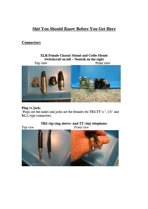
Shit You Should Know Before You Get Here ConnectorsXLR Female Chassis Mount and Cable MountSwitchcraft on left – Neutrik on the rightTop view Front viewPlug vs Jack:Plugs are the males and jacks are the females for TRS,TT ¼”, 1/8” and RCA type connectors.TRS (tip-ring-sleeve) And TT (tiny telephone)Top view Front viewTRS FemaleIn a rack panel In a patcbayRCA Connectors Pair Top View Side ViewRCA Connector pairFemale chassis mountBanana ConnectorsDual front view Dual top viewDual back view Single connectors¼” PlugsMono (guitar cable) and Stereo (headphone cable)The right side connector is NOTa TRS connector, it is a stereo ¼” connector¼” jacksMono and StereoFront view Top view1/8” PlugsTop View Front ViewIf you want to see the female connector or jack, look at your iPod or smart phone.BNC connectorsFemale front view Female side viewMale front viewMales are generally found as chassis mount but also can be a gender changer. The example is a gender changer.Firewire connectors Front view Side ViewFirewire Camera Connector Front view Side ViewFirewire 800 connector Front view Side viewUSB connectorMale Type AUSB ConnectorFemale Type AUSB Type A and Type B Side view Front viewDB-15 connectors for RGB videoDVI connector for Digital Video computer monitorHDMI connectors for HD videoMale cable end, side view Male cable end, front viewFemale couple, front viewGenerally video cables are male at both ends and the females are chassis mount as inputs or outputs to and from equipment. In the above examples, the females are from gender changers or convertor pigtails’Ground liftTop view Rear viewThese are used to lift the ground pin on the power cable. They are sometimes necessary to stop ground loops from happening. Ground loops produce audio hum.Gender Changers:These are used when the cable end is not the correct gender to connect what you are trying to connect or if you want to extend the cable by connecting two cables together and the connectors do not mate.Other Stuff:A pop filter is used to prevent excess wind noise and popping from a person speaking or singing into a microphone.Sometimes foam rubber ones are used but not advised for condenser mics because they deposit bits of foam on the capsule and cut the high frequency. The foam rubber ones are often called windscreens.The pop filter is also used to prevent moisture from breath from depositing itself on the capsule of condenser mics.This is what the pop filters we use look like:Nylon pop filter Nylon pop filter mounting hardwareMemory Stick or Flash DriveTop view, connectors out Tope view, connectors inFront viewIlok key’sOld style New StyleAn ilok is a green key-looking device (old style) or a Black USB unit that looks like a flash drive. It holds licenses for software. We have several of them. One for each HD machine that authorizes use of Protools and several “floating” iloks that have plug-in licenses on them. They have the name of the ilok on a label on the side and have a lanyard attached to them.Unbalanced Vs Balanced:A balanced connection refers to an audio high, audio low and a shield or ground. The shield or ground is not part of the audio connections; it is just there to shield the low level signal. An example of a balanced connector would be an XLR connector. An unbalanced connection refers to just audio high and ground, so there are only two connections, not three. The ground is used as the audio low and the shield. An example of an unbalanced connector would be an RCA connector.-10 to + 4 boxVersion one with cables Version one without cablesVersion two , front view Version two rca in rear viewA -10 to +4 box is a device that converts audio from -10dbv unbalanced to +4 dbm balanced audio. These are used to convert signal from consumer devices like iPods, CD players, audio out of DVD players and some keyboards that have unbalance outputs. The conversion is of level, unbalanced to balanced and impedance matching. All of this is done to get full range audio to professional line input level.Music stand lightThese are used by musicians for reading music notation or scripts and provide direct lighting in dimly lit rooms.Mic stands and boom standsExtra Boom stands hung up Two mic stands with booms.Type of MicrophonesFor the most part there are three types of mics used here:DynamicRibbonCondenserThe dynamic mics and, for the most part, ribbon mics are passive. They don’t need powering. This means they are usually not as loud as condenser mics.Condenser mics have amplifiers in them and, therefore need powering of some sort. If a mic is a condenser and the connector is a 3 pin XLR, it needs phantom power or some sort of battery.Phantom power:Phantom power is a powering system that has equal voltage (48vdc) on both the audio pins of the XLR. These are pins 2 and 3. The ground for the dc of phantom power is pin 1 on the XLR. The audio signal rides on top of the 48 volt phantom.If it has more than three pins (like 5 or 6 pins) and has a separate box that goes with it, it’s a tube condenser mic. We keep our tube condenser mics in separate cases. Each mic has a case with it’s power supply and cable. Condenser mics are usually louder so don’t connect them to a pre amp when the gain is turned up loud. Also don’t disconnect any mic with phantom power unless the phantom is turned off because it will pop in the speakers. Condenser mics sometimes have shock mounts that are specific to that mic A shock mount is a device that allows the mic to be mounted on a mic stand but shields the mic from floor vibration made by people walking by the mic or tapping their feet to the beat of the music.Microphone shock mountThere are many different kinds but they generally have bungee cord or rubber grommet material for the shock protection. The above example is a Neumann shock mount used for a U87 or U-67.A CD-R holds approximately 700 Mb and a DVD-R holds approximately 4.7Gb of data.CD-R in a 50 pack DVD-RThey both come in white that are printableWe give them with a jewel caseDVD+R and DVD-R in 100 pack rolls。
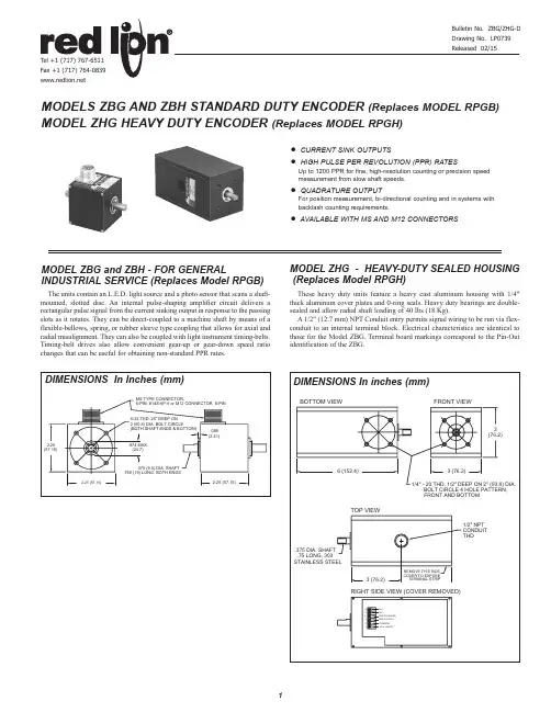
These heavy duty units feature a heavy cast aluminum housing with 1/4"thick aluminum cover plates and 0-ring seals. Heavy duty bearings are double-sealed and allow radial shaft loading of 40 lbs (18 Kg).A 1/2" (12.7 mm) NPT Conduit entry permits signal wiring to be run via flex-conduit to an internal terminal block. Electrical characteristics are identical tothose for the Model ZBG. Terminal board markings correspond to the Pin-Outidentification of the ZBG.● CURRENT SINK OUTPUTS● HIGH PULSE PER REVOLUTION (PPR) RATESUp to 1200 PPR for fine, high-resolution counting or precision speedmeasurement from slow shaft speeds.● QUADRATURE OUTPUTFor position measurement, bi-directional counting and in systems withbacklash counting requirements.● AVAILABLE WITH MS AND M12 CONNECTORS MODELS ZBG AND ZBH STANDARD DUTY ENCODER (Replaces MODEL RPGB) MODEL ZHG HEAVY DUTY ENCODER (Replaces MODEL RPGH)The units contain an L.E.D. light source and a photo sensor that scans a shaft-mounted, slotted disc. An internal pulse-shaping amplifier circuit delivers arectangular pulse signal from the current sinking output in response to the passingslots as it rotates. They can be direct-coupled to a machine shaft by means of aflexible-bellows, spring, or rubber sleeve type coupling that allows for axial andradial misalignment. They can also be coupled with light instrument timing-belts.Timing-belt drives also allow convenient gear-up or gear-down speed ratiochanges that can be useful for obtaining non-standard PPR rates.MODEL ZHG - HEAVY-DUTY SEALED HOUSING(Replaces Model RPGH)MODEL ZBG and ZBH - FOR GENERALINDUSTRIAL SERVICE (Replaces Model RPGB)SPECIFICATIONSELECTRICAL SPECIFICATIONS1. SUPPLY VOLTAGE :+4.75to+*******************°Cto85°C +4.75to+*******************°Cto100°C 2. OUTPUT : Current SinkingZBG and ZHG (Single Channel): 250 mA max.ZBH (Quadrature): 250 mA max. current per output. Incremental - two square waves in quadrature with Channel A leading Channel B for clockwise rotation. (Quad. Phase relationship is 90° ±22.5 electrical degrees)Note: NPN Transistor outputs have 1.5 K Ω load resistors returned to supply for internal feed back purposes. This does not interfere with the ability to use these outputs as conventional “Open-Collector” outputs as long as the supply voltage for the ZB is supplied by the indicator or control receiving its output signal. The ZB’s internal load resistor also allows the output to be used as a current source, however, load current must be limited to 1 mA max.3. MAXIMUM FREQUENCY :Single Channel : 20 KHz Quadrature : 20 KHzPPR available up to 1270 for both single channel and quadrature.MECHANICAL SPECIFICATIONS1. MAXIMUM SHAFT SPEED : 6000 RPM2. SHAFT DIAMETER : 0.375" (9.5 mm)3. RADIAL SHAFT LOAD : 40 lbs. operating (18 kg)4. AXIAL SHAFT LOAD : 30 lbs operating (13.6 kg)5. STARTING TORQUE :ZBG & ZBH : 0.38 oz-in (2.68 N-mm)ZHG : 3 oz-in (21.18 N-mm)6. MOMENT OF INERTIA : 6.5 x 10⁻⁶ oz-in-sec 27. CONNECTIONS : 6-pin MS style or 8-Pin M12 connector. (Male) Mating connector and cable assembly sold separately. For wiring cofiguration, see Cable Connections. For Ordering Information, see Accessories.8. HOUSING : Black non-corrosive finished 6063-T6 aluminum.9. BEARINGS : ABEC3 double sealed ball bearings 10. WEIGHT :ZBG & ZBH : 10 oz (283.5 g)ZHG : 3.8 lbs (1.72 Kg)ENVIRONMENTAL SPECIFICATIONS1. OPERATING TEMPERATURE : 0° to 100°C (See supply voltage)2. STORAGE TEMPERATURE : -25°C to +85°C 3. HUMIDITY : 98% RH non-condensing 4. VIBRATION : 10 g @ 58 to 500 Hz 5. SHOCK : 50 g @ 11 msec durationORDERING INFORMATIONNote: Only factory stocked part numbers are listed. Consult factory for part number and availability of other PPR and output configurations.Cable ConnectionsThe tables below list the pin connections from the ZBG and ZHG single channel and ZBH quadrature encoder to the optional CCARPG or CCM cable.ACCESSORIESDo not dispose of unit in trash - RecycleThe tubular arm length of this bracket, related to the wheel axis center-line of the encoder is 6.8" similar to the length sensors. The 10´ long, 4-wire, shielded cable with 6-pin MS connector (included with conversion bracket) has the same color coding as described for the encoder cable P/N CCARPG01. Screws for mounting the conversion bracket are included.ORDERING INFORMATIONMODEL NO.DESCRIPTIONPART NUMBERLSCBLength Sensor Conversion Bracket, w/10' CableLSCB1000Length Sensor Conversion Bracket, w/25' Cable LSCB1025Length Sensor Conversion Bracket, w/50' CableLSCB1050--Hinge Clamp Assembly for Length Sensors & Conversion Bracket (Above)LSAHC001LENGTH SENSOR MEASUREMENT ACCURACYFactors which affect measurement accuracy include Measuring Wheel accuracy and wear, and material conditions. Ideally, materials which are hard, thin and strong provide good readings, conversely, soft, thick and elastic materials can present problems in obtaining true readings. The great majority of these situations, where this effect is consistant, can be compensated for by applying a multiplier to the quadrature output pulse train so as to obtain a corrected measurement. Counter or Rate Indicators with “input scaling” can compensate for Measuring Wheel wear and material elastic and compliance errors. In addition, English/Metric conversions may also be accomplished (See RLC catalog for more information).When the desired output of a length sensor and wheel combination is either in feet or inch units, selection of the proper combination is relatively straight forward. For example, with a 1-foot wheel circumference, a 1 PPR Rotary Pulse Generator will deliver 1 pulse/ft, 12 PPR would deliver 12 pulses/ft (1 pulse/inch); 100 PPR would yield 100 pulses/ft; and 120 PPR would permit measuring to 1/10th of an inch (1/120th of a foot).SELECTING APPROPRIATE WHEEL SIZE & PPR (Pulses Per Rev.) OF ROTARY PULSE GENERATORLENGTH SENSOR ACCESSORIESSEPARATE LENGTH MEASURING WHEELS - DIMENSIONS In Inches (mm)Note: After installation of measuring wheels, ensure guards,shields or otherdevices are in place to protect personnel from rotating equipment.WHEELS & REPLACEMENT TIRES FOR CODE OR WHEELSRed Lion Controls Headquarters20 Willow Springs Circle York PA 17406Tel +1 (717) 767-6511Fax +1 (717) 764-0839Red Lion ControlsChinaUnit 302, XinAn PlazaBuilding 13, No.99 Tianzhou RoadShangHai, P .R. China 200223Tel +86 21 6113 3688Fax +86 21 6113 3683Red Lion ControlsEurope Softwareweg 9NL - 3821 BN Amersfoort Tel +31 (0) 334 723 225Fax +31 (0) 334 893 793Red Lion ControlsIndia201-B, 2nd Floor , Park Centra Opp 32 Mile Stone, Sector-30Gurgaon-122002 Haryana, IndiaTel +91 984 487 0503。


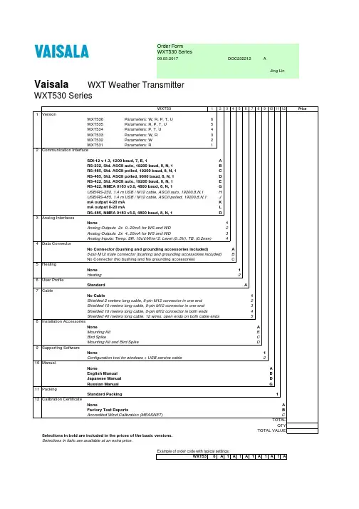
Order FormWXT530 Series09.03.2017DOC232212AJing Lin Vaisala WXT Weather TransmitterWXT530 SeriesWXT53123456789101112Price 1VersionWXT536Parameters: W, R, P, T, U6WXT535Parameters: R, P, T, U5WXT534Parameters: P, T, U4WXT533Parameters: W, R3WXT532Parameters: W2WXT531Parameters: R12Communication InterfaceSDI-12 v 1.3, 1200 baud, 7, E, 1ARS-232, Std. ASCII auto, 19200 baud, 8, N, 1BRS-485, Std. ASCII polled, 19200 baud, 8, N, 1CRS-485, Std. ASCII polled, 9600 baud, 8, N, 1DRS-422, Std. ASCII auto, 19200 baud, 8, N, 1ERS-422, NMEA 0183 v3.0, 4800 baud, 8, N, 1GUSB/RS-232, 1.4 m USB / M12 cable, ASCII auto, 19200,8,N,1 HUSB/RS-485, 1.4 m USB / M12 cable, ASCII polled, 19200,8,N,1 JmA output 4-20 mA KmA output 0-20 mA LRS-485, NMEA 0183 v3.0, 4800 baud, 8, N, 1R3Analog InterfacesNone1Analog Outputs 2x 0..20mA for WS and WD2Analog Outputs 2x 4..20mA for WS and WD3Analog Inputs: Temp. SR. 10uV/W/m^2, Level (0..5V), TB. (0.2mm)44Data ConnectorNo Connector (bushing and grounding accessories included)A8-pin M12 male connector (bushing and grounding accessories included)BNo Connector (No bushing and No grounding accessories)C5HeatingNone1Heating26User ProfileStandard A7CableNo Cable1Shielded 2 meters long cable, 8-pin M12 connector in one end2Shielded 10 meters long cable, 8-pin M12 connector in one end3Shielded 10 meters long cable, 8-pin M12 connector in both ends4Shielded 40 meters long cable, 12 wires, open ends on both cable ends58Installation AccessoriesNone AMounting Kit BBird Spike CMounting Kit and Bird Spike D9Supporting SoftwareNone1Configuration tool for windows + USB service cable210ManualNone AEnglish Manual BJapanese Manual DRussian Manual G11PackingStandard Packing112Calibration CertificateNone AFactory Test Reports BAccredited Wind Calibration (MEASNET)CTOTALQTYTOTAL VALUE Selections in bold are included in the prices of the basic versions.Selections in italic are available at an extra price.Example of order code with typical settings:WXT536A1A1A1A1A1AACCESSORIES & SPARE PARTS220614Vaisala Configuration Tool, USB Service cable SP220782Cable USB RS-232/485, 1.4m USB / M12 SP222287Cable 2m Shielded 8-pin M12 SP222288Cable 10m Shielded 8-pin M12 SP215952Cable 10m Shielded 8-pin M12, connectors on both ends SP 217020Cable 40m Shielded 12-pin, open end wires SP222109Bushing & Grounding Accessory Kit212792Mounting KitWMSFIX60Mounting Accessory between Mounting kit and 60mm tube 212793Bird KitWSP150Vaisala Surge Protector, no connectorsWSP152Vaisala Surge Protector with connectors for 220782 and 215952 229104Nokeval Converter229110Nokeval Programming Kit218817SP WXT Radiation Shield Set SPWXTPTUSP WXT PTU-Module SP224171WXT Bottom Connector Kit SP214273Analog input connector SP, IP67, 8P,M12,ShieldedWXT530BOTTOMDIGISP WXT530 Bottom Assy with Digital Board SPWXT530BOTTOMANAINSP WXT530 Bottom Assy with Analog Input Board SPWXT530BOTTOMMAOUTSP WXT530 Bottom Assy with mA Output Board SPTM-PT1000Module Temperature Sensor Assembly TM-PT1000。
sSINAMICS G120XA PN 变频器简明操作说明SINAMICS G120XA PN Converter Compact Operating Instructions04/2022不遵守安全说明和操作说明可导致生命危险本简明操作说明只包含操作变频器的重要信息。
若不遵守相关文档中的安全说明和操作说明,会导致人员重伤或死亡等事故。
• 遵守相关文档中的安全说明和安装说明。
• 参阅:https:///cs/cn/zh/ps/25530/manDanger to life if the safety instructions and operating instructions are not observedThe compact operating instructions only contain the most important information for operating the converter. If the safety instructions and operating instructions in the associated documentation are not observed, accidents involving severe injuries or death can occur.• Observe the safety instructions and operating instructions given in the associated documentation. • See also https:///cs/cn/en/ps/25530/man供货范围 Scope of delivery供货范围至少包括下列组件:• 带可运行固件的即连即用的变频器(变频器由功率模块以及不可拆卸的控制单元组成)。
关于固件升级和降级的方法可访问网址:https:///cs/cn/zh/ps/25530/dl• 一套用于连接 I/O 控制端子的连接器。
D3866-US-Rev C November 15, 2012John Deere 1990 30’ & 36’ CCS 1990 40’ & 44’ CCS1890 Version Planter ScaleInstructionsAnd Repair PartsFt. Atkinson, Wisconsin USAPanningen, The NetherlandsJohn Deere Planter Scale D3866-US-Rev AINTRODUCTION ............................................................................................................................................................................................... 1 Charging Battery and Welding ....................................................................................................................................................................... 1 SCALE BRACKET AND LOAD CELL MOUNTING INSTALLATION ................................................................................................................. 2 JUNCTION BOX MOUNTING ............................................................................................................................................................................ 5 Connect Load Cell and J-Box Cable .............................................................................................................................................................. 5 Installing wires into Terminal Block ................................................................................................................................................................ 5 INDICATOR MOUNTING ................................................................................................................................................................................... 6 Power Connection: ........................................................................................................................................................................................ 6 Load Cell Connection:.................................................................................................................................................................................... 6 TROUBLE SHOOTING ...................................................................................................................................................................................... 7 How to Check the Drill Scale after Installation ............................................................................................................................................... 7 REPAIR PARTS ................................................................................................................................................................................................ 8 406146 Kit – Scale JD1990 CCS Dual Rank 30’ ........................................................................................................................................... 8 406147 Kit – Scale JD1990 CCS Dual Rank 30’ (Indicator in cab) ................................................................................................................ 8 405942 Kit – Scale JD1990 CCS Dual Rank 40’ & 44’ .................................................................................................................................. 9 405943 Kit – Scale JD1990 CCS Dual Rank 40’ & 44’ (Indicator in cab) ....................................................................................................... 9 Indicator Swivel Mount ................................................................................................................................................................................. 10 LICENSE AGREEMENT . (11)All rights reserved. Reproduction of any part of this manual in any form whatsoever without Digi-Star’s express written permission is forbidden. The contents of this manual are subject to change without notice. All efforts have been made to assure the accuracy of the contents of this manual. However, should any errors be detected, Digi-Star would greatly appreciate being informed of them. The above notwithstanding, Digi-Star can assume no responsibility for errors in this manual or their consequence.© Copyright! 2008 Digi-Star, Fort Atkinson (U.S.A.).D3866-US-Rev A John Deere Planter Scale 1INTRODUCTIONCongratulations on the purchase of your new Digi-Star Planter Scale for John Deere 1990 30, 40 and 44 foot seeder. This manual is for 1890 version or dual rank units.The scale system is specially designed to weigh the central commodity seed hopper. The scale will record and monitor seed weigh going into or out of the CCS hopper.This scale system is covered by the following US patents: 6732667, 7059258 and 7273017. The single-use license is included with this document (see page 11).This SAFETY ALERT SYMBOL indicates important safety messages in the manual. When you see this symbol, be alert to the possibility of PERSONAL INJURY and carefully read the message that follows.NEVER OPERATE WITHOUT ALL COVERS, SHIELDS AND GUARDS IN PLACE. KEEPHANDS, FEET AND CLOTHING AWAY FROM MOVING PARTS. FAILURE TO HEED MAY RESULT INSERIOUS PERSONAL INJURY OR DEATH.Some covers and guards have been removed for illustrative/photographic purposes only in this manual.For information on ordering repair parts, refer to Parts Section in this book.This supersedes all previous published instructions. Important!Charging Battery and WeldingDisconnect all cables from the weighing indicator before charging the battery or welding on the machine. If cables are left connected, the weighing indicator and connected load cells could be damaged.Important: Do not weld near indicator, load cells or cables; remove from area to be welded. Place ground close to area to be welded to prevent current from passing through electronic parts.Scale Indicator Remote IndicatorOptionalJ-Box2John Deere Planter ScaleD3866-US-Rev ASCALE BRACKET AND LOAD CELL MOUNTING INSTALLATION1. Loosen the frame bolts on the front legs.2. Disassemble the rear legs and remove the angle bracket mounted to the leg and the main frame.3. Jack up one of the rear legs approximately 1 inch.Use Figure 1 for steps 4 - 74. Install and tighten the top bracket and hardware to the rear leg.5. Assemble load cell to the rear base bracket by using the 3/4 x 3 1/2 in. bolts. Do not tighten boltscompletely. You may have to slide load cell while aligning the base and top brackets. TOP DECAL NEEDS TO BE ON TOP OF LOAD CELL!6. Bolt the rear base bracket to the main frame using 5/8 x 11” bolt, two 5/8” flat washers, and 5/8” top-lock flange nut. Also, you will need to reuse one of the original frame bolts. Before installing add a 5/8” flat washer. Secure load cell to rear top bracket with 3/4 x 2” bolt. Apply thread lock to threads before installing. This bolt cannot be completely tightened; leave 1/16” between bottom of bolt head and top bracket.7. Install brackets on other side. Do not tighten mounting bolts on rear legs until front legs are installed. 8. Disassemble the front legs from base plates. Jack up front leg and remove the base plate and yoke plate bolted to the main frame.Figure 1Rear Leg Assembly JD 1990 Dual 30’, 40’ & 44’(Left Side Shown)Detail AD3866-US-Rev AJohn Deere Planter Scale3Use Figures 2 and 3 for steps 9 - 139. Install the front top bracket by using the 5/8 x 3 1/2” special bolts. The cropped bolt edge is installed next to the 4 x 4 tubing and from the top (see Figure 2). Install the front top bracket by using 5/8 x 2” bolt and two 5/8” washers, flange nut (see Figure 3).10. Assemble load cell to the front base plate by using 3/4 x 3 1/2 in. bolts and locknut. Do not tighten bolts completely. You may have to slide load cell while aligning base and top brackets. TOP DECAL NEEDS TO BE ON TOP OF LOAD CELL! (See Figure 2 or 3)11. Install front base plate weldment to the main frame with the yoke plate on the bottom. Reuse the original frame bolt (see Figure 2). Install front base plate weldment to the main frame with the supplied 5/8 x 8.75” U-bolts and 5/8 top lock flange nuts (see Figure 3).Figure 3Front Leg Assembly JD 1990 Dual 40’ & 44’ (Right Side Shown)Figure 2Front Leg Assembly JD 1990 Dual 30’ (Left Side Shown) NOTE: To make the front load cell support fit, the existing planter support pin may need to be modified. With a hand grinder, chamfer the bottom pin edge. IMPORTANT! Do not remove the existing support pin. The front pinis spring loaded.4 John Deere Planter Scale D3866-US-Rev A12. The load cell is held to the front top bracket with 3/4 x by 2 in. bolts. The 2 in. bolts need to have thread lock applied to the threads.THIS BOLT CAN NOT BE COMPLETELY TIGHTENED DOWN, LEAVE 1/16 in. BETWEEN BOTTOM OF BOLT HEAD AND TOP BRACKET!13. Install brackets on the other front leg. When all brackets are installed tighten all of the frame bolts, topbrackets and load cell bolts.14. Loosen the left and right hand rear ladder u-bolt so there is 1/8” minimum clearance. The u-bolt must notcontact the ladder tubing.D3866-US-Rev AJohn Deere Planter Scale5JUNCTION BOX MOUNTINGThe junction box is water resistant, not water-proof. It should be mounted to avoid submersion during wet weather and to avoid physical abuse. The junction box can be mounted on the front or rear of the drill, planter or seeder. All load cell cables must reach the J-Box. Install by removing the double sided tape backing and apply to cleaned surface. Connect Load Cell and J-Box Cable1. Route front and rear load cell cables to J-box location. Make sure they are not bound or pinched. Cable tie (customer provided) load cell cables in place.2. Insert load cell and J-box cables through each of the water-tight strain-reliefs.3. Remove each terminal block from the J-box.4. Connect wires of the same color to the same terminalblock. See instructions below.5. Install terminal block into the J-box as shown (location not important).6. Tighten nuts on the water-tight strain-reliefs.7. Assure that gasket is properly installed in the cover.8. Attach cover using 4 screws (provided).Installing wires into Terminal Block1. Open levers 90º to locked position.2. Insert individual wires into terminal.3. Close lever.4. Tug wire to assure solid connection.Note: Wire strip length is 7/16” (11mm).406232J-Box Lever Nut 4Pt (Planter)141837 Cable - 30Ft J-Box 406074 Cable - 45Ft J-Box 403335 Cable - Power 17Ft 2-Wire 406073 Cable - Power 36Ft 2-Wire 406072 Cable - Power 6Ft 2-Wire 824316 Cable - 15FT-J-Box 145096 Cable - 70FT-J-Box 406276 Cable – Power 65FT 2-Wire6John Deere Planter ScaleD3866-US-Rev AINDICATOR MOUNTINGThe scale indicator can be mounted in the tractor cab or on the drill, planter or seeder with swivel mounting pack (406081). Two cables must be connected to the indicator bottom panel, J-Box and power cables. Refer to Indicator Manual D3831-US for details of indicator mounting options and connection of power cord.1. Bolt the readout in the cab, or mount the swivel bracket on the drill, planter or seeder.2. Install power cord to a 12-volt negative ground battery.3. Route J-box cable to indicator and install to indicator bottom panel.4. Program indicator with set-up #145016 and calibration #15000 (see Indicator Manual)Power Connection:The power cable should be connected directly to a vehicle battery or regulated power supply. The scale end of the power cable is attached to the J901 connector located on the bottom panel of the indicator.Connect the RED wire from the power cable to +12 VDC and the BLACK wire to GROUND. The indicator is fused internally at 4 amps.Power Cable Connections: Wire color Wire Function Red Battery (+12 VDC) Black GROUNDLoad Cell Connection:The indicator is designed to operate with strain gage load cells. The indicator will normally be supplied with a “J-BOX” cable going between the scale and the load cell junction box. Extension kits are available from your dealer in various lengths. Load Cell Wire Digi-StarFunction1RED+EX 2 GREEN -SIG 3 WHITE +SIG 4 BLACK -EX 5CLEAR SHIELDPLANTER MOUNTING TRACTOR CAB MOUNTING INDICATOR MOUNTINGSD3866-US-Rev A John Deere Planter Scale 7TROUBLE SHOOTINGHow to Check the Drill Scale after InstallationFor the first test, lift the drill, planter or seeder all the way up, to a level area. Put 200-250 pounds of weight on the right side, then compare it to the left. Both sides should be within four to six pounds of each other.• If the weight is not within the four to six pound range, inspect the scale system for loose or misalignmounts.The second test is to lift the drill, planter or seeder to a level area and zero the scale. Lift thedrill/planter/seeder up and down two to three times, checking to see if the scale zeros out. Each time the scale is in the up position, it should be within four to six pounds.If further assistance is necessary, please call Digi-Star, LLC at 920-563-9700.8John Deere Planter Scale D3866-US-Rev AREPAIR PARTS406146 Kit – Scale JD1990 CCS Dual Rank 30’406147 Kit – Scale JD1990 CCS Dual Rank 30’ (Indicator in cab)KEYQTY.PART NO.DESCRIPTION1 2 406031 Weld-Top Rear Brkt (JD1990-03) 2 2 406051 Weld-Top Frt Brkt (JD1990-05) 3 2 406014 Weld-30’ Frt Brkt (JD1990-02) 4 1 406021 Weld-30’ LH Rear Leg (JD1990-01) 5 1 406017 Weld-30’ RH Rear Leg (JD1990-04)6 4 406067 Scr-3/4-16 x 2.0 HHCS Zp Grd 5 78 406068 Scr-3/4-10 x 3.5 HHCS Grd 8 ZP 8 8 405896 Scr-5/8-11 x 2.0 HHCS Zp Grd 59 4 406071 Scr–5/8-11 x 3.5 HHCS Zp Special 10 2 406069 Scr-5/8-11 x 11.0 HHCS Zp Grd 5 11 22 405858 Wash-5/8 Flat Wide Zp 12 8 405921 Nut-3/4-10 Top Lock Zp13 14 406070 Nut-5/8-11 Top-Lock Flange Zp 14 4 404284 Cell-1.5 Sq DB-21 FtD3866-US-Rev A John Deere Planter Scale 9405942 Kit – Scale JD1990 CCS Dual Rank 40’ & 44’405943 Kit – Scale JD1990 CCS Dual Rank 40’ & 44’ (Indicator in cab)KEY QTY. PART NO. DESCRIPTION 14 406031 Weld-Top Rear Brkt (JD1990-03) 22 406024 Weld-Base Rear Plate (JD1990-07) 31 406017 Weld-30’ RH Rear Leg (JD1990-04) 41 406021 Weld-30’ LH Rear Leg (JD1990-01) 54 406067 Scr - 3/4-16 x 2.0 HHCS Zp Grd5 68 406068 Scr - 3/4-10 x 3.5 HHCS Grd 8 Zp 716 405896 Scr – 5/8-11 x 2.0 HHCS Zp Grd 5 82 406069 Scr – 5/8-11 x 11.0 HHCS Zp Grd 5 932 405858 Wash – 5/8 Flat Wide Zp 108 405921 Nut – 3/4-10 Top Lock Zp 1126 406070 Nut – 5/8-11 Top-Lock Flange Zp 124 406025 Bolt-U 5/8-11 x 8.75W x 10.0L Grd 8 Zp 13 4 404284 Cell-1.5 Sq Db-21 Ft10 John Deere Planter Scale D3866-US-Rev A Indicator Swivel Mount406081 KEY QTY. PART NO. DESCRIPTION 1 1 403980 Brkt – Robo Mtg 2 2 406086 Brkt – Swivel Cast (JD H161618) 32 406087 Gasket – 1.813OD x 1.218 ID x .313 WID4 2 400036Scr – 1/4-20 x 3/4 HHCS ZP 5 2 400038Washer – Lock 1/4 ZP 6 2 400035Nut – 1/4-20 ZP72 405989Scr – 3/8-16 x 3.0 HHCS ZP Grd 58 2404292Nut – 3/8-16 Nyloc ZP 92 405612 GT400 Indicator (Not included in kit 406081)406385 KEYQTY. PART NO. DESCRIPTION 1 1 404230 Ram Suction Cup with Twist Lock 2 2 403180 Assembly – 1” Ram Mount 3 2 403779 Scr - #10 x 5/8 PHSTS 48-2 Blk ZPD3866-US-Rev A John Deere Planter Scale 11 LICENSE AGREEMENTIMPORTANT NOTICE: Acceptance and use of the enclosed electronic scale products (hereinafter referred to as “Purchased Product”) constitutes your agreement to the following terms and conditions. Please carefully read the following terms and conditions before using or reselling the Purchased Product. 1. Limited License. Digi-Star, LLC, a Wisconsin limited liability company (“Owner”) is the owner of the following U.S. Patents related to grain drills: 6,732,667, 7,059,258, 7,273,017, 7,357,087, 7,448,335, 7,523,710 and any other patents which result from continuation applications thereof (“Patents”). Owner hereby grants to the customer (“Customer”) a non-exclusive, non-transferable, revocable, limited license to use the technology described in the Patents to use the Purchased Product to assemble a seed planter product covered by the Patents (“Licensed Product”), and to sell and offer for sale one (1) unit of the Licensed Product in accordance with the terms and conditions set forth herein. Alternatively, Customer may resell the Purchased Product to another entity for the purpose of that entity assembling one (1) unit of a Licensed Product under a permitted sublicense from the Customer with the same terms as this Agreement. If Customer would like to assemble, use, sell or offer for sale more than one (1) Licensed Product, or resell more than one (1) Purchased Product, Customer understands and agrees that it must purchase another Purchased Product from Owner or acquire a separate license by requesting and purchasing another unit of the same SKU number that resulted in this purchase. 2. Acceptance of Terms and Conditions. Customer warrants that it has the authority to enter into this binding agreement. If Customer does not accept the terms and conditions, Customer shall not use the Purchased Product. Customer understands and agrees that if it uses the Purchased Product as permitted herein, it will be deemed to have accepted these terms and conditions and they shall become a binding agreement. 3. Limitations on Use. Customer agrees that it will use the Licensed Product only as expressly authorized in this Agreement, and that any use not expressly authorized in this Agreement is prohibited. Customer agrees that it will not: (i) loan, rent, lease, assign, sublicense, distribute or otherwise transfer its rights under this Agreement to a third party, other than to resell the Purchased Product to another entity for the purpose of that entity assembling one unit of a Licensed Product; (ii) copy or reproduce the Licensed Product; or (iii) grant any sublicenses other than to an end user of the Licensed Product, or to another entity for the purpose of that entity assembling one unit of a Licensed Product. Customer agrees to use reasonable efforts to prevent any unauthorized use or copying of the Licensed Product and will notify Owner immediately upon learning of any such unauthorized use or copying. Customer’s obligations under this section shall survive any termination of this Agreement or the license granted hereunder. Any unauthorized use of the Licensed Product will result in, among other things, the immediate termination of this license. 4. Ownership of Proprietary Rights. Customer acknowledges that the Licensed Product is covered intellectual and/or proprietary rights, and that all such intellectual and proprietary rights are owned by Owner. Customer hereby acknowledges that it has no rights in the foregoing except as expressly granted herein. 5. NO WARRANTY. Customer agrees to fully test and evaluate the Purchased Product and Customer acknowledges and agrees that Owner will not assume any product liability or any otherliability for the Purchased Product or the Licensed Product. The Purchased Product is furnished to Customer “AS IS.” Except as otherwise provided by separate documentation , OWNER MAKES NO WARRANTIES, EITHER EXPRESS OR IMPLIED, WITH RESPECT TO THE PURCHASED PRODUCT. Customer agrees that Owner shall have no liability resulting from Customer’s use of the Purchased Product for any indirect damages including consequential, incidental or special damages for loss of profit, good will or otherwise. Customer shall indemnify and hold Owner harmless from any and all losses, expenses, damages, costs or expenses of any kind, including but not limited to reasonable attorneys’ fees, incurred by Owner resulting from Customer’s use of the Purchased Product. NO ORAL OR WRITTEN STATEMENTS MADE BY OWNER OR ITS EMPLOYEES INCLUDING BUT NOT LIMITED TO STATEMENTS REGARDING CAPACITY, SUITABILITY FOR USE, OR PERFORMANCE OF THE PURCHASED PRODUCT SHALL BE DEEMED A WARRANTY OR REPRESENTATION BY OWNER FOR ANY PURPOSE NOR GIVE RISE TO ANY LIABILITY OR OBLIGATION OF OWNER. 6. Remedies for Violations . Owner reserves the right to seek all remedies available at law and in equity for violations of this Agreement, including but not limited to the right to recover the Licensed Product. 7. Fees. In consideration for the rights granted under this Agreement, Customer has paid a license fee that was included in the amount invoiced to the Customer for the sale of the Purchased Product. 8. Entire Agreement. Except as expressly stated herein to the contrary, this Agreement constitutes the entire agreement between the parties regarding the subject matter hereof, and no verbal or written prior statements or representations of any sort made by any party shall be effective or valid for any purpose whatsoever. This Agreement may be amended only upon the mutual consent of all parties in writing. 9. Severability. If any provision of this Agreement shall be held to be invalid, illegal or unenforceable, the validity, legality and enforceability of the remaining provisions shall not in any way be affected or impaired thereby. The failure of any party to enforce any provision of this Agreement shall not be considered a waiver thereof, nor shall such failure prevent the future enforcement of any such provision. 10. Governing Law. This Agreement and the relationship between the parties shall be governed in all respects by the laws of the State of Wisconsin and the United States of America. The parties consent to the jurisdiction and venue of the Wisconsin and United States courts located in Wisconsin for resolution of any dispute under to this Agreement Use or sale of the Licensed Product or of Purchased Product shall bind Customer to all terms and conditions herein without the necessity of signatures on this Agreement.。
Size 46-20-145 | 48-20-145Color SmokeTemple Standard | Cable 170mmSide Shields Brow Guard | Breeze Catcher | Perforated Full-Cup F9800PENTAXSmoke w. Breeze Catcher Side ShieldsF9900PENTAXSize 50-22-145 | 52-22-145Color SmokeTemple Standard | Cable 170mmSide Shields Brow Guard | Breeze Catcher | Perforated Full-CupSmoke w. Perforated Full-Cup Side ShieldsA2500PENTAXSize 55-19-131 | 58-20-131Color Black/Gray Temple Standard Side Shields IntegratedEAGLEPENTAXSize 53-13-adj | 56-11-adj | 59-13-adj Color SmokeTemple Adjustable Side Shields IntegratedF6000PENTAXSize 50-13-140 | 53-15-140 | 55-15-145Color Gray FadeTemple Standard | Cable 170mmSide Shields Brow Guard | Breeze CatcherA2000PENTAXSize 54-17-122 | 58-17-122 Color SmokeTemple Standard Side Shields Integrated All frames listed in this guide have been tested to and meetthe current ANSI Z87.1 standards.Key:These frames have passed a modified ASTM D149-09 test for dielectric strength and did not conduct electricity up to 1,000 volts for60 seconds or non-conductive by design (no metal parts).These frames are designed to wrap around the face and/or sealsto help the frame fit closer to wearer’s face.GUARDIANSafeVisionIncludes Removable Foam Dust Dam Size 58-17-118Color Carbon Fiber / Clear Temple Standard Side Shields IntegratedBrow GuardSmoke w. Breeze Catcher Side ShieldsBrow Guard Brow GuardSmokeSmokeCarbon Fiber / ClearBlack/GrayDELTASafeVisionSize 54-18-135Color Black/Clear | Dark Brown Stripe | Tortoise/OrangeTemple StandardSide Shields StandardDark Brown StripeZT100PENTAXSize 53-15-adj | 57-15-adj | 62-15-adjColor Black | Blue/Gray | Gray/RedTemple AdjustableSide Shields *Clear(*Permanently Attached Only)Blue/GrayALPHA-SVSafeVisionSize 56-17-128Color Matte Black | Black/Blue | Gray | Demi PurpleTemple StandardSide Shields StandardGrayFOXTROTSafeVisionSize 56-20-140Color Brown | GrayTemple StandardSide Shields StandardBrownSIDEWINDERSafeVisionSize 57-18-138Color Blue | Tortoise | Brown StripeTemple StandardSide Shields StandardBlueECHOSafeVisionSize 54-20-139Color Matte Black | Tortoise to Black | Espresso BrownTemple StandardSide Shields StandardTortoise to BlackUVERSESafeVisionSize 54-18-131Color Black/Clear | Wine/Clear | Copper/ClearTemple StandardSide Shields IntegratedCopper/ClearCARRIERSafeVisionSize 55-17-125Color Tortoise | PurpleTemple StandardSide Shields IntegratedTortoiseBETAPENTAXSize 56-18-140 | 58-18-145 | 60-18-145 Color Gunmetal | Black | Gold Temple Standard Side Shields Brow Guard Gold650PENTAXSize 48-16-140 | 50-16-145Color Brown Marble | Gray Marble Temple Spring Hinge Side Shields Brow GuardBrown MarbleGAMMAPENTAXSize 52-18-140 | 54-18-145Color Gunmetal | Gold Temple Standard Side Shields Brow Guard GoldD490PENTAXSize 54-16-140 | 56-16-145Color Black Crystal | Brown Amber Temple Standard Side Shields Brow Guard Black CrystalSVSS1SafeVisionSize 54-19-140Color Black/Blue | Brown/Red Temple Standard Side Shields StandardBrown/RedIncludes Removable Foam SealSize (6 Base) 56-21-127 | (8 Base) 61-19-127Color Matte Black | Camouflage Temple Standard Side Shields IntegratedZT25PENTAXCamouflageRx limitation for 8 base only: plus or minus 4.00D total power, including a -2.00D cylinder Phoenix & Poly Lenses ONLYZT200PENTAXIncludes Brow Protector & Lanyard Size 54-20-126Color Black/Lime Green w/ Crystal or Smoke | Gray/Y ellow w/ Crystal or Smoke | Blue w/ Crystal or Smoke | Purple w/ Crystal or Smoke | Camouflage w/ Crystal or Brown Temple Standard Side Shields IntegratedGray/Yellow w/ Crystal CarrierSV26SafeVisionIncludes Removable Full-Seal Rubber Gasket, Foam Dust Dam & Head Strap Size 57-20-124Color Turquoise/Orange | Shiny Black | Brown Temple Standard Side Shields IntegratedTurquoise/OrangeSize 57-17-129Color Smoke Crystal | Pink Cyrstal | Red/Flag | Blue/Flag | Clear | Black Temple Standard Side Shields IntegratedQUANTUMSafeVisionSmoke CrystalSVNYSafeVisionSize 62-16-111Color Shiny Black/Blue | Tortoise | Matte Black Temple Standard Side Shields Integrated Shiny Black/BlueCRUISERSafeVisionSize 57-18-126Blue/ClearIncludes Removable Full-Seal Rubber Gasket, Foam Dust Dam & Head Strap Size 55-18-132Color Black/Clear | Purple | Clear | Brown | Pink Temple Standard Side Shields Integrated SV20SafeVisionClearSize 57-18-140Color Satin Silver | Matte Brown Temple Standard Side Shields Standard SVSS11SafeVisionMatte BrownSVSS12SafeVisionSize 54-18-140Color Matte Black | Antique Silver Temple Standard Side Shields StandardAntique SilverSVSS14SafeVisionSize 54-18-140Color Matte Silver | Matte Blue Temple Standard Side Shields Standard Matte BlueSVSS3SafeVisionSize 53-17-140Color Gunmetal | Antique Bronze Temple Standard Side Shields StandardAntique BronzeSTREAKSafeVisionSize 63-18-122Color Matte Black | Silver | Red Temple Standard Side Shields IntegratedRedImage features Stainless Steel Attitude 6 framesSize 52-16-140Color Black/Blue | Tortoise/BrownTemple StandardSide Shields Brow GuardCLASSIC 10PENTAXBlack/BlueSize 53-17-135Color Brown Horn | Blue MarbleCLASSIC 12PENTAXBlue MarbleZT45PENTAXIncludes Removable Foam SealSize (6 Base) 54-13-130 (8 Base) 63-13-130Color Black w/ Black Graffiti | Silver | CamouflageTemple StandardSide Shields IntegratedBlack w/ Black GfraffitiPhoenix & Poly Lenses ONLYRx limitation for 8 base only:plus or minus 4.00D total power,including a -2.00D cylinder CamouflageIncludes Removable Rubber Seal & Temples + Temple Replacement Head Strap57-20-125Color Matte Gray (Black Trim) | Camouflage | Shiny Black (Blue Trim)Temple Standard removableSide Shields IntegratedZT35PENTAXIncludes Removable Foam SealSize 57-17-130Color Charcoal | Crystal w/ Gray Trim | Crystal w/ Orange TrimTemple Standard with flex tipSide Shields IntegratedCrystal w/ Orange Trim ZT55PENTAXPhoenix & Poly Lenses ONLYZT400PENTAXIncludes Head Strap attached at temple tip (foam seal available to purchase separately)Size 57-15-133Color Tan w/ Brown or Clear | Black w/ Smoke or Clear | Charcoal w/ Smoke or Clear |Navy w/ Smoke or ClearTemple Standard with flex tipSide Shields IntegratedNavy w/ Clear CarrierPhoenix & Poly Lenses ONLYOAKLEAFSafeVisionSize 60-24-124Color Matte Spider Web | Matte Black | Oakleaf Camo | Gloss Carbon Fiber | MatteCarbon FiberTemple StandardMatte Spider WebRANGERSafeVisionSize 62-18-121Color Matte Black | Crystal Blue | Crystal BrownTemple StandardSide Shields IntegratedCrystal BlueMISFIRESafeVisionIncludes Removable Foam Seal, Removable Full-Seal Rubber Gasket & Head Strap Size 64-18-110Color Pearl Brown / Blue | Matte Gunmetal Temple StandardSide Shields IntegratedPearl Brown / BlueBATTERYSafeVisionSize 65-16-120Color Gloss Black | Matte Navy | Matte Tortoise | Pearl/Orange Temple Standard Side Shields IntegratedMatte TortoiseMAXIM AIR SEAL RxPENTAXIncludes Air Bladder Seal, Removable Temples & Temple Replacement Head Strap Size 53-26-140Color BlackTemple Standard removableSide Shields IntegratedPhoenix & Poly Lenses ONLY Image features ZT35 framesBlackSTEEL 400PENTAXSize 49-19-140 | 51-19-145Color Gray Matte/Brown Matte | Brown Matte/Silver Matte Temple Spring HingeSide Shields Brow GuardStainless SteelGray Matte/Brown MatteIncludes Head Strap attached at temple tip Size 58-18-131Color Blue | Red Temple Standard Side Shields IntegratedZT500PENTAXRedZT500 non-conductive, no metal partsIncludes Removable Skirt Seal & Head Strap attached at mid temple Size 58-18-131Color Blue | RedTemple StandardSide Shields IntegratedZT500GPENTAXBlueZT500G non-conductive, no metal parts SVSR4SafeVisionSize 72-14-120Color Camo/Orange | Matte Gray Temple Standard Side Shields IntegratedCamo/OrangeRx limitations - Single Vision or Progressive lenses onlySVSR5SafeVisionSize 75-14-120Color Shiny Carbon | Matte Spider Web Temple Standard Side Shields IntegratedShiny CarbonRx limitations - Single Vision or Progressive lenses onlyImage features ZT500 framesATTITUDE 5PENTAXSize 54-18-140Color Matte-Gray front, Silver Temples | Matte-Brown front, Tortoise Temples Temple Spring Hinge Side Shields Brow Guard Stainless SteelMatte-Brown front, Tortoise TemplesATTITUDE 6PENTAXSize 48-16-130Color Matte-Brown front, Ocean Temples | Matte-Violet front, Pink Temples Temple Spring Hinge Side Shields Brow GuardStainless SteelMatte-Violet front, Pink TemplesREBELPENTAXSize 56-17-135Color Navy Blue | Gunmetal Temple Spring HingeSide Shields Brow Guard | Steel ShieldStainless SteelNavy Blue w. Steel Shield Side ShieldsHOGPENTAXSize 55-17-125 Color Black | Brown Temple Spring HingeSide Shields Brow Guard | Steel Shield Stainless SteelBlack w. Steel Shield Side ShieldsTRXPENTAXSize 57-17-135 | 59-17-140 Color Black | SilverTemple Spring HingeSide Shields TRX Brow Guard | Steel Shield Stainless SteelSilver w. Steel Shield Side ShieldsURBAN 6PENTAXSize 57-16-140 Color Black | Bronze Temple Spring Hinge Side Shields Brow GuardBronzeSVTI1SafeVisionSize 54-17-140Color Gunmetal | Antique Bronze Temple Standard Side Shields StandardAntique BronzeURBAN 8PENTAXSize 55-18-140Color Matte Black | Brown Temple Spring Hinge Side Shields Brow Guard Matte BlackSize 52-18-135 | 54-18-140 Color Moss/Dark Gunmetal | Burgundy/Silver Temple Spring Hinge Side Shields Brow Guard ATTITUDE 3PENTAX Stainless SteelPhoenix & Poly Lenses ONLY Burgundy/Silver SVTI11SafeVisionSize 54-19-140 Color Antique Gold | Matte Gray Temple Standard Side Shields StandardAntique Gold 7000SunwoodDrNW,Ramsey,MN55303|*******************|800-982-2828|©2023 Hoya Corporation. All rights reserved. | SafeVision Frame Group Guide | Lit Code: 34255 | January 2023Brow Guard • Made from high-impact polycarbonate • Available in clear or gray • Detachable Steel Shield (TRX, Rebel & Hog only)• Made of stainless steel • Colors to match frame • Oxidation & corrosion resistant • Provides ventilation and helps reduce fogging • DetachableBreeze Catcher (F9800, F9900 & F6000 only)• Wire mesh design provides ventilation and helps reduce fogging • Oxidized, corrosion resistant wire mesh • Full-cup design • Tighter-weave 40 mesh • Permanently attached Perforated Full-Cup (F9800 & F9900 only)• Made from propionate • Perforated design helps reduce fogging • Permanently attached。