IRLU7807Z中文资料
- 格式:pdf
- 大小:166.63 KB
- 文档页数:11

78070芯片介绍(ESOP-8)是一颗专用于便携式锂电池小风扇的驱动芯片,芯片集成锂电池充电管理、DC-DC 升压、手电筒照明、风量显示及低电提醒、按键换挡、过流保护、短路保护等功能。
标示信息78070F: 无铅封装类型 SP: ESOP-8应用范围✧ 便携式锂电池风扇特点◆ 800mA 锂电池充电,充电电流自适应 ◆ 高效率DC-DC 升压 ◆ 输出电压外部电阻可调◆ 3挡风量可调,3段式风量指示,2颗LED 充电指示 ◆ 内置手电筒驱动,全部内置电阻 ◆ 低待机功耗<15uA ◆ 支持双按键控制 ◆ 外围简单◆ 具有过流保护,短路保护,过温保护 ◆ 封装形式:ESOP-8丝印及包装信息引脚信息应用原理图V OUT=[1+(R1/R2)]×V FB三挡对应V FB为:0.6V,0.9V,1.2V极限参数✧VIN、BAT至GND ----------------------------------------------------------------------- -0.3V~+7V ✧SW至GND ----------------------------------------------------------------------------- -0.3V~+12V ✧FB至GND ------------------------------------------------------------------------------- -0.3V~+7V ✧DR至GND ----------------------------------------------------------------------------- -0.3V~+12V ✧最高结温 --------------------------------------------------------------------------------------- 125°C ✧最大焊接温度(引线处,10秒)---------------------------------------------------------------- 260°C ✧存储温度 ------------------------------------------------------------------------------- -55℃~150°CESD 系数✧人体模型(HBM) ------------------------------------------------------------------------------------------------------ 2KV ✧机械模型(MM) ------------------------------------------------------------------------------------------------------- 200V电气参数LED显示状态充电部分(STAT/FULL)挡位及手电部分(LED1/LED2/LED3/WLED)应用说明自适应充电控制78070内部集成了充电电流自适应功能,当适配器输出电流能力小于800mA或者输入线材内阻较大时,芯片通过检测输入电压,自动调整充电电流。

Illuminometer Model No. MP780118Read all instructions before using the appliance and retain for future reference.• Please follow all safety operation instructions.• Children should be supervised to ensure that they do not play with the product.• Do not use the monitor if the casing is damaged or there is any anomaly that may impair it’s function.• Do not use the product for any purpose other than that for which it is designed.• Do not operate the product around explosive gas, vapour, or dust.• Do not operate or store in an environment of high humidity or where moisture may enter the product.• Turn the meter off when not in use to save the battery.• Remove the battery if the monitor is not to be used for long periods.• Replace the battery as soon as the low battery warning appears on the display to avoid possible incorrect readings.•For indoor use only.PRODUCT OVERVIEWWHAT’S INCLUDED • Digital light meter • Instruction manual •BatteriesIMPORTANT SAFETY INFORMATION1. Maximum value2. Minimum value3. Data hold4. Low battery warning5. FC (foot/candle)6. LUX7. Reading x10 or x1008. Temperature value 9.Auto power off1. Display unit2. LCD screen3. Mode buttons4. Illumination sensor5. Protection cover6. Measuring probe7. Extendable cable• Clean the casing using a moist cloth and mild detergent. Do not use any form of solvents.• There are no user serviceable parts inside.•When the low battery symbol displays on the LCD, replace the three AAA batteries in the back of the meter to avoid any inaccuracies in readings taken.OPERATIONMAINTENANCE Power button• Press and hold the power button to turn the meter on.• Short press the power button to turn the meter off.• Press and hold the power button to enable or disable auto power off function.LUX/FC button• Short press to switch between units.Mode button• Short press to switch between max, min and normal value recorded. HOLD button• Short press to enable or disable the data hold function.• Press and hold to turn on or off the LCD backlight feature.Function DescriptionDisplay 4 digit LCD max display 9999Max/Min MAX or MIN is displayed Data hold HOLD symbol is displayed Overload alarm Over 199900 Lux - OL is displayed Backlight LCD Backlight on/off functionAuto power off The meter will turn the power off if not operated for approx 5 minutesSampling range Once per 0.5 second Drop test 1mAccuracy 0-9999 Lux ±(4%rdg+8dgts)>9999 Lux ±(5%rdg+10dgts) @ ambient temp 23o C ±3o C <80%RH Battery 1.5V 3 x AAAEnvironment Indoor 0o C~40o C (<90%RH)Storage Indoor -20o C~60o C (<75%RH)Altitude 2000m Pollution grade 2INFORMATION ON WASTE DISPOSAL FOR CONSUMERS OF ELECTRICAL & ELECTRONIC EQUIPMENT.These symbols indicate that separate collection of Waste Electrical and Electronic Equipment (WEEE) or waste batteries is required. Do not dispose of these items with general household waste. Separate for the treatment, recovery and recycling of the materials used. Waste batteries can be returned to any waste battery recycling point which are provided by most battery retailers. Contact your local authority for details of the battery and WEEE recycling schemes available inyour area.Made in China. LS12 2QQMan Rev 1.0SPECIFICATION Range Resolution Accuracy Note0~199,900Lux0~9999Lux 1 Lux ±(4%rdg+8dgts)Auto range switch >10,000Lux 10Lux ±(5%rdg+10dgts)>1000,000Lux100Lux±(5%rdg+10dgts)。

IR780结构式IR780是一种近红外(NIR)染料,具有广泛的应用潜力。
它的结构式如下所示:IR780的化学性质IR780属于吲哚类染料,其化学名为1,1’-二甲基-4,4’-聚(吲哚烷基)氧化物。
它是一种有机分子,由多个吲哚环组成,其中还含有甲基和氧原子。
IR780具有许多优异的化学性质。
首先,它具有很高的光稳定性,能够在强光照射下保持其染色性能。
其次,它在水中溶解度较低,但在非极性溶剂中溶解度较高。
这使得IR780可以在不同体系中应用,并且具有良好的稳定性。
IR780的光学特性由于其分子结构中含有共轭体系,使得IR780具有良好的光吸收和荧光发射特性。
它对近红外区域(700-900 nm)的光具有较高的吸收率,并且能够发射出可见光的荧光信号。
IR780的吸收峰位于780 nm附近,这使得它在近红外区域有很好的应用前景。
在医学领域,IR780可以作为光热治疗的荧光探针,用于肿瘤治疗。
它可以被激光器激发产生热能,从而杀死肿瘤细胞。
此外,IR780还可以作为近红外成像剂,用于肿瘤诊断和显像。
IR780在生物医学中的应用IR780在生物医学领域具有广泛的应用前景。
首先,由于其良好的光吸收特性和荧光发射特性,它可以作为近红外探针用于活体成像。
通过将IR780标记在分子或纳米粒子上,并通过靶向策略将其导向到特定组织或器官,可以实现对该组织或器官进行高分辨率的成像。
其次,由于其光热转换特性,IR780还可以用于肿瘤治疗。
当IR780被激光器激发时,会产生大量的热能,在肿瘤细胞中引起热损伤,从而达到治疗的效果。
这种光热治疗方法具有无创、可控和高效的特点,被广泛用于肿瘤治疗。
此外,IR780还可以用于药物递送系统。
通过将药物包裹在IR780修饰的纳米粒子中,并通过靶向策略将其导向到肿瘤组织,可以实现对肿瘤的精确治疗。
这种纳米粒子药物递送系统具有高效性和低毒性的特点,可以提高药物的生物利用度并减少副作用。
IR780在其他领域中的应用除了在生物医学领域中的应用之外,IR780还具有许多其他领域的应用潜力。

ir780的激发波长和发射波长下载提示:该文档是本店铺精心编制而成的,希望大家下载后,能够帮助大家解决实际问题。
文档下载后可定制修改,请根据实际需要进行调整和使用,谢谢!本店铺为大家提供各种类型的实用资料,如教育随笔、日记赏析、句子摘抄、古诗大全、经典美文、话题作文、工作总结、词语解析、文案摘录、其他资料等等,想了解不同资料格式和写法,敬请关注!Download tips: This document is carefully compiled by this editor. I hope that after you download it, it can help you solve practical problems. The document can be customized and modified after downloading, please adjust and use it according to actual needs, thank you! In addition, this shop provides you with various types of practical materials, such as educational essays, diary appreciation, sentence excerpts, ancient poems, classic articles, topic composition, work summary, word parsing, copy excerpts, other materials and so on, want to know different data formats and writing methods, please pay attention!了解IR780的激发波长和发射波长随着生物医学领域的不断发展,纳米技术和分子成像技术的兴起为医学诊断和治疗提供了新的可能性。


ParameterSymbol IRF7807IRF7807AUnits Drain-Source Voltage V DS 30VGate-Source Voltage V GS ±12Continuous Drain or Source 25°C I D8.38.3ACurrent (V GS ≥ 4.5V)70°C6.6 6.6Pulsed Drain Current I DM 6666Power Dissipation25°C P D 2.5W 70°C1.6Junction & Storage T emperature Range T J , T STG–55 to 150°C Continuous Source Current (Body Diode) I S 2.5 2.5APulsed source CurrentI SM6666•N Channel Application Specific MOSFETs •Ideal for Mobile DC-DC Converters •Low Conduction Losses •Low Switching LossesDescriptionThese new devices employ advanced HEXFET Power MOSFET technology to achieve an unprecedented balance of on-resistance and gate charge. The reduced conduction and switching losses make them ideal for high efficiency DC-DC Converters that power the latest generation of mobile microprocessors.A pair of IRF7807 devices provides the best cost/performance solution for system voltages, such as 3.3V and 5V .HEXFET ® Chip-Set for DC-DC ConvertersAbsolute Maximum Ratings ParameterMax.Units Maximum Junction-to-AmbientR θJA50°C/WThermal ResistanceIRF7807/IRF7807A 110/10/00IRF7807 IRF7807AVds 30V 30V Rds(on) 25m Ω 25m ΩQg 17nC 17nC Qsw 5.2nC Qoss 16.8nC 16.8nCDevice Features PD – 91747C2IRF7807/IRF7807AParameter MinTyp MaxMin Typ Max UnitsConditionsDiode Forward V SD 1.2 1.2V I S = 7A , V GS = 0V Voltage*Reverse Recovery Q rr 8080nCdi/dt = 700A/µsChargeV DS = 16V, V GS = 0V, I S = 7A Reverse Recovery Q rr(s)5050Charge (with Parallel Schotkky)ParameterMin Typ Max Min Typ Max Units ConditionsDrain-to-Source V (BR)DSS 30––30––V V GS = 0V , I D = 250µA Breakdown Voltage*Static Drain-Source R DS (on)17251725m ΩV GS = 4.5V , I D = 7A on Resistance*Gate Threshold Voltage*V GS (th) 1.01.0V V DS = V GS , I D = 250µA Drain-Source Leakage I DSS3030µAV DS = 24V , V GS = 0150150V DS = 24V , V GS = 0,Tj = 100°C Gate-Source Leakage I GSS ±100±100nAV GS = ±12V Current*T otal Gate Charge*Q g 12171217V GS = 5V, I D = 7A Pre-VthQ gs1 2.1 2.1V DS = 16V, I D = 7AGate-Source Charge Post-VthQ gs20.760.76nCGate-Source Charge Gate to Drain Charge Q gd 2.9 2.9Switch Charge*Q SW 3.66 5.2 3.66(Q gs2 + Q gd )Output Charge*Q oss 1416.81416.8V DS = 16V , V GS = 0Gate Resistance R g 1.2 1.2ΩT urn-on Delay Time t d (on)1212V DD = 16V Rise Timet r 1717nsI D = 7A T urn-off Delay Time t d (off)2525R g = 2ΩFall Timet f66V GS = 4.5V Resistive LoadElectrical Characteristics Source-Drain Rating & Characteristics Notes:Repetitive rating; pulse width limited by max. junction temperature. Pulse width ≤ 300 µs; duty cycle ≤ 2%.When mounted on 1 inch square copper board, t < 10 sec. Typ = measured - Q oss*Devices are 100% tested to these parameters.IRF7807IRF7807ACurrent*di/dt = 700A/µs (with 10BQ040)V DS = 16V , V GS = 0V, I S = 7A 3IRF7807/IRF7807AControl FETSpecial attention has been given to the power losses in the switching elements of the circuit - Q1 and Q2.Power losses in the high side switch Q1, also called the Control FET , are impacted by the R ds(on) of the MOSFET ,but these conduction losses are only about one half of the total losses.Power losses in the control switch Q1 are given by;P loss = P conduction + P switching + P drive + P outputThis can be expanded and approximated by;P loss =I rms 2×R ds(on)() +I ×Q gdi g ×V in ×f +I ×Q gs2i g ×V in ×f+Q g ×V g ×f () +Q oss2×V in ×fThis simplified loss equation includes the terms Q gs2and Q oss which are new to Power MOSFET data sheets.Q gs2 is a sub element of traditional gate-source charge that is included in all MOSFET data sheets. The impor-tance of splitting this gate-source charge into two sub elements, Q gs1 and Q gs2, can be seen from Fig 1.Q gs2 indicates the charge that must be supplied by the gate driver between the time that the threshold volt-age has been reached (t1) and the time the drain cur-rent rises to I dmax (t2) at which time the drain voltage begins to change. Minimizing Q gs2 is a critical factor in reducing switching losses in Q1.Q oss is the charge that must be supplied to the output capacitance of the MOSFET during every switching cycle. Figure 2 shows how Q oss is formed by the paral-lel combination of the voltage dependant (non-linear)capacitance’s C ds and C dg when multiplied by the power supply input buss voltage.Synchronous FETThe power loss equation for Q2 is approximated by;P loss =P conduction +P drive +P output*P loss =I rms 2×R ds(on)()+Q g ×V g ×f ()+Q oss 2×V in ×f+Q rr ×V in ×f ()*dissipated primarily in Q1.Power MOSFET Selection for DC/DC ConvertersIRF7807/IRF7807ATypical Mobile PC ApplicationFigure 2: Q oss CharacteristicFor the synchronous MOSFET Q2, R ds(on) is an im-portant characteristic; however, once again the impor-tance of gate charge must not be overlooked since it impacts three critical areas. Under light load the MOSFET must still be turned on and off by the con-trol IC so the gate drive losses become much more significant. Secondly, the output charge Q oss and re-verse recovery charge Q rr both generate losses that are transfered to Q1 and increase the dissipation in that device. Thirdly, gate charge will impact the MOSFETs’ susceptibility to Cdv/dt turn on.The drain of Q2 is connected to the switching node of the converter and therefore sees transitions be-tween ground and V in . As Q1 turns on and off there is a rate of change of drain voltage dV/dt which is ca-pacitively coupled to the gate of Q2 and can induce a voltage spike on the gate that is sufficient to turn the MOSFET on, resulting in shoot-through current .The ratio of Q gd /Q gs1 must be minimized to reduce the potential for Cdv/dt turn on.Spice model for IRF7807 can be downloaded in ma-chine readable format at .IRF7807/IRF7807AIRF7807/IRF7807A6IRF7807/IRF7807A Package OutlineSO-8 Outline78IRF7807/IRF7807ATape & Reel InformationSO-8Dimensions are shown in millimeters (inches)330.00(12.992) M AX.14.40 ( .566 )12.40 ( .488 )N O TE S :1. C O N TR O LLIN G D IM EN SIO N : M ILLIM ETER.2. O UTLIN E C O N FO RM S TO EIA -481 & EIA-541.FEED D IRE C TIO NTER M IN AL N U M BE R 112.3 ( .484 )11.7 ( .461 )8.1 ( .318 )7.9 ( .312 )N O TE S :1. C O N T R O L LIN G D IM E N S IO N : M ILL IM E T E R.2. A LL D IM E N S IO N S A RE S H O W N IN M ILL IM E T E R S (INC H E S ).3. O UT L IN EC O N F O R M S T O E IA -481 & E IA -541.IR WORLD HEADQUARTERS: 233 Kansas St., El Segundo, California 90245, USA Tel: (310) 252-7105IR EUROPEAN REGIONAL CENTRE: 439/445 Godstone Rd, Whyteleafe, Surrey CR3 OBL, UK Tel: ++ 44 (0)20 8645 8000IR CANADA: 15 Lincoln Court, Brampton, Ontario L6T3Z2, Tel: (905) 453 2200IR GERMANY: Saalburgstrasse 157, 61350 Bad Homburg Tel: ++ 49 (0) 6172 96590IR ITALY: Via Liguria 49, 10071 Borgaro, Torino Tel: ++ 39 011 451 0111IR JAPAN: K&H Bldg., 2F, 30-4 Nishi-Ikebukuro 3-Chome, Toshima-Ku, Tokyo 171 Tel: 81 (0)3 3983 0086IR SOUTHEAST ASIA: 1 Kim Seng Promenade, Great World City West Tower, 13-11, Singapore 237994 Tel: ++ 65 (0)838 4630IR TAIWAN:16 Fl. Suite D. 207, Sec. 2, Tun Haw South Road, Taipei, 10673 Tel: 886-(0)2 2377 9936Data and specifications subject to change without notice. 10/00。

IR780的分子量1. 什么是IR780?IR780是一种应用于生物医学领域的红外吸收染料,属于一种非常重要的小分子化合物。
它具有较高的光吸收能力和荧光发射特性,因此在肿瘤治疗、光动力疗法和生物成像等方面具有广泛的应用前景。
2. 分子式和结构IR780的分子式为C43H53N4O2S2,其结构如下所示:从结构上可以看出,IR780是一种有机化合物,主要由碳、氢、氮、氧和硫元素组成。
它具有多个芳香环,并且在分子中含有两个硫原子。
3. 分子量计算分子量是指一个化合物中所有原子相对原子质量之和。
对于IR780来说,我们可以通过计算每个原子的相对原子质量,并将它们相加得到其分子量。
根据元素周期表上相关数据,我们可以得到以下信息:•碳(C)的相对原子质量为12.01•氢(H)的相对原子质量为1.008•氮(N)的相对原子质量为14.01•氧(O)的相对原子质量为16.00•硫(S)的相对原子质量为32.07通过计算,我们可以得到IR780的分子量如下:(12.01 * 43) + (1.008 * 53) + (14.01 * 4) + (16.00 * 2) + (32.07 * 2) = 780.09 g/mol因此,IR780的分子量为780.09克/摩尔。
4. IR780的应用由于IR780具有较高的吸收和发射红外光能力,它在生物医学领域有着广泛的应用。
以下是一些IR780的主要应用领域:a. 肿瘤治疗IR780可以作为一种光敏剂,被用于肿瘤治疗中的光动力疗法。
在该疗法中,IR780会被注射到患者体内,并且会在肿瘤组织中积累。
随后,通过使用激光等外部能源来激活IR780,它会产生一种能够杀死癌细胞的活性氧物质。
这种方法可以有效地治疗肿瘤,并且对周围正常组织的损伤较小。
b. 生物成像IR780还可以用于生物成像,特别是近红外成像。
由于其在近红外光谱区域的吸收和发射特性,IR780可以用作一种荧光探针来标记生物分子或细胞。

7.6 mm (0.3 inch) Micro Bright Seven Segment Displays Technical DataFeatures• Available with Colon for Clock Display • Compact Package 0.300 x 0.500 inchesLeads on 2.54 mm (0.1 inch)Centers• Choice of Colors AlGaAs Red, HighEfficiency Red, Yellow, Green,Orange• Excellent Appearance Evenly Lighted Segments Mitered Corners on Segments Surface Color Gives Optimum Contrast±50° Viewing Angle • Design FlexibilityCommon Anode or Common CathodeRight Hand Decimal Point ±1. Overflow Character • Categorized for Luminous IntensityYellow and Green Categorized for ColorUse of Like Categories Yields a Uniform Display • High Light Output • High Peak Current• Excellent for Long Digit String Multiplexing • Intensity and Color Selection Available See Intensity and ColorSelected Displays Data Sheet • Sunlight Viewable AlGaAsDescriptionThe 7.6 mm (0.3 inch) LED seven segment displays are designed for viewing distances up to 3 metres (10 feet). These devices use an industry standard size package and pinout. Both the numeric andDevicesOrange AlGaAs [1]HER [1]Yellow [1]Green [1]Package HDSP-HDSP-HDSP-HDSP-HDSP- DescriptionDrawingA401A151750174017801Common Anode Right A Hand Decimal750274027802Common Anode Right Hand B Decimal, Colon A403A153750374037803Common Cathode Right C Hand Decimal750474047804Common Cathode Right Hand D Decimal, ColonA157750774077807Common Anode ±1. Overflow E A158750874087808Common Cathode ±1. OverflowFNote:1. These displays are recommended for high ambient light operation. Please refer to the HDSP-A10X AlGaAs, HDSP-335X HER, HDSP-A80X Yellow, and HDSP-A90X Green data sheet for low current operation.HDSP-740x Series HDSP-750x Series HDSP-780x Series HDSP-A15x Series HDSP-A40x Series±1. overflow devices feature a right hand decimal point. All devices are available as either common anode or common cathode.These displays are ideal for most applications. Pin for pin equiv-alent displays are also available in a low current design. The low current displays are ideal forportable applications. For additional information see the Low Current Seven Segment Displays.Part Numbering SystemNotes:1. For codes not listed in the figure above, please refer to the respective datasheet or contact your nearest Agilent representative for details.2. Bin options refer to shippable bins for a part number. Color and Intensity Bins are typically restricted to 1bin per tube (exceptions may apply). Please refer to respective datasheet for specific bin limit information.5082 -X X X X-X X X X X HDSP-X X X X-X X X X XMechanical Options [1]00: No Mechanical OptionColor Bin Options [1,2]0: No Color Bin Limitation3: Color Bins 3- and 3+ only (applicable for Yellow devices only)Z: Color Bins 2- and 3+ only (applicable for Yellow devices only)Maximum Intensity Bin [1,2]0: No Maximum Intensity Bin Limitation Minimum Intensity Bin [1,2]0: No Minimum Intensity Bin Limitation Device Configuration/Color [1]1: Common Anode 2: Common Anode 3: Common Cathode 4: Common CathodeDevice Specific Configuration [1]Refer to Respective DatasheetPackage [1]A: 7.6 mm (0.3 inch) Single Digit Seven Segment DisplayInternal Circuit DiagramA B C D EFPackage DimensionsNOTES:1. ALL DIMENSIONS IN MILLIMETRES (INCHES).2. MAXIMUM.3. ALL UNTOLERANCED DIMENSIONS ARE FOR REFERENCE ONLY.4. REDUNDANT ANODES.5. REDUNDANT CATHODES.6. FOR HDSP-7400/-7800 SERIES PRODUCT ONLY.Device Series HDSP-ParameterSymbol Min.Typ.Max.Units Test Conditions Luminous Intensity/Segment [1,2,5]I V6.914.0mcd I F = 20 mA (Digit Average)1.8VI F = 20 mAForward Voltage/Segment or DPV F2.03.0V I F = 100 mAA15xPeak Wavelength λPEAK 645nm Dominant Wavelength [3]λd 637nm Reverse Voltage/Segment or DP [4]V R 3.015.0V I R = 100 µA Temperature Coefficient of ∆V F /°C -2mV/°C V F /Segment or DPThermal Resistance LED Junction-R θJ-PIN255°C/W/Segto-PinAlGaAs RedElectrical/Optical Characteristics at T A = 25°C Absolute Maximum RatingsAlGaAs Red HER/Orange Yellow GreenHDSP-A150HDSP-7500/-A40X HDSP-7400HDSP-7800DescriptionSeriesSeries SeriesSeriesUnits Average Power per Segment or DP 9610580105mW Peak Forward Current per 160[1]90[3]60[5]90[7]mA Segment or DPDC Forward Current per 40[2]30[4]20[6]30[8]mASegment or DPOperating Temperature Range –20 to +100[9]–40 to +100°CStorage Temperature Range –55 to +100°C Reverse Voltage per Segment or DP 3.0V Lead Solder Temperature for 3Seconds (1.59 mm [0.063 in.] 260°Cbelow seating plane)Notes:1. See Figure 1 to establish pulsed conditions.2. Derate above 46°C at 0.54 mA/°C.3. See Figure 6 to establish pulsed conditions.4. Derate above 53°C at 0.45 mA/°C.5. See Figure 7 to establish pulsed conditions.6. Derate above 81°C at 0.52 mA/°C.7. See Figure 8 to establish pulsed conditions.8. Derate above 39°C at 0.37 mA/°C.9. For operation below –20°C, contact your local Agilent components sales office or an authorized distributor.High Efficiency RedDeviceSeriesHDSP-Parameter Symbol Min.Typ.Max.Units Test Conditions Luminous Intensity/Segment[1,2,6]360980I F = 5 mA(Digit Average)I Vµcd5390I F = 20 mA Forward Voltage/Segment or DP V F 2.0 2.5V I F = 20 mA 750x Peak WavelengthλPEAK635nmDominant Wavelength[3]λd626nmReverse Voltage/Segment or DP[4]V R 3.030V I R = 100 µATemperature Coefficient of∆V F/°C-2mV/°CV F/Segment or DPThermal Resistance LED Junction-RθJ-PIN200°C/W/Segto-PinOrangeDeviceSeriesHDSP-Parameter Symbol Min.Typ.Max.Units Test Conditions Luminous Intensity/Segment[1,2,6]I V0.70mcd I F = 5 mA(Digit Average)Forward Voltage/Segment or DP V F 2.0 2.5V I F = 20 mA A40x Peak WavelengthλPEAK600nmDominant Wavelength[3]λd603nmReverse Voltage/Segment or DP[4]V R 3.030V I R = 100 µATemperature Coefficient of∆V F/°C-2mV/°CV F/Segment or DPThermal Resistance LED Junction-RθJ-PIN200°C/W/Segto-PinYellowDeviceSeriesHDSP-Parameter Symbol Min.Typ.Max.Units Test Conditions Luminous Intensity/Segment[1,2,7]225480I F = 5 mA(Digit Average)I Vµcd2740I F = 20 mA Forward Voltage/Segment or DP V F 2.2 2.5V I F = 20 mA 740x Peak WavelengthλPEAK583nmDominant Wavelength[3,9]λd581.5586592.5nmReverse Voltage/Segment or DP[4]V R 3.050.0V I R = 100 µATemperature Coefficient of∆V F/°C-2mV/°CV F/Segment or DPThermal Resistance LED Junction-RθJ-PIN200°C/W/Segto-PinHigh Performance GreenDeviceSeriesHDSP-Parameter Symbol Min.Typ.Max.Units Test Conditions Luminous Intensity/Segment[1,2,8]8603000I F = 10 mA(Digit Average)I Vµcd6800I F = 20 mA Forward Voltage/Segment or DP V F 2.1 2.5V I F = 10 mA 780x Peak WavelengthλPEAK566nmDominant Wavelength[3,9]λd571577nmReverse Voltage/Segment or DP[4]V R 3.050.0V I R = 100 µATemperature Coefficient of∆V F/°C-2mV/°CV F/Segment or DPThermal Resistance LED Junction-RθJ-PIN200°C/W/Segto-PinNotes:1. Case temperature of device immediately prior to the intensity measurement is 25°C.2. The digits are categorized for luminous intensity. The intensity category is designated by a letter on the side of the package.3. The dominant wavelength, λd, is derived from the CIE chromaticity diagram and is that single wavelength which defines the color ofthe device.4. Typical specification for reference only. Do not exceed absolute maximum ratings.5. For low current operation the AlGaAs HDSP-A101 series displays are recommended.6. For low current operation the HER HDSP-7511 series displays are recommended.7. For low current operation the Yellow HDSP-A801 series displays are recommended.8. For low current operation the Green HDSP-A901 series displays are recommended.9. The yellow (HDSP-7400) and Green (HDSP-7800) displays are categorized for dominant wavelength. The category is designated by anumber adjacent to the luminous intensity category letter.AlGaAs Redt – PULSE DURATION – µs P101100R A T I O O F M A X I M U M O P E R A T I N G P E A K C U R R E N T T O T E M P E R A T U R E D E R A T E D M A X I M U M D C C U R R E N TI P E A K F I M A X DC Figure 4. Relative Luminous Intensity vs. DC Forward Current.Figure 2. Maximum Allowable DC Current per Segment as a Function of Ambient Temperature.Figure 1. Maximum Allowed Peak Current vs.Pulse Duration – AlGaAs Red.Figure 5. Relative Efficiency (LuminousIntensity per Unit Current) vs. Peak Current.Figure 3. Forward Current vs.Forward Voltage.T A – AMBIENT TEMPERATURE – °C I D C M A X . – M A X I M U M D C C U R R E N T P E R S E G M E N T– m AV F – FORWARD CURRENT – VI F – F O R W A R D C U R R E N T P E R S E G M E N T – m AI PEAK – PEAK FORWARD CURRENT PER SEGMENT – mAηP E A K – N O R M A L I Z E D R E L A T I V E E F F I C I E N C YI F – FORWARD CURRENT PER SEGMENT – mA R E L A T I V E L U M I N O U S I N T E N S I T Y (N O R M A L I Z E D T O 1 A T 20 m A )Figure 12. Relative Efficiency (Luminous Intensity per Unit Current) vs. Peak Current.ηP E A K – R E L A T I V E E F F I C I E N C Y (N O R M A L I Z E D T O 1 A T 5 m A F O R H E R ,O R A N G E A N D Y E L L O W , A N D 10 m A F O R G R E E N )I PEAK – PEAK FORWARD CURRENTPER SEGMENT – mAHER, Yellow, Green, OrangeFigure 6. Maximum Tolerable Peak Current vs.Pulse Duration – HER, Orange.Figure 7. Maximum Tolerable Peak Current vs. Pulse Duration – Yellow.Figure 10. Forward Current vs.Forward Voltage Characteristics.Figure 11. Relative LuminousIntensity vs. DC Forward Current.Figure 8. Allowable Peak Current vs.Pulse Duration – Green.Figure 9. Maximum Allowable DC Current per Segment as a Function of Ambient Temperature.R A T I O O F M A X I M U M O P E R A T I N G P E A K C U R R E N T T O T E M P E R A T U R E D E R A T E D D C C U R R E N TI P E A K F I M A X D C t – PULSE DURATION – µs P 101100DCR A T I O O F M A X I M U M O P E R A T I N G P E A K C U R R E N T T O T E M P E R A T U R E D E R A T E D D C C U R R E N TI P E A K FI M A X D C t – PULSE DURATION – µs P101100R A T I O O F M A X I M U M O P E R A T I N G P E A K C U R R E N T T O T E M P E R A T U R E D E R A T E D D C C U R R E N TI P E A K FI M A X D C t – PULSE DURATION – µs P10110040051015202530352010090807060504030T – AMBIENT TEMPERATURE – °C AI M A X –M A X I M U M D C C U R R E N T P E R S E G M E N T – m AD C120110504510080604020I – F O R W A R D C U R R E N T P E R S E G M E N T – m A FV – FORWARD VOLTAGE – V F R E L A T I V E L U M I N O U S I N T E N S I T Y (N O R M A L I Z E D T O 1 A T 5 m A F O R H E R A N D )t (Y E L L O W A N D T O1 A T 10 m A F O R G R E E N )1510205301025I – FORWARD CURRENT PER SEGMENT – mA FHDSP-A15x IV Bin Category Min.Max.M 7.0713.00N 10.6019.40O 15.9029.20P 23.9043.80Q 35.8065.60Intensity Bin Limits (mcd)AlGaAs RedHDSP-750x IV Bin Category Min.Max.B 0.3420.630C 0.5160.946D 0.774 1.418E 1.160 2.127F 1.740 3.190G 2.610 4.785H 3.9157.177HERHDSP-740x IV Bin Category Min.Max.B 0.2290.387C 0.3170.582D 0.4760.872E 0.714 1.311F 1.073 1.967G 1.609 2.950H 2.4134.425YellowHDSP-780x IV Bin Category Min.Max.H 0.86 1.58I 1.29 2.37J 1.94 3.55K 2.90 5.33L 4.378.01GreenOrangeHDSP-A40XIV Bin Category Min.Max.A 0.2840.433B 0.3540.541C 0.4430.677D 0.5540.846E 0.692 1.057F 0.856 1.322G 1.082 1.652H 1.352 2.066I 1.692 2.581J 2.114 3.227K 2.641 4.034L 3.300 5.042M 4.127 6.303N 5.1577.878Color CategoriesNote:All categories are established for classification of products. Products may not be available in all categories. Please contact your Agilent representatives for further clarification/information.Contrast EnhancementFor information on contrastenhancement, please seeApplication Note 1015.Soldering/CleaningCleaning agents from the ketonefamily (acetone, methyl ethylketone, etc.) and from thechlorinated hydrocarbon family(methylene chloride, trichloro-ethylene, carbon tetrachloride,etc.) are not recommended forcleaning LED parts. All of thesevarious solvents attack or dissolvethe encapsulating epoxies used toform the package of plastic LEDparts.For further information onsoldering LEDs, please refer toApplication Note 1027.元器件交易网/semiconductorsFor product information and a complete list ofdistributors, please go to our web site.For technical assistance call:Americas/Canada: +1 (800) 235-0312 or(408) 654-8675Europe: +49 (0) 6441 92460China: 10800 650 0017Hong Kong: (+65) 271 2451India, Australia, New Zealand: (+65) 271 2394Japan: (+81 3) 3335-8152(Domestic/Interna-tional), or 0120-61-1280(Domestic Only)Korea: (+65) 271 2194Malaysia, Singapore: (+65) 271 2054Taiwan: (+65) 271 2654Data subject to change.Copyright © 2002 Agilent Technologies, Inc.Obsoletes 5988-0382ENFebruary 11, 20025988-4434EN。

SEFRAM 7807SeframSEFRAM 7807* free to airConstellation diagramChannels monitoringFast spectrum analysisBER - MER in QAMWith only 5 keys on the front panel, you access directly to all measurements. We add a quick guide in the top cover to remind all functions and menus. The new rugged plastic housing is designed for extensive field use and protects sensitive parts of the instrument.The 7807 provides all measurements in DVB-C/MCNS (J.83A and J.83B) You will have : BER, MER and lost packets.The ideal companion for Digital Cable TVDisplay SD* and HD* TV programsThe 7807 offers a bright LCD TFT display for measurements results and for free-to-air TV programs (MPEG-2 and MPEG-4).The 7807 includes a spectrum analyser, display the constella-tion diagram in QAM.USB interfaceThe 7807 includes two USB interfaces for updating and get-ting the benefit of free firmware updates. They can be used to transfer data to a computer to create reports when you measurements campains are done.J.83A and J.83BFT7807 A00 - Specifications can be updated without noticeSEFRAM 7807Sefram32, rue Edouard Martel • B.P. 55 • 42009 - St Etienne cedex 2Fax. +33 (0).4.77.57.23.23Web:www.sefram.fr•e-mail:***************Supplied :main charger/adaptor, user manual on CD-ROM, F/BNC and F/F adaptor, carrying belt.Optional accessories :USB cable (A to mini B): P/N. 978551100Car cigare lighter adaptor: P/N 978361000F/F adaptor : P/N 213200015Dolby Digital and Dolby Digital Plus are trade mark of Dolby Laboratories。

7804SB/7806SB QUICK DRAW™HYDRAULIC PUNCH DRIVERSERIAL CODE “WY”9999076.8© 1997 Greenlee Textron IM 1035 REV 5 7/97Table of ContentsIntroduction (2)Description (2)Important Safety Instructions............................................................................3-4Specifications....................................................................................................5-6Capacity Chart (6)Operation..........................................................................................................7-9Maintenance.................................................................................................10-13Adding Hydraulic Oil (10)Troubleshooting and Repair (10)Rebuilding (11)Disassembly (11)Ball Seat Repair/Reseating (11)Reassembly (12)Inspection and Adjustments (13)Piston Travel Inspection (13)Pump Section Inspection (13)Troubleshooting............................................................................................14-15Parts Breakdown (16)Exploded View (17)Parts List.......................................................................................................18-19DescriptionThe Quick Draw™ is a self-contained hydraulic punch driver. The Quick Draw™and Greenlee punches, dies, and draw studs form a complete system forpunching holes of various shapes and sizes through mild steel, aluminum,fiberglass and plastic. Slug Splitter® punches, dies and studs are available forpunching all of these materials and stainless steel.Various Quick Draw™ kits are available:7804SB Quick Draw™ Hydraulic Punch Driver, draw studs and step-saver adapter7806SB Quick Draw™ Hydraulic Punch Driver, draw studs, conduit-size punches and dies7804E Quick Draw™ Hydraulic Punch Driver and draw studs7804ESB Quick Draw™ Hydraulic Punch Driver, draw studs, Pg size punches and dies7804ISO Quick Draw™ Hydraulic Punch Driver, draw studs, ISO size punches and diesGreenlee Textron / Subsidiary of Textron Inc.24455 Boeing Dr., Rockford, IL 61109-2988 815/397-7070IMPORTANT SAFETY INSTRUCTIONSSafety is a critical factor in the design of Greenlee equipment. The best program starts with a safety-conscious operator. The information highlighted in this bulletin describes operating practices for the benefit of the workers who will use our equipment in their daily jobs. Comments from users are appreciated.SAVE THESE INSTRUCTIONSAdditional copies of this manual are available upon request at no charge.Greenlee Textron / Subsidiary of Textron Inc.34455 Boeing Dr., Rockford, IL 61109-2988 815/397-7070Greenlee Textron / Subsidiary of Textron Inc.44455 Boeing Dr., Rockford, IL 61109-2988 815/397-7070SAVE THESE INSTRUCTIONSAdditional copies of this manual are available upon request at no charge.IMPORTANT SAFETY INSTRUCTIONSSpecificationsMechanical DataWeight:........................................................................................................5.5 lbs.Overall Dimensions:Length without Draw Stud:....................................................................12.75"Length with 3/4" Draw Stud:..................................................................15.75"Maximum Handle Force:..............................................................................80 lbs.Stroke (Maximum):................................................... .850" Min. Draw Stud TravelMaximum Rated Draw Stud Force:......................................................16,000 lbs.Maximum Punch Diameter and Material Thickness:...............See Capacity ChartHydraulic DataMax. Rated Operating Pressure:..........................................................10,000 lbs.Volume Operating Total (Cu. In.):................................................................2.0735Volume/Stroke (Cu. In./In.): (0525)Circuit Capacity (Cu. In.):......................................................................Total: 3.50Reservoir: 2.32Seals:..............................................Nitrile, Fluorocarbon & Teflon Back-up RingsFluid Compatibility:Compatible with hydraulic oils, water, oil emulsions,synthetic oils rated for use with nitrile (Buna N) andfluorocarbon (Viton) seal material.Circuit Type:................................................................................................ClosedRecommended Fluid:.........................................................Greenlee Hydraulic OilMiscellaneousOperating Temperature:..............................................10°F (-12°C) to 110°F (43°)Operating Position:.........................................................................No restrictionsGreenlee Textron / Subsidiary of Textron Inc.54455 Boeing Dr., Rockford, IL 61109-2988 815/397-7070Greenlee Textron / Subsidiary of Textron Inc.64455 Boeing Dr., Rockford, IL 61109-2988 815/397-7070Specifications—Capacity and Draw Stud Selection Guide14 Ga. Mild Steel10 Ga. Mild Steel10 Ga. Stainless Steel16 Ga. Mild Steel &1/18" Soft AluminumThe Slug-Buster ® punches may not split the slug when used with this adapter, because of the smaller pilot hole. The 31874 step-saver adapter and 29451 draw stud are included with the 7804SB only.They may be purchased separately and used with any Quick-Draw™ hydraulic punch driver kit.Greenlee Textron / Subsidiary of Textron Inc.74455 Boeing Dr., Rockford, IL 61109-2988 815/397-7070Operation4.Close the release valve knob by turning clockwise.Rotate driver to best operating position, and then pump lever handle until the punch is completelythrough the material.5.Release by turning release valve knob counterclockwiseand remove the punch, die, adapter and draw stud.6.Install 3/4" draw stud and select proper size punch anddie for desired size hole and repeat steps 4 and 5.The 1/2" conduit-size punch is often used to increase the size of the pilot hole; this is called “step-up punch-ing”. After enlarging the pilot hole, the 3/4" draw stud is used to punch the final hole. See steps 1-6.1.Drill 1/2" pilot hole using Greenlee Kwik-Stepper ®step bit.2.Install 3/8" draw stud, 3/4" x 3/8" adapter, spacerand 1/2" conduit die and insert into pilot hole. Turn the release knob counterclockwise to make sure theram is fully extended.3.Thread 1/2" conduit punch on draw stud until tight.Make sure draw stud threads are fully engaged inthe punch.Greenlee Textron / Subsidiary of Textron Inc.84455 Boeing Dr., Rockford, IL 61109-2988 815/397-7070Operation (cont’d)Using the 29451 draw stud and 31874 step-saver adapter 1.Drill 1/2" pilot hole using Greenlee Kwik-Stepper ®step bit.2.Thread adapter into punch.After drilling the pilot hole, use the 29451 draw stud and 31874 step-saver adapter as shown here. These components eliminate the need for step-up punching.Note:The stud and adapter are rated to drive the1-1/4" punch through 14 gauge mild steel .5.Thread the adapter with punch onto the draw studas shown.4.Turn release valve knob counterclockwise, to makesure the draw stud is fully extended. Insert stud through pilot hole.3.Thread 7/16" draw stud tightly into driver. Place dieon draw stud.Greenlee Textron / Subsidiary of Textron Inc.94455 Boeing Dr., Rockford, IL 61109-2988 815/397-7070Operation (cont’d)Using the 29451 draw stud and 31874 step-saver adapter (cont’d)7.Close release valve knob by turning clockwise.Pump lever handle until the punch is completelythrough material.8.Release by turning release valve knob counter-clockwise.6.Make sure draw stud threads are fully engaged inthe adapter.9.Remove punch and die.MaintenanceMaintenance and repairs should be performed by qualified technicians in a dust free area.This unit requires minimum maintenance because it has a closed hydraulic system and all internal parts are lubricated by the hydraulic fluid. Keep lever pins lubri-cated lightly. Keep contaminants away from ram and housing. Store with lever down and ram released. Adding Hydraulic Oil1.Place driver in vise in with bladder handle (1)upward. Unscrew bladder handle (1). Removebladder plug (20).2.Fill rubber bladder to point of overflow withGreenlee Hydraulic Oil.3.Purge air from system.Open release valve knob (27) and pump leverhandle several times to remove air from the pump-ing chamber. Then close release valve knob andpump lever handle until piston (6) completes its full travel. Repeat as necessary.Note:Open release valve knob slowly so pistonextends slowly. Rapid return of oil and airmay cause oil to overflow the rubber bladder.If above fails to remove air, remove bladder plugand open release valve knob. Place thumb overplug hole in bladder and squeeze bladder whilepumping lever handle several times. Then closerelease valve knob and pump lever handle untilpiston completes its full travel. Repeat if necessary.If this does not remove air, remove plunger (24) and fill plunger cavity with clean oil as described inReassembly Instructions.4.Fill rubber bladder to overflowing and replacebladder plug. Wipe bladder clean of excess oil and reassemble bladder handle.Troubleshooting and RepairTo function properly, the Punch Driver must:a)be free of oil leaks, andb)build oil pressure.Oil Leaks•Check for external oil leaks.•Check that release valve knob and stem are closed tightly and seating properly.•Remove bladder handle (1) and check for oil leaks around rubber bladder (29) and bladder plug (20). Failure to Build Pressure•Check to assure the rubber bladder is full of oil (see steps 1, 2, and 4 of Adding Hydraulic Fluid).•Purge air from system (see step 3 of Adding Hydraulic Fluid).Greenlee Textron / Subsidiary of Textron Inc.104455 Boeing Dr., Rockford, IL 61109-2988 815/397-7070Greenlee Textron / Subsidiary of Textron Inc.114455 Boeing Dr., Rockford, IL 61109-2988 815/397-7070Disassembly1.Unscrew bladder handle (1) and bladder plug (20);drain oil from the rubber bladder (29).2.Remove O-ring (35) and the rubber bladder (29).Remove retaining rings (21) from one end of both handle pins (30) and disassemble handle pins and lever handle (2).3.Grasp plunger (24) with pliers; pull and twist toremove. Loosen set screw (12) from release valve knob (27); remove knob. Unscrew release valve stem (28) to remove from pump block (5).4.Loosen set screw (12) from cylinder (4) andunscrew the cylinder from pump block (5).5.Screw a draw stud into end of piston (6); push thepiston out of the cylinder (4). Remove compression spring (7). Unscrew intake screen assembly (3 and 40) and remove ball (32), spring (31) and copper washer (13).6.Unscrew discharge check retainer (26). Removespring (23) and ball (37).You have now disassembled the Punch Driver. Thor-oughly clean all parts and inspect the three ball seats (intake, discharge and release valve stem) for nicks,scratches or other damage.RebuildingIf no leaks are visible and the unit will not build oil pressure, disassembly and rebuilding are needed.Ball Seat Repair/ReseatingMinor seat imperfections may be corrected byreseating. Use a soft metal rod and hammer to tap the ball against its seat.Maintenance (cont’d)Greenlee Textron / Subsidiary of Textron Inc.124455 Boeing Dr., Rockford, IL 61109-2988 815/397-7070Maintenance (cont’d)RedrillingBadly worn or damaged seats may be reworked by redrilling.•To redrill the 7/32" ball seat for release valve stem (28): Use an “I” drill and a 9/64" diameter reamer.•To redrill the 7/32" ball seat for the discharge check:Use an “I” drill and a 5/32" diameter reamer.•To redrill the 3/16" ball seat for the intake check: Use a “B” drill and a 9/64" diameter reamer.When drilling, remove a minimum of material to obtain maximum seat life. Reseat the balls before reassembly.ReassemblyReassembly is done in reverse sequence of disassembly.1.Inspect all O-ring seals for cuts and wear; replaceas needed.2.Inspect drilled oil passage in piston (6); be sure thispassage is not blocked.3.Before re-inserting piston (6) in cylinder (4), lightlycoat O-ring seals and bores of the cylinder with clean hydraulic oil.4.Fill plunger bore in pump block (5) with clean oil.Then coat plunger O-ring seals with clean oil, and re-insert in the pump block with release valve knob (27) closed.5.Fill unit with clean oil and purge air (see AddingHydraulic Fluid).DISCHARGE CHECK5/32" REAM 9/64" REAMINTAKE CHECK9/64" REAM"B" DRILL RELEASE VALVE STEMSTD. DRILL ACCEPTABLE "I" DRILL"I" DRILLInspection and AdjustmentsAfter reassembly, the following checks should be made:Piston Travel InspectionPiston ExtendedWith the draw stud removed and release valve knob open, observe whether end of piston (6) is flush to 1/64" below the end of cylinder (4). If it is not, the rubber bladder (29) contains too much oil.To remove excess oil:•Remove bladder handle (1) and bladder plug (20).•Slowly open release valve knob (27); excess oil should come out of the rubber bladder and the piston should move to become flush to 1/64" below the end of cylinder (4).•If excess oil does not come out, this indicates a weak compression spring (7) which should be replaced. Piston RetractedMeasure piston travel distance (difference between piston completely extended and completely retracted). Adjust cylinder (4) so travel distance is .830" to .930". Tighten set screw (12).Pump Section InspectionIntake Check Valve•Close release valve knob and operate lever handle(2) until piston (6) bottoms, and increased force isneeded on the lever handle.•If the piston bottoms in 30 or fewer strokes, the intake check valve is operating properly.•More than 30 strokes indicates an intake check leak.This may be corrected by reseating or redrilling theintake check seat, polishing the 3/16" check ball (32), replacing the copper washer (13), replacing the intake compression spring (31) or a combination of these. Discharge Check ValveIf the lever handle (2) returns to the raised position by itself, this indicates a discharge check valve leak. This may be corrected by reseating or redrilling the dis-charge check seat, polishing the 7/32" check ball (37), replacing the discharge compression spring (23), or a combination of these.Release ValveWhen testing for 30 or fewer strokes, the piston will bottom. At this point, gently apply and maintain addi-tional force on lever handle (2). If the lever handle remains solid, the release valve ball (37) is operating properly. Should lever handle (2) go down slowly, this indicates leakage at the release valve. Correction is done by reseating or redrilling the release valve stem seat, polishing the 7/32" check ball (37), replacingO-ring (33) or a combination of these.Maintenance (cont’d)Greenlee Textron / Subsidiary of Textron Inc.134455 Boeing Dr., Rockford, IL 61109-2988 815/397-7070TroubleshootingPROBABLE CAUSEPROBLEM POSSIBLE REMEDYWill not punch hole.Improper assembly or use of punch,See Operating Instructions anddie or accessories.Capacity Chart.Low oil level. See Adding Hydraulic Oilin Maintenance Section.Requires excessive lever force.Improper assembly or use of punch,See Operating Instructions anddie or accessories.Capacity Chart.Material being punched is too thick ortoo hard. See Capacity Chart.Pump will not build pressure.Air in system.See step 3, Adding Hydraulic Oil.Excessive number of strokes Inoperative intake check valve.See Inspection and Adjustments, strokes are required to punch Intake Check Valve Inspection.hole.Inoperative discharge check valve.See Inspection and Adjustments,Discharge Check Valve Inspection.Leaking Release Valve.See Inspection and Adjustment,Release Valve Inspection.Damaged piston, piston extension,See Maintenance and Repairs, Cylinderpump plunger seals or mating surfaces.and Pump Block sections.Clogged filter screen. Clean or replacefilter screen (39).Greenlee Textron / Subsidiary of Textron Inc.144455 Boeing Dr., Rockford, IL 61109-2988 815/397-7070Troubleshooting (cont’d)PROBABLE CAUSEPROBLEM POSSIBLE REMEDYWill not return piston.Weak or damaged return spring,See Piston Travel Inspection.excess oil in unit.External oil leaks.Damaged seals or surfaces.Damaged piston, piston extension,pump plunger seals or mating surfaces.See Maintenance and Repairs, Cylinderand Pump Block sections.Damaged Release Valve Stem seal.See Inspection and Adjustment,Release Valve Inspection.Greenlee Textron / Subsidiary of Textron Inc.154455 Boeing Dr., Rockford, IL 61109-2988 815/397-7070Parts BreakdownSerial No. Series WYThe 7804/7806 Punch Driver System includes a self-contained hand operatedpump/driver unit, draw studs and the spacers necessary to punch 1/2" through2" conduit size holes with Standard Greenlee Knockout Punches and Slug-Buster® Knockout Punches, and 1/2" through 1-1/4" conduit size holes withSlug-Splitter® Knockout Punches. See Capacity Chart in Specifications sectionfor punching capacity and draw stud selection.7804SB Parts Breakdown1614SS DRAW STUD33967 ADAPTER31874 ADAPTER29451 7/16" DRAW STUD1924AA SPACER31872 3/4" DRAW STUD7806SB Parts Breakdown1614SS DRAW STUD33967 ADAPTER1924AA SPACER31872 3/4" DRAW STUDPlus 1/2"–2" Slug-Buster® Punches and Dies SHEET METAL1614SS DRAW STUD1924AA SPACER33967 ADAPTERPUNCHDIE1924AA SPACER31872 3/4" DRAW STUD Typical Setup Using Draw StudGreenlee Textron / Subsidiary of Textron Inc.164455 Boeing Dr., Rockford, IL 61109-2988 815/397-7070Greenlee Textron / Subsidiary of Textron Inc.174455 Boeing Dr., Rockford, IL 61109-2988 815/397-7070R e p a i r K i t sR e l e a s e V a l v e U n i t R e p a i r K i t I n c l u d e s i t e m s k e y e d i n b l a c k c i r c l e s (16, 28, 33 a n d o n e o f 34)H y d r a u l i c R e p a i r K i t I n c l u d e s i t e m s k e y e d i n b l a c k s q u a r e s (3, 9, 10, 13-15, 21, 23, 31, 32-35, 37)503 4296.7503 4297.5Parts ListKEY PART NO.DESCRIPTION QTY.1503 4281.9Bladder Handle (1)2503 4285.1Lever Handle Weldment (1)3503 4275.4Intake Seat (1)4503 4271.1Cylinder (1)5503 4273.8Pump Block (1)6503 4270.3Piston (1)7503 4272.0Compression Spring (1)8905 3847.1Back-up Ring (1.000" I.D.) (1)9905 1316.9O-Ring, 1-1/2" x 1-3/4" x 1/8" (1)10905 3849.8Back-up Ring (1.500" I.D.) (1)11905 1330.4O-Ring, 1" x 1-1/4" x 1/8" (90 Duro.) (1)12905 1032.1Socket Set Screw, #8-32 x .187" (2)13905 3852.8Copper Washer (1)14905 0883.1Back-up Ring (.375" I.D.) (1)15905 0168.3O-Ring, 3/8" x 1/2" x 1/16" (1)16503 1878.0Punch Release Decal (1)19502 3258.4Grip (1)20503 2488.8Bladder Plug (1)21905 3844.7Retaining Ring (4)22905 3846.31/4" Diameter x 1.00" Long Drive-Lok Pin (1)23905 3845.5Discharge Compression Spring (1)24503 4268.1Plunger (1)25503 4274.6Fulcrum Post (1)26503 4276.2Discharge Check Retainer (1)27503 4266.5Release Valve Knob (1)28503 4265.7Release Valve Stem (1)29503 4269.0Rubber Bladder (1)30503 4286.0Handle Pin (2)31503 4287.8Intake Compression Spring (1)32905 0678.2Ball, 3/16" Diameter (1)33905 3854.4O-Ring, 1/4" x 3/8" x 1/16" (2)34905 0458.5Roll Pin, 1/8" Diameter x .375" Long (2)35905 1456.4O-Ring, 1-1/8" x 1-5/16" x 3/32" (1)36905 3853.6Back-up Ring (.250" I.D.) (1)37905 0292.2Ball, 7/32" Diameter (2)38503 4278.9End Cap (1)39905 3855.2Drive Pin, 1/8" Ø x 1/4" Long (1)Greenlee Textron / Subsidiary of Textron Inc.184455 Boeing Dr., Rockford, IL 61109-2988 815/397-7070Parts List (cont’d)Draw Studs and AccessoriesPART NO.DESCRIPTION QTY.502 9451.27/16" Draw Stud (optional 7806SB) (1)503 1872.13/4" Draw Stud (1)503 1874.8Step Saver Adapter (adapts punches for3/4" studs to 7/16" studs) (Optional 7806SB) (1)500 3248.8Spacer (1924AA) (1)503 0043.13/8" Screw (1614SS) (1)503 3967.2Adapter(adapts punches for 3/8" studs to driver) (1)Greenlee Textron / Subsidiary of Textron Inc.194455 Boeing Dr., Rockford, IL 61109-2988 815/397-7070Greenlee Textron / Subsidiary of Textron Inc.4455 Boeing Drive, Rockford, IL 61109-2988 USAGeneral Offices: 815/397-7070Customer Center and Field Service: 800/435-0786International Customer Service: 815/397-7070Fax (24 Hour) Customer Center: 800/451-2632•815/397-1865Canada Fax (24 Hour) Customer Center: 800/524-2853International Fax (24 Hour) Customer Service: 815/397-1391Printed in the U.S.A.。


Register this product at 99947323 REV 1© 2011 Greenlee Textron Inc.4/11Quick Draw ®Hydraulic Punch Drivers7804SB / 7806SB Quick Draw ®7704SB / 7706SB Quick Draw ®FlexQuick Draw ® Hydraulic Punch DriversGreenlee / A Textron Company4455 Boeing Dr. • Rockford, IL 61109-2988 USA • 815-397-70702SafetySafety is essential in the use and maintenance of Greenlee tools and equipment. This manual and any markings on the tool provide information for avoiding hazards and unsafe practices related to the use of this tool. Observe all of the safety information p rovided.Purpose of this ManualThis manual is intended to familiarize all personnel with the safe service procedures for the following Greenlee tools: 7704SB / 7706SB Serial Code AHJ 7804SB / 7806SB Serial Code YZ Keep this manual available to all personnel.Replacement manuals are available upon request at no charge at .Other PublicationsInstruction Manual: 99947307All specifications are nominal and may change as designimprovements occur. Greenlee Textron Inc. shall not be liable for damages resulting from misapplication or misuse of its products.Quick Draw is a registered trademark of Greenlee Textron Inc.Loctite and 242 are registered trademarks of Loctite Corporation.KEEP THIS MANUALTable of ContentsSafety ............................................................................2Purpose of this Manual .................................................2Other Publications .........................................................2Important Safety Information ........................................3Maintenance ..................................................................4Troubleshooting .............................................................5Disassembly ..................................................................6Ball Seat Repair .............................................................6Reassembly ...................................................................7Inspection and Adjustments ..........................................7Illustrations and Parts Lists ......................................8–11 7704SB / 7706SB ...................................................8–9 7804SB / 7806SB ...............................................10–11Draw Studs and Accessories .. (12)Quick Draw ® Hydraulic Punch DriversGreenlee / A Textron Company4455 Boeing Dr. • Rockford, IL 61109-2988 USA • 815-397-70703IMPORTANT SAFETY INFORMATIONNote: Keep all decals clean and legible, and replace when necessary.Quick Draw ® Hydraulic Punch DriversGreenlee / A Textron Company4455 Boeing Dr. • Rockford, IL 61109-2988 USA • 815-397-70704MaintenanceMaintenance and repairs should be performed in a dust-free area by qualified technicians.This unit requires minimum maintenance because it has a closed hydraulic system and all internal parts are lubricated by the hydraulic fluid. Lubricate lever pins lightly. Keep contaminants away from the ram and cyl -inder. Store with the lever down and hydraulic p ressure released.Adding Hydraulic Oil1. Place the driver in a vise in a vertical position withthe handles up. Unscrew the reservoir handle and remove the bladder plug. Open the release valve knob to assure the ram is fully extended.2. Fill the rubber bladder to the point of overflow withGreenlee hydraulic oil.3. Purge air from the system: Pump the lever handle several times to remove airfrom the pumping chamber. Close the release valve knob and pump the lever handle until the ram com-pletes its full travel. Repeat as necessary.Note: Open the release valve knob slowly so the ram extends slowly. Rapid return of oil and air may cause the oil to overflow the rubber bladder. If this procedure fails to remove air, remove thebladder plug and open the release valve knob. Place thumb over the plug hole in the bladder and squeeze the bladder while pumping the lever handle several times. Close the release valve knob and pump the lever handle until the ram completes its full travel. Repeat as necessary. If this procedure does not remove air, remove theplunger (24) and fill the plunger cavity with clean oil as described in the “Reassembly” section of this manual.4. Fill the rubber bladder to the point of overflow andreplace the bladder plug. Wipe the bladder clean of excess oil and reassemble the reservoir handle.Oil Leaks• Check for external oil leaks.• Check that the release valve knob and stem are closed tightly and seating properly.• Remove the reservoir handle and check for oil leaks around the rubber bladder and bladder plug.Quick Draw ® Hydraulic Punch DriversGreenlee / A Textron Company4455 Boeing Dr. • Rockford, IL 61109-2988 USA • 815-397-70705TroubleshootingProblemProbable CauseProbable RemedyDoes not punch hole.Improper assembly or use of punch, die, or accessories.Refer to “Operation” and “Capacity and Draw Stud Selection Guide” inthe Instruction Manual.Low oil level.Refer to “Adding Hydraulic Oil” in the “Maintenance” section.Requires excessive lever force.Improper assembly or use of punch, die, or accessories.Refer to “Operation” and “Capacity and Draw Stud Selection Guide” inthe Instruction Manual.Material being punched is too thick or too hard.Refer to “Capacity and Draw Stud Selection Guide” in the Instruction Manual.Pump does not build p ressure.Air in system.Refer to step 3 of “Adding Hydraulic Oil” in the “Maintenance” section.Excessive number of strokes are required to punch hole.Inoperative intake check valve.Refer to “Intake Check Valve” inspection in the “Inspection and Adjustments” section.Inoperative discharge check valve.Refer to “Discharge Check Valve” inspection in the “Inspection and Adjustments” section.Leaking release valve.Refer to “Release Valve” inspection in the “Inspection and Adjustments” section.Damaged piston, piston extension, pump plunger seals, or mating surfaces.Refer to “Maintenance,” cylinder and pump block sections.Clogged filter.Clean or replace filter (31).Does not return piston.Weak or damaged return spring; excess oil in unit.Refer to “Ram Travel Inspection” in the “Inspection and Adjustments” section.External oil leaks.Damaged piston, piston extension, pump plunger seals, or mating surfaces.Refer to “Maintenance,” cylinder and pump block sections.Damaged release valve stem seal.Refer to “Release Valve” inspection in the “Inspection and Adjustments” section.Quick Draw ® Hydraulic Punch DriversGreenlee / A Textron Company4455 Boeing Dr. • Rockford, IL 61109-2988 USA • 815-397-70706Disassembly1. Remove reservoir handle (1), and bladder plug (20);drain oil from the rubber bladder (29).2. Remove O-ring retainer (35) and the rubber bladder(29). Remove retaining rings (21) from one end of both handle pins (30) and disassemble handle pins and lever handle (2).3. Grasp plunger (24) with pliers; pull and twist toremove. Loosen set screw (12) from release valve knob (27); remove knob. Unscrew release valvestem (28) to remove from pump block (5). Ball (32) is also accessible.4. Loosen set screw (12) from cylinder (4) andunscrew cylinder from pump block (5).5. Remove compression spring (7), retaining plate (22)and ram coupler (26). Spring (23) and ball (37) can also be removed.6. Screw a draw stud into end of ram (6); push the ramout of the cylinder (4).7. Remove filter (31). Remove seat (3) and ball (32).Spring (13) will also be accessible.You have now disassembled the punch driver.T horoughly clean all parts and inspect the three ball seats (intake, discharge and release valve stem) for nicks, scratches, or other damage.Ball Seat RepairRe-seatingMinor seat imperfections may be corrected byre-seating. Use a soft brass rod and hammer to tapthe ball against its seat.Re-drillingBadly worn or damaged seats may be reworked by re-drilling and then re-seating.The pump block is manufactured with seats of 118°, the standard drill point angle. Use standard drills for re-drilling.• To re-drill the 3/16" ball seat for release valve stem (28): Use an “I” drill and a 9/64" diameter reamer.• To re-drill the 7/32" ball seat for the discharge check: Use an “I” drill and a 5/32" diameter reamer.• To re-drill the 3/16" ball seat for the intake check: Use a 1/4" drill and a 1/8" diameter reamer.When drilling, remove a minimum of material to obtainmaximum seat life. Re-seat the balls before reassembly.Discharge CheckIntake CheckStemQuick Draw ® Hydraulic Punch DriversGreenlee / A Textron Company4455 Boeing Dr. • Rockford, IL 61109-2988 USA • 815-397-70707ReassemblyReassembly is done in reverse sequence of d isassembly.1. Use one of the following repair kits to replace allO-ring seals, balls, and springs:• 7704SB / 7706SB: Repair kit 501 0477.2• 7804SB / 7806SB: Repair kit 503 7161.42. Inspect drilled oil passage in ram (6); be sure thispassage is not blocked.3. Before reinserting ram (6) in cylinder (4), lightly coatO-ring seals and bores of the cylinder with clean hydraulic oil.4. Coat discharge check spring (23) with petroleum geland insert it into the counter bore of the ram coupler (26).5. Fill plunger bore in pump block (5) with clean oil.Then coat plunger O-ring seals with clean oil, and reinsert in the pump block with release valve knob (27) closed.6. Fill unit with clean oil and purge air. Refer to “AddingHydraulic Oil” in the “Maintenance” section of this manual.Inspection and AdjustmentsAfter reassembly, check the following:Ram Travel Inspection Ram ExtendedWith the draw stud removed and release valve knob open, observe whether end of ram (6) is flush to 1/64" (0.396 mm) below the end of cylinder (4). If it is not, the rubber bladder (29) contains too much oil.To remove excess oil:1. Remove reservoir handle (1) and bladder plug (20).2. Slowly open release valve knob (27); excess oilshould come out of the rubber bladder and the ram should move to become flush to 1/64" (0.396 mm) below the end of cylinder (4).3. If excess oil does not come out, replace thecompression spring (7).Ram RetractedMeasure ram travel distance (difference between ram completely extended and completely retracted). Adjust cylinder (4) so travel distance is 0.830" (21.1 mm) to 0.930" (23.6 mm). Tighten set screw (12).Adapter(12)Rotate cylinder(23.6 mm)(21.1 mm)Pump Section Inspection Intake Check ValveClose the release valve knob and operate lever handle (2) until ram (6) bottoms and handle resistance increases.• If the ram bottoms in 30 strokes or less, the intake check valve is operating properly.• More than 30 strokes indicates an intake check leak. Re-seat, re-drill, or replace the intake check seat.Discharge Check ValveIf the lever handle (2) returns to the raised position by itself, the discharge check valve is leaking.Re-seat or re-drill the discharge check seat and replace the discharge compression spring (23).Release ValvePump the handle until the ram bottoms. Gently apply and maintain additional force on lever handle (2). If the lever handle remains solid, the release valve ball (32) is operating properly. If the lever handle (2) goes down slowly, the release valve is leaking. Re-seat or re-drill the release valve stem seat and replace O-ring (33).Quick Draw ® Hydraulic Punch DriversGreenlee / A Textron Company4455 Boeing Dr. • Rockford, IL 61109-2988 USA • 815-397-70708Illustration—7704SB / 7706SBQuick Draw ® Hydraulic Punch DriversGreenlee / A Textron Company4455 Boeing Dr. • Rockford, IL 61109-2988 USA • 815-397-70709Parts List—7704SB / 7706SBKey Part No. DescriptionQty1 50368893 Handle, reservoir .......................................................................................1 2 50368877 Handle, pump ...........................................................................................1 3 50368907 Seat, inlet check ........................................................................................1 4 50342711 Cylinder, hydraulic .....................................................................................1 5 50103903 Block weld assembly, pump .....................................................................1 6 50103849 Ram ...........................................................................................................1 7 50342720 Spring, compression, 1.07 x 1.37 x 3.18 ..................................................1 8 90538471 Backup ring, spiral, 1.00 x 1.24 x .027 .....................................................1 9 90513169 O-ring, 1.50 x 1.75 x .125 nitrile ................................................................1 10 90538498 Backup ring, spiral, 1.50 x 1.74 x .027 .....................................................1 11 90513304 O-ring, 1.00 x 1.25 x .125 nitrile ................................................................1 12 90552814 Screw, set #8-32 x .312 cup point ............................................................1 13 50342878 Spring ........................................................................................................1 14 90551214 Backup ring, spiral, .373 x .479 x .056 .....................................................1 15 90501683 O-ring, .364 x .500 x .068 nitrile ................................................................1 16 50318780 Decal, punch release .................................................................................1 18 90511301 O-ring, 1.50 x 1.62 x .062 nitrile ................................................................1 19 50232584 Grip, rubber ...............................................................................................1 20 50324888 Plug, bladder .............................................................................................1 21 90541863 Retaining ring, .217 Truarc ........................................................................4 22 50103881 Retainer, coupler .......................................................................................1 23 90538455 Spring, compression, .152 x .180 x .380 ..................................................1 24 50377159 Plunger (1)26 50103865 Coupler, ram ..............................................................................................1 27 50368869 Knob, release valve ...................................................................................1 28 50368931 Stem, release valve ...................................................................................1 29 50342690 Bladder, rubber .........................................................................................1 30 50377140 Pin, handle ................................................................................................2 31 52059251 Filter, oil .....................................................................................................1 32 90506782 Ball, steel, .187 diameter ..........................................................................2 33 90538544 O-ring, .250 x .375 x .062 .........................................................................2 34 90504585 Pin, roll, .125 x .375 ..................................................................................1 35 90503767 O-ring, 1.125 x 1.375 x .12 nitrile ..............................................................1 36 90542304 Backup ring, spiral, .265 x .318 x .050 .....................................................1 37 90504526 Ball, steel, .218 diameter ..........................................................................1 38 50368940 Cap, reservoir handle ................................................................................1 39 50103920 Hose ..........................................................................................................1 40 50103873 Retainer, spring .........................................................................................1 41 90541421 Ring, retaining ...........................................................................................1 42 50103938 Cover, hose .. (1)4350015923Decal, identification (1)Quick Draw ® Hydraulic Punch DriversGreenlee / A Textron Company4455 Boeing Dr. • Rockford, IL 61109-2988 USA • 815-397-707010Illustration—7804SB / 7806SBi tQuick Draw ® Hydraulic Punch DriversGreenlee / A Textron Company 4455 Boeing Dr. • Rockford, IL 61109-2988 USA • 815-397-707011Parts List—7804SB / 7806SBKey Part No. Description Qty1 50368893 Handle, reservoir (1)2 50368877 Handle, pump (1)3 50368907 Seat, inlet check (1)4 50342711 Cylinder, hydraulic (1)5 50369008 Block, pump (1)6 50368966 Ram (1)7 50342720 Spring, compression, 1.07 x 1.37 x 3.18 (1)8 90538471 Backup ring, spiral, 1.00 x 1.24 x .027 (1)9 90513169 O-ring, 1.50 x 1.75 x .125 nitrile (1)10 90538498 Backup ring, spiral, 1.50 x 1.74 x .027 (1)11 90513304 O-ring, 1.00 x 1.25 x .125 nitrile (1)12 90510321 Screw, set, #8-32 x .187 socket cup (2)13 50342878 Spring (1)14 90551214 Backup ring, spiral, .373 x .479 x .056 (2)15 90501683 O-ring, .364 x .500 x .068 nitrile (2)16 50318780 Decal, punch release (1)18 90511301 O-ring, 1.50 x 1.62 x .062 nitrile (1)19 50232584 Grip, rubber (1)20 50324888 Plug, bladder (1)21 90541863 Retaining ring, .217 Truarc (4)22 50368923 Plate, retaining (1)23 90538455 Spring, compression, .152 x .180 x .380 (1)24 50377159 Plunger (1)26 50368915 Coupler, ram (1)27 50368869 Knob, release valve (1)28 50368931 Stem, release valve (1)29 50342690 Bladder, rubber (1)30 50377140 Pin, handle (2)31 52059251 Filter, oil (1)32 90506782 Ball, steel, .187 diameter (2)33 90538544 O-ring, .250 x .375 x .062 (2)34 90504585 Pin, roll, .125 x .375 (1)35 90517415 O-ring, 1.31 x 1.56 x .125 nitrile (1)36 90542304 Backup ring, spiral, .265 x .318 x .050 (1)37 90504526 Ball, steel, .218 diameter (1)38 50368940 Cap, reservoir handle ................................................................................1 50376225 Decal, identification (not shown) (1)Quick Draw ® Hydraulic Punch Drivers4455 Boeing Drive • Rockford, IL 61109-2988 • USA • 815-397-7070An ISO 9001 Company • Greenlee Textron Inc. is a subsidiary of Textron Inc.USA Tel: 800-435-0786 Fax: 800-451-2632Canada Tel: 800-435-0786 Fax: 800-524-2853International Tel: +1-815-397-7070 Fax: + Draw Studs and AccessoriesCat. No. Part No. Description Qty29451 50294512 Draw stud, 7/16" stainless steel (optional) (1)31872 50318721 Draw stud, 3/4–16 x 4.12 (1)1924AA 50332488 Spacer, .767 x 1.37 x .875 (1)1614SS 50300431 Screw, 3/8" short adapter ...............................................................1 33967 50339672 Adapter, stud, 3/8–24 x 3/4–16 . (1)。

安裝說明750-IN001M-ZC-P - 2013年8月原始說明PowerFlex ® 750系列交流變頻器 其他語系說明介紹本文件說明PowerFlex 750系列可調頻交流變頻器安裝及連接電源、 馬達和基本I/O 的五個基本步驟。
本文所提供的資訊係專供合格安裝人員使用。
文件中的其他資源段落為洛克威爾自動化公司的目錄,提供詳細的變頻器配線與接地建議等障礙排除與維修相關資訊。
其他語系說明English This instruction sheet is available in multiple languages at/literature. Select publication language and type “750-IN001“ in the search field.German Diese Anleitung steht in mehreren Sprachen unter/literature zur Verfügung. Wählen Sie Ihre Sprache aus, und geben Sie …750-IN001“ in das Suchfeld ein.French Ces instructions sont disponibles dans différentes langues à l’adresse suivante:/literature. Sélectionner la langue puis taper « 750-IN001 » dans le champ de recherche.Italian La presente scheda d’istruzione è disponibile in varie lingue sul sito/literature. Selezionare la lingua desiderata e digitare “750-IN001“ nel campo di ricerca.Spanish Puede encontrar esta hoja de instrucciones en varios idiomas en/literature. Selecione el idioma de publicación y escriba “750-IN001“ en el campo de búsqueda.Portuguese Esta folha de instruções está disponível em várias línguas em/literature. Seleccione a língua de publicação e entre com “750-IN001“ no espaço de busca.Chinese (Simplified)从以下网页可以获得本说明书的多种语言的版本: /literature 。

ir780的激发波长和吸收波长IR780是一种常见的化学染料,具有激发波长和吸收波长。
通过深入了解IR780的特性和应用,我们可以更好地利用它在生物医学领域的潜力。
首先,让我们来了解一下IR780的激发波长和吸收波长。
IR780的激发波长通常为780纳米左右,而它的吸收波长则主要集中在近红外光谱范围,大约为750-800纳米。
这使得IR780在生物体内产生较低的自然发光,从而减少对周围组织的干扰,并提高信号到噪音比。
IR780在生物医学领域有着广泛的应用。
首先,IR780可以用作光热治疗的光敏剂。
通过将IR780注射到肿瘤组织中,然后使用近红外激光照射,可以使其产生热能,从而破坏肿瘤细胞。
这种治疗方法具有高效、非侵入性和局部性的优势,对肿瘤治疗具有重要意义。
其次,IR780还可用于光动力疗法。
光动力疗法是利用特定波长的光激活光敏剂来杀死异常细胞或微生物的治疗方法。
IR780作为一种有效的光敏剂,可以选择性地聚集在病变组织中,通过近红外激光的激发进行光动力治疗,达到杀菌、抗肿瘤的效果。
此外,IR780还可以用于近红外荧光成像。
基于IR780的近红外荧光探针可以用于活体、无创的肿瘤检测和成像。
通过将IR780注射到体内,激发其吸收波长,病变组织中的IR780会发出特定的近红外荧光信号,从而可以精确定位和诊断肿瘤病灶。
总之,IR780是一种具有激发波长和吸收波长的化学染料。
在生物医学领域,可以利用其特性来开展光热治疗、光动力疗法和近红外荧光成像等研究。
这些应用不仅提供了新的治疗手段和检测工具,还为生物医学研究提供了丰富的信息。
因此,进一步研究和应用IR780在生物医学领域的潜力具有重要的指导意义。
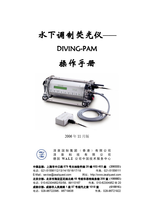
水下调制荧光仪——DIVING-PAM操作手册2006年11月版泽泉国际集团(香港)有限公司 泽 泉 科 技 有 限 公 司 德国WA L Z 公司中国技术服务中心中国总部:上海市中江路879号天地软件园28幢402-403座 (200333)电话:021-********/13/14/15/16/17/18 传真:021-********E-Mail :sevice@ 网址:北京分部:北京市海淀区花园北路48号院华思特商务楼209室(100083)电话:010-********/53/58,89110167 传真:010-********转20成都分部:成都市人民南路1段97号现代之窗1018室 (610016)电话:028-********,86719836 传真:028-********目录1 安全指导...................................................................................................................................- 4 -1.1 一般安全指导................................................................................................................- 4 -1.2 特殊安全指导................................................................................................................- 4 -2 光合作用与叶绿素荧光原理....................................................................................................- 5 -2.1 光合作用基本过程........................................................................................................- 5 -2.2 活体叶绿素荧光..........................................................................................................- 7 -2.2.1 叶绿素荧光的产生............................................................................................- 7 -2.2.2 叶绿素荧光诱导曲线........................................................................................- 8 -2.2.3 调制叶绿素荧光的测量....................................................................................- 8 -2.2.4 光响应曲线和快速光曲线..............................................................................- 10 -2.2.5 叶绿素荧光的暗弛豫......................................................................................- 10 -2.2.6 调制叶绿素荧光成像......................................................................................- 11 -3 DIVING-PAM简介..................................................................................................................- 12 -4 常用荧光参数.........................................................................................................................- 13 -4.1 Fo、Fm和Fv/Fm.........................................................................................................- 13 -4.3 Fm’.................................................................................................................................- 13 -4.3 Ft....................................................................................................................................- 13 -4.4 量子产量Yield.............................................................................................................- 13 -4.5 ETR和PAR..................................................................................................................- 14 -4.6 qP、qN和NPQ............................................................................................................- 14 -5 基础操作步骤.........................................................................................................................- 16 -6 按键操作.................................................................................................................................- 17 -6.1 单键操作......................................................................................................................- 17 -6.2 双键操作......................................................................................................................- 18 -7 数据存储功能.........................................................................................................................- 19 -8 MODE菜单介绍......................................................................................................................- 20 -8.1 MODE界面列表...........................................................................................................- 20 -8.2 MODE界面功能介绍...................................................................................................- 21 -9 DIVING-PAM的组成..............................................................................................................- 28 -9.1 主控单元......................................................................................................................- 28 -9.1.1 荧光的激发与检测............................................................................................- 28 -9.1.2 内置卤素灯.......................................................................................................- 29 -9.1.3 可充电电池.......................................................................................................- 29 -9.1.4 显示器...............................................................................................................- 30 -9.1.5 电子元件...........................................................................................................- 30 -9.1.6 接口介绍...........................................................................................................- 30 -9.2 标准光纤DIVING-PAM/F和微光纤DIVING-PAM/F1...........................................- 32 -9.3 光量子传感器..............................................................................................................- 32 -9.4 深度传感器..................................................................................................................- 33 -9.5 水温传感器..................................................................................................................- 33 -9.6 水下通用样品架DIVING-USH..................................................................................- 33 -9.6.1 介绍...................................................................................................................- 33 -9.6.2 应用方法:叶片状样品....................................................................................- 35 -9.6.3 应用方法:珊瑚、附着藻类等样品................................................................- 36 -9.6.4 应用方法:暗适应后测量Fv/Fm....................................................................- 37 -9.6.5 应用方法:测量叶片状样品吸收到的PAR...................................................- 38 -9.6.6 DIVING-USH的详细配件................................................................................- 39 -9.7 特殊叶夹/样品室.......................................................................................................- 40 -9.7.1 暗适应叶夹DIVING-LC................................................................................- 40 -9.7.2 表面样品室DIVING-SH(适合于珊瑚等0.................................................- 40 -9.7.3 磁性样品架DIVING-MLC(可选).............................................................- 40 -10 数据传输...............................................................................................................................- 42 -11 通过PC终端控制DIVING-PAM........................................................................................- 43 -12 维护.......................................................................................................................................- 44 -12.1 内置电池的更换......................................................................................................- 44 -12.2 卤素灯的更换..........................................................................................................- 46 -12.3 EPROM的更换........................................................................................................- 47 -12.4 保险丝的更换..........................................................................................................- 47 -12.5 清洁..........................................................................................................................- 47 - 附录1 技术参数......................................................................................................................- 48 - 附录2 警告和错误列表..........................................................................................................- 50 - 附录3 PIN分配.......................................................................................................................- 51 - 附录4 PC终端控制DIVING-PAM的命令列表...................................................................- 52 - 附录5 部分荧光基础理论文献...............................................................................................- 55 - 附录6 部分利用DIVING-PAM发表的文献.........................................................................- 59 -1 安全指导1.1 一般安全指导为避免触电,请不要拆开DIVING-PAM的主机。

August 2006Rev. 131/47L7800 seriesPositive voltage regulatorsFeature summary■Output current to 1.5A■Output voltages of 5; 5.2; 6; 8; 8.5; 9; 10; 12; 15; 18; 24V■Thermal overload protection ■Short circuit protection■Output transition SOA protectionDescriptionThe L7800 series of three-terminal positiveregulators is available in TO-220, TO-220FP , TO-3 and D 2PAK packages and several fixed output voltages, making it useful in a wide range of applications. These regulators can provide local on-card regulation, eliminating the distribution problems associated with single point regulation. Each type employs internal current limiting, thermal shut-down and safe area protection, making it essentially indestructible. If adequate heat sinking is provided, they can deliver over 1A output current. Although designedprimarily as fixed voltage regulators, thesedevices can be used with external components to obtain adjustable voltage and currents.Schematic diagramL7800 series2/47Contents1Pin configuration . . . . . . . . . . . . . . . . . . . . . . . . . . . . . . . . . . . . . . . . . . . 3 2Maximum ratings . . . . . . . . . . . . . . . . . . . . . . . . . . . . . . . . . . . . . . . . . . . . 4 3Test circuits . . . . . . . . . . . . . . . . . . . . . . . . . . . . . . . . . . . . . . . . . . . . . . . 5 4Electrical characteristics . . . . . . . . . . . . . . . . . . . . . . . . . . . . . . . . . . . . . 6 5Typical performance . . . . . . . . . . . . . . . . . . . . . . . . . . . . . . . . . . . . . . . . 26 6Package mechanical data . . . . . . . . . . . . . . . . . . . . . . . . . . . . . . . . . . . . 36 7Order code . . . . . . . . . . . . . . . . . . . . . . . . . . . . . . . . . . . . . . . . . . . . . . . 46 8Revision history . . . . . . . . . . . . . . . . . . . . . . . . . . . . . . . . . . . . . . . . . . . 47L7800 series Pin configuration 1 Pin configurationMaximum ratings L7800 series4/472 Maximum ratingsNote:Absolute Maximum Ratings are those values beyond which damage to the device mayoccur. Functional operation under these condition is not impliedTable 1.Absolute maximum ratingsSymbol ParameterValue Unit V I DC Input voltage for V O = 5 to 18V 35Vfor V O = 20, 24V40I O Output current Internally Limited P D Power dissipationInternally LimitedT STG Storage temperature range-65 to 150°C T OPOperating junction temperature rangefor L7800-55 to 150°C for L7800C0 to 150Table 2.Thermal DataSymbol ParameterD 2PAK TO-220TO-220FPTO-3Unit R thJC Thermal resistance junction-case 3554°C/W R thJAThermal resistance junction-ambient62.5506035°C/WL7800 series Test circuits 3 Test circuits5/47Electrical characteristics L7800 series6/474Electrical characteristicsTable 3.Electrical characteristics of L7805 (refer to the test circuits, T J = -55 to 150°C, V I = 10V, I O = 500 mA, C I = 0.33 µF , C O = 0.1 µF unless otherwise specified)Symbol ParameterTest conditionsMin.Typ.Max.Unit V O Output voltage T J = 25°C4.855.2V V O Output voltage I O = 5mA to 1A, P O ≤ 15W V I = 8 to 20V4.655 5.35V ∆V O (1)1.Load and line regulation are specified at constant junction temperature. Changes in V O due to heating effects must betaken into account separately. Pulse testing with low duty cycle is used.Line regulationV I = 7 to 25V , T J = 25°C 350mVV I = 8 to 12V , T J = 25°C 125∆V O (1)Load regulation I O = 5 mA to 1.5A, T J = 25°C 100mV I O = 250 to 750mA, T J = 25°C 25I d Quiescent current T J = 25°C 6mA ∆I d Quiescent current change I O = 5mA to 1A 0.5mA V I = 8 to 25 V 0.8∆V O /∆T Output voltage drift I O = 5mA0.6mV/°C eN Output noise voltage B =10Hz to 100KHz, T J = 25°C 40µV/V O SVR Supply voltage rejection V I = 8 to 18V , f = 120Hz 68dB V d Dropout voltage I O = 1A, T J = 25°C 2 2.5V R O Output resistance f = 1 KHz17m ΩI sc Short circuit current V I = 35V , T J = 25°C 0.75 1.2A I scpShort circuit peak currentT J = 25°C1.32.23.3AL7800 series Electrical characteristics7/47Table 4.Electrical characteristics of L7806 (refer to the test circuits, T J = -55 to 150°C, V I = 11V, I O = 500 mA, C I = 0.33 µF , C O = 0.1 µF unless otherwise specified)Symbol ParameterTest conditionsMin.Typ.Max.Unit V O Output voltage T J = 25°C5.7566.25V V O Output voltage I O = 5mA to 1A, P O ≤ 15W V I = 9 to 21V5.6566.35V ∆V O (1)Line regulationV I = 8 to 25V , T J = 25°C 60mVV I = 9 to 13V , T J = 25°C 30∆V O (1)Load regulation I O = 5 mA to 1.5A, T J = 25°C 100mV I O = 250 to 750mA, T J = 25°C 30I d Quiescent current T J = 25°C 6mA ∆I d Quiescent current change I O = 5mA to 1A 0.5mA V I = 9 to 25V 0.8∆V O /∆T Output voltage drift I O = 5mA0.7mV/°C eN Output noise voltage B =10Hz to 100KHz, T J = 25°C 40µV/V O SVR Supply voltage rejection V I = 9 to 19V , f = 120Hz 65dB V d Dropout voltage I O = 1A, T J = 25°C 2 2.5V R O Output resistance f = 1 KHz19m ΩI sc Short circuit current V I = 35V , T J = 25°C 0.75 1.2A I scpShort circuit peak currentT J = 25°C1.32.23.3A1.Load and line regulation are specified at constant junction temperature. Changes in V O due to heating effects must betaken into account separately. Pulse testing with low duty cycle is used.Electrical characteristics L7800 series8/47Table 5.Electrical characteristics of L7808 (refer to the test circuits, T J = -55 to 150°C, V I = 14V, I O = 500 mA, C I = 0.33 µF , C O = 0.1 µF unless otherwise specified)Symbol ParameterTest conditionsMin.Typ.Max.Unit V O Output voltage T J = 25°C7.788.3V V O Output voltage I O = 5mA to 1A, P O ≤ 15W V I = 11.5 to 23V7.688.4V ∆V O (1)Line regulationV I = 10.5 to 25V , T J = 25°C 80mVV I = 11 to 17V , T J = 25°C 40∆V O (1)Load regulation I O = 5 mA to 1.5A, T J = 25°C 100mV I O = 250 to 750mA, T J = 25°C 40I d Quiescent current T J = 25°C 6mA ∆I d Quiescent current change I O = 5mA to 1A 0.5mA V I = 11.5 to 25V 0.8∆V O /∆T Output voltage drift I O = 5mA1mV/°C eN Output noise voltage B =10Hz to 100KHz, T J = 25°C 40µV/V O SVR Supply voltage rejection V I = 11.5 to 21.5V , f = 120Hz 62dB V d Dropout voltage I O = 1A, T J = 25°C 2 2.5V R O Output resistance f = 1 KHz16m ΩI sc Short circuit current V I = 35V , T J = 25°C 0.75 1.2A I scpShort circuit peak currentT J = 25°C1.32.23.3A1.Load and line regulation are specified at constant junction temperature. Changes in V O due to heating effects must betaken into account separately. Pulse testing with low duty cycle is used.L7800 series Electrical characteristics9/47Table 6.Electrical characteristics of L7812 (refer to the test circuits, T J = -55 to 150°C, V I = 19V, I O = 500 mA, C I = 0.33 µF , C O = 0.1 µF unless otherwise specified)Symbol ParameterTest conditionsMin.Typ.Max.Unit V O Output voltage T J = 25°C11.51212.5V V O Output voltage I O = 5mA to 1A, P O ≤ 15W V I = 15.5 to 27V11.41212.6V ∆V O (1)Line regulationV I = 14.5 to 30V , T J = 25°C 120mVV I = 16 to 22V , T J = 25°C 60∆V O (1)Load regulation I O = 5 mA to 1.5A, T J = 25°C 100mV I O = 250 to 750mA, T J = 25°C 60I d Quiescent current T J = 25°C 6mA ∆I d Quiescent current change I O = 5mA to 1A 0.5mA V I = 15 to 30V 0.8∆V O /∆T Output voltage drift I O = 5mA1.5mV/°C eN Output noise voltage B =10Hz to 100KHz, T J = 25°C 40µV/V O SVR Supply voltage rejection V I = 15 to 25V , f = 120Hz 61dB V d Dropout voltage I O = 1A, T J = 25°C 2 2.5V R O Output resistance f = 1 KHz18m ΩI sc Short circuit current V I = 35V , T J = 25°C 0.75 1.2A I scpShort circuit peak currentT J = 25°C1.32.23.3A1.Load and line regulation are specified at constant junction temperature. Changes in V O due to heating effects must betaken into account separately. Pulse testing with low duty cycle is used.Table 7.Electrical characteristics of L7815 (refer to the test circuits, T J = -55 to 150°C, V I = 23V, I O = 500 mA, C I = 0.33 µF, C O = 0.1 µF unless otherwise specified)Symbol Parameter Test conditions Min.Typ.Max.Unit V O Output voltage T J = 25°C14.41515.6VV O Output voltage I O = 5mA to 1A, P O≤15WV I = 18.5 to 30V14.251515.75V∆V O(1)Line regulation V I = 17.5 to 30V, T J = 25°C150mV V I = 20 to 26V, T J = 25°C75∆V O(1)Load regulation I O = 5 mA to 1.5A, T J = 25°C150mV I O = 250 to 750mA, T J = 25°C75I d Quiescent current T J = 25°C6mA∆I d Quiescent current change I O = 5mA to 1A0.5mA V I = 18.5 to 30V0.8∆V O/∆T Output voltage drift I O = 5mA 1.8mV/°C eN Output noise voltage B =10Hz to 100KHz, T J = 25°C40µV/V O SVR Supply voltage rejection V I = 18.5 to 28.5V, f = 120Hz60dB V d Dropout voltage I O = 1A, T J = 25°C2 2.5V R O Output resistance f = 1 KHz19mΩI sc Short circuit current V I = 35V, T J = 25°C0.75 1.2AI scp Short circuit peak current T J = 25°C 1.3 2.2 3.3A1.Load and line regulation are specified at constant junction temperature. Changes in V O due to heating effects must betaken into account separately. Pulse testing with low duty cycle is used.10/47Table 8.Electrical characteristics of L7818 (refer to the test circuits, T J = -55 to 150°C, V I = 26V, I O = 500 mA, C I = 0.33 µF, C O = 0.1 µF unless otherwise specified)Symbol Parameter Test conditions Min.Typ.Max.Unit V O Output voltage T J = 25°C17.31818.7VV O Output voltage I O = 5mA to 1A, P O≤ 15WV I = 22 to 33V17.11818.9V∆V O(1)Line regulation V I = 21 to 33V, T J = 25°C180mV V I = 24 to 30V, T J = 25°C90∆V O(1)Load regulation I O = 5 mA to 1.5A, T J = 25°C180mV I O = 250 to 750mA, T J = 25°C90I d Quiescent current T J = 25°C6mA∆I d Quiescent current change I O = 5mA to 1A0.5mA V I = 22 to 33V0.8∆V O/∆T Output voltage drift I O = 5mA 2.3mV/°C eN Output noise voltage B =10Hz to 100KHz, T J = 25°C40µV/V O SVR Supply voltage rejection V I = 22 to 32V, f = 120Hz59dB V d Dropout voltage I O = 1A, T J = 25°C2 2.5V R O Output resistance f = 1 KHz22mΩI sc Short circuit current V I = 35V, T J = 25°C0.75 1.2AI scp Short circuit peak current T J = 25°C 1.3 2.2 3.3A1.Load and line regulation are specified at constant junction temperature. Changes in V O due to heating effects must betaken into account separately. Pulse testing with low duty cycle is used.11/47Table 9.Electrical characteristics of L7820 (refer to the test circuits, T J = -55 to 150°C, V I = 28V, I O = 500 mA, C I = 0.33 µF, C O = 0.1 µF unless otherwise specified)Symbol Parameter Test conditions Min.Typ.Max.Unit V O Output voltage T J = 25°C19.22020.8VV O Output voltage I O = 5mA to 1A, P O≤15WV I = 24 to 35V192021V∆V O(1)Line regulation V I = 22.5 to 35V, T J = 25°C200mV V I = 26 to 32V, T J = 25°C100∆V O(1)Load regulation I O = 5 mA to 1.5A, T J = 25°C200mV I O = 250 to 750mA, T J = 25°C100I d Quiescent current T J = 25°C6mA∆I d Quiescent current change I O = 5mA to 1A0.5mA V I = 24 to 35V0.8∆V O/∆T Output voltage drift I O = 5mA 2.5mV/°C eN Output noise voltage B =10Hz to 100KHz, T J = 25°C40µV/V O SVR Supply voltage rejection V I = 24 to 35V, f = 120Hz58dB V d Dropout voltage I O = 1A, T J = 25°C2 2.5V R O Output resistance f = 1 KHz24mΩI sc Short circuit current V I = 35V, T J = 25°C0.75 1.2AI scp Short circuit peak current T J = 25°C 1.3 2.2 3.3A1.Load and line regulation are specified at constant junction temperature. Changes in V O due to heating effects must betaken into account separately. Pulse testing with low duty cycle is used.12/47Table 10.Electrical characteristics of L7824 (refer to the test circuits, T J = -55 to 150°C, V I = 33V, I O = 500 mA, C I = 0.33 µF, C O = 0.1 µF unless otherwise specified)Symbol Parameter Test conditions Min.Typ.Max.Unit V O Output voltage T J = 25°C232425VV O Output voltage I O = 5mA to 1A, P O≤15WV I = 28 to 38V22.82425.2V∆V O(1)Line regulation V I = 27 to 38V, T J = 25°C240mV V I = 30 to 36V, T J = 25°C120∆V O(1)Load regulation I O = 5 mA to 1.5A, T J = 25°C240mV I O = 250 to 750mA, T J = 25°C120I d Quiescent current T J = 25°C6mA∆I d Quiescent current change I O = 5mA to 1A0.5mA V I = 28 to 38V0.8∆V O/∆T Output voltage drift I O = 5mA3mV/°C eN Output noise voltage B =10Hz to 100KHz, T J = 25°C40µV/V O SVR Supply voltage rejection V I = 28 to 38V, f = 120Hz56dB V d Dropout voltage I O = 1A, T J = 25°C2 2.5V R O Output resistance f = 1 KHz28mΩI sc Short circuit current V I = 35V, T J = 25°C0.75 1.2AI scp Short circuit peak current T J = 25°C 1.3 2.2 3.3A1.Load and line regulation are specified at constant junction temperature. Changes in V O due to heating effects must betaken into account separately. Pulse testing with low duty cycle is used.13/47Table 11.Electrical characteristics of L7805C (refer to the test circuits, T J = -55 to 150°C, V I = 10V,I O = 500 mA, C I = 0.33 µF, C O = 0.1 µF unless otherwise specified)Symbol Parameter Test conditions Min.Typ.Max.Unit V O Output voltage T J = 25°C 4.85 5.2VV O Output voltage I O = 5mA to 1A, P O≤15WV I = 7 to 20V4.7555.25V∆V O(1)Line regulation V I = 7 to 25V, T J = 25°C3100mV V I = 8 to 12V, T J = 25°C150∆V O(1)Load regulation I O = 5 mA to 1.5A, T J = 25°C100mV I O = 250 to 750mA, T J = 25°C50I d Quiescent current T J = 25°C8mA∆I d Quiescent current change I O = 5mA to 1A0.5mA V I = 7 to 25 V0.8∆V O/∆T Output voltage drift I O = 5mA-1.1mV/°C eN Output noise voltage B =10Hz to 100KHz, T J = 25°C40µV/V O SVR Supply voltage rejection V I = 8 to 18V, f = 120Hz62dB V d Dropout voltage I O = 1A, T J = 25°C2V R O Output resistance f = 1 KHz17mΩI sc Short circuit current V I = 35V, T J = 25°C0.75AI scp Short circuit peak current T J = 25°C 2.2A1.Load and line regulation are specified at constant junction temperature. Changes in V O due to heating effects must betaken into account separately. Pulse testing with low duty cycle is used.14/47Table 12.Electrical characteristics of L7852C (refer to the test circuits, T J = -55 to 150°C, V I = 10V,I O = 500 mA, C I = 0.33 µF, C O = 0.1 µF unless otherwise specified)Symbol Parameter Test conditions Min.Typ.Max.Unit V O Output voltage T J = 25°C 5.0 5.2 5.4VV O Output voltage I O = 5mA to 1A, P O≤15WV I = 8 to 20V4.955.2 5.45V∆V O(1)Line regulation V I = 7 to 25V, T J = 25°C3105mV V I = 8 to 12V, T J = 25°C152∆V O(1)Load regulation I O = 5 mA to 1.5A, T J = 25°C105mV I O = 250 to 750mA, T J = 25°C52I d Quiescent current T J = 25°C8mA∆I d Quiescent current change I O = 5mA to 1A0.5mA V I = 7 to 25 V 1.3∆V O/∆T Output voltage drift I O = 5mA-1mV/°C eN Output noise voltage B =10Hz to 100KHz, T J = 25°C42µV/V O SVR Supply voltage rejection V I = 8 to 18V, f = 120Hz61dB V d Dropout voltage I O = 1A, T J = 25°C2V R O Output resistance f = 1 KHz17mΩI sc Short circuit current V I = 35V, T J = 25°C0.75AI scp Short circuit peak current T J = 25°C 2.2A1.Load and line regulation are specified at constant junction temperature. Changes in V O due to heating effects must betaken into account separately. Pulse testing with low duty cycle is used.15/47Table 13.Electrical characteristics of L7806C (refer to the test circuits, T J = -55 to 150°C, V I = 11V,I O = 500 mA, C I = 0.33 µF, C O = 0.1 µF unless otherwise specified)Symbol Parameter Test conditions Min.Typ.Max.Unit V O Output voltage T J = 25°C 5.756 6.25VV O Output voltage I O = 5mA to 1A, P O≤15WV I = 8 to 21V5.766.3V∆V O(1)Line regulation V I = 8 to 25V, T J = 25°C120mV V I = 9 to 13V, T J = 25°C60∆V O(1)Load regulation I O = 5 mA to 1.5A, T J = 25°C120mV I O = 250 to 750mA, T J = 25°C60I d Quiescent current T J = 25°C8mA∆I d Quiescent current change I O = 5mA to 1A0.5mA V I = 8 to 25V 1.3∆V O/∆T Output voltage drift I O = 5mA-0.8mV/°C eN Output noise voltage B =10Hz to 100KHz, T J = 25°C45µV/V O SVR Supply voltage rejection V I = 9 to 19V, f = 120Hz59dB V d Dropout voltage I O = 1A, T J = 25°C2V R O Output resistance f = 1 KHz19mΩI sc Short circuit current V I = 35V, T J = 25°C0.55AI scp Short circuit peak current T J = 25°C 2.2A1.Load and line regulation are specified at constant junction temperature. Changes in V O due to heating effects must betaken into account separately. Pulse testing with low duty cycle is used.16/47Table 14.Electrical characteristics of L7808C (refer to the test circuits, T J = -55 to 150°C, V I = 14V,I O = 500 mA, C I = 0.33 µF, C O = 0.1 µF unless otherwise specified)Symbol Parameter Test conditions Min.Typ.Max.Unit V O Output voltage T J = 25°C7.788.3VV O Output voltage I O = 5mA to 1A, P O≤15WV I = 10.5 to 25V7.688.4V∆V O(1)Line regulation V I = 10.5 to 25V, T J = 25°C160mV V I = 11 to 17V, T J = 25°C80∆V O(1)Load regulation I O = 5 mA to 1.5A, T J = 25°C160mV I O = 250 to 750mA, T J = 25°C80I d Quiescent current T J = 25°C8mA∆I d Quiescent current change I O = 5mA to 1A0.5mA V I = 10.5 to 25V1∆V O/∆T Output voltage drift I O = 5mA-0.8mV/°C eN Output noise voltage B =10Hz to 100KHz, T J = 25°C52µV/V O SVR Supply voltage rejection V I = 11.5 to 21.5V, f = 120Hz56dB V d Dropout voltage I O = 1A, T J = 25°C2V R O Output resistance f = 1 KHz16mΩI sc Short circuit current V I = 35V, T J = 25°C0.45AI scp Short circuit peak current T J = 25°C 2.2A1.Load and line regulation are specified at constant junction temperature. Changes in V O due to heating effects must betaken into account separately. Pulse testing with low duty cycle is used.17/47Table 15.Electrical characteristics of L7885C (refer to the test circuits, T J = -55 to 150°C, V I =14.5V, I O = 500 mA, C I = 0.33 µF, C O = 0.1 µF unless otherwise specified)Symbol Parameter Test conditions Min.Typ.Max.Unit V O Output voltage T J = 25°C8.28.58.8VV O Output voltage I O = 5mA to 1A, P O≤15WV I = 11 to 26V8.18.58.9V∆V O(1)Line regulation V I = 11 to 27V, T J = 25°C160mV V I = 11.5 to 17.5V, T J = 25°C80∆V O(1)Load regulation I O = 5 mA to 1.5A, T J = 25°C160mV I O = 250 to 750mA, T J = 25°C80I d Quiescent current T J = 25°C8mA∆I d Quiescent current change I O = 5mA to 1A0.5mA V I = 11 to 27V1∆V O/∆T Output voltage drift I O = 5mA-0.8mV/°C eN Output noise voltage B =10Hz to 100KHz, T J = 25°C55µV/V O SVR Supply voltage rejection V I = 12 to 22V, f = 120Hz56dB V d Dropout voltage I O = 1A, T J = 25°C2V R O Output resistance f = 1 KHz16mΩI sc Short circuit current V I = 35V, T J = 25°C0.45AI scp Short circuit peak current T J = 25°C 2.2A1.Load and line regulation are specified at constant junction temperature. Changes in V O due to heating effects must betaken into account separately. Pulse testing with low duty cycle is used.18/47Table 16.Electrical characteristics of L7809C (refer to the test circuits, T J = -55 to 150°C, V I = 15V,I O = 500 mA, C I = 0.33 µF, C O = 0.1 µF unless otherwise specified)Symbol Parameter Test conditions Min.Typ.Max.Unit V O Output voltage T J = 25°C8.6499.36VV O Output voltage I O = 5mA to 1A, P O≤ 15WV I = 11.5 to 26V8.5599.45V∆V O(1)Line regulation V I = 11.5 to 26V, T J = 25°C180mV V I = 12 to 18V, T J = 25°C90∆V O(1)Load regulation I O = 5 mA to 1.5A, T J = 25°C180mV I O = 250 to 750mA, T J = 25°C90I d Quiescent current T J = 25°C8mA∆I d Quiescent current change I O = 5mA to 1A0.5mA V I = 11.5 to 26V1∆V O/∆T Output voltage drift I O = 5mA-1mV/°C eN Output noise voltage B =10Hz to 100KHz, T J = 25°C70µV/V O SVR Supply voltage rejection V I = 12 to 23V, f = 120Hz55dB V d Dropout voltage I O = 1A, T J = 25°C2V R O Output resistance f = 1 KHz17mΩI sc Short circuit current V I = 35V, T J = 25°C0.40AI scp Short circuit peak current T J = 25°C 2.2A1.Load and line regulation are specified at constant junction temperature. Changes in V O due to heating effects must betaken into account separately. Pulse testing with low duty cycle is used.19/47Electrical characteristics L7800 series20/47Table 17.Electrical characteristics of L7810C (refer to the test circuits, T J = -55 to 150°C, V I = 15V , I O = 500 mA, C I = 0.33 µF , C O = 0.1 µF unless otherwise specified)Symbol ParameterTest conditionsMin.Typ.Max.Unit V O Output voltage T J = 25°C9.61010.4V V O Output voltage I O = 5mA to 1A, P O ≤ 15W V I = 12.5 to 26V9.51010.5V ∆V O (1)Line regulationV I = 12.5 to 26V , T J = 25°C 200mVV I = 13.5 to 19V , T J = 25°C 100∆V O (1)Load regulation I O = 5 mA to 1.5A, T J = 25°C 200mV I O = 250 to 750mA, T J = 25°C 100I d Quiescent current T J = 25°C 8mA ∆I d Quiescent current change I O = 5mA to 1A 0.5mA V I = 12.5 to 26V 1∆V O /∆T Output voltage drift I O = 5mA-1mV/°C eN Output noise voltage B =10Hz to 100KHz, T J = 25°C 70µV/V O SVR Supply voltage rejection V I = 13 to 23V , f = 120Hz 55dB V d Dropout voltage I O = 1A, T J = 25°C 2V R O Output resistance f = 1 KHz17m ΩI sc Short circuit current V I = 35V , T J = 25°C 0.40A I scpShort circuit peak currentT J = 25°C2.2A1.Load and line regulation are specified at constant junction temperature. Changes in V O due to heating effects must betaken into account separately. Pulse testing with low duty cycle is used.L7800 series Electrical characteristics21/47Table 18.Electrical characteristics of L7812C (refer to the test circuits, T J = -55 to 150°C, V I = 19V , I O = 500 mA, C I = 0.33 µF , C O = 0.1 µF unless otherwise specified)Symbol ParameterTest conditionsMin.Typ.Max.Unit V O Output voltage T J = 25°C11.51212.5V V O Output voltage I O = 5mA to 1A, P O ≤ 15W V I = 14.5 to 27V11.41212.6V ∆V O (1)Line regulationV I = 14.5 to 30V , T J = 25°C 240mVV I = 16 to 22V , T J = 25°C 120∆V O (1)Load regulation I O = 5 mA to 1.5A, T J = 25°C 240mV I O = 250 to 750mA, T J = 25°C 120I d Quiescent current T J = 25°C 8mA ∆I d Quiescent current change I O = 5mA to 1A 0.5mA V I = 14.5 to 30V 1∆V O /∆T Output voltage drift I O = 5mA-1mV/°C eN Output noise voltage B =10Hz to 100KHz, T J = 25°C 75µV/V O SVR Supply voltage rejection V I = 15 to 25V , f = 120Hz 55dB V d Dropout voltage I O = 1A, T J = 25°C 2V R O Output resistance f = 1 KHz18m ΩI sc Short circuit current V I = 35V , T J = 25°C 0.35A I scpShort circuit peak currentT J = 25°C2.2A1.Load and line regulation are specified at constant junction temperature. Changes in V O due to heating effects must betaken into account separately. Pulse testing with low duty cycle is used.Electrical characteristics L7800 series22/47Table 19.Electrical characteristics of L7815C (refer to the test circuits, T J = -55 to 150°C, V I = 23V , I O = 500 mA, C I = 0.33 µF , C O = 0.1 µF unless otherwise specified)Symbol ParameterTest conditionsMin.Typ.Max.Unit V O Output voltage T J = 25°C14.51515.6V V O Output voltage I O = 5mA to 1A, P O ≤ 15W V I = 17.5 to 30V14.251515.75V ∆V O (1)Line regulationV I = 17.5 to 30V , T J = 25°C 300mVV I = 20 to 26V , T J = 25°C 150∆V O (1)Load regulation I O = 5 mA to 1.5A, T J = 25°C 300mV I O = 250 to 750mA, T J = 25°C 150I d Quiescent current T J = 25°C 8mA ∆I d Quiescent current change I O = 5mA to 1A 0.5mA V I = 17.5 to 30V 1∆V O /∆T Output voltage drift I O = 5mA-1mV/°C eN Output noise voltage B =10Hz to 100KHz, T J = 25°C 90µV/V O SVR Supply voltage rejection V I = 18.5 to 28.5V , f = 120Hz 54dB V d Dropout voltage I O = 1A, T J = 25°C 2V R O Output resistance f = 1 KHz19m ΩI sc Short circuit current V I = 35V , T J = 25°C 0.23A I scpShort circuit peak currentT J = 25°C2.2A1.Load and line regulation are specified at constant junction temperature. Changes in V O due to heating effects must betaken into account separately. Pulse testing with low duty cycle is used.L7800 series Electrical characteristics23/47Table 20.Electrical characteristics of L7818C (refer to the test circuits, T J = -55 to 150°C, V I = 26V , I O = 500 mA, C I = 0.33 µF , C O = 0.1 µF unless otherwise specified)Symbol ParameterTest conditionsMin.Typ.Max.Unit V O Output voltage T J = 25°C17.31818.7V V O Output voltage I O = 5mA to 1A, P O ≤ 15W V I = 21 to 33V17.11818.9V ∆V O (1)Line regulationV I = 21 to 33V , T J = 25°C 360mVV I = 24 to 30V , T J = 25°C 180∆V O (1)Load regulation I O = 5 mA to 1.5A, T J = 25°C 360mV I O = 250 to 750mA, T J = 25°C 180I d Quiescent current T J = 25°C 8mA ∆I d Quiescent current change I O = 5mA to 1A 0.5mA V I = 21 to 33V 1∆V O /∆T Output voltage drift I O = 5mA-1mV/°C eN Output noise voltage B =10Hz to 100KHz, T J = 25°C 110µV/V O SVR Supply voltage rejection V I = 22 to 32V , f = 120Hz 53dB V d Dropout voltage I O = 1A, T J = 25°C 2V R O Output resistance f = 1 KHz22m ΩI sc Short circuit current V I = 35V , T J = 25°C 0.20A I scpShort circuit peak currentT J = 25°C2.1A1.Load and line regulation are specified at constant junction temperature. Changes in V O due to heating effects must betaken into account separately. Pulse testing with low duty cycle is used.Electrical characteristics L7800 series24/47Table 21.Electrical characteristics of L7820C (refer to the test circuits, T J = -55 to 150°C, V I = 28V , I O = 500 mA, C I = 0.33 µF , C O = 0.1 µF unless otherwise specified)Symbol ParameterTest conditionsMin.Typ.Max.Unit V O Output voltage T J = 25°C19.22020.8V V O Output voltage I O = 5mA to 1A, P O ≤ 15W V I = 23 to 35V192021V ∆V O (1)Line regulationV I = 22.5 to 35V , T J = 25°C 400mVV I = 26 to 32V , T J = 25°C 200∆V O (1)Load regulation I O = 5 mA to 1.5A, T J = 25°C 400mV I O = 250 to 750mA, T J = 25°C 200I d Quiescent current T J = 25°C 8mA ∆I d Quiescent current change I O = 5mA to 1A 0.5mA V I = 23 to 35V 1∆V O /∆T Output voltage drift I O = 5mA-1mV/°C eN Output noise voltage B =10Hz to 100KHz, T J = 25°C 150µV/V O SVR Supply voltage rejection V I = 24 to 35V , f = 120Hz 52dB V d Dropout voltage I O = 1A, T J = 25°C 2V R O Output resistance f = 1 KHz24m ΩI sc Short circuit current V I = 35V , T J = 25°C 0.18A I scpShort circuit peak currentT J = 25°C2.1A1.Load and line regulation are specified at constant junction temperature. Changes in V O due to heating effects must betaken into account separately. Pulse testing with low duty cycle is used.。

The following quick steps will guide you through testing the absolute bare minimum essentials of your motherboard before installing it into a system chassis. Visual aids are provided to assist you during the following procedures.To reduce the risk of fire, electric shock, and injury always follow basic safety precautions. It is recommended that you use electrostatic discharge (ESD) countermeasures such as an ESD wrist strap or anti-static mat when handling computer components.After removing the EVGA nForce 780i SLI FTW from its packaging, place it on to a nonconductive surface. For example: wood, cardboard box, or an anti-static mat.EVGA nForce 780i SLI FTW Visual Guidec.c.Apply a small, pea-sized drop of thermal paste on to the middle of the processor. Install your processor heatsink and fan.6On the power supply, flip the power switch to theON position. LEDs will now be lit on the motherboard. Press the onboard Clear CMOS button once then press the green Power Button to begin powering up the system.At this final stage, you should now be greeted with the POST screen on your monitor.9Power Button8Insert your graphics card into either the PCI-E 2.0 slot or the PCI slot. The type of slot depends on the graphic cardEVGA nForce 780i SLI FTW Quick Install GuideSTEP 1 - Install CPUThank you for purchasing an EVGA product.Please remember to register your product at:/registerFor the latest drivers and updates for yourproduct please visit:/support/driversTo visit and search our knowledge base andproduct FAQ please visit:/FAQTo visit the EVGA community messageboards please visit:/forums1. Unlock the socket by pressingthe lever sideways, then lift it upto a 90o angle.2. Lift the load plate. There isa protective socket cover on theload plate to protect the socketwhen there is no CPU installed.3. Remove the protective socketcover from the load plate.(Save this protective piece,as it is needed whenevertransporting or shipping themotherboard.)4. Align the notches in the CPUwith the notches on the socket.5. Lower the CPU straight intothe socket. Close the lid plateand engage the socket lever.6. The CPU will need a propercooling solution, please referto the manual that came withyour heatsink for detailedinstructions.STEP 2 - InstallMemorySTEP 3 - InstallGraphics Card(s)FloppySATAIDE8 pin 12v power1. This motherboard has threePCI Express X16 slots. If youare installing a single graphicscard use the PCI-E slot closestto the CPU socket.(Three)PCI Express X16 slots.STEP 4 - ConnectPeripheralsCablesSTEP 5 - Connectpower cablesSTEP 6 - ConnectHeadersFor more information about these services as well as ourterms and conditions please visitGaming ● Imaging ● 3D Video ● Entertainment ● Photos ● Graphics1. Now connect your peripheraldevices such as hard drives,floppy drive, and DVD-ROMdrives to the motherboard.1. Next you will connect powercables to the motherboard andany other peripherals in yoursystem.* Remember to plug in your6 or 8 pin PCI-E powercables to your graphicscard(s) if necessary.1. Connect the front panelheaders and any other headersthat are going to be in use.1. This motherboard supports upto four 240-pin memory modules.Having matched pairs is highlyrecommended for dual channelconfigurations.2. For dual channel configurationsuse DIMM slots 0 and 1, 2 and 3,or 0 through 3.* Use matching color slots fordual channelSupport Premium Servicesdvanced RMAStepping-Up Your Customer ServiceLimited Lifetime Warrantyupon product registration90 Day Step -U p ProgramE V G A A D V A N C E D G R A P H I C S T U N I N GEVGA Corp 2900 Saturn Street, Suite B Brea, CA 92821 *Not all Premium Services applyto all products.24/7*Tech Support888 . 881. EVGA714 . 528. 4500/support*24/7 North America onlyPWRLED PWRSW BlankHK_LED RESET NoConnect2+-1109。


LP78070规格书1. 引言LP78070是一款高性能的芯片,专为物联网设备设计。
本文档旨在提供LP78070的详细规格信息,以帮助开发人员了解该芯片的功能和技术特性。
2. 芯片概述LP78070是一款集成度高、功耗低的芯片,采用先进的制造工艺和架构设计。
它具有以下主要特点: - 高性能:LP78070采用先进的处理器和高速数据总线,能够实现快速的数据处理和传输。
- 低功耗:芯片通过优化电路设计和功耗管理机制,实现了低功耗运行模式,以延长设备电池寿命。
- 多功能:LP78070支持多种通信接口和传感器连接,可以适配各种物联网设备应用场景。
- 稳定性:芯片具有高可靠性和稳定性,能够在恶劣的环境条件下正常工作。
3. 技术规格3.1 处理器LP78070搭载一颗高性能的处理器,具有以下主要技术指标: - 主频:1GHz - 核心数量:双核 - 架构:ARM Cortex-A73.2 存储器LP78070内置存储器,包括闪存和内存,具体规格如下: - 闪存容量:8GB - 内存容量:1GB3.3 通信接口LP78070支持多种通信接口,以便与其他设备进行数据交换。
以下是主要的通信接口规格: - Wi-Fi:支持IEEE802.11b/g/n协议 - 蓝牙:支持蓝牙4.2版本 - 以太网:支持Ethernet 10/100Mbps3.4 传感器接口LP78070提供了多个传感器接口,可以方便地连接各种传感器设备。
以下是主要的传感器接口规格: - I2C接口:支持最大100kHz的传输速率 - SPI接口:支持最大50MHz的传输速率 - GPIO接口:提供多个通用输入/输出引脚3.5 电源管理LP78070具有灵活的电源管理功能,以实现低功耗运行和电池寿命延长。
以下是电源管理的一些主要技术指标: - 输入电压范围:3.3V-5V - 工作电流:最大100mA - 待机电流:最大10μA4. 应用领域LP78070广泛应用于物联网设备领域,适用于以下应用场景: - 智能家居:LP78070可以与各种家居设备连接,实现智能控制和远程监控功能。