1SE402-3;中文规格书,Datasheet资料
- 格式:pdf
- 大小:961.26 KB
- 文档页数:2


1FAAC S.p.A.Via Benini, 140069 Zola Predosa (BO) - ITALIATel.: 051/61724 - Fax: 051/758518www.faac.it732143 Rev.A.EC DECLARATION OF CONFORMITY FOR MACHINES ....................................................................................p. 2 WARNINGS FOR THE INSTALLER .......................................................................................................................p. 2 1.DESCRIPTION AND TECHNICAL SPECIFICATIONS ....................................................................................p. 31.1.DIMENSIONS ................................................................................................................................p. 32.ELECTRIC DEVICES (standard system) ....................................................................................................p. 33.INSTALLING THE AUTOMATED SYSTEM ......................................................................................................p. 43.1.PRELIMINARY CHECKS ................................................................................................................p. 43.2.INSTALLATION DIMENSIONS ........................................................................................................p. 43.2.1.GENERAL RULES FOR DETERMINING THE INSTALLATION DIMENSIONS ............................p. 43.3.INSTALLATION OF THE OPERATORS .............................................................................................p. 44.START-UP ....................................................................................................................................................p. 64.1.ADJUSTING THE ANTI-CRUSHING SYSTEM ..................................................................................p. 65.FINAL OPERATIONS ...................................................................................................................................p. 76.AUTOMATED SYSTEM TEST .........................................................................................................................p. 77.MANUAL OPERATION ...............................................................................................................................p. 78.RESTORING NORMAL OPERATION MODE ................................................................................................p. 79.MAINTENANCE ..........................................................................................................................................p. 710.REPAIRS .....................................................................................................................................................p. 711.TROUBLE SHOOTING .................................................................................................................................p. 821)ATTENTION! To ensure the safety of people, it is important that you readall the following instructions. Incorrect installation or incorrect use of the product could cause serious harm to people.2)Carefully read the instructions before beginning to install the product.3)Do not leave packing materials (plastic, polystyrene, etc.) within reachof children as such materials are potential sources of danger.4)Store these instructions for future reference.5)This product was designed and built strictly for the use indicated in thisdocumentation. Any other use, not expressly indicated here, could compromise the good condition/operation of the product and/or be a source of danger.6)FAAC declines all liability caused by improper use or use other than thatfor which the automated system was intended.7)Do not install the equipment in an explosive atmosphere: the presenceof inflammable gas or fumes is a serious danger to safety.8)The mechanical parts must conform to the provisions of Standards EN12604 and EN 12605.For non-EU countries, to obtain an adequate level of safety, the Standards mentioned above must be observed, in addition to national legal regulations.9)FAAC is not responsible for failure to observe Good Technique in theconstruction of the closing elements to be motorised, or for any deformation that may occur during use.10)The installation must conform to Standards EN 12453 and EN 12445.For non-EU countries, to obtain an adequate level of safety, the Standards mentioned above must be observed, in addition to national legal regulations.11)Before attempting any job on the system, cut out electrical power .12)The mains power supply of the automated system must be fitted with anall-pole switch with contact opening distance of 3mm or greater. Use of a 6A thermal breaker with all-pole circuit break is recommended.13)Make sure that a differential switch with threshold of 0.03 A is fittedupstream of the system.14)Make sure that the earthing system is perfectly constructed, andconnect metal parts of the means of the closure to it.15)The safety devices (EN 12978 standard) protect any danger areasagainst mechanical movement Risks , such as crushing, dragging,and shearing.16)Use of at least one indicator-light (e.g. FAACLIGHT ) is recommendedfor every system, as well as a warning sign adequately secured to the frame structure, in addition to the devices mentioned at point “15”.17)FAAC declines all liability as concerns safety and efficient operationof the automated system, if system components not produced by FAAC are used.18)For maintenance, strictly use original parts by FAAC.19)Do not in any way modify the components of the automated system.20)The installer shall supply all information concerning manual operationof the system in case of an emergency, and shall hand over to the user the warnings handbook supplied with the product.21)Do not allow children or adults to stay near the product while it isoperating.22)Keep remote controls or other pulse generators away from children,to prevent the automated system from being activated involuntarily.23)Transit through the leaves is allowed only when the gate is fully open.24)The user must not attempt any kind of repair or direct action whateverand contact qualified personnel only.25)Maintenance: check at least every 6 months the efficiency of thesystem, particularly the efficiency of the safety devices (including,where foreseen, the operator thrust force) and of the release devices.26)Anything not expressly specified in these instructions is not permitted.WARNINGS FOR THE INSTALLERGENERAL SAFETY OBLIGATIONSEC DECLARATION OF CONFORMITY FOR MACHINES(DIRECTIVE 98/37/EC)Manufacturer:FAAC S.p.A.Address:Via Benini, 1 - 40069 Zola Predosa BOLOGNA - ITALY Declares that:402 mod. operator,•is built to be integrated into a machine or to be assembled with other machinery to create a machine under the provisions of Directive 98/37/EC;•conforms to the essential safety requirements of the following EEC directives:73/23/EEC and subsequent amendment 93/68/EEC.89/336/EEC and subsequent amendment 92/31/EEC and 93/68/EECand also declares that it is prohibited to put into service the machinery until the machine in which it will be integrated or of which it will become a component has been identified and declared as conforming to the conditions of Directive 98/37/EC.Bologna, 01 January 2005The Managing DirectorA. Bassi3These instructions apply to the following models:402 CBC - 402 SBSThe FAAC 402 automated system for swing leaf gates consists of an enbloc composed of an electric pump and a hydraulic piston which transmits drive to the leaf.The model with a hydraulic locking does not require installation of electric locks, as it guarantees mechanical locking of the leaf when the motor is not operating.The model without a hydraulic locking, requires the installation of electric locks to ensure the leaf is mechanically locked.The 402 automated systems were designed and built to automate swing leaf gates. Do not use for any other purpose.Tab. 1: Technical specifications of “402 Operator”MODEL402 CBC402 SBSPower supply voltage 230 Vac(+6%-10%) 50 (6o) Hz Rod extension speed 1.3 cm/s 1 cm/s Pump flow rate1 l/min 0.75 l/min Traction and thrust force 0-500 daN0-690 daNOperating ambient temperature -40°C - +55°CAbsorbed power 220 W Absorbed current 1 A Motor rotation speed 1400 rpm Motor winding temperature 120°C Weight 6.5 kg Type of oil FAAC HP OILProtection class IP 55Single leaf max length 1,80 m3,00 mUse frequency55 (cycles/hour)4To ensure a correctly operating automated system, the structure of the existing gate or gate to be built must satisfy the following requirements:•Max length of leaves according to the dimensions of Table 1 on page 3.• A strong and rigid leaf structure.•Smooth, uniform leaves movement, without any irregular friction during the entire travel;•Existing hinges in good condition.•Travel limit mechanical stops must be provided.We advise you to carry out the metalwork jobs before installing the automated system.The condition of the structure directly influences the reliability and safety of the automated system.Table A : Recommended dimensions for standard operatorsc = The effective rod stroke is shorter than the maximum stroke, inorder to prevent the rod from reaching its stop point internally, during the opening and closing stages.(*) Rod effective stroke (**) maximum dimension1)Fasten the rear attachment on the pilaster, following the indications in Table A . Modify, if necessary, the length of the supplied attachment.Attention : To avoid compromising good operator functionality, we recommend you to respect the indicated dimensions.• For iron pilasters, accurately weld the rear attachment (ref.ባ, Fig. 6) directly on the pilaster.• For masonry pilasters, select one of the following solutions:A)appropriately lay a walling-in plate and then accurately weld the rear attachment.B)secure, with screws and expansion plugs, the rear attachment plate (ref. a, Fig.6) to the pilaster and then accurately weld the rear attachment to theplate as shown in Fig. 6.If the dimensions indicated in table A or B cannot be executed,the following must be considered in order to determine different measurements:-to obtain 90° opening of the leaf: a + b = c.-to obtain over 90° opening of the leaf: a + b < c.-lower a and b dimensions will result in higher speeds . We advise you to observe the current legal regulations;-limit the difference of the a and b dimensions to within 40 mm :higher differences will considerably vary speed during the opening and closing motion;-for reasons of operator dimensions, the minimum Z dimension is 50 mm (Fig. 4);-if the pilaster dimensions or the position of the hinge (dimension d ) do not make it possible to contain dimension a to the required size, a niche must be made in the pilaster as shown in Opening angle 90°110°a (mm)120100b (mm)120100c(*)(mm)240240d(**)(mm)705056-Lastly, remove the key and restore the power supply to the system.For any repairs, contact FAAC’s authorised Repair Centres.78The following table will help you identify and solve some particular conditions.CONDITIONGate not moving.Gate moving slowly.Gate moving jogwise.The operator is losing oil from the breather screw.The leaves stop at slow-down.Gate speed not constant.A B CD E FSUGGESTION-Check if mains power is supplied.-Make sure that the operator is not unlocked. (chapter 8.).-Check the adjustment of the anti-crushing system (paragraph 4.1).-Check oil level inside the tank. (chapter 9 - Fig. 16).-Check the connection and operation of the thrust capacitor.-Check the efficiency of the electronic control unit.-Check the adjustment of the anti-crushing system (paragraph 4.1).-Make sure that you have removed the breather screw (chapter 5).-Run some complete gate opening and closing cycles, in order to release any air inside the piston.-An initial, minimum oil leak is normal. A larger leak may occur if the operator is not fitted in a perfectly horizontal plane. If the oil leak does not stop soon, weadvise you to visit an authorised repair centre.-Check the adjustment of the anti-crushing system (paragraph 4.1).-Incorrect installation dimensions (paragraph 3.2).Notes919M A I N T E N A N C E R E G I S T E R.o N e t a D b o j f o n o i t p i r c s e D se r u t a n g i S 1_______________________________________________________________________________________________________________________________________na i c i n h c e T re m o t s u C 2_______________________________________________________________________________________________________________________________________na i c i n h c e T re m o t s u C 3_______________________________________________________________________________________________________________________________________na i c i n h c e T re m o t s u C 4_______________________________________________________________________________________________________________________________________na i c i n h c e T re m o t s u C 5_______________________________________________________________________________________________________________________________________na i c i n h c e T re m o t s u C 6_______________________________________________________________________________________________________________________________________na i c i n h c e T re m o t s u C 7_______________________________________________________________________________________________________________________________________na i c i n h c e T re m o t s u C 8_______________________________________________________________________________________________________________________________________na i c i n h c e T re m o t s u C 9_______________________________________________________________________________________________________________________________________na i c i n h c e T re m o t s u C 01_______________________________________________________________________________________________________________________________________na i c i n h c e T re m o t s u C I n s t a l l a t i o n t e c h n i c i a n ________________________________________________C u s t o m e r ___________________________________________________________________T y p e of s y s t e m ________________________________________________________S e r i a l n u m b e r _________________________________________________________I n s t a l l a t i o n d a t e ______________________A c t i v a t i o n ________________________S y s t e m c o n f ig u r a t i o nT R A P L E D O M RE B M U N L A I R E S e r o t a u t t A 402C A A F 1e c i v e d y t e f a S 2e c i v e d y t ef a S 1s l l e c o t o h p f o r i a P 2s l l e c o t o h p f o r i a P 1e c i v e d l o r t n o C 2e c i v e d l o r t n o C lo r t n o c o i d a R pm a l g n i h s a l F ec i v ed re h t O ec i v ed re h t O I n d i c a t i o n of r e s i d u a l r i s k s a n d o f f o r e s e e a b l e i m p r o p e r u s e_________________________________________________________________________________________________________________________________________________________________________________________________________________________________________________________________________________________________________________________________________________________________________________________________________________________________________________________________________________________________________________________________________________________________________________________________________________________________________________________________________________________________________________________________________________________________________________________________________________________________________________________________________________________________________________________________________________________________Read the instructions carefully before using the product and store them for future useIf correctly installed and used, the 402 automated system ensures a high degree of safety.Some simple rules on behaviour can prevent accidental trouble:-Do not pass between the leaves when they are moving. Waitfor the leaves to open fully before passing through them.-Do not, on any account stay in between the leaves.-Do not stand near the automated system, and do not allowchildren, persons or things to do so, especially when it is operating.-Keep remote controls or other pulse generators away fromchildren, to prevent the automated system from being activated involuntarily.-Do not allow children to play with the automated system.-Do not willingly obstruct leaves movement.-Prevent any branches or shrubs from interfering with leavesmovement.-Keep indicator-lights efficient and easy to see.-Do not attempt to activate the leaves by hand unless you havereleased them.-In the event of malfunctions, release the leaves to allow accessand wait for qualified technical personnel to do the necessary work.-When you have set manual operation mode, cut power to thesystem before restoring normal operation.-Do not in any way modify the components of the automatedsystem.-Do not attempt any kind of repair of direct action whateverand contact qualified personnel only.-At least every six months: arrange a check by qualifiedpersonnel of the automated system, safety devices and earth connection.These instructions apply to the following models:402 CBC - 402 SBS.The FAAC 402 automated system for swing leaf gates consists of a hydraulic enbloc composed of an electric pump and a hydraulic piston which transmits drive to the leaf.The models with a hydraulic locking do not require installation of an electric lock, as they guarantee mechanical locking of the leaf when the motor is not operating.The other models, without a hydraulic locking always require one or more electric locks to ensure the leaf is mechanically locked.Leaves of up to 3 mt can be automated depending on the selected model.The functioning of the operators is controlled by an electronic control unit, housed in an enclosure with adequate degree of protection against atmosphere agents.The leaves are normally closed.When the electronic control unit receives an opening command from the radio control or any other pulse generator, it activates the hydraulic appliance which rotates the leaves until they reach the opening position to allow access.If automatic mode was set, the leaves close automatically after selected pause time has elapsed.If the semi-automatic mode was set, a second pulse must be sent to close the leaf again.A stop pulse (if supplied) always stops movement.For details on the behaviour of the automated system in different function logics, consult the installer.Automated systems include safety devices (photocells) that prevent the leaves from moving when there is an obstacle in the area they protect.The 402 automated system is supplied standard with a hydraulic anti-crush protection safety device (BY-PASS) which limits the torque transmitted to the leaves.The warning-light indicates the current leaf movement.If the gate has to be moved manually due to a power cut or fault of the automated system, use the release device as follows:-Insert the triangular key on the release screw located in the lower part of the flange (Fig.1).-Turn the release key anti-clockwise for about two turns.-Open or close the leaf manually.To prevent an involuntary pulse from activating the operator during the manoeuvre, cut power to the system before re-locking the operator.-To re-lock the operator, turn the key clockwise until it stops (Fig.1).-Release the operator from the front and rear attachments.732143 - Rev. A。

Product DescriptionOrdering InformationTypical ApplicationsFeaturesFunctional Block DiagramRF Micro Devices, Inc.7628 Thorndike Road Greensboro, NC 27409, USA Tel (336) 664 1233Fax (336) 664 0454 Optimum Technology Matching® AppliedSi BJTGaAs MESFET GaAs HBT Si Bi-CMOSSiGe HBT Si CMOS InGaP/HBTGaN HEMTSiGe Bi-CMOSPin 1GroundRF INGroundCASCADABLE BROADBANDGaAs MMIC AMPLIFIER DC TO 8GHz•Narrow and Broadband Commercial and Military Radio Designs•Linear and Saturated Amplifiers •Gain Stage or Driver Amplifiers for MWRadio/Optical Designs (PTP/PMP/LMDS/UNII/VSA T/WLAN/Cellular/DWDM)The NBB-402 cascadable broadband InGaP/GaAs MMIC amplifier is a low-cost, high-performance solution for gen-eral purpose RF and microwave amplification needs. This 50Ω gain block is based on a reliable HBT proprietary MMIC design, providing unsurpassed performance for small-signal applications. Designed with an external bias resistor, the NBB-402 provides flexibility and stability. The NBB-402 is packaged in a low-cost, surface-mount ceramic package, providing ease of assembly for high-volume tape-and-reel requirements.•Reliable, Low-Cost HBT Design •15.0dB Gain, +15.8dBm P1dB@2GHz •High P1dB of +15.4dBm@6.0GHz •Single Power Supply Operation•50Ω I/O Matched for High Freq. UseNBB-402Cascadable Broadband GaAs MMIC Amplifier DC to 8GHzNBB-402-T1 or -T3Tape & Reel, 1000 or 3000 Pieces (respectively)NBB-402-E Fully Assembled Evaluation Board NBB-X-K1Extended Frequency InGaP Amp Designer’s Tool Kit Notes:1. Solder pads are coplanar to within ±0.025 mm.2. Lid will be centered relative to frontside metallization with a tolerance of ±0.13 mm.3. Mark to include two characters and dot to reference pin 1.Package Style: MPGA, Bowtie, 3x3, Ceramic9Absolute Maximum RatingsParameterRatingUnitRF Input Power +20dBm Power Dissipation 300mW Device Current70mA Channel T emperature 200°C Operating Temperature -45 to +85°C Storage Temperature-65 to +150°CExceeding any one or a combination of these limits may cause permanent damage.ParameterSpecification UnitConditionMin.Typ.Max.OverallV D =+3.9V, I CC =47mA, Z 0=50Ω, T A =+25°C Small Signal Power Gain, S2115.017.1dB f=0.1GHz to 1.0GHz 15.8dB f=1.0GHz to 4.0GHz 14.3dB f=4.0GHz to 6.0GHz 12.012.5dB f=6.0GHz to 8.0GHz Gain Flatness, GF±0.8dBf=0.1GHz to 5.0GHz Input and Output VSWR1.45:1f=0.1GHz to 4.0GHz 1.30:1f=4.0GHz to 8.0GHz 1.80:1f=8.0GHz to 10.0GHz Bandwidth, BW 6.3GHz BW3 (3dB)Output Power @-1dB Compression, P1dB15.8dBm f=2.0GHz 15.4dBm f=6.0GHz 15.5dBm f=8.0GHz Noise Figure, NF4.3dB f=3.0GHz Third Order Intercept, IP3+26.0dBm f=2.0GHzReverse Isolation, S12-17.5dB f=0.1GHz to 12.0GHzDevice Voltage, V D 3.6 3.9 4.2V Gain Temperature Coefficient,δG T /δT-0.0015dB/°CMTTF versus Temperature @ I CC =50mACase T emperature 85°C Junction Temperature 120.9°C MTTF>1,000,000hours Thermal ResistanceθJC 196°C/WJ T T CASE–V D I CC⋅--------------------------θJC °C Watt ⁄()= ESD sensitive device.RF Micro Devices believes the furnished information is correct and accurate at the time of this printing. However, RF Micro Devices reserves the right to make changes to its products without notice. RF Micro Devices does not assume responsibility for the use of the described product(s).Typical Bias ConfigurationApplication notes related to biasing circuit, device footprint, and thermal considerations are available on request.Application NotesDie AttachThe die attach process mechanically attaches the die to the circuit substrate. In addition, it electrically connects the ground to the trace on which the chip is mounted, and establishes the thermal path by which heat can leave the chip.Wire BondingElectrical connections to the chip are made through wire bonds. Either wedge or ball bonding methods are acceptable practices for wire bonding.Assembly ProcedureEpoxy or eutectic die attach are both acceptable attachment methods. T op and bottom metallization are gold. Conductive silver-filled epoxies are recommended. This procedure involves the use of epoxy to form a joint between the backside gold of the chip and the metallized area of the substrate. A 150°C cure for 1 hour is necessary. Recommended epoxy is Ablebond 84-1LMI from Ablestik.Bonding Temperature (Wedge or Ball)It is recommended that the heater block temperature be set to 160°C±10°C.Recommended Bias Resistor ValuesSupply Voltage, V CC(V)5810121520Bias Resistor, R CC (Ω)2281122162222322InV D = 3.9 VExtended Frequency InGaP Amplifier Designer’s Tool KitNBB-X-K1This tool kit was created to assist in the design-in of the RFMD NBB- and NLB-series InGap HBT gain block amplifiers. Each tool kit contains the following.• 5 each NBB-300, NBB-310 and NBB-400 Ceramic Micro-X Amplifiers• 5 each NLB-300, NLB-310 and NLB-400 Plastic Micro-X Amplifiers• 2 Broadband Evaluation Boards and High Frequency SMA Connectors•Broadband Bias Instructions and Specification Summary Index for ease of operationTape and Reel DimensionsAll Dimensions in Millimeters330 mm (13") REELMicro-X, MPGASYMBOL SIZE (mm)ITEMSSIZE (inches)FLANGE B T F 330 +0.25/-4.018.4 MAX 12.4 +2.0DiameterThicknessSpace Between Flange13.0 +0.079/-0.1580.724 MAX 0.488 +0.08HUBO S A 102.0 REF 13.0 +0.5/-0.21.5 MIN Outer DiameterSpindle Hole Diameter Key Slit Width D20.2 MINKey Slit Diameter4.0 REF0.512 +0.020/-0.0080.059 MIN0.795 MINUser Direction of FeedAo = 3.6 MM Bo = 3.6 MM Ko = 1.7 MMNOTES:1. 10 sprocket hole pitch cumulative tolerance ±0.2.2. Camber not to exceed 1 mm in 100 mm.3. Material: PS+C4. Ao and Bo measured on a plane 0.3 mm above the bottom of the pocket.5. Ko measured from a plane on the inside bottom of the pocket to the surface of the carrier.6. Pocket position relative to sprocket hole measured as true position of pocket, not pocket hole.Device Voltage versus Amplifier Current35.0040.0045.0050.0055.0060.00Amplifier Current, I CC (mA)P1dB versus Frequency at 25°C0.05.010.015.020.02.04.06.08.010.012.0Frequency (GHz)P 1d B (d B m )P OUT /Gain versus P IN at 2 GHz0.02.04.06.08.010.012.014.016.018.0-14.0-9.0-4.01.06.0P IN (dBm)P O U T (d B m ), G a i n (d B )Third Order Intercept versus Frequency at 25°C0.05.010.015.020.025.030.02.03.04.05.06.07.08.09.010.011.012.0Frequency (GHz)O u t p u t I P 3 (d B m )Note: The s-parameter gain results shown below include device performance as well as evaluation board and connector loss variations. The insertion losses of the evaluation board and connectors are as follows:1GHz to 4GHz=-0.06dB 5GHz to 9GHz=-0.22dB 10GHz to 14GHz=-0.50dB15GHz to 20GHz=-1.08dBS11 versus Frequency-20.0-15.0-10.0-5.00.00.05.010.015.020.0Frequency (GHz)S 11 (d B)S12 versus Frequency-25.0-20.0-15.0-10.0-5.00.00.05.010.015.020.0Frequency (GHz)S 12 (d B)S21 versus Frequency0.05.010.015.020.00.05.010.015.020.0Frequency (GHz)S 21 (d B)S22 versus Frequency-20.0-15.0-10.0-5.00.00.05.010.015.020.0Frequency (GHz)S 22 (d B )。


CAUTION: Electrostatic Sensitive Device. Observe precautions for handling.Notes:Electrical Characteristics CharacteristicSymNotesMinimumTypicalMaximumUnitsCenter Frequency (+25 °C)Absolute Frequency f C 2,3,4,5433.845433.995MHz Tolerance from 433.920 MHz∆f C ±75kHz Insertion Loss IL 2,5,6 1.4 2.2dBQuality Factor Unloaded Q Q U 5,6,7828050 Ω Loaded Q Q L 1228Temperature StabilityTurnover Temperature T O 6,7,8102535°C Turnover Frequencyf O f C Frequency Temperature CoefficientFTC 0.032ppm/°C 2Frequency AgingAbsolute Value during the First Year |f A |1≤10ppm/yr DC Insulation Resistance between Any Two Terminals5 1.0M ΩRF Equivalent RLC ModelMotional Resistance R M 5, 7, 917.5ΩMotional Inductance L M 53.5µH Motional Capacitance C M 2.5fF Shunt Static CapacitanceC O 5, 6, 9 2.5pF Test Fixture Shunt InductanceL TEST2, 753.2nHLid Symbolization (in addition to Lot and/or Date Codes)701 // YWWSStandard Reel Quantity Reel Size 7 Inch 10500 Pieces/Reel Reel Size 13 Inch 3000 Pieces/Reel•Designed for European 433.92MHz SRD Transmitters •Very Low Series Resistance •Quartz Stability•Complies with Directive 2002/95/EC (RoHS)The RO3101E is a true one-port, surface-acoustic-wave (SAW) resonator in a surface-mount, ceramic case. It provides reliable, fundamental-mode, quartz frequency stabilization of fixed-frequency transmitters operating at 433.92MHz. This SAW is designed specifically for remote control and wireless security transmitters operating in Europe under ETSI I-ETS 300 220 regulations.Absolute Maximum Ratings RatingValueUnitsInput Power Level 0dBm DC voltage12VDC Storage Temperature Range -40 to +125°C Operating Temperature Range-40 to +105°C Soldering Temperature (10 seconds / 5 cycles maximum)260°C433.92 MHzSAW ResonatorRO3101E1.Frequency aging is the change in f C with time and is specified at +65 °C or less. Aging may exceed the specification for prolonged temperaturesabove +65 °C. Typically, aging is greatest the first year after manufacture, decreasing in subsequent years.2.The center frequency, f C , is measured at the minimum insertion loss point, IL MIN , with the resonator in the 50Ω test system (VSWR ≤ 1.2:1). The shunt inductance, L TEST , is tuned for parallel resonance with C O at f C . Typically, f OSCILLATOR or f TRANSMITTER is approximately equal to the resonator f C .3.One or more of the following United States patents apply: 4,454,488 and 4,616,197.4.Typically, equipment utilizing this device requires emissions testing and government approval, which is the responsibility of the equipment manufacturer.5.Unless noted otherwise, case temperature T C =+25 °C±2 °C.6.The design, manufacturing process, and specifications of this device aresubject to change without notice.7.Derived mathematically from one or more of the following directly measured parameters: f C , IL, 3dB bandwidth, f C versus T C , and C O .8.Turnover temperature, T O , is the temperature of maximum (or turnover) frequency, f O . The nominal frequency at any case temperature, T C , may be calculated from: f =f O [1-FTC (T O -T C )2]. Typically oscillator T O is approximately equal to the specified resonator T O .9.This equivalent RLC model approximates resonator performance near the resonant frequency and is provided for reference only. The capacitance C O is the static (nonmotional) capacitance between the two terminals measured at low frequency (10MHz) with a capacitance meter. Themeasurement includes parasitic capacitance with "NC” pads unconnected.Case parasitic capacitance is approximately 0.05pF. Transducer parallel capacitance can by calculated as: C P ≈C O -0.05pF.10.Tape and Reel Standard Per ANSI / EIA 481.PbEquivalent LC ModelTemperature CharacteristicsThe curve shown on the right accounts for resonator contribution only and does not include LC component temperature contributions.PinConnection1NC2Terminal 3NC 4NC 5Terminal 6NCPower TestElectrical ConnectionsThe SAW resonator is bidirectional and may be installed with either orientation. The two terminals are interchangeable and unnumbered. The callout NCindicates no internal connection. The NC pads assist with mechanical positioning and stability. External grounding of the NC pads is recommended to help reduce parasitic capacitance in the circuit.Typical Test CircuitThe test circuit inductor, L TEST , is tuned to resonate with the static capacitance, C O , at F C .Electrical TestTypical Application CircuitsCase Dimensions Dimensionmm InchesMinNomMaxMinNomMaxA 2.87 3.00 3.130.1130.1180.123B 2.87 3.00 3.130.1130.1180.123C 1.12 1.25 1.380.0440.0490.054D 0.770.90 1.030.0300.0350.040E 2.67 2.80 2.930.1050.1100.115F 1.47 1.60 1.730.0580.0630.068G 0.720.850.980.0280.0330.038H 1.37 1.50 1.630.0540.0590.064I 0.470.600.730.0190.0240.029J1.171.301.430.0460.0510.056分销商库存信息: RFMRO3101E。


2022.06SIMOTICS 1LE0 IE3 能效低压交流异步电动机IE3 Low-voltage Motors /SIMOTICS_GP_1LE0目录 Contents2总体介绍Overview (3)机械特性Mechanical design (7)电气特性Electrical design (14)变频应用Converter fed application (18)订货号和型号Order No. and Motor Type (20)选型技术数据表Technical data table (22)选件Options (34)外形尺寸Dimension drawings (38)认证Certificates (43)铸铁壳电机3SIMOTICS 1LE0 系列电动机是通用型全封闭自扇冷却式三相异步电动机,其防护等级为 IP55,1LE0 系列电动机设计生产符合 ISO 、IEC 、GB 等相关标准的要求。
1LE0 系列电动机适用于连续工作制(S1)、恒转速或一定速度范围内的变频调速应用。
西门子 1LE0 系列电动机技术特性■机座材料:灰铸铁或铝合金;■ 标准颜色:石头灰(RAL 7030);■额定功率:0.55 kW ~ 315 kW (50 Hz );■ 0.75 kW 及以上的 2、4、6、8 极电动机达到 GB18613-2020 标准能效等级 3 级,且 能满足 IEC 60034-30 标准中的 IE3 效率等级(50Hz );■优化的紧凑型结构;■ 标准安装结构类型(符合 IEC 60034-7 标准规定):IM B3、IMB5、IM B35 等;■ 所有的电动机设计防护等级为 IP55(IEC 60034-5);■ FS 1) 280 ~ 355 标配再润滑装置,FS 1) 100 ~ 250 的作为选项;■ 对于 FS 100 ~ 355 范围电动机,可选择增强悬臂力设计;■电动机可选 PTC 或 PT100 热敏电阻或 PT1000 进行绕组保护;1)FS ,机座的英文(Frame Size )缩写。


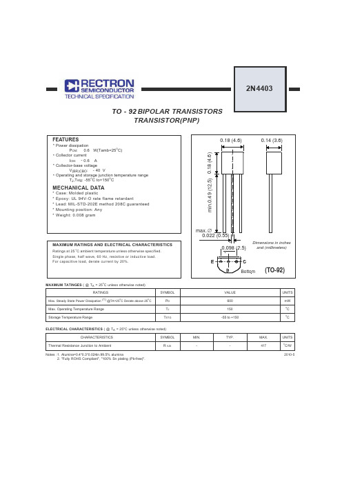
2010-5ELECTRICAL CHARACTERISTICS ( @ T A = 25C unless otherwise noted)MAXIMUM TATINGES ( @ T A = 25C unless otherwise noted)Notes :CHARACTERISTICSSYMBOL UNITS417oC/WThermal Resistance Junction to AmbientRATINGSMax. Steady State Power Dissipation (1) @TA=25oC Derate above 25CMax. Operating Temperature Range Storage Temperature RangeSYMBOL P D T J T STGR q JAVALUE MAX.-TYP.-MIN.UNITS mW6001. Alumina=0.4*0.3*0.024in.99.5% alumina2. "Fully ROHS Compliant", "100% Sn plating (Pb-free)".150-55 to +150o C oCTRANSISTOR(PNP)ELECTRICAL CHARACTERISTICS(@TA=25O C unless otherwise noted)OFF CHARACTERISTICSON CHARACTERISTICS (1)ChatacteristicCollector-Emitter Breakdown Voltage(1) (I C = -1.0 mAdc, I B = 0) Collector-Base Breakdown Voltage (I C = -0.1mAdc, I E = 0)Emitter-Base Breakdown Voltage (I E = -0.1mAdc, I C = 0)Base Cutoff Current (V CE = -35Vdc, V BE(off)= -0.4Vdc)Collector Cutoff Current (V CE = -35Vdc, V EB = -0.4Vdc)DC Current Gain (I C = -0.1mAdc, V CE = -1.0Vdc)(I C = -10mAdc, V CE = -1.0Vdc)(I C = -1.0mAdc, V CE = -1.0Vdc)V (BR)CEO -40-Vdc V (BR)CBO -40-Vdc V (BR)EBO-5.0-Vdc I CEXI BEV --0.1--0.1hFE30--60-100-100300uAdcuAdc Symbol Min Max Unit(I C = -150mAdc, V CE = -2.0Vdc)Collector-Emitter Saturation Voltage (1) (I C = -150mAdc, I B = -15mAdc)(I C = -500mAdc, I B = -50mAdc)(I C = -500mAdc, V CE = -2.0Vdc)Vdc V CE(sat)20---0.4--0.75VdcV BE(sat)-0.75-0.95--1.3Base-Emitter Saturation Voltage (1) (I C = -150mAdc, I B = -15mAdc)(I C = -500mAdc, I B =-50mAdc)SMALL-SIGNAL CHARACTERISTICSSWITCHING CHARACTERISTICSf T 200-MHz Current-Gain-Bandwidth Product (I C = -20mAdc, V CE = -10Vdc, f= 100MHz)C cb C eb -8.5pF pF t d t r t s t f----nsnsh ie -301.515kohms h re 0.18.060500X 10-4h fe 1.0100-h oe225301520umhosOutput Capacitance (V CB = -10Vdc, I E = 0, f= 1.0MHz)Input Capacitance (V EB = -0.5Vdc, I C = 0, f= 1.0MHz)Voltage Feedback Ratio (V CE = -10Vdc, I C = -1.0mAdc, f= 1.0kHz)Output Admittance (V CE = -10Vdc, I C = -1.0mAdc, f= 1.0kHz)(V CC = -30Vdc, V EB = -2.0Vdc, I C = -150mAdc, I B1= -15mAdc)(V CC = -30Vdc, I C = -150mAdc, I B1= I B2= -15mAdc)Input lmpedance (V CE = -10Vdc, I C = -1.0mAdc, f= 1.0kHz)Small-Signal Current Gain (V CE = -10Vdc, I C = -1.0mAdc, f= 1.0kHz)Delay Time Rise Time Storage Time Fall TimeNote :Pulse Test: Pulse Width <300ms,Duty Cycle <2.0%--RATING AND CHARACTERISTICS CURVES ( )Figure 1. CapacitancesFigure 3. Turn-On TimeFigure 5. Storage Time0.1 0.2 0.3 0.5 0.7 1.0 2.0 3.0 5.0 10 20 3010 20 30 50 70 100 200 300 500C A P A C I T A N C E (p F )t s ',S T O R A G E T I M E (n s )t , T I M E (n s )t , T I M E (n s )Q , C H A R G E (n C )REVERSE VOLTAGE (V)I C ,COLLECTOR CURRENT (mA)I C , COLLECTOR CURRENT (mA)I C ,COLLECTOR CURRENT (mA)Figure 4. Rise Times10203050701007.05.010 20 30 50 70 100 200 300 50010 20 30 50 70 100 200 300 500I C ,COLLECTOR CURRENT (mA)10 20 30 50 70 100 200 300 500Figure 2. Charge Data0.20.30.50.71.0100.12.03.05.07.025OC100O C2N4403RATING AND CHARACTERISTICS CURVES ()h o e , O U T P U T A D M I T T A N C E (u m h o s )h r e , V O L T A G E F E E D B A C K R A T I O (X 10-4)0.1 0.2 0.3 0.5 0.7 1.0 2.0 3.0 5.0 7.0 100.1 0.2 0.3 0.5 0.7 1.0 2.0 3.0 5.0 7.0 1050 100 200 500 1.0k 2.0k 5.0k 10k 20k 50kN F , N O I S E F I G U R E (d B )N F ,N O I S E F I G U R E (d B )Figure 6.Frequency EffectsI C , COLLECTOR CURRENT (mAdc)I C , COLLECTOR CURRENT (mAdc)Figure 8.Cuttent GainFigure 9.Input ImpedanceR S , SOURCE RESISTANCE (OHMS)Figure 7.Source Resistance EffectsI C , COLLECTOR CURRENT (mAdc)I C , COLLECTOR CURRENT (mAdc)Figure 11.Temperature CoefficientsFigure 10.Voltage Feedback Ratio 0.1 0.2 0.3 0.5 0.7 1.0 2.0 3.0 5.0 7.0 100.1 0.2 0.3 0.5 0.7 1.0 2.0 3.0 5.0 7.0 10f, FREQUENCY (KHz)46810200.01 0.02 0.05 0.1 0.2 0.5 1.0 2.0 5.0 10 20 50 100V CE = -10Vdc, T A = 25CBandwidth = 1.0Hz2N4403RATING AND CHARACTERISTICS CURVES ()Figure 12. DC Current GainFigure 13. Collector Saturation RegionFigure 14. "ON" Voltages Figure 15. Temperature Coefficients0.1 0.2 0.3 0.5 0.7 1.0 2.0 3.0 5.0 7.0 10 20 30 50 70 100 200 300 5000.005 0.01 0.02 0.03 0.05 0.07 0.1 0.2 0.3 0.5 0.7 1.0 2.0 3.0 5.0 7.0 10 20 30 500.1 0..2 0.5 1.0 2.0 5.0 10 20 50 100 200 5000.1 0..2 0.5 1.0 2.0 5.0 10 20 50 100 200 500h F E , N O R M A L I Z E D C U R R E N T G A I NV C E , C O L L E C T O R - E M I T T E R V O L T A G E (V )V O L T A G E (V )C O E F F I C I E N T (m V /OC )I C , COLLECTOR CURRENT (mA)I B , BASE CURRENT (mA)I C , COLLECTOR CURRENT (mA)I C , COLLECTOR CURRENT (mA)0.40.60.81.00.20.30.50.71.03.00.22.030442NRectron Inc reserves the right to make changes without notice to any productspecification herein, to make corrections, modifications, enhancements or other changes. Rectron Inc or anyone on its behalf assumes no responsibility or liabi- lity for any errors or inaccuracies. Data sheet specifications and its information contained are intended to provide a product description only. "Typical" paramet- ers which may be included on RECTRON data sheets and/ or specifications ca- n and do vary in different applications and actual performance may vary over ti- me. Rectron Inc does not assume any liability arising out of the application or use of any product or circuit.Rectron products are not designed, intended or authorized for use in medical, life-saving implant or other applications intended for life-sustaining or other rela- ted applications where a failure or malfunction of component or circuitry may di- rectly or indirectly cause injury or threaten a life without expressed written appr- oval of Rectron Inc. Customers using or selling Rectron components for use in such applications do so at their own risk and shall agree to fully indemnify Rect- ron Inc and its subsidiaries harmless against all claims, damages and expendit- ures.DISCLAIMER NOTICE。

安全用LJA LJM LJKLJS-E 系列模铸带电磁锁定安全钥匙开关模铸外壳带电磁锁定安全钥匙开关。
●带UL/CSA/CE标志。
● 带接点强制开离机构(仅限常闭接点)。
●高密封性(IP67)。
·模铸外壳。
·标准配备指示灯。
■型号一览表●本体UL/CSA/CE详细尺寸请在图纸中确认。
→●操作钥匙安全用LJALJMLJK■内部开关使用类别 AC-15 :电磁负载DC-13 :电磁负载Ue:额定使用电压Ie :额定使用电流LJS-E的内部开关采用常闭/常开电气独立(Zb)的接点结构。
另外,采用接点熔结时可强制性开离的(仅限常闭接点)接点强制开离机构。
■性能压入强制开离注.处处平圆柱头螺栓平圆柱头螺栓安装孔操作钥匙插入(NORMAL)状态操作钥匙插入(NORMAL)状态安全用LJALJMLJK ■接点动作(单位:mm)型号LJS-E5312, LJS-E5512LJS-E7312, LJS-E7512电路图:接点闭:接点开:不稳定■动作特性/外形尺寸图● 本体操作钥匙拉拔保持力(锁定时)2,000N强制开离力(最小)20N处处处处处处安全用LJA LJM LJK●操作钥匙LJS-Z01(单位:mm)LJS-Z03LJS-Z02■电路例●EN954-1类别1的电路例使用保险丝以防止因电缆线损坏或人为变更而造成常闭接点闭合,其电路如下。
N.C.+N.O.+N.O.(LJS-E5312)●EN954-1类别3的电路例无监控,在开关接点中具有冗余性接点的电路例N.C.+N.C.+N.O.(LJS-E7312)(1)电磁线圈(2)备用接点E1-E2 : 电磁线圈电源(无极性)43-44 : 电磁线圈信号用接点13-14 : 冗余用接点33-X1 : LED(橙):操作钥匙拔出状态下通电。
51-X1 : LED(绿):操作钥匙插入锁定状态下通电。
21-52 : 安全所需的接线(1)电磁线圈(2)备用接点E1-E2 : 电磁线圈电源(无极性)43-44 : 电磁线圈信号用接点31-32 : 冗余用接点13-X1 : LED(橙):操作钥匙拔出状态下通电。