电力系统静态安全分析new
- 格式:ppt
- 大小:332.00 KB
- 文档页数:8
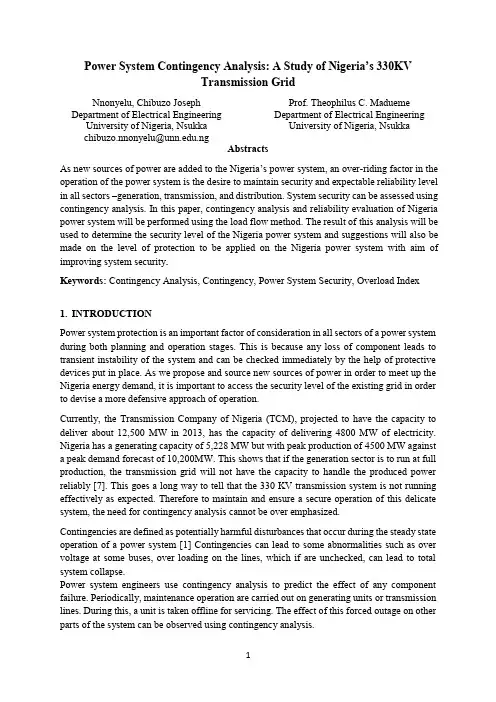
Power System Contingency Analysis: A Study of Nigeria’s 330KVTransmission GridNnonyelu, Chibuzo Joseph Department of Electrical Engineering University of Nigeria, Nsukkachibuzo.nnonyelu@.ngProf. Theophilus C. MaduemeDepartment of Electrical EngineeringUniversity of Nigeria, Nsukka AbstractsAs new sources of power are added to the Nigeria’s power system, an over-riding factor in the operation of the power system is the desire to maintain security and expectable reliability level in all sectors –generation, transmission, and distribution. System security can be assessed using contingency analysis. In this paper, contingency analysis and reliability evaluation of Nigeria power system will be performed using the load flow method. The result of this analysis will be used to determine the security level of the Nigeria power system and suggestions will also be made on the level of protection to be applied on the Nigeria power system with aim of improving system security.Keywords: Contingency Analysis, Contingency, Power System Security, Overload Index1.INTRODUCTIONPower system protection is an important factor of consideration in all sectors of a power system during both planning and operation stages. This is because any loss of component leads to transient instability of the system and can be checked immediately by the help of protective devices put in place. As we propose and source new sources of power in order to meet up the Nigeria energy demand, it is important to access the security level of the existing grid in order to devise a more defensive approach of operation.Currently, the Transmission Company of Nigeria (TCM), projected to have the capacity to deliver about 12,500 MW in 2013, has the capacity of delivering 4800 MW of electricity. Nigeria has a generating capacity of 5,228 MW but with peak production of 4500 MW against a peak demand forecast of 10,200MW. This shows that if the generation sector is to run at full production, the transmission grid will not have the capacity to handle the produced power reliably [7]. This goes a long way to tell that the 330 KV transmission system is not running effectively as expected. Therefore to maintain and ensure a secure operation of this delicate system, the need for contingency analysis cannot be over emphasized.Contingencies are defined as potentially harmful disturbances that occur during the steady state operation of a power system [1] Contingencies can lead to some abnormalities such as over voltage at some buses, over loading on the lines, which if are unchecked, can lead to total system collapse.Power system engineers use contingency analysis to predict the effect of any component failure. Periodically, maintenance operation are carried out on generating units or transmission lines. During this, a unit is taken offline for servicing. The effect of this forced outage on other parts of the system can be observed using contingency analysis.As demand for power increases, more generating units are installed in Nigeria with no corresponding increase in transmission capacity. This makes the transmission lines run at their maximum power capacity which is very dangerous as there is too much power in the system at any moment. This power will be shifted to any available portion of the transmission system in case of any contingency thereby overloading the available portion. This effect can be analysed by the calculation of Line Outage Distribution Factor (LODF). Also, the overloading index of the remaining lines will can be obtained equally.2.POWER SYSTEM SECURITYOne of the most important factors in the operation of any power system is the desire to maintain system availability and reliability. This ensures a secure operation of the system and improved economic operation. Power system security is the ability of the system to withstand one or more component outages with the minimal disruption of service or its quality. System security involves practices designed to keep the system operating in emergency state when components fail and to restore it to its preventive state. For instance, a generating unit may break down or have to be taken off-line for maintenance purposes. This leads to frequency and voltage instability as the available generating unit experiences more loads than usual, hence frequency drops and bus voltages lowers. If this is not foreseen and defensively prevented by use of protective devices such as relays for load shading, it can lead to the collapse of the concerned system. Therefore the control objective in the emergency state is to relieve system stress by appropriate actions while economic consideration becomes of secondary.2.1CONTINGENCY ANALYSISContingency analysis is the study of the outage of elements such as transmission lines, transformers and generators, and investigation of the resulting effects on line power flows and bus voltages of the remaining system. It represents an important tool to study the effect of elements outages in power system security during operation and planning. Contingencies referring to disturbances such as transmission element outages or generator outages may cause sudden and large changes in both the configuration and the state of the system. Contingencies may result in severe violations of the operating constraints. Consequently, planning for contingencies forms an important aspect of secure operation [2].There are various methods of contingency analysis which include the following:a.AC Load flow methodb.DC Load flow methodc.Z-Matrix methodd.Performance Index methodOf all the above listed methods, methods based on AC power flow calculations are considered to be deterministic methods which are accurate compared to DC power flow methods. In deterministic methods line outages are simulated by actual removal of lines instead of modelling. AC power flow methods are accurate but they are computationally expensive and excessively demanding of computational time. Because contingency analysis is the only toolfor detecting possible overloading conditions requiring the study by the power system planner computational speed and ease of detection are paramount considerations. [1]Results of contingency analysis are usually ranked based on some indices calculated during the analysis. The choice of performance index to calculate depends on the engineer. In a deregulated power system, a discernibly purely profit driven, economic operation is of utmost importance hence Available Transfer Capability (ATC) is normally calculated to ascertain the available transfer capability of the system in case of any contingency. Other Indices include Voltage Stability Index (VSI), Active Power Loading Performance Index (APLPI), Line Outage Distribution Factor (LODF), Line loadability, etc.Generally, once the current working state of a system is known, contingency analysis can be broken down into the following steps:a.Contingency definitionb.Contingency selectionc.Contingency evaluationContingency definition involves preparing a list of probable contingencies. This typically includes line outages and generator outages.Contingency selection process consists of selecting the set of most probable contingencies; they need to be evaluated in terms of potential risk to the system. Usually, fast power flow solution techniques such as DC power flow are used to quickly evaluate the risks associated with each contingency. But in this work, the Newton-Raphson load flow method will be used to ensure higher accuracy.Finally, the selected contingencies are ranked in order of their security, till no violation of operating limits is observed.The algorithm for a typical contingency analysis is shown in Figure 1.Figure 1: Algorithm of a typical contingency analysis2.2 LINE LOADABILITYLine Loadability can be defined as Transmission-line voltages decrease when heavily loaded and increase when lightly loaded. When voltages on EHV lines are maintained within ±5% of rated voltage, corresponding to about 10% voltage regulation, unusual operating problems are not encountered. Ten percent voltage regulation for lower voltage lines including transformer-voltage drops is also considered good operating practice.In addition to voltage regulation, line loadability is an important issue. Three major line-loading limits are:a.the thermal limit,b.the voltage-drop limit, andc.the steady-state stability limit.The maximum temperature of a conductor determines its thermal limit. Conductor temperature affects the conductor sag between towers and the loss of conductor tensile strength due to annealing. If the temperature is too high, prescribed conductor-to-ground clearances may not be met, or the elastic limit of the conductor may be exceeded such that it cannot shrink to its original length when cooled.Conductor temperature depends on the current magnitude and its time duration, as well as on ambient temperature, wind velocity, and conductor surface conditions.The loadability of short transmission lines (less than 80 km in length) is usually determined by the conductor thermal limit or by ratings of line terminal equipment such as circuit breakers.For longer line lengths (up to 300 km), line loadability is often determined by the voltage-drop limit. Although more severe voltage drops may be tolerated in some cases, a heavily loaded line with V R/V S ≥ 0.95 is usually considered safe operating practice. For line lengths over 300 km, steady-state stability becomes a limiting factor [4].3.METHODOLOGYIn this paper, the AC load flow method of contingency analysis was adopted. The Newton-Raphson load flow algorithm, an algorithm under the AC load flow method, was used to solve the power flow problems during the analysis using MATLAB. This is because the NRLF method has more accuracy than other AC Load flow methods and converges faster. Newton-Raphon’s Load flow method is discussed more in [3, 4].3.1 Calculating System Line Overload Index (SLOI)To obtain the overall system overload index, a new performance index was proposed and calculated based on the Line Loadability discussed in Section 2.2. As stated, for safe operation, the ratio of the receiving end voltage and the sending end voltage must be greater than 0.95. This newly proposed index relies on this to calculate the system line overload index. It helps tell the system designer at a glance, the lines that should be given utmost attention in terms of protection. SLOI is computed by equation (1):SLOI=1− [min(V RV S )]k(1)whereV R, V S are the receiving end and sending end voltages respectively, andk the number of lines whose V R/V S < 0.95The Nigerian transmission grid is shown in Figure 2 with the single line diagram shown in Figure 3.Figure 2: the Nigerian power system. Blue lines indicate the 330-KV lines(Source: Nigeria System Operator)Figure 3: one-line diagram of the Nigeria 330-KV transmission gridThe network parameters – generator data, load data, and line & transformer data, of the Nigeria power system as used in this work were collated from [8, 9, 10] and are shown in tables 1, 2, and 3 respectively.Table 1: Generator data3.1 Simulation of Line OutageSimulation of transmission line outage is carried out by the formulation of the corresponding admittance matrix [5]. For instance, after outage of a line connecting bus ‘a’and ‘b’, the components of the Y bus that will be affected are Y aa, Y bb, Y ab, and Y ba. For a ‘π-modelled’transmission line, the admittance values after this outage is obtained by subtracting the admittance of the line a-b and the shunt susceptance jb ab/2 and jb ba/2 from Y aa and Y bb.Line outages was simulated by simply removing the line information from the line data matrix. This is similar to the line not existing initially as the information no longer exists.3.2 Simulation of Generator OutageThis simulates mainly outage of one unit (or more) in a power station. Let the total generation for the station at bus ‘m’ be P gm, and assume that there exist identical (g) units, then [6]:)(2) P gm′=P gm−n(P gmgwhereP’gm: Active power generated at bus m after the outageP gm: Active power generated at bus m before the outagen: Number of outage generation units in the stationP gm/g: Active power generated at bus m per generator unitIn this work, generator outages were not simulated as only the effect of line outages were desired.4.Results and DiscussionThe results of the analysis (the SLOI) is shown in Table 4 ordered by the SLOI from the most critical to the least critical.The result as shown in Table 4 contains the SLOI values of the different lines for line outages. It has been organised in the order in descending order.This shows that the outage of line 11 to 14 (Oshogbo to Aiyede) will have the most critical effect on the system followed by 11 – 15, 16 – 20, 20 – 24, 25 – 16. These lines have been shown to pose serious danger on the system stability if they fail, and therefore should be secured defensively to avoid the level of system instability caused by the outage of any of the lines.5.ConclusionFrom this study, it is has been shown with values, the importance of operating the transmission system defensively to avoid system collapse due to overloading. Also, the writer suggests that the Transmission Company of Nigeria (TCN) should adopts the (Flexible AC Transmission), FACT devices as they can improve the lines active power capability in any contingency event as have faster switching than the traditional compensation devices. Also additional lines should be used to connect Oshogbo to Aiyede through different routes to create more links for power to be transmitted through to Lagos area in order to reduce the SLOI value of Oshogbo to Aiyede line.References[1] Chary, D. M., “Contingency Analysis in Power Systems, Transfer CapabilityComputation and Enhancement Using Facts Devices in Deregulated Power System.”Ph.D. diss., Jawaharlal Nehru Technological University, 2011[2] Wood, A. J.; Wallenberg, B. F., “Power Generation, Operation and Control”. 2nd ed.,New York/USA: John Wiley& Sons, 1996, pp. 410-432.][3] Saadat, H., Power System Analysis, New Delhi: McGraw Hill, 2002, pp 189 – 256.[4] Glover, J. D., Sarma, M. S., Overbye, T. J., Power System Analysis and Design, 5h ed.Stamford: Cengage Learning, 2012.[5] Nara, K.,Tanaka,K., Kodama, H., Shoults, R. R., Chen, M. S., Olinda, P. V. andBertagnolli, D., “On-Line Contingency Selection for voltage Security Anal ysis”, ibid, Vol.PAS – 104, pp. 847-856, April 1985.[6] Mohamed, S. E. G., Mohamed, A. Y., and Abdelrahim, Y. H., “Power SystemContingency Analysis to detect Network Weaknesses”, Zaytoonah UniversityInternational Engineering Conference on Design and Innovation in Infrastructure, Amman, Jordan, pp. I3-4 Jun., 2012.[7] “Nigeria's Power Generation hits 5,228 Mega Watt”, Nigeria Compass, May 4, 2013.[Online]. Available: /index.php/special-desk/business-news/12769-nigerias-power-generation-hits-5228-megawatts [Accessed July 15, 2013]. [8] Ogbuefi, U. C., “A Powerflow Analysis of Niegria Power System with Compensation onSome Buses”,PhD thesis, University of Nigeria, Nsukka, Nigeria, 2013.[9] Nigeria System Operator, “Profile of Transmission”, 2011. [Online]. Available:/spread/profile/ [Accessed: July 15, 2013].[10] Onohaebi, O. S., “Power Outages in Nigeria Transmission Grid,” Research Journal ofApplied Science, vol. 4, Issue 1, pp 1- 9, 2009.。
电力系统静态安全分析方法研究电力系统是现代社会的基础设施之一,它不仅提供了电力服务,同时也对工业生产、商业发展、社会稳定起着至关重要的作用。
因此,保障电力系统的安全是非常重要的任务。
在电力系统运行中,静态安全分析是一项重要的工作。
本文将介绍电力系统静态安全分析的方法,分析其优缺点,并探讨未来的发展方向。
一、静态安全分析方法静态安全分析是指在电力系统正常运行状态下,研究其稳定性、断电容忍能力、电压控制能力等,从而保证电源的可靠性和稳定性。
静态安全分析的主要方法包括潮流分析、潮流限制分析、电压稳定裕度分析、可靠性评估等。
1、潮流分析潮流分析是电力系统静态安全分析的基础工具,它是用来计算电力系统各节点的电压、电流、功率等技术参数的一种数学方法。
潮流分析可以用来确定输电线的负载率、测量变压器的功率损耗、计划电力系统的运行条件等。
它不仅可以满足工程实际操作需要,还可以提供对电力系统的可靠性和稳定性的静态分析。
2、潮流限制分析潮流限制分析,指通过模拟各种故障和异常情况,评估电力系统在这些情况下的运行能力。
通过潮流限制分析,可以确定电力系统的最大电流、最大功率、最大负荷量等。
它可以帮助工程师找出电力系统中的故障点,并在紧急情况下制定合适的应对措施。
3、电压稳定裕度分析电压稳定裕度分析是指评估电力系统在负荷变化和扰动情况下的电压稳定性。
其分析结果可以用来指导电力系统的电压控制策略,以确保电力系统在正常工作条件下保持稳定和动态响应。
电压稳定裕度分析使电力系统管理人员能够更好地预测故障,并采取必要的措施,来避免电力系统的运行中断和不稳定因素的发生。
4、可靠性评估可靠性评估一般用来评价电力系统的负荷容量、发电机的使用年限、元件的可靠性、维护成本、电源的备用容量等问题。
可靠性评估可以从实践中获得足够的数据来确定电力系统的设计和运行要求,制定适当的运行和维护计划。
它在电力系统的长期规划和设计方面起着至关重要的作用,可对系统性能进行独立评估,从而优化可靠性、稳定性、安全性和经济性。


电力系统静态稳定性分析摘要近几年,电力系统的规模日益增大,系统的稳定问题越来越严重地威胁着电网的安全稳定运行,对电力系统的静态稳定分析也成为一个十分重要的问题。
为提高和保证电力系统的稳定运行,本文主要阐述了电力系统静态稳定性的基本概念,对小干扰法的基本原理做了研究,并利用小干扰法对简单的单机电力系统进行了简要的分析。
且为了理解调节励磁对电力系统稳定性的影响,本文做了简要要研究,并以单机系统为实例,进行了简单地分析。
本文通过搜集相关资料,整理了保证和提高电力系统静态稳定性的措施。
关键词:电力系统,静态稳定,小干扰分析法 ,励磁调节ABSTRACTIn recent years, the scale of power system is increasing,so system stability problem is increasingly serious threat to the safe and stable operation of power grid,and power system static stability analysis has become a very important problem.In order to improve and ensure the stable operation of electric power system, this paper mainly expounds the basic concept of the static stability of power system,using the small disturbance method basic principle to do the research, and the use of small disturbance method for simple stand-alone power system undertook brief analysis. And in order to understand the regulation of excitation effects on the power system stability, this paper makes a brief to research, and single system as an example, undertook simple analysis.In this paper, by collecting relevant information, organize the guarantee and improve the power system static stability measures.Key words power system , static stability, small signal analysis method of excitation regulator目录摘要IABSTRACTII第1章绪论11.1 研究电力系统静态稳定性的目的以与原则11.2 本文采用的解决电力系统静态稳定性问题的方法11.3 课题研究的成果和意义1第2章电力系统静态稳定性简析22.1 电力系统的基本概念22.11电力系统的定义22.12电力系统的运行特点和要求22.2电力系统静态稳定性的基本概念22.21电力系统静态稳定性的定义22.22电力系统静态稳定性的分类32.23 电力系统静态稳定性的定性分析7第3章小扰动法分析简单系统的静态稳定性113.1 小扰动法基本原理113.2小扰动法分析简单电力系统静态稳定性12第四章调节励磁对电力系统静态稳定性的影响164.1 不连续调节励磁对静态稳定性的影响164.2 实例分析励磁调节对稳定性的影响17第5章提高电力系统静态稳定性的措施205.1提高静态稳定性的一般原则205.2 改善电力系统基本元件的特性和参数215.21 改善系统电抗215.22改善发电机与其励磁调节系统的特性215.23 采用直流输电225.3 采用附加装置提高电力系统的静态稳定性225.31 输电线路采用串联电容补偿225.32 励磁系统采用电力系统稳定器PSS 装置23 第6章结论24辞25参考文献26第1章 绪论1.1 研究电力系统静态稳定性的目的以与原则电力系统是一个复杂的大规模的非线性动态系统,其稳定性分析是是电力系统规划和运行的最重要也是最复杂的任务之一。
静态安全分析的定义电力系统各种运行状态的定义及其相互转换关系安全性和可靠性的区别和联系电力系统安全分析的内容和流程各种静态等值的原理和特点故障组的定义预想事故分析的步骤从安全角度来看,电力系统运行的五种状态是什么?简述每种状态的特点。
(03A)电力系统的可靠性、安全性和稳定性各有什么含义?简述各自的主要研究内容.(03A、05A)什么是电力系统的可靠性?有哪些研究内容?(05B)什么是静态安全分析和动态安全分析?安全分析是指应用潮流计算方法,对运行中的网络或某一研究下的网络,按N—1原则,研究一个个运行元件因故障退出运行后,网络的安全性及安全裕度。
静态安全分析是研究元件有无过负荷及母线电压水平是否符合要求,有无越限,以检验电网结构强度和运行方式是否满足安全运行的要求。
动态安全分析是研究线路功率是否超稳定极限。
安全分析从功能上课分为两大模块:一块为故障排序,即按N-1故障严重程度自动排序,另一块为阿娜全评估。
对静态安全分析而言,也就是进行潮流计算,动态安全分析则要进行稳定计算分析。
安全分析(上题)的内容和流程:安全分析的功能就是应用计算机使运行人员及时获得实时数据并对下一时刻中可能出现的事故进行快速而详尽的计算分析,从而得出较完整而准确的结论。
电力系统的可靠性、安全性和稳定性各有什么含义?简述各自的主要研究内容。
(可靠性和安全性的区别与联系)可靠性:(安全性见第一题)为保证供电的持续性,也就是说,要求系统安全、可靠,首先应明确安全性(security)和可靠性(reliability)的定义。
在早期的文献中,这两个术语有时混用。
大体上说有两种定义方法,方法一:1)在系统规划设计或历史统计方面,系统保证对负荷持续供电的能力,称为可靠性。
它涉及到较长的时间段,是一个长时期持续供电的平均值概念,为此必须考虑众多可能的运行状态及各种故障;2)在系统运行方面,当系统发生故障时,保证对负荷持续供电的能力,称为安全性.它涉及到系统的当前现状和突然发生的故障,因此是一个时变的或瞬时性的问题。
电力系统静态稳定性分析一、电力系统静态稳定性的概念静态稳定性是指电力系统在外部扰动(如大负荷突然失去或电网连锁故障等)下,维持基本工作状态的能力。
电力系统静态稳定性分析主要研究系统的平衡和不平衡工作状态,以及在系统发生扰动后的响应过程。
主要包括潮流分析、电力系统潮流控制、稳定裕度分析等。
二、电力系统静态稳定性分析方法1.潮流分析潮流分析是电力系统静态稳定性分析的基础。
通过潮流分析可以确定系统各个节点的电压、电流、功率等参数,以及线路、变压器的负载情况。
潮流计算方法主要包括高斯-赛德尔迭代法、牛顿-拉夫逊迭代法和直接潮流法等。
通过对潮流分析的结果进行评估和判断,可以得出系统的稳定性状况。
2.电力系统潮流控制电力系统潮流控制主要通过调整发电出力和负荷的分配来实现。
常用的方法包括静态无功补偿装置的投入和退出、变压器调压控制、发电机调压控制、风电和光伏发电等分布式电源的接入控制等。
通过潮流控制,可以有效控制系统的电压、无功功率等参数,从而提高系统的稳定性。
3.稳定裕度分析稳定裕度分析是针对电力系统可能发生的故障和异常情况进行评估和分析,以判断系统在不同工况下的稳定性水平。
常见的稳定裕度指标包括暂态稳定裕度、稳定边界等。
通过稳定裕度分析,可以识别和解决系统的潜在稳定问题,保证系统的稳定运行。
三、电力系统静态稳定性常见问题1.电压稳定问题:电力系统电压的稳定性是影响系统静态稳定性的重要因素。
过高或过低的电压都会导致系统稳定性下降,甚至发生电压失稳。
通过控制无功功率的输出、调整电网结构等措施,可以有效解决电压稳定问题。
2.功率平衡问题:系统内的功率平衡是保证系统稳定运行的基础。
发电出力和负荷之间的失衡会导致系统频率的变化,进而影响系统的稳定性。
通过合理调整发电出力和负荷分配,保持功率平衡,可以提高系统的静态稳定性。
3.事故短路问题:电力系统中的事故短路是可能引起系统瞬态稳定失稳的重要因素。
当发生事故短路时,会导致系统的电压下降、频率波动等现象,进一步影响系统的稳定性。