samson 低温阀门中文样本
- 格式:pdf
- 大小:1.69 MB
- 文档页数:8
SAMSON 3780说明书调节阀维护及操作规程DCS系统对调节阀的控制主要通过调节阀自身的电气阀门定位器完成。
我司生产线上的调节阀为德国SAMS ON调节阀,SAMSON调节阀采用智能数字阀门定位器(3780,HART协议数字通信),其控制精度高,运行稳定。
定位器的主要性能介绍如下:结构与工作原理HART电气定位器是为连接气动调节阀而设计的,它可确保阀杆位置(受控变量)与控制信号(参考变量)之间的对应关系。
它将控制装置 4至20mA的输出信号和调节调的行程相比较,并产生一个相应的压力信号作为输出变量。
为此,用户需要提供辅助气源压力1.4-6巴。
定位器辅助能源是由4到20mA参考变量信号提供。
定位器由一个感应,非接触或位移传感系统,一个由2/2-通开关阀组成的电控阀块以及一个电控单元组成。
电控单元包含两个用于处理控制算法及管理通讯的微控器.一旦实际阀门行程值(实际值)与参考变量(设定点)之间出现偏差,微控器就会产生一个二进制脉冲调制信号去控制两个 2/2通开关阀,且分别由一个指定的放大器来控制。
其中一个阀控制排气,另一个控制气源.气源阀(3)将供气(7气源压力1·46巴)送到执行器(填充)。
排气阀(将执行器排出空气流排放到大气中(排气)。
这些开关阀即可以有开关状态—一常开。
常闭—一也可产生可变宽度的单脉冲。
对于这两个受控_阀门,阀林将会移动到与参考变连量相对应的位置。
如果没有系统偏差气源阀和排气阀都将关闭。
作为一个标准功能,定位器配有一个故障信息输出(根据DDN19Z34,NANUR标准的进制输出),用于向控制室发送故障信号。
成的激活位于定位器铰接盖上的写保护开关‘可防止设定被HART通讯修改。
作为对标准定位器型号的补充,有几个附加的选项用于扩展定位器功能。
带眼位开关的定位器为了在故障一安全电路中指示出阀门的最终位置,两个软件限位开关或两个接近开关被带强制排空功能的定位器一个控制定位器的6-24V电压信号,使得信压力施加到执行器。
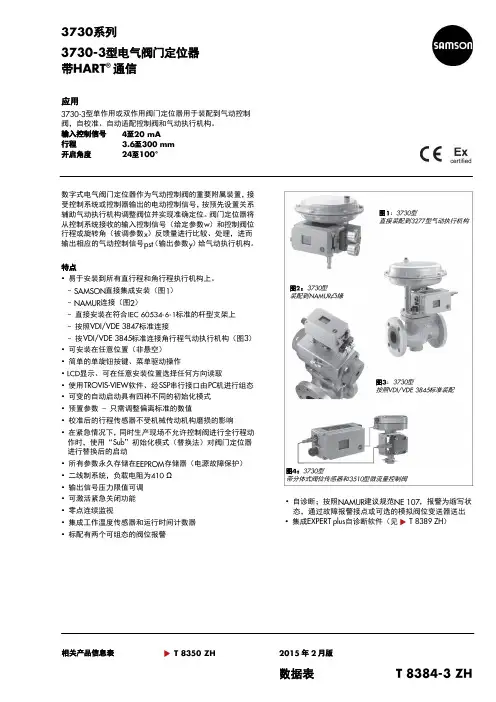
系列型电气阀门定位器带通信应用型单作用或双作用阀门定位器用于装配到气动控制阀,自校准、自动适配控制阀和气动执行机构。
输入控制信号至行程至开启角度至数字式电气阀门定位器作为气动控制阀的重要附属装置,接受控制系统或控制器输出的电动控制信号,按预先设置关系辅助气动执行机构调整阀位并实现准确定位。
阀门定位器将从控制系统接收的输入控制信号(给定参数)和控制阀位行程或旋转角(被调参数)反馈量进行比较、处理,进而输出相应的气动控制信号(输出参数)给气动执行机构。
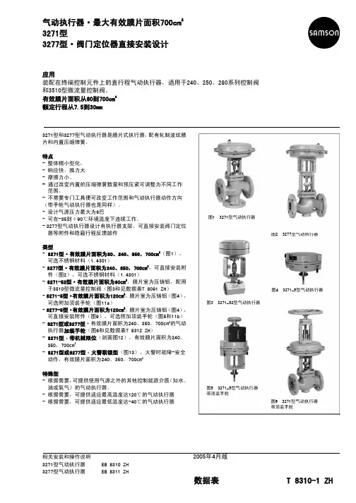
特点•易于安装到所有直行程和角行程执行机构上。
-直接集成安装(图)-连接(图)-直接安装在符合标准的杆型支架上-按照标准连接-按标准连接角行程气动执行机构(图)•可安装在任意位置(非悬空)•简单的单旋钮按键、菜单驱动操作•显示、可在任意安装位置选择任何方向读取•使用软件、经串行接口由机进行组态•可变的自动启动具有四种不同的初始化模式•预置参数-只需调整偏离标准的数值•校准后的行程传感器不受机械传动机构磨损的影响•在紧急情况下,同时生产现场不允许控制阀进行全行程动作时,使用“”初始化模式(替换法)对阀门定位器进行替换后的启动•所有参数永久存储在存储器(电源故障保护)•二线制系统,负载电阻为Ω•输出信号压力限值可调•可激活紧急关闭功能•零点连续监视•集成工作温度传感器和运行时间计数器•标配有两个可组态的阀位报警•自诊断;按照建议规范,报警为缩写状态,通过故障报警接点或可选的模拟阀位变送器送出•集成自诊断软件(见)相关产品信息表年月版数据表图:型直接装配到型气动执行机构图:型装配到凸缘图:型按照标准装配图:型带分体式阀位传感器和型微流量控制阀类型-型数字式电气阀门定位器,现场操作、就地通信使用接口,自诊断、通信。
-型数字式电气阀门定位器,现场操作、就地通信使用接口,自诊断、压力传感器用于监控气源和信号压力附加可选-感应式阀位开关(接近开关)-二线制模拟信号的阀位变送器-电磁阀强制排气功能-二进制输入-分体式阀位传感器(图)-模拟输入-不锈钢外壳-泄漏传感器监控阀座泄漏工作原理型数字式电气阀门定位器装配到气动控制阀。
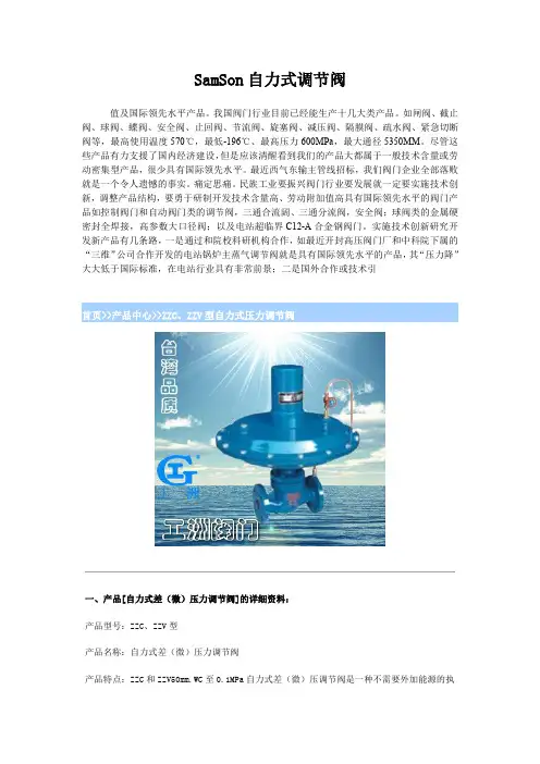
SamSon自力式调节阀值及国际领先水平产品。
我国阀门行业目前已经能生产十几大类产品。
如闸阀、截止阀、球阀、蝶阀、安全阀、止回阀、节流阀、旋塞阀、减压阀、隔膜阀、疏水阀、紧急切断阀等,最高使用温度570℃,最低-196℃、最高压力600MPa,最大通径5350MM。
尽管这些产品有力支援了国内经济建设,但是应该清醒看到我们的产品大都属于一般技术含量或劳动密集型产品,很少具有国际领先水平。
最近西气东输主管线招标,我们阀门企业全部落败就是一个令人遗憾的事实。
痛定思痛。
民族工业要振兴阀门行业要发展就一定要实施技术创新,调整产品结构,要勇于研制开发技术含量高、劳动附加值高具有国际领先水平的阀门产品如控制阀门和自动阀门类的调节阀,三通合流阔、三通分流阀,安全阀;球阀类的金属硬密封全焊接,高参数大口径阀;以及电站超临界C12-A合金钢阀门。
实施技术创新研究开发新产品有几条路,一是通过和院校科研机构合作,如最近开封高压阀门厂和中科院下属的“三维”公司合作开发的电站锅炉主蒸气调节阀就是具有国际领先水平的产品,其“压力降”大大低于国际标准,在电站行业具有非常前景;二是国外合作或技术引型自力式压力调节阀一、产品[自力式差(微)压力调节阀]的详细资料:产品型号:ZZC、ZZV型产品名称:自力式差(微)压力调节阀产品特点:ZZC和ZZV50mm.WC至0.1MPa自力式差(微)压调节阀是一种不需要外加能源的执行器产品。
可用于公称压力PN0.1、PN10。
差(微)压均可分段调节。
从50mm.WC至0.1MPa。
其用途十分广泛,可用于工业燃烧炉系统,控制两种物料,如煤气、空气流量配比,以达理想燃烧。
用于氢冷发电机组密封油系统,控制密封油与氢气间压力差,以确保可靠密封。
当差压阀的低压端通大气即为微压阀(差压阀负压,端压,力为零)。
二、特点:●无需停止生产即可进行设定值的调整;●无填料,阀杆上、下活动时不存在磨擦,上密封绝对可靠●执行机构敏感元件极为灵敏,极微小的压力变化会被感测出来●阀体为四通形式,因而K、B 型可通用一种阀体三、自力式差(微)压力调节阀主要技术参数和性能指标(表一):额定行程(mm)20253240506580100公称压力PN(MPa)差压调节范围(KPa)ZZCP/ZZVP81120325080100160 ZZCN5383额定行程(mm)68101520公称压力PN(MPa)0.101.0差压调节范围(KPa )0.5~5.55~109~1413~1918~2422~2826~3331~3836~4442~5149~5856~6664~7876~9088~100介质温度(℃)≤80调节精度(%)≤10允许泄漏量(L/H )ZZCP/ZZVP 10-4×阀额定容量(IV 级)ZZCN 5×10⁻³×阀额定容量(II 级)四、自力式差(微)压力调节阀主要技术参数和性能指标(表二)单位:mm:公称通径(DN)20253240506580100A308394308394308394394394H ZZCP/ZZVP376465365445445490490510ZZCN536536570590LZZCP/ZZVP15016018020230290310350ZZCN222222310350重量(kg)1213151720283843导压管螺纹接头M16×1.5五、自力式差(微)压力调节阀主要技术参数和性能指标法兰尽寸(表三):公称通径(DN )20253240506580100DPN01PN10105115140150165185200220D1PN01PN107585100125145160180bPN01PN1016182022n-ΦPN01PN104-144-188-18fl×D2PN01PN102×563×563×763×843×993×1183×1323×156六、型号编制:订货须知:一、①自力式差(微)压力调节阀产品名称与型号②自力式差(微)压力调节阀口径③自力式差(微)压力调节阀是否带附件二、若已经由设计单位选定公司的自力式差(微)压力调节阀型号,请按自力式差(微)压力调节阀型号三、当使用的场合非常重要或环境比较复杂时,请您尽量提供设计图纸和详细参数,相关产品:气动调节阀ZHYO罐底调节阀ZZYVP氮封阀ZMAS型高压单座角型调节阀Z673H型气动浆液阀气动隔膜衬氟调节阀气动调节球阀ZJHP精小型气动薄膜调节阀自力式电控温度调节阀一、产品[自力式电控温度调节阀]的详细资料:产品型号:ZZWPE产品名称:自力式电控温度调节阀产品特点:自力式电控温度调节阀(适用于较大口径及导热油控制),该阀最大的特点只需普通220V电源,利用被自身能量,直接对蒸汽、热气、热油与气体等介质的温度实行自动调节和控制,亦可使用在防止对过热或热交换场合结构简单,操作方便,选用调温范围广、响应时间快、密封性能可靠,并可在运行中随意进行调节,因而广泛应用于化工食品、轻纺、宾馆与饭店等部门的热水供应。
![Samson 低温调节阀介绍资料 [兼容模式]](https://uimg.taocdn.com/7d98a8284b73f242336c5fe0.webp)
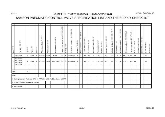
附件一:SAMSON 气动控制阀规格一览表及供货清单SAMSON PNEUMATIC CONTROL VALVE SPECIFICATION LIST AND THE SUPPLY CHECKLIST制造商:SAMSON AGe m / 序号a g N O . / 设计位号t y / 数量y p e / 型号N / 口径N u n i t s t a n d a r d / 压力单位N /C l a s s / 压力等级o d y M a t e r i a l / 阀体材质l a n g e f o r m / c o n n e c t i o n / 法兰形式/连接a c k i n g / 填料l u g / s e a t m a t e r i a l / 阀芯/阀座材质e a k a g e / 泄漏等级r e s s u r e b a l a n c e d / 压力平衡阀芯h a r a c t e r i s t i c / 流量特性v -v a l u e / 选择C v 值o i s e r e d u c t i o n / 减噪器l o w d i r e c t i o n / 流向o n n e t / 阀盖形式c t u a t o r t y p e / 执行器类型c t u a t o r s i z e [c m 2] / 执行器膜头面积t r o k e [m m ] / 行程a n d w h e e l / M a n u a l / 手轮/手动装置p r i n g r a n g e [b a r ] / 弹簧范围[b a r ]a i l s a f e p o s i t i o n / 故障安全位置o s i t i o n e r / 定位器o l e n o i d v a l v e / 电磁阀i m i t s w i t c h e s / 限位开关i r s e t s w i t h f i l t e re m a r k / 备注I t T Q T D P P B F P P L P C C N F B A A S H S F P S L a R 1HV-311057135101"CLASS 1500A316Ti RJ PStellite 6B IV -log 0.5-FTC IT 32771207.5Y0.4 ... 0.8FCY1Y22HV-312057HV-313057HV-314057HV-315057432561"CLASS1500A216 WCCRJG Stellite 6BIV -log 3-FTC std327735015Y0.2 (1)FCY1Y2Total:5Note:1. Electropneumatic Positioner 3730-3:HART,EEx ia IIC T6, Elec.Conn.: 1/2 NPT2. Air Set 4708:low temperature version3. IT=Extended 角型调节阀-5台.xlsSeite 12010-6-26Valve Sizing Version 4.76Item no.01Tag no.HV-311057Process mediumboiler blowdownState of medium at inlet:liquidProcess and medium dataCase 1Case 2Case 3FlowInlet pressureInlet temperature W p1Differential pressure dp t1[kg/h][bar(g)][bar][°C]82108.6268.93317137108.6268.88317687.1108.6167.99317DensityVapor pressure Critical pressure Viscosityrho1pv pc eta [kg/m³][MPa(a)][MPa(a)][mPas]67510.8422.120.01867510.8422.120.01867510.8422.120.018Flashing portion Densityxd2rho2[%][kg/m³]20.327220.7720.327220.7720.327220.77Results and factorsValve coeff. calculated Min. req. size Outlet velocitySPL VDMA 24422 mod. Flow condition CvLA Req. DN w ["][m/s][dB(A)]0.02350.03920.1975355630.115"0.5090.149"0.8500.334"4.26Flashing Flashing Flashing relative travelDifferent. pressure ratio FL value xFmr valueValve style factor T [%]xF FL xFmr Fd 23.855.900.950.800.0936.955.860.950.800.1178.155.590.950.800.25xFz value at load xFz 0.800.800.80Level exponent Slope exponent Correct. termF1F2delta Lf [dB]-8.28-8.27-8.060.300.300.3018.2818.2818.21Valve dataBody typeMicro valve Series Type3510Valve coefficient Cv 0.5Nominal size DN ["]1"Pressure ratings CLASS 1500Travel S 7.5Seat bore SB 4[mm][mm]Body material A316Ti Noise reduction without Charact.Equal perc.Flow direction FTCStem diameterSd 4[mm]Balanced without (0.0)Internal parts material Stellite 6B Leakage rate IVPacking PTFE (3.2)Sealingmetal (2.0)Bonnetinsulating sPipe dataType of pipe Steel pipe Pipe insulation noneD1["]2"D2["]2"cR 5100rho 7800di 42.8s 8.7[m/s][kg/m³][mm][mm]Actuator dataType3277Fail-safe act.extends Bench range ps0 0.4 ... 0.8Diaphr. areaA 120Supplypsu 2.4[bar][cm²][bar][bar(g)][bar(g)][°C](Defaults:p1max 122.4p2mint1max325)Actuator resultsreq. act. force Fo req.0.22req. diff. psu-ps100 d ps 0.04max. act. force Fmax 10.22Actuator forceFa 0.48[kN][bar][kN][kN]Valve Sizing Version 4.76Item no.02Tag no. HV-312057/313057/314057/315057Process mediumboiler blowdownState of medium at inlet: liquidProcess and medium dataCase 1Case 2Case 3FlowInlet pressureInlet temperature Wp1Differential pressure dp t1[kg/h][bar(g)][bar][°C]496109.870.2318827109.870.131********.668.7318DensityVapor pressure Critical pressure Viscosityrho1pv pc eta [kg/m³][MPa(a)][MPa(a)][mPas]67210.9522.120.01867210.9522.120.01867210.9522.120.018Flashing portion Densityxd2rho2[%][kg/m³]20.327220.7720.327220.7720.327220.77Results and factorsValve coeff. calculated Min. req. size Outlet velocitySPL VDMA 24422 mod. Flow condition CvLA Req. DN w ["][m/s][dB(A)]0.1810.301 1.497073810.284"3.080.367"5.130.822"25.7Flashing Flashing Flashing relative travelDifferent. pressure ratio FL value xFmr valueValve style factor T [%]xF FL xFmr Fd 30.953.470.740.700.1441.653.390.740.700.2079.761.730.750.700.56xFz value at load xFz 0.550.550.56Level exponent Slope exponent Correct. termF1F2delta Lf [dB]-7.75-7.62-7.130.300.300.3020.3520.3220.44Valve dataBody typeAngle valve Series 250Type3256Valve coefficient Cv 3Nominal size DN ["]1"Pressure ratings CLASS 1500Travel S 15Seat bore SB 12[mm][mm]Body material A216 WCC Noise reduction without Charact.Equal perc.Flow direction FTCStem diameterSd 12[mm]Balanced without (0.0)Internal parts material Stellite 6B Leakage rate IVPacking Graphite (10)Sealingmetal (2.0)BonnetstandardPipe dataType of pipe Steel pipe Pipe insulation noneD1["]2"D2["]2"cR 5100rho 7800di 49.3s 5.5[m/s][kg/m³][mm][mm]Actuator dataType3277Fail-safe act.extends Bench range ps0 0.2 (1)Diaphr. areaA 350Supplypsu 1.2[bar][cm²][bar][bar(g)][bar(g)][°C](Defaults:p1max 122.4p2mint1max325)Actuator resultsreq. act. force Fo req.0.45req. diff. psu-ps100 d ps 0.12max. act. force Fmax 24.81Actuator forceFa 0.70[kN][bar][kN][kN]。
美标低温阀门阀门零部件英汉术语对照AxisGuide轴套Ball球、球芯Ballseat密封圈BlowdownSealingFace启、阀件密封面Body阀体Bonnet阀盖Disc阀瓣Mut螺母Screw螺栓Sealing密封件Spring弹簧Stem阀杆StemMut 阀杆螺母Stemseal填料一、产品说明:美标闸阀特点:①产品设计制造符合美国国家标准ANSIB16.34,美国石油学会标准AP16D和API600要求。
②结构紧凑、体积小、刚性好、密封安全可靠。
③关闭件(闸板)采用弹性结构,在工作中能自动补偿由于异常负荷或温度引起的阀体变形。
因此,密封可靠,并且不会产生闸板楔柱。
④公称通径大于等于NPS1011,压力级400磅级和公称通径大于等于NPSS611、压力级600~2500磅级的手动阀门,其操做装置中配有滚动轴承,启闭轻松。
⑤主体材料、内件材料、填料、垫片、紧固件的材料可根据用户要求或实际工况条件合理组合。
⑥阀座可为更掀式阀座,可任意组合与关闭密封面材质配对,以满足工况要求,延长使用寿命。
二、标准:设计与制造结构长度法兰尺寸对焊连接尺寸压力温度等级试验与检验AP1 600 ANS1B16.10 ANS1B16.5a ANS1B16.25 ANS1B16.34AP1598三、压力试验:公称压力强度试验水密封试验气密封试验MPa Lbf/in2 MPa Lbf/in2 MPa Lbf/in2150 3.1 450 2.2 3150.5~0.7 60~100 300 7.8 1125 5.6 815600 15.3 2225 11.2 1630 900 23.1 3350 16.8 2440 1500 38.4 5575 28.1 4080 2500 64.6936747.46873四、主要零件材料及性能: 壳体 ASTM A216WCB ASTMA351 CF8闸板WCBCF8 CF 8M Monel 阀杆 F6a F304 F316 MonelF304闸板密封面13C r 13C r S T L 304 S T L 316 S TLMonel 304 304 STL阀座密封面13C rS T L S T L 304 S T L 316 S TLMonel304 ST LSTL 壳体 ASTM A351CF3 ADTM A351 CF8M ASTM A351 CF8闸板 阀杆F304LF316F316L闸板密封面 304L304L S T L 316 316 STL316L 316L STL阀座密封面 304L STL S T L 316 S TLSTL 316L S T LSTL五、工洲牌美标闸阀主要外形尺寸:ANS1 Class150NPS 2 21/23 4 6 8112141618224262833236442L RF1781912329267292333563814643245758559616166711762787BW21624128335434194575257261667118138649149149651161671118手动H14495158577595511613751571765198- - - - - - - - -Do222533535445567- - - - - - - - -伞齿轮H2- - - - - - - -16681922115221526298346313632933726464229电动H3- - - - - - - -16681922115221526298346313632933726464229ANS1 Class300NPS 2 21/23 4 6 8112141618224262833236442L RF216241283354641945752762838914991114312451346169715241727- -BW216241283354641945752762838914991114312451346169715241727- -手动H147525535635851251231461645-184- - - - - - - - -Do22333544556-6- - - - - - - - -伞齿轮H2- - - - - - - - - -1935215525722983131353293- - -电动H3- - - - - - - - - -19352155257229831313532933754412453六、工洲牌美标闸阀主要外形尺寸:ANS1 Class600NPS 2 21/2 3 4 6 8 10 12 14 16 18 20 24 26 28 30L RF 292 3303564325596678783888999109211941397144815491651 BW 292 3303564325596678783888999109211941397144815491651手动H1 474 530547703913107712761499- - - - - - - - Do 250 250303545506068- - - - - - - -伞齿轮H2 - - - - - - - 147016252089221126162921296030503112电动H3 - - - - - - - 147016252089221126162921296030503112ANS1 Class900NPS 2 21/23 4 6 81214161820 24L RF3684193814576173796512911312171321 1549BW36841938145761737- - - - - -手动H162756958251651318- - - - - -Do33535456- - - - - -伞齿轮H2- - - -8941691187721432312750 3150电动H3- - - -8941691187721432312750 3150ANS1 Class1500NP S 2 3 4 6 811214161820 24L RF371473549- - - - - - - - -BW- - - - - - - - - - - -手动H16147592711911524185421842216- - - -Do- - - - - - - - - - - -伞齿H2- - -11151821- - - - -轮91 24 54 84 电动 H 3- - -1191 1524 1854 2184 2216 2316 26228403310ANS1 Class2500NPS234681012 LRF451578673914102212701422 BW451578673914102212701422手动 H1 630 890 - - - - - Do - - - - - - - 伞齿轮H2------- 电动H3--1911347144516921914一、产品美标、日标球阀的详细资料: 产品型号:Q41F产品名称:美标、日标球阀二、产品性能规范:公称压力(PN) 1.6 2.5 4.0 6.4壳体试验压力 2.4 3.8 6.0 9.6密封试验(液) 1.8 25.8 4.4 7.0密封试验(气)0.5~0.7适用介质C P R水、油品、蒸汽硝酸类醋酸类适用温度≤200三、主要堆零件材料:名称WCB类CF8类CF3类CF8M类CF3M类阀体左体A216-WCB A315-CFB A35-CF3 A351-CF8M A351-CF3M球体B2-B8 A105-1025 A182-F304L A182-F304L A132-F316 A182-F316L B8以上A216-WCB A351-CF8M A351-CF3 A351-CF8M A351-CF3M 阀杆A182-F6a A182-F304 A182-F304L A182-F336 A182-F316L 阀座PTFE/增强PTFE/NYLIN阀座支承圈A105-1025 A182-F304 A182-F304L A182-F316 A182-F316L 弹簧3yc-7/17-49HO型圈NBR 氟橡胶螺柱A193-B7 A193-B8螺母A194-2H A194-8四、工洲牌美标高平台二片式球阀10K主要连接及重量:尺寸inch 1/2″3/4″1″1-1/2″2″2-1/2″3″4″5″6″8″10″DN 15 20 25 4 50 65 80 100 125 150 200 250 L mm 108 117 127 165 178190 203 229 356 394 457 533 H mm 59 63 75 97 107142 152 178 252 272 342 345W mm 130 130 160 230 230 400 400 700 1101100 1500 1500重量㎏ 2.3 3.0 4.5 7.0 9.5 15.0 19.0 33.0 58.0 93.0 160.0 200. 0五、工洲牌美标高平台二片式球阀20K主要连接尺寸及重量:尺寸inch 1/2 3/4 1 1-1/2 2 2-1/2 3 4 5 6 8 10 DN 15 20 25 4 50 65 80 100 125 150 200 250L mm 140 152 165 190 216 241 283 305 381 403 502 568 H mm 59 63 75 97 107 142 152 178 252 272 342 345 W mm 130 130 160 230 230 400 400 700 1100 1100 1500 1500重量㎏2.5 3.5 5.5 10.5 14.5 23.5 30.0 55.0 81.0 118.0 200.250.六、工洲牌美标高平台二片式球阀150Lb外形尺寸和连尺寸:公称通径单位L D T G C n-Φd W H in mm1/2″15 ㎜108 89 12 35 60.5 4-15 115 72 in 4.25 3.5 0.47 1.38 2.38 4-0.59 4.53 28.33/4″20 ㎜117 98 12 43 70 4-15 115 76 in 4.61 3.86 0.47 2 3.13 4-0.59 5.9 3.621″25 ㎜127 108 12 51 79.5 4-15 150 92 in 5 4.25 0.47 2 3.13 4-0.59 5.9 3.621-1/2″40 ㎜165 127 14.3 73 89.5 4-16 200 123 in 6.5 5 0.56 2.88 3.88 4-0.62 7.87 4.842″50 ㎜178 152 15.9 92 120.5 4-19 200 132 in 7 6.00 0.625 3.62 4.75 4-0.75 7.87 5.202-1/2″65 ㎜190 178 17.5 105 139.5 4-19 320 164 in 7.5 7 0.69 1.12 5.50 4-0.75 12.6 6.453″80 ㎜203 190 19.1 127 152.4 4-19 320 173 in 8 7.50 0.75 5 6 4-0.75 12.6 8.64″100 ㎜229 229 23.9 157 190.5 4-19 450 210 in 9 9 0.94 6.19 7.5 4-0.75 17.72 8.266″150 ㎜394 279 26 216 241.5 8-22 8000 288 in 15.5 10.98 1.02 8.5 9.50 8-0.88 31.5 1.348″200 ㎜457 343 29 270 298.5 8-22 1120 374 in 18.00 13.50 1.12 10.62 11.75 8-0.88 44.10 14.7210″250 ㎜533 406 31 324 362 12-25 1420 366 in 20.98 16 1.2 12.75 14.75 12-1 55.12 14.4012″300 ㎜610 483 32 381 432 12-25 1420 412 in 24 19 1.26 15 17 12-1 55.12 16.22七、工洲牌美标高平台二片式球阀300Lb外形尺寸和连接尺寸:公称通径单位L D T G C n-Φd W H in mm1/2″15 ㎜140 95 15 35 66.5 4-15 115 72 in 5.51 3.74 0.59 1.38 2.62 4-0.59 4.53 28.33/4″20 ㎜152 117 16 43 82.5 4-19 115 76 in 5.98 4.61 0.62 1.69 3.25 4-0.75 4.53 29.91″25 ㎜165 124 18 51 89 4-19 150 92 in 6.5 4.9 0.71 2 3.5 4-0.75 5.9 3.621-1/2″40 ㎜190 156 20.7 73 114.5 4-22 200 123 in 7.5 6.12 0.81 2.88 4.51 4-0.88 7.87 4.842″50 ㎜216 165 22.3 92 127 8-19 200 132 in 8.5 6.5 0.88 3.62 5 8-0.75 7.87 5.202-1/2″65 ㎜241 190 25.4 105 149 8-22 320 164 in 9.5 7.5 1 4.12 5.87 8-0.88 12.6 6.453″80 ㎜283 210 28.5 127 168.5 8-22 320 173 in 11.25 8.25 1012 5 6.62 8-0.88 12.6 6.84″100 ㎜305 254 31.8 157 200 8-22 450 210 in 12 10 1.25 6.19 7.88 8-0.88 17.72 8.266″150 ㎜403 318 36.6 216 270 12-22 1120 336 in 15.875 12.5 1.44 8.5 10.62 12-0.88 44.10 13.238″200 ㎜502 381 42 270 330 12-25 1420 385 in 19.76 15 16.5 10.62 12.99 12-1 55.12 15.1610″250 ㎜568 444 48 324 387.5 16-29 1420 370 in 22.36 17.50 1.89 12.75 15.25 16-1.12 55.12 14.56一、上海工洲阀门有限公司美标固定三段式球阀产品详细介绍:1.美标固定三段式球阀所有部件均为锻件2.采用下装式阀杆,设备倒密封结构3.采用镶嵌式阀座,阀座背后设备O型圈,确保介质不外漏4.密封面采用尼龙1010,它的磨擦系数通常为巴氏合金的1/3,因此它是一种自然滑性材料。
(Note 1)For low temperature, use dry air with no condensation.(Note 2)Impact resistance:No malfunction when tested with a drop tester in the axial direction and at a right angle to the main valve and armature, one time each in bothenergized and de-energized states. (initial value)Vibration resistance:No malfunction when tested with one sweep of 8.3to 2000Hz in the axial direction and at a right angle to the main valve and armature, one time each in both energized and de-energized states. 3INSTALLATION Using a Pre-wired Connector4 wire round type connector (M 12) conforming to NECA (Nippon Electric Control Equipment Industries Association) standard 4202.Internal Wiring SpecificationTerminal numbers in the circuits are for a DIN connector . Numbers inside ( ) are pre-wired connector pin numbers.MAINTENANCE Installation and Maintenance ManualVQ7-6/7-8, ISO Standard Solenoid ValveDIN connectorwiring Specification Pre-wired connector wiring SpecificationPerform maintenance procedures as shown in the instruction manual.If handled improperly, malfunction or damage of machinery or equipment may occur.Equipment removal and supply/exhaust of compressed airWhen equipment is removed, first confirm that measures are in place to prevent dropping of work pieces and run-away of equipment, etc. Then cut the supply pressure and power, and exhaust all compressed air from the system using its residual pressure release function.When the equipment is to be started again after remounting or replacement, first confirm that measures are in place to prevent lurching of actuators, etc., and then confirm that the equipment is operating normally.Low frequency operationValves should be switched at least once every 30 days to prevent malfunction.(Use caution regarding the air supply.)Manual override operationWhen the manual override is operated, connected equipment will be actuated.Confirm safety before operating.Installation and Removal of Pilot Valve CoverRemovalTo remove the pilot valve cover, spread the cover's hook outward about 1mm witha flat head screw driver, and pull the cover straight off. If it is pulled off at an angle,the pilot valve may be damaged or the protective O-ring may be scratched.InstallationPut the cover back on straight without touching the pilot valve, and push it all the way until the cover's hook locks, without twisting the protective O-ring. (When pushed in, the hook opens and locks automatically.)Replacement of Pilot ValveRemoval1) Take off the sockets which are installed on the pilot valve pins by pulling themstraight upward.2) Remove the pilot valve mounting screws with a small screw driver.Installation1) After confirming installation of the gasket, securely tighten the mounting screwswith the proper torque shown in the table below.2) Put the sockets on straight and install them securely so that the receptaclehousings touch the coil surface as shown in the drawing below.If they are pushed in with excessive force, there is a danger of the sockets coming off of the receptacle housings. Confirm that the sockets do not protrude from the windows on the side of the receptacle housings.specific product catalogue.Momentary energizationIf a double solenoid valve will be operated with momentary energization, it shouldbe energized for at least 0.1 second.Leakage voltageParticularly when using a C-R element (surge voltage suppressor) for protection ofthe switching element, take note that leakage voltage will increase due to leakagecurrent flowing through the C-R element, etc.Low temperature operationAvoid ambient temperatures outside the range of -10 to 60°C (-5°C minimum forrubber seals). At low temperatures, appropriate measures should be taken to avoidsolidification or freezing of drainage and moisture, etc.Operation for air blowingWhen using solenoid valves for air blowing, an external pilot type or direct solenoidoperated type should be used. Also, supply to the external pilot port compressedair within the pressure range prescribed in the specifications.Mounting orientationIn the case of a single solenoid, the mounting orientation is unrestricted. In thecase of double solenoid or 3 position valves, mount so that the spool valve ishorizontal. Also, when mounting in a location with vibration or impact, mount sothat the spool valve is at a right angle to the direction of vibration.Do not use in locations where vibration or impact exceeds the product'sspecifications.7EUROPEAN CONTACT LIST7.1 SMC CorporationCountry Telephone Country TelephoneAustria(43) 2262-62 280Italy(39) 02-92711Belgium(32) 3-355 1464 Netherlands(31) 20-531 8888Czech Republic(420) 5-414 24611 Norway(47) 67 12 90 20Denmark(45) 70 25 29 00 Poland(48) 22-548 50 85Finland(358) 9-859 580 Portugal(351) 22 610 89 22France(33) 1-64 76 1000 Spain(34) 945-18 4100Germany(49) 6103 4020 Sweden(46) 8 603 12 00Greece(30) 1- 342 6076 Switzerland(41) 52-396 3131Hungary(36) 23 511 390 Turkey(90) 212 221 1512Ireland(353) 1-403 9000 United Kingdom(44) 1908-56 38887.2 WebsitesSMC Corporation SMC Europe Proper tightening torque Nm0.8 to 1.2。