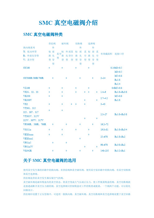
1.5SMCJ14A中文资料
- 格式:pdf
- 大小:188.16 KB
- 文档页数:3


SMC材料2009年03月05日星期四02:27SMC复合材料(片状模塑料)经高温一次模压成型,具有机械强度高、材料重量轻、耐腐蚀、使用寿命长,绝缘强度高、耐电弧、阻燃、密封性能好,且产品设计灵活,易规模化生产,并有安全美观的优点,具有全天候防护功能,能够满足室外工程项目中各种恶劣环境和场所的需要,克服了室外金属设备箱体的易锈蚀、寿命短和隔热保温性能差等缺陷,广泛应用于电信、电力和铁路等领域。
一、SMC绝缘板(不饱和聚酯玻璃纤维增强模塑料)SMC绝缘板采用不饱和聚酯片状模塑塑料压制而成,具有色泽均匀、耐电弧、FV0阻燃,吸水率低、耐漏电性好、尺寸公差稳定、翘曲小、介电强度及耐电压高。
用于高低压开关柜的各种绝缘板及结构件。
SMC板材为1000mm*2000mm SMC绝缘板材料已通过ROHS环保检测和桂林高压所检测,目前我公司已与西门子,施耐德,东芝白云,森源电气等开关厂合作,为电气行业提供合格的产品。
二、SMC的应用领域电工电气行业:各种开关柜的隔板、衬板、绝缘支座、支架、灭弧罩、灭弧筒及各类型的绝缘子、灭弧片、触头座、母线夹板及电机出线端子盒、电表箱等。
汽车行业:汽车保险杠、挡泥板、备胎仓、坐椅、仪表盘、防眩板等。
建筑行业:各种建筑物高层水箱、卫生间洁具、装饰板和其它产品。
铁路行业:信号灯、车厢窗框、信号盒外壳等。
SMC系列模塑料性能指标(JB7770-1995标准)BMC系列模塑料性能指标(JB7770-1995标准)SMC材料在模压汽车配件行业特点及优势字体大小:大- 中- 小gqgmzhang发表于09-06-25 12:13 阅读(88) 评论(0)一、重量轻对于相同的部件,使用SMC复合材料制作后重量较之钢材轻20-30%,满足了汽车领域要求在保证部件强度的情况下减轻部件重量的要求,是汽车工业节能的理想产品。
另采用SMC部件不仅节省汕耗、节省能源,也有利于环境的改善。
二、物理性能优异其物理性能指标最能与金属材料抗衡,而且在高温条件下仍能保持机械性能,是一般热塑性塑料不可比拟的,是以塑代钢的理想材料。


Instruction ManualSpace Saving Vacuum UnitSeries ZQ□AThe intended use of the vacuum unit is to generate vacuum and controlthe operation of suction and release.These safety instructions are intended to prevent hazardous situations and/or equipment damage. These instructions indicate the level of potential hazard with the labels of “Caution,” “Warning” or “Danger.”They are all important notes for safety and must be followed in additionto International Standards (ISO/IEC) *1), and other safety regulations.*1) ISO 4414: Pneumatic fluid power - General rules relating to systems.ISO 4413: Hydraulic fluid power - General rules relating to systems.IEC 60204-1: Safety of machinery - Electrical equipment of machines. (Part 1: General requirements)ISO 10218-1: Manipulating industrial robots -Safety. etc.•Refer to product catalogue, Operation Manual and Handling Precautions for SMC Products for additional information.• Keep this manual in a safe place for future reference.Warning•Always ensure compliance with relevant safety laws and standards.•All work must be carried out in a safe manner by a qualified person in compliance with applicable national regulations. 2 SpecificationsNote *1) 10 to 150 Hz for 2 hours in each direction of X, Y and Z (De-energized, Initial valve).Note *2) 3 times in each direction of X, Y and Z (De-energized, Initial valve).measurement standards. They depend on atmospheric pressure (weather, altitude, etc.) and measurement method.Note *2) Must be 0.05MPa or more, lower than P Port pressure.Port Types: P: Air supply port, PD: Vacuum release port, PV: Common vacuum supply pressure port, PS: Common pilot pressure supply portNote *1) When needle is fully open.Note *2) Must be 0.05MPa or more, lower than PS Port pressure.3 Installation3.1 InstallationWarning•Do not install the product unless the safety instructions have been readand understood.•When mounting the product, tighten it with the recommendedtightening torque (0.54 to 0.66 N•m).•When mounting the manifold product, use the attached washers.•When installing the product, secure the space required formaintenance and inspection of the product•Do not drop, hit, or apply excessive impact to the product. 3.2 EnvironmentWarning•Do not use in an environment where corrosive gases, chemicals, salt water or steam are present.•Do not use in an explosive atmosphere.•Do not expose to direct sunlight. Use a suitable protective cover. •Do not install in a location subject to vibration or impact in excess of the product’s specifications.•Do not mount in a location exposed to radiant heat that would result in temperatures in excess of the product’s specifications•The suction filter used in this product is a simple one. If there is a lot of dust in the usage environment, please consider using a suction filter (ZFC series, etc.).•Do not use in place where static electricity build-up can occur.•Do not use in an environment where surges occur.3.3 Air SupplyCaution•Do not use air containing chemicals, synthetic oils containing organic solvents, salts, or corrosive gases.•Recommended quality of the supplied air be equivalent to the compressed air cleanliness grade "2: 6: 3" according to ISO8573-1: 2010.•Do not supply the pressure in excess of the product’s specificatio ns.3.4 PipingCaution•Before connecting piping make sure to clean up chips, cutting oil, dust, etc.•When piping pipe fittings to the pilot pressure exhaust (PE) port (M3) of the single specification, fix the parts where the port is installed, tighten by hand, and then use an appropriate tool to make about 1/4 turn. (Recommended tightening torque: 0.4 to 0.5 Nm)•When piping pipe fittings to the pilot pressure exhaust (P) port, etc. (M5) of the single specification, fix the parts where the port is installed, tighten by hand, and then use an appropriate tool to make about 1/6 to1/4 turn. (Recommended tightening torque: 1.0 to 1.5 Nm)•When piping the tube to the one-touch fitting, grasp the tube, slowly insert it into the one-touch fitting, and insert it all the way in. After inserting it all the way, pull the tube lightly and check that it does not come off.3.5 Wiring to the solenoid valve and pressure switchesRefer to the operation manual of solenoid valve (V100 series) and pressure switch (ZSE10 series). Manuals can be found by the links below:ZSE10: https:///manual/en-jp/?k=zse10V100: https:///manual/en-jp/?k=V1004 Settings4.1 Manual Override (With supply valve and release valve)Refer to the operation manual of the solenoid valve V100 series for the manual operation method.ORIGINAL INSTRUCTIONSManifoldSingle UnitManual of supply valveManual of release valve4.2 Release flow adjusting needleWhen the release valve is turned on, vacuum release air is let out.The release flow adjusting needle allows to control the vacuum break air flow rate.Loosen the lock nut and use a flat-blade screwdriver to adjust the release flow rate adjustment needle at the back of the lock nut.The breaking flow rate adjustment needle can be turned clockwise to reduce the release flow rate, and counterclockwise to increase the release flow rate.After adjusting the release flow rate adjustment needle, tighten the lock nut to fix the adjustment position.Refer to the catalogue for ‘How to Order’.Refer to the catalogue for outline dimensions.7.1 General MaintenanceCaution•Not following proper maintenance procedures could cause the product to malfunction and lead to equipment damage.• If handled improperly, compressed air can be dangerous.• Maintenanceofpneumatic systems should be performed only by qualified personnel.• Before performing maintenance, turn off the power supply and be sure to cut off the supplypressure. Confirm thattheair is released toatmosphere.• After installation and maintenance, apply operating pressure and power to the equipment and perform appropriate functional and leakage tests to make sure the equipment is installed correctly.• If any electrical connections are disturbed during maintenance, ensure they are reconnected correctly, and safety checks are carried out as required to ensure continued compliance with applicable national regulations.• Do not make any modification to the product.• Do not disassemble the product, unless required by installation or maintenance instructions • Implement the maintenance and check shown below to use the space saving vacuum unit safely and in an appropriate way for a long period of time.• Drain the air filter and mist separator regularly• Replace the sound absorbing material (silencer) built into the ejector regularly• Refer to the online operation manual for replacement parts. • Do not use benzene or thinner for cleaning7.2 Sound absorbing material replacement method • Single Unit− Loosen the assembly screws (2 pieces) of the silencer plate and remove the silencer plate (2 pieces) and the sound absorbing material.− Replace the silencer plate (2 sheets) and the sound absorbing material.− Assemble the silencer plate with the assembly screws (recommended tightening torque: 0.028 to 0.032 Nm).• Manifold− Loosen the two assembly screws of the silencer block and remove the silencer block.− Replace the sound absorbing material built into the silencer block. − Assemble the silencer block with the assembly screws (recommended tightening torque: 0.25 to 0.31 Nm).7.3 Filter element replacement method• Loosen the tension bolt and remove the filter case. • Replace the filter element built into the filter case.• Assemble the filter case with tension bolts (recommended tightening torque: 0.12 to 0.18 Nm).8.1 Limited warranty and Disclaimer/Compliance Requirements Refer to Handling Precautions for SMC Products.Caution• Exhaust from Space saving vacuum unit (ejector system)− For the silencer exhaust type, make sure that there is no obstruction around the exhaust port.− In the case of port exhaust type, exhaust resistance may be affected depending on the pipe diameter and length, so make sure that the back pressure is 1 kPa or less.− Do not block the exhaust port. • Ejector exhaust noiseWhen the vacuum ejector generates a vacuum, an intermittent noise (abnormal noise) may be generated from the exhaust section near the standard supply pressure where the vacuum pressure peaks, and the vacuum pressure may not be constant. There is no problem in use as long as the vacuum pressure range is sufficient for adsorption, but if you are concerned about the sound or affect the setting of the pressure switch, slightly change the supply pressure and reduce the range of the intermittent sound. Please avoid it.• About the release flow rate adjusting needle− Leakage cannot be reduced to zero when the needle is fully closed. − Since the release flow rate adjustment needle has a retaining mechanism, it will not rotate beyond the rotation stop position. If you try to turn the needle any further, it may be damaged.− When tightening the lock nut, tighten it by hand to about 15 to 30 degrees, and be careful not to damage it due to overtightening. • About solenoid valve and pressure switchFor the solenoid valve (V100 series) and pressure switch (ZSE10 series), refer to each instruction manual.9 Product disposalThis product should not be disposed of as municipal waste. Check your local regulations and guidelines to dispose this product correctly, in order to reduce the impact on human health and the environment.10 ContactsRefer to or www.smc.eu for your local distributor/importer.URL : https:// (Global) https:// www.smc.eu (Europe) SMC Corporation, 4-14-1, Sotokanda, Chiyoda-ku, Tokyo 101-0021, JapanSpecifications are subject to change without prior notice from the manufacturer. © 2021 SMC Corporation All Rights Reserved. Template DKP50047-F-085MTension bolt Filter case Filter element。


Other SettingsSummary of Product partsSimple Setting ModeTroubleshootingNote: Specifications are subject to change without prior notice and any obligation on the part of the manufacturer.© 2015 SMC Corporation All Rights ReservedAkihabara UDX 15F, 4-14-1, Sotokanda, Chiyoda-ku, Tokyo 101-0021, JAPANPhone: +81 3-5207-8249 Fax: +81 3-5298-5362URL Specifications/Outline with Dimensions (in mm)Refer to the product catalogue or SMC website (URL ) formore information about the product specifications and outline dimensions.PS※※-OMS0008-A InstallationMounting with bracketMount the bracket to the body with mounting screws (Self tapping screws:Nominal size 3 x 8L (2 pcs)), then set the body to the specified position.∗: Tighten the bracket mounting screws to a torque of 0.5±0.05 Nm.Self tapping screws are used, and should not be re-used several times.∗: The panel mount adapter can be rotated through 90 degrees for mounting.•Bracket A (Part No.: ZS-46-A1)•Bracket B (Part No.: ZS-46-A2)Mounting with panel mount adapterMount part (a) to the front of the body and fix it. Then insert the body with (a)into the panel until (a) comes into contact with the panel front surface. Next,WiringWiring connectionsConnections should be made with the power supply turned off.Use a separate route for the product wiring and any power or high voltagewiring. Otherwise, malfunction may result due to noise.If a commercially available switching power supply is used, be sure toground the frame ground (FG) terminal. If the switching power supply isconnected for use, switching noise will be superimposed and it will not beable to meet the product specifications. In that case, insert a noise filtersuch as a line noise filter/ferrite between the switching power supplies orchange the switching power supply to the series power supply.How to use connectorstraight out.OUT1NCNCDC(-)PipingTightening the connection threadFor connecting to the body (piping specification: -M5)After hand tightening, apply a spanner of the correctsize to the spanner flats of the piping body, and tightenwith a 1/6 to 1/4 rotation.As a reference, the tightening torque is 1 to 1.5 Nm.(When replacing the piping adapter ZS-39-N∗, tighten itusing the same method.)Piping specification: -01, -N01After hand tightening, hold the hexagonal spanner flatsof the pressure port with a spanner, and tighten with 2 to3 rotations.As a reference, the tightening torque is 3 to 5 Nm.When tightening, do not hold the Z/ISE20 body with aspanner.Default settingsWhen the pressure exceedsthe set value, the switch will beturned on. When the pressurefalls below the set value by theamount of hysteresis or more,the switch will be turned off.The default setting is to turn onthe pressure switch when thepressure reaches the centre of the atmospheric pressure and upper limit of therated pressure range. If this condition, shown to the right, is acceptable, then keepthese settings.Error indication functionThis function is to display error location and content when a problem or error has occurred.than above are displayed, please contact SMC.Refer to the SMC website (URL ) for more informationabout troubleshooting.button between1 and 3 sec.button between3 and 5 sec.∗:The outputs will continue to operate during setting.∗:If a button operation is not performed for 3 seconds during the setting, the display will flash.(This is to prevent the setting from remaining incomplete if, for instance, an operator were to leaveduring setting.)∗:3 step setting mode, simple setting mode and function selection mode settings are reflected eachother.[3 step setting mode (hysteresis mode)]orsetting can be changed in the same way.button once when the item toThe set value on the sub display (right) willstart flashing.orbutton and can be reduced withbutton.buttons are pressed and held simultaneously for 1second or longer, the set value is displayed as [- - -], and the set value will bethe same as the current pressure value automatically (snap shot function).button.button to complete the setting.The Pressure switch turns on within a set pressure range (from P1L to P1H) duringwindow comparator mode.Set P1L, the lower limit of the switch operation, and P1H, the upper limit of theswitch operation and WH1 (hysteresis) following the instructions given above.(When reversed output is selected, the sub display (left) shows [n1L] and [n1H].)∗:Setting of the normal/reverse output switching and hysteresis/window comparator modeswitching are performed with the function selection mode [F 1] OUT1 setting.valuePeak/bottom value indicationbutton inmeasurement mode.Snap shot functionbuttons for 1second or longer simultaneously. Then, the set value of the sub display (right)shows [- - -], and the values corresponding to the current pressure values areautomatically displayed.Zero-clear functionbuttons are pressed for 1 secondor longer simultaneously, the main display shows [- - -], and the reset to zero.The display returns to measurement mode automatically.Key-lock functionTo set each of these functions, refer to the SMC website(URL ) for more detailed information, or contact SMC.button between 1 and 3 seconds inmeasurement mode. [SEt] is displayed on the main display. Whenthe button is released while in the [SEt] display, the current pressurevalue is displayed on the main display, [P_1] or [n_1] is displayed onthe sub display (left), and the set value is displayed on the subdisplay (right) (Flashing).or button to set the(The snap shot function can be used.)or button to set the(The snap shot function can be used.)or button, the delay time of the switch output can be selected.button for 2 seconds or longer to complete the OUT1 setting.∗:If the button is pressed for less than 2 seconds, the setting will be returned to P_1.In the window comparator mode, set P1L, the lower limit of the switch operation,and P1H, the upper limit of the switch operation, WH1 (hysteresis) and dt1 (delaytime) following the instructions given above.(When reversed output is selected, the sub display (left) shows [n1L] and [n1H].)Function selection modebutton between 3 and 5seconds, to display [F 0]. Select todisplay the function to be changed[F]. Press and hold the buttonfor 2 seconds or longer in functionselection mode to return tomeasurement mode.∗:Some products do not have all the functions. If no function is available or selected due toconfiguration of other functions, [- - -] is displayed on the sub display (right).Names of individual partsRefer to the product catalogue or SMC website (URL )for more information about panel cut-out and mounting hole dimensions.Pressure Setting3 Step Setting Mode(URL ) for more detailed information, or contact SMC.MaintenanceHow to reset the product after a power cut or forcible de-energizingThe setting of the product will be retained as it was before a power cut orde-energizing. The output condition is also basically recovered to that before apower cut or de-energizing, but may change depending on the operatingenvironment. Therefore, check the safety of the whole installation before operatingthe product. If the installation is using accurate control, wait until the product haswarmed up (approximately 10 to 15 minutes).Safety InstructionsBefore UseDigital Pressure SwitchZSE20(F)/ISE20Thank you for purchasing an SMC ZSE20(F)/ISE20 Series Digital PressureSwitch.Please read this manual carefully before operating the product and make sure youunderstand its capabilities and limitations. Please keep this manual handy forfuture reference.Safety InstructionsThese safety instructions are intended to prevent hazardous situations and/orequipment damage.These instructions indicate the level of potential hazard with the labels of"Caution", "Warning" or "Danger". They are all important notes for safety and mustbe followed in addition to International standards (ISO/IEC) and other safetyregulations.OperatorSwitch ONAt normal output Switch OFFSet valueP_1HysteresisH_1TimePressureOther parameter settingsDefault settingThe default setting is as follows.If no problem is caused by thissetting, keep these settings.。


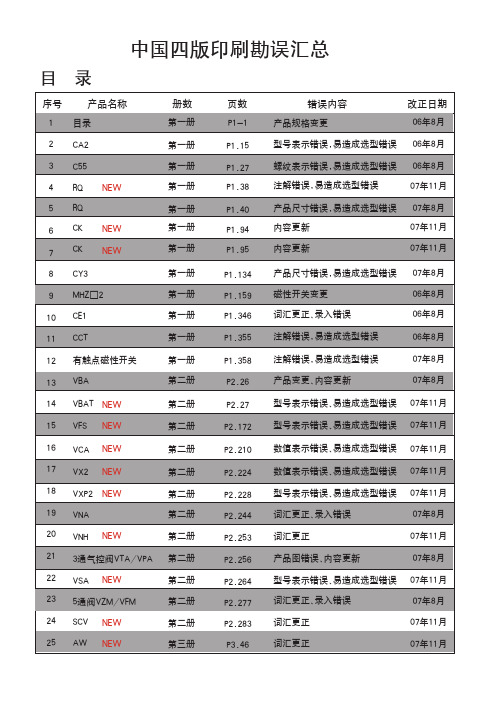
Surface Mount T RANS Z ORB ®Transient Voltage SuppressorsV (BR)Unidirectional6.8 to 540VV (BR)Bidirectional6.8 to 220VPeak Pulse Power 1500WDevices for Bidirectional ApplicationsFor bi-directional devices, use suffix CA (e.g. 1.5SMC10CA). Electrical characteristics apply in both directions.Maximum Ratings & Thermal CharacteristicsRatings at 25°C ambient temperature unless otherwise specified.ParameterSymbol Value Unit Peak power dissipation with a 10/1000µs waveform (1)(2)(Fig. 1)P PPM 1500W Peak pulse current with a 10/1000µs waveform (1) (Fig. 3)I PPM See Next TableAPower dissipation on infinite heatsink, T A = 50°C P M(AV) 6.5W Peak forward surge current 8.3ms single half sine-wave I FSM 200A uni-directional only (2)Thermal resistance junction to ambient air (3)R θJA 75°C/W Thermal resistance junction to leadsR θJL 15°C/W Operating junction and storage temperature rangeT J , T STG–65 to +150°CNotes:(1) Non-repetitive current pulse, per Fig.3 and derated above T A = 25°C per Fig. 2(2) Mounted on 0.31 x 0.31” (8.0 x 8.0mm) copper pads to each terminal (3) Mounted on minimum recommended pad layoutFeatures• Low profile package with built-in strain relief for surface mounted applications • Glass passivated junction• Low incremental surge resistance • Low inductance• Excellent clamping capability• 1500W peak pulse power capability with a 10/1000µs waveform, repetition rate (duty cycle): 0.01%• Very fast response time• Plastic package has Underwriters Laboratory Flammability Classification 94V-0Mechanical DataCase:JEDEC DO-214AB (SMC) molded plastic over passivated junctionTerminals:Solder plated, solderable per MIL-STD-750,Method 2026. High temperature soldering: 250°C/10seconds at terminals.Polarity:For uni-directional types the band denotes the cathode, which is positive with respect to the anode under normal TVS operation.Standard Packaging:16mm tape (EIA STD RS-481)Weight:0.007 oz., 0.21 gPackaging Codes – Options (Antistatic):51 – 1K per Bulk box, 10K/carton57 – 850 per 7" plastic Reel (16mm tape), 8.5K/carton 9A – 3.5K per 13" plastic Reel (16mm tape), 35K/cartonMounting Pad LayoutE x t e n d e d Vo l t a g e R a n g e 1.5SMC SeriesVishay Semiconductorsformerly General SemiconductorDocument Number Electrical Characteristics Ratings at 25°C ambient temperature unless otherwise specified. VF= 3.5V at I F = 100A (uni-directional only)Breakdown VoltageMaximum Maximum Maximum Maximum GeneralDevice MarkingV (BR) at I T (1)Test Stand-off Reverse Peak Pulse Clamping Temp.Semiconductor Code (V)Current Voltage Leakage Current Voltage at Coefficient Part Number I T V WM at V WM I PPM (2)I PPM of V (BR)UNI BI MIN MAX (mA)(V)I D (4) (µA)(A)V C (V)(% / °C)1.5SMC6.8A 6V8A 6V8C 6.457.1410 5.80100014310.50.0571.5SMC7.5A 7V5A 7V5C 7.137.8810 6.4050013311.30.0611.5SMC8.2A 8V2A 8V2C 7.798.61107.022*******.10.0651.5SMC9.1A 9V1A 9V1C 8.659.55 1.07.785011213.40.0681.5SMC10A 10A 10C 9.5010.5 1.08.551010314.50.0731.5SMC11A 11A 11C 10.511.6 1.09.40 5.096.215.60.0751.5SMC12A 12A 12C 11.412.6 1.010.2 5.089.816.70.0781.5SMC13A 13A 13C 12.413.7 1.011.1 5.082.418.20.0811.5SMC15A 15A 15C 14.315.8 1.012.8 1.070.821.20.0841.5SMC16A 16A 16C 15.216.8 1.013.6 1.066.722.50.0861.5SMC18A 18A 18C 17.118.9 1.015.3 1.059.525.20.0891.5SMC20A 20A 20C 19.021.0 1.017.1 1.054.227.70.0901.5SMC22A 22A 22C 20.923.1 1.018.8 1.049.030.60.0921.5SMC24A 24A 24C 22.825.2 1.020.5 1.045.233.20.091.5SMC27A 27A 27C 25.728.4 1.023.1 1.040.037.50.0961.5SMC30A 30A 30C 28.531.5 1.025.6 1.036.241.40.0971.5SMC33A 33A 33C 31.434.7 1.028.2 1.032.845.70.0981.5SMC36A 36A 36C 34.237.8 1.030.8 1.030.149.90.0991.5SMC39A 39A 39C 37.141.0 1.033.3 1.027.853.90.1001.5SMC43A 43A 43C 40.945.2 1.036.8 1.025.359.30.1011.5SMC47A 47A 47C 44.749.4 1.040.2 1.023.164.80.1011.5SMC51A 51A 51C 48.553.6 1.043.6 1.021.470.10.1021.5SMC56A 56A 56C 53.258.8 1.047.8 1.019.577.00.1031.5SMC62A 62A 62C 58.965.1 1.053.0 1.017.685.00.1041.5SMC68A 68A 68C 64.671.4 1.058.1 1.016.392.00.1041.5SMC75A 75A 75C 71.378.8 1.064.1 1.014.61040.1051.5SMC82A 82A 82C 77.986.1 1.070.1 1.013.31130.1051.5SMC91A 91A 91C 86.595.5 1.077.8 1.012.01250.1061.5SMC100A 100A 100C 95.0105 1.085.5 1.010.91370.1061.5SMC110A 110A 110C 105116 1.094.0 1.09.91520.1071.5SMC120A 120A 120C 114126 1.0102 1.09.11650.1071.5SMC130A 130A 130C 124137 1.0111 1.08.41790.1071.5SMC150A 150A 150C 143158 1.0128 1.07.22070.1061.5SMC160A 160A 160C 152168 1.0136 1.0 6.82190.1081.5SMC170A 170A 170C 162179 1.0145 1.0 6.42340.1081.5SMC180A 180A 180C 171189 1.0154 1.0 6.12460.1081.5SMC200A 200A 200C 190210 1.0171 1.0 5.52740.1081.5SMC220A 220A 220C 209231 1.0185 1.0 4.63280.1081.5SMC250A 250A —237263 1.0214 1.0 4.43440.1101.5SMC300A 300A —285315 1.0256 1.0 3.64140.1101.5SMC350A 350A —333368 1.0300 1.0 3.14820.1101.5SMC400A 400A —380420 1.0342 1.0 2.75480.1101.5SMC440A 440A —418462 1.0376 1.0 2.56020.1101.5SMC480A 480A —456504 1.0408 1.0 2.286580.1101.5SMC510A 510A —485535 1.0434 1.0 2.156980.1101.5SMC540A540A—5135671.04591.02.037400.110Notes: (1) Pulse test: t p ≤50ms(2) Surge current waveform per Fig. 3 and derate per Fig. 2(3) All terms and symbols are consistent with ANSI/IEEE CA62.35(4) For bidirectional types with V R 10 volts and less, the I D limit is doubled1.5SMC SeriesVishay Semiconductorsformerly General Semiconductor Document Number 88303101100400V WM — Reverse Stand-Off Voltage (V)Fig. 2 – Pulse Derating CurveP P P M — P e a k P u l s e P o w e r (k W )Fig. 1 – Peak Pulse Power Rating CurveFig. 6 - Maximum Non-Repetitive Forward Surge Current Uni-Directional Use Only11010010100200P e a k F o r w a r d S u r g e C u r r e n t , A m p e r e sNumber of Cycles at 60Hzt p — Pulse Duration (sec)T r a n s i e n t T h e r m a l I m p e d a n c e (°C /W )Fig. 5 – Typical Transient ThermalImpedance0.11.0101000.0010.010.11101001000I P P M — P e a k P u l s e C u r r e n t , % I R S M1.02.03.04.0t — Time (ms)Ratings andCharacteristic Curves (T A = 25°C unless otherwise noted)1.5SMC SeriesVishay Semiconductorsformerly General SemiconductorDocument Number 。

Surface Mount T RANS Z ORB ®Transient Voltage SuppressorsV (BR)Unidirectional6.8 to 540VV (BR)Bidirectional6.8 to 220VPeak Pulse Power 1500WDevices for Bidirectional ApplicationsFor bi-directional devices, use suffix CA (e.g. 1.5SMC10CA). Electrical characteristics apply in both directions.Maximum Ratings & Thermal CharacteristicsRatings at 25°C ambient temperature unless otherwise specified.ParameterSymbol Value Unit Peak power dissipation with a 10/1000µs waveform (1)(2)(Fig. 1)P PPM 1500W Peak pulse current with a 10/1000µs waveform (1) (Fig. 3)I PPM See Next TableAPower dissipation on infinite heatsink, T A = 50°C P M(AV) 6.5W Peak forward surge current 8.3ms single half sine-wave I FSM 200A uni-directional only (2)Thermal resistance junction to ambient air (3)R θJA 75°C/W Thermal resistance junction to leadsR θJL 15°C/W Operating junction and storage temperature rangeT J , T STG–65 to +150°CNotes:(1) Non-repetitive current pulse, per Fig.3 and derated above T A = 25°C per Fig. 2(2) Mounted on 0.31 x 0.31” (8.0 x 8.0mm) copper pads to each terminal (3) Mounted on minimum recommended pad layoutFeatures• Low profile package with built-in strain relief for surface mounted applications • Glass passivated junction• Low incremental surge resistance • Low inductance• Excellent clamping capability• 1500W peak pulse power capability with a 10/1000µs waveform, repetition rate (duty cycle): 0.01%• Very fast response time• Plastic package has Underwriters Laboratory Flammability Classification 94V-0Mechanical DataCase:JEDEC DO-214AB (SMC) molded plastic over passivated junctionTerminals:Solder plated, solderable per MIL-STD-750,Method 2026. High temperature soldering: 250°C/10seconds at terminals.Polarity:For uni-directional types the band denotes the cathode, which is positive with respect to the anode under normal TVS operation.Standard Packaging:16mm tape (EIA STD RS-481)Weight:0.007 oz., 0.21 gPackaging Codes – Options (Antistatic):51 – 1K per Bulk box, 10K/carton57 – 850 per 7" plastic Reel (16mm tape), 8.5K/carton 9A – 3.5K per 13" plastic Reel (16mm tape), 35K/cartonMounting Pad LayoutE x t e n d e d Vo l t a g e R a n g e 1.5SMC SeriesVishay Semiconductorsformerly General SemiconductorDocument Number Electrical Characteristics Ratings at 25°C ambient temperature unless otherwise specified. VF= 3.5V at I F = 100A (uni-directional only)Breakdown VoltageMaximum Maximum Maximum Maximum GeneralDevice MarkingV (BR) at I T (1)Test Stand-off Reverse Peak Pulse Clamping Temp.Semiconductor Code (V)Current Voltage Leakage Current Voltage at Coefficient Part Number I T V WM at V WM I PPM (2)I PPM of V (BR)UNI BI MIN MAX (mA)(V)I D (4) (µA)(A)V C (V)(% / °C)1.5SMC6.8A 6V8A 6V8C 6.457.1410 5.80100014310.50.0571.5SMC7.5A 7V5A 7V5C 7.137.8810 6.4050013311.30.0611.5SMC8.2A 8V2A 8V2C 7.798.61107.022*******.10.0651.5SMC9.1A 9V1A 9V1C 8.659.55 1.07.785011213.40.0681.5SMC10A 10A 10C 9.5010.5 1.08.551010314.50.0731.5SMC11A 11A 11C 10.511.6 1.09.40 5.096.215.60.0751.5SMC12A 12A 12C 11.412.6 1.010.2 5.089.816.70.0781.5SMC13A 13A 13C 12.413.7 1.011.1 5.082.418.20.0811.5SMC15A 15A 15C 14.315.8 1.012.8 1.070.821.20.0841.5SMC16A 16A 16C 15.216.8 1.013.6 1.066.722.50.0861.5SMC18A 18A 18C 17.118.9 1.015.3 1.059.525.20.0891.5SMC20A 20A 20C 19.021.0 1.017.1 1.054.227.70.0901.5SMC22A 22A 22C 20.923.1 1.018.8 1.049.030.60.0921.5SMC24A 24A 24C 22.825.2 1.020.5 1.045.233.20.091.5SMC27A 27A 27C 25.728.4 1.023.1 1.040.037.50.0961.5SMC30A 30A 30C 28.531.5 1.025.6 1.036.241.40.0971.5SMC33A 33A 33C 31.434.7 1.028.2 1.032.845.70.0981.5SMC36A 36A 36C 34.237.8 1.030.8 1.030.149.90.0991.5SMC39A 39A 39C 37.141.0 1.033.3 1.027.853.90.1001.5SMC43A 43A 43C 40.945.2 1.036.8 1.025.359.30.1011.5SMC47A 47A 47C 44.749.4 1.040.2 1.023.164.80.1011.5SMC51A 51A 51C 48.553.6 1.043.6 1.021.470.10.1021.5SMC56A 56A 56C 53.258.8 1.047.8 1.019.577.00.1031.5SMC62A 62A 62C 58.965.1 1.053.0 1.017.685.00.1041.5SMC68A 68A 68C 64.671.4 1.058.1 1.016.392.00.1041.5SMC75A 75A 75C 71.378.8 1.064.1 1.014.61040.1051.5SMC82A 82A 82C 77.986.1 1.070.1 1.013.31130.1051.5SMC91A 91A 91C 86.595.5 1.077.8 1.012.01250.1061.5SMC100A 100A 100C 95.0105 1.085.5 1.010.91370.1061.5SMC110A 110A 110C 105116 1.094.0 1.09.91520.1071.5SMC120A 120A 120C 114126 1.0102 1.09.11650.1071.5SMC130A 130A 130C 124137 1.0111 1.08.41790.1071.5SMC150A 150A 150C 143158 1.0128 1.07.22070.1061.5SMC160A 160A 160C 152168 1.0136 1.0 6.82190.1081.5SMC170A 170A 170C 162179 1.0145 1.0 6.42340.1081.5SMC180A 180A 180C 171189 1.0154 1.0 6.12460.1081.5SMC200A 200A 200C 190210 1.0171 1.0 5.52740.1081.5SMC220A 220A 220C 209231 1.0185 1.0 4.63280.1081.5SMC250A 250A —237263 1.0214 1.0 4.43440.1101.5SMC300A 300A —285315 1.0256 1.0 3.64140.1101.5SMC350A 350A —333368 1.0300 1.0 3.14820.1101.5SMC400A 400A —380420 1.0342 1.0 2.75480.1101.5SMC440A 440A —418462 1.0376 1.0 2.56020.1101.5SMC480A 480A —456504 1.0408 1.0 2.286580.1101.5SMC510A 510A —485535 1.0434 1.0 2.156980.1101.5SMC540A540A—5135671.04591.02.037400.110Notes: (1) Pulse test: t p ≤50ms(2) Surge current waveform per Fig. 3 and derate per Fig. 2(3) All terms and symbols are consistent with ANSI/IEEE CA62.35(4) For bidirectional types with V R 10 volts and less, the I D limit is doubled1.5SMC SeriesVishay Semiconductorsformerly General Semiconductor Document Number 88303101100400V WM — Reverse Stand-Off Voltage (V)Fig. 2 – Pulse Derating CurveP P P M — P e a k P u l s e P o w e r (k W )Fig. 1 – Peak Pulse Power Rating CurveFig. 6 - Maximum Non-Repetitive Forward Surge Current Uni-Directional Use Only11010010100200P e a k F o r w a r d S u r g e C u r r e n t , A m p e r e sNumber of Cycles at 60Hzt p — Pulse Duration (sec)T r a n s i e n t T h e r m a l I m p e d a n c e (°C /W )Fig. 5 – Typical Transient ThermalImpedance0.11.0101000.0010.010.11101001000I P P M — P e a k P u l s e C u r r e n t , % I R S M1.02.03.04.0t — Time (ms)Ratings andCharacteristic Curves (T A = 25°C unless otherwise noted)1.5SMC SeriesVishay Semiconductorsformerly General SemiconductorDocument Number 。