液体粘性调速离合器
- 格式:doc
- 大小:115.50 KB
- 文档页数:12


交流风机调速原理交流风机作为工业领域中的重要设备,对其调速原理的了解和应用具有重要的实际意义。
本文将主要从电磁调速、液力耦合器调速、齿轮减速器调速、变频调速、变极调速、滑差调速、液粘调速等方面阐述交流风机的调速原理。
1.电磁调速电磁调速是一种通过电磁感应原理实现交流风机调速的方法。
其主要部件包括电磁调速控制器、电磁离合器和电动机。
电磁调速控制器通过调节电磁离合器的励磁电流,改变电磁离合器的转矩,从而控制电动机的转速。
2.液力耦合器调速液力耦合器调速的原理是利用工作液在泵轮和涡轮之间的流动来传递动力,通过调节泵轮和涡轮之间的液力阻力来实现调速。
其主要部件包括液力耦合器和谐波减速器。
液力耦合器通过改变泵轮和涡轮之间的液力阻力来调节转速,谐波减速器则用于降低转速并增加转矩。
3.齿轮减速器调速齿轮减速器调速的原理是将电动机的高转速转化为低转速,并通过齿轮传动将动力传递给风机。
其主要部件包括齿轮减速器和电动机。
齿轮减速器通过改变齿轮比来降低电动机的转速,从而实现对风机的调速。
4.变频调速变频调速的原理是改变电源频率,从而改变电动机的转速。
其主要部件包括变频器和电动机。
变频器通过改变电源频率来调节电动机的转速,实现风机的调速。
5.变极调速变极调速的原理是通过改变电动机的极数来实现调速。
其主要部件包括定子绕组和电动机。
定子绕组的变化和调节可以实现电动机极数的改变,从而改变电动机的转速,实现对风机的调速。
6.滑差调速滑差调速的原理是利用滑差离合器来实现调速。
其主要部件包括滑差离合器和电动机。
滑差离合器通过与电动机的输出轴连接,通过改变滑差离合器的滑差率来调节电动机的转速,实现风机的调速。
7.液粘调速液粘调速的原理是利用液粘离合器来实现调速。
其主要部件包括液粘离合器和电动机。
液粘离合器通过与电动机的输出轴连接,通过改变离合器中液体粘度来调节电动机的转速,实现风机的调速。
综上所述,交流风机调速原理根据不同需求和场合,可采用不同的调速方法。


可控启动传输装置CST在带式输送机上的应用对于大型带式输送机,其对驱动系统的要求主要体现在启动、制动过程中能最大限度的降低系统的惯性力,并能实现过载保护和负载平衡,将带式输送机的加速、停车和运行时的胶带张力减到最小。
可控启动传动装置CST的性能完全满足这些要求,使大型带式输送机的性能达到最好。
而由传统的电动机、减速器所组成的驱动装置在启动和停车过程当中输送带的带速随着电动机的转速变化而快速变化,加剧了输送机本身的振动,增大了系统的惯性力,特别是在输送带满载情况下启动更为困难,因此传统的驱动系统已经不能满足长距离、大运量的大型带式输送机需求。
在阳煤集团最早使用可控CST启动装置的时间是1997年投产的新景矿主斜井皮带,在2005年3月投入使用的新景矿芦南二区皮带,在2006年12月投入使用的新元公司主斜井皮带和集中胶带巷皮带,均安装使用了CST启动装置,使用状况良好。
1、CST装置概述:CST是一种新型机电一体化产品,它由多级齿轮减速器、湿式线形离合器、液压控制系统组成。
它是专门为平滑启动运送大惯性载荷,如长距离、大运量的皮带输送机而设计的。
CST的输出扭矩由液压控制系统控制,它随着离合器上所加的液压压力而变化。
一条皮带可以由一台电动机及一台CST驱动,也可以由多台电动机及多台CST驱动。
驱动电动机在皮带机启动之前,此时CST的输出轴保持不动,当驱动电动机达到满转速时,控制系统逐渐增加每台CST离合器上的液压压力,启动皮带机并逐渐加速到满速度。
这使得皮带机在被加速至满速度之前有一个缓慢而均匀的预拉伸过程。
加速时间可以根据需要在规定范围内进行调整。
启动驱动电动机可以按顺序空载启动,所以电动机的冲击电流非常小。
由于驱动电动机可以根据运行负载进行选择而不必根据启动负载选择,所以CST驱动系统可以选用功率较小的电动机。
同样CST也可以象控制皮带机的启动那样控制皮带机的停车,通过延长停车时间可以降低对胶带的动态冲击力。

黄河科技学院毕业设计(论文)文献综述第 1 页文献综述摘要:奥米伽离合器的发展、原理、应用关键词:奥米伽离合器、滑差离合器、磨擦片奥米伽离合器(YNTL型调速离合器),它是一种新型的可控无级调速传动装置,俗称滑差离合器或液体粘性传动。
1 奥米伽离合器的发展奥米伽离合器是以粘性流体作为价质的温式磨擦离合器,它可以实现无级变速,又能实理完全离合的功能,故奥米伽离合器具备无级调速器与磨擦离合器的功能和优点。
随着工农业的发展,能源的消耗量日益增大,而能源的总贮量又有一定的限制。
因此,能源问题是世界上人类所面临的主要问题,据上海市一项调查报告材料表明,全市功率在55KW以上的风机和水泵约有35000台,合计装机总量约为124万千瓦,每年耗电45亿度电,相当于该市工业用电的40%,如炼钢转炉用的排烟风机、高炉炼铁用的环保除尘风机、发电厂用的锅炉给水泵、管道输油泵站的油泵等,而一般讲像风机、泵机所需的风量、水量、油量需经常调节。
例如炼钢周期为24—26分钟,而吹炼时间仅14—15分钟,若全功率供风量会浪费较多的能源,若在电动机与水泵之间装上变速器,实现无级变速方式来代替节流调节,节流调速会耗去大量的能量,从而实现明显节能效益,一台25KW电机的水泵用ω调速离合器每年可节约5万度左右[13]。
奥米伽离合器是一种新型的无级变速磨擦式调速器,调速范围较大。
理论上讲从0~1任意上选取,并且奥米伽离合器同时具有可载保护,减缓冲击噪音低,运转平稳传动效益很高,控制操作方便等优点,是调速节能的理想装置。
其在1980年代,才引入我国技术上不够成熟,批量生产线更为稀有,据了解仅有北京理工大学,上海交大等极少数科研机构的一部分对其有过深入研究。
并、为国黄河科技学院毕业设计(论文)文献综述第 2 页产化做过理论工作,首批小批量生产为开封调速器厂,由于其设计思想别出心裁比变频调速成本低工作可靠等优点。
1990年,军转民高技术产品展览会上,经国防工委、国计委、科委、国家对外经贸委评审而授予金奖,该技术发明人(美国)获35届尤里卡世界发明博览会和一级骑士勋章,在八十年代处于国际先进水平[12]。
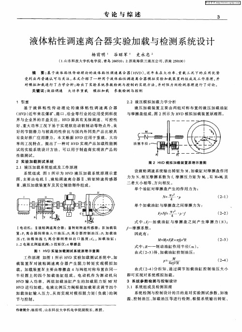
煤矿机械Coal Mine MachineryVol.34No.01Jan.2013第34卷第01期2013年01月引言液体黏性调速离合器的理论基础是液体黏性传动理论,它是基于牛顿内摩擦定律,利用液体黏性或油膜剪切力的作用来传递动力、调节速度和转矩。
它的主从动轴上分别设计有间隙可调的主从动片,充入黏度较小的润滑油作为工作液,在轴向形成许多圆盘油膜用以传递动力,通过调节主被动摩擦片间的油膜厚度,可以改变从动轴的转速。
液体黏性调速离合器中两摩擦片间油膜的流动,属于液体在密封缝隙中的运动,油膜的流动状态及流场特性对液黏调速离合器的传动性能起着重要的作用。
因此,本文利用流体分析软件CFX 和其前处理软件—ICEM CFD 相结合的数值方法对油膜进行数值模拟。
1油膜运动过程的数值模拟为了准确方便地计算和分析流体的流动情况和流动特性,取2片摩擦片之间的一层油膜为研究对象单独进行分析,不考虑温度的影响。
将动力学分析中提取出的某一时刻的角速度数据信息添加给油膜,对其进行分析。
油膜数值计算的过程如下。
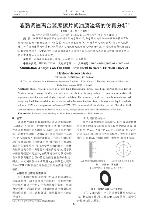
(1)几何模型的导入为便于观察油膜的流场情况,取主被动摩擦片之间填充的油液区域作为仿真模型中的流体域,建立内径123mm ,外径213mm 的环形区域,并且凸出进油口及出油口部位作为仿真模型,模型的平面图如图1,在Pro/E 中创建油膜三维模型,如图2所示。
(a )装配图中的油膜二维模型(b )单个油膜二维模型图图1油膜的二维模型1.主动摩擦片2.油膜3.被动摩擦片图2油膜的三维Pro/E 模型图将在Pro/E 软件中建立的油膜实体模型保存为“igs ”格式的文件,导入到CFD ICEM 软件。
划分后的模型如图3所示。
液黏调速离合器摩擦片间油膜流场的仿真分析*于美丽1,宋华2,付丽华2(1.营口大学园管理委员会,辽宁营口115000;2.辽宁科技大学,辽宁鞍山114051)摘要:液黏调速离合器是依据牛顿液体内摩擦定律,即摩擦片间液体的黏性和油膜的剪切作用而形成的一种新型流体传动装置,可以实现主动部分与从动负载之间的分离、接合和无级调速。


湿式离合器工作原理
湿式离合器是一种常用于汽车、摩托车等动力传动系统的离合器类型。
它的工作原理基于液体的黏性和流动性。
湿式离合器由两个主要部分组成:驱动器和从动器。
驱动器通常连接到发动机,而从动器连接到传动装置。
两个部分之间通过摩擦来传递动力。
在湿式离合器中,驱动器和从动器之间存在一个摩擦片,被称为摩擦盘。
摩擦盘由摩擦材料组成,通常是摩擦纸或摩擦片。
它有两个主要的功能:传递动力和控制离合。
当发动机运转时,离合器的压盘会向摩擦盘施加压力,使其紧密接触。
压盘由离合器的压盘机构控制,它可以通过踏板或其他操作装置来操纵。
当压盘施加足够的压力时,摩擦盘开始与驱动器的摩擦面接触。
接触面积的增加导致摩擦力的产生,这使得驱动器和从动器之间的转矩能够传递。
因为摩擦盘浸泡在润滑油中,润滑油的黏性可以提高摩擦盘的摩擦效果,并减少磨损。
当离合器踏板释放时,压力从压盘中移除,摩擦盘不再与驱动器紧密接触。
这导致摩擦盘的摩擦力降低,驱动器的转矩无法传递给从动器。
这种情况下,传动装置可以自由旋转,实现离合器的分离。
总结而言,湿式离合器的工作原理是通过润滑油的流动和摩擦
盘的摩擦来传递和控制动力传递。
液体的黏性和流动性使得湿式离合器具有更高的承载能力和耐久性。

调速型液力耦合器工作原理
调速型液力耦合器是一种基于液体流体力学原理工作的传动装置。
它由驱动轮、从动轮和液力变矩器三个主要部分组成。
当驱动轴转动时,液力变矩器中的泵轮和涡轮也开始旋转。
泵轮通过泵轮叶片将工作液体(通常是液压油)向外边发送,涡轮
则将工作液体带回液力变矩器内。
工作液体流经液力变矩器内的转子,产生液体的环流形成液体流动,从而产生扭矩效应。
液力变矩器的主要工作原理是通过分离泵轮和涡轮之间的液体,从而实现工作液体的能量转移。
当驱动轮的转速较低时,驱动轮叶片将工作液体喷出形成高速的液体流,液体流经涡轮叶片,使涡轮开始旋转,即产生输出扭矩。
当驱动轮的转速逐渐提高时,液体流动速度增加,液体的动能也增加,从而提高输出扭矩。
调速型液力耦合器的工作原理是通过调节液力变矩器内工作液体的流通量来实现变速调节。
通过改变泵轮叶片的角度,调节液体的流入量和流出量,从而改变输出轮的转速。
当调节泵轮叶片的角度较小时,液体的流通量较小,输出轮的转速较低;当调节泵轮叶片的角度较大时,液体的流通量较大,输出轮的转速较高。
通过这种方式可以灵活地调整输出轮的转速,实现传动装置的变速调节。
总之,调速型液力耦合器通过液体流动产生的液力效应,实现了输入轮和输出轮之间的扭矩传递和变速调节。
它具有结构简
单、可靠性高、变速范围广等优点,在工程机械、汽车等领域得到了广泛的应用。


hydroviscous Variable Speed Clutch (HVSC)——液体粘性调速离合器发布日期:[10-11-22 21:06:20] 浏览人次:[424 ]AbstractYL-8 hydroviscous Variable Speed Clutch (HVSC) is an energy-conservation product with high efficiency newly developed by Liaoning Huafu Petroleum High-Tech Co., Ltd (Huafu) .It has passed technical appraisal organized by Liaoning Province on July 24, 2004, and the achievement of which has reached world advanced stage.YL-symbol of HVSC;8-symbol of nominal torque, the unit of which is k N·m. YL-8 shows that the equipment can transmit torque of 8000 N·m.HVSC is a new fluid drive equipment, the principle of which is the viscosity of fluid and the shear effect of oil film, as expressed by Newton’sinternal-friction law.Characteristics:The main AC motor can be separated from or connected with working machine, and the speed can be regulated steplessly.Closed loop control of rotation speed can be realized manually, automatically or long-distance by automatic controlling system.◆ It is wid ely used in mining, metallurgy, petroleum, chemistry and water supply fields, for large power fans and pumps to save energy, for loaded machines with large inertia to start smoothly, and to protect transmitting system from over-loading in starting or braking stage, and for all parts in transmitting system to be protected when over-loaded.◆ It is a new mechanical product with simple structure, high running reliability, maintainability and operability, apparent energy-conservation effect, and low price.Cur rently, with the development of nation’s economy and the improvement of people’s living standard, the electric power consumption goes up dramatically and the lack of nation’s electric power supply becomes increasingly apparent. Thus the measures of power-cutting have to be taken in peak time .Therefore, while we develop electric industry rapidly,electricity-conservation is another urgent thing for us to do.According to an authoritative investigation, the energy consumed by fans and pumps accounts for one third of the total electric power output and 45% of industrial electricity consumption in China. Based on a statistics, by the end of 1999, there are 7.8 million fans, 40 million pumps and 5.6million compressors in China. Therefore, saving electric energy consumed by fans, pumps and compressors is the key to electricity-conservation.At present, most motors matching with fans and pumps rotate with constant speed. Valves and baffles are opened larger or smaller to regulate the flow rate when necessary. Consequently, much power is lost and energy is wasted.If the transmitting equipment HVSC is added between the motor and the working machine, then the flow rate can be adjusted by changing the rotating speed of the working machine, and thus the energy can be saved.HVSC is the energy-conservation product with high efficiency developed for large power fans and pumps to meet the demand of speed-changing.Principle, Structure and Working1 PrincipleThe foundation is Newton’s internal friction law, namely, power can be transmitted by the viscosity of fluid and the shearing effect of the oil film. Newton’s internal friction law can be expressed as follows by and large: If there is viscous fluid full of the space between two parallel boards, and the thickness of the oil filmis δ,then, when the lower board keeps fixed and the upper board moves parallel to the lower one with velocity υ,the fluid between the boards will be subjected to shear force.The shearing force of oil film is in direct proportion to the board area A and the velocity gradient υ/δ(or shearing rate):F∝Aor, shearing stress τ is in direct proportion to the viscosity of fluid and the shearing speed υ, and is in inverse proportion to oil film thickness δ.==Therefore hydroviscous drive device transmitting large power can be designed as long as the structure parameters are properly selected.Employing this principle to HVSC, every pair of driving friction disc and driven friction disc corresponds to the two parallel boards in Newton’s internal friction law. Fully oil supplying from lubricating oil system to the space between driving friction discs and driven friction discs corresponds to the viscous fluid between the two boards in Newto n’s internal friction law. When the gaps between the friction discs are and the rotating speed of the driving friction discs and the driven friction discs areω1 and ω2 respectively, the torque that can be transmitted by the discs is obtained:M=n A(ω1-ω2)(R+r)/2From the formula above it is obvious that when the parameters are constant, the ability of HVSC to transmit torque is in direct proportion to the viscosity of oil and to the difference of rotation speed (1-2), and is in reverse proportion to the gap. The gap is the main parameter for HVSC to regulate the torque transmitted and the revolution speed of the loaded machine.StructureⅠ-principle machine Ⅱ-1-lubricating oil system(hydraulic system) Ⅱ-2-controlling oil system(hydraulic system) Ⅲ-automatic controlling system1、pressure transmitter2、driving shaft3、supporting plate4、driven hub5、driving friction discs6、driven friction discs7、spring-pushing plate 8、spring 9、hydrocylinder10、driven shaft 11、rotation speed transmitter12、magnetoelectric rotation speed sensor 13、speed-measuring fluted disc 14、driven plate 15、piston 16、pressure transmitter17、pressure gauge 18、overflow valve 19、fine oilfilter20、controlling oil pump 21、motor for controlling oil pump22、electric heater in oil tank 23、 univertor24、throttling orifice plate 25、temperature transmitter26、temperature transmitter 27、coarse oilfilter28、temperature transmitter 29、oil tank 30、overflow valve31、motor for lubricating oil pump 32、lubricating oil pump33、pressure gauge 34、cooler 35、temperature gaugeHVSC consists of three parts: principle machine, hydraulic system and automatic system.Principle machineIt mainly comprises driving part, driven part, executing part of controlling system and supporting part.2.1.1 The driving part consists of driving shaft (2) and driving friction discs (5).There are external teeth on the right of driving shaft, mating with the internal teeth on driving friction discs. Thus the driving shaft and the driving friction discs can be connected and rotate synchronously. There are radial oil holes, axial oil holes and oil-jetting holes the shaft for lubricating oil to pass through.2.1.2 The driven part consists of driven shaft(10), driven plate(14), driven hub(4), supporting plate(3) and driven friction discs(6)The driven friction discs with external teeth mates with the driven hub with internal teeth, and rotate with the driven hub synchronously. There are oil holes on external surface for the lubricating oil passing through the gaps between the friction discs to return to the oil tank.The executing part of controlling system consists of hydrocylinder(9), piston(15), spring(8) and spring-pushing plate(7).Applied by the pressure of controlling oil, the piston moves left against the spring force, which makes the gaps between the friction discs thinner. When the pressure of controlling oil becomes smaller, the piston moves right due to the spring force, which makes the gaps thicker.2.2 Hydraulic systemOne is lubricating oil system, and the other is controlling oil system.2.2. Lubricating oil system comprises oil tank (29), coarse oilfilter (27), motor for lubricating oil pump(31), lubricating oil pump(32), cooler(34), temperature gauge(35), overflow valve(30) and electric heater in oil tank, etc.The function of lubricating oil system is to pump sufficient oil into the gaps between the discs, so that working oil film can be formed. Simultaneously, the heat due to the different the rotation speed of the motor and the HVSC is taken to the cooler to be dispersed.The controlling oil system comprises motor for controlling oil pump(21), controlling oil pump(20), fine oilfilter(19), pressure gauge(17), throttling orifice plate(24) and univertor(23), etc.In controlling oil system, according to the requirements of the different displacement of working machine, working oil is provided to the cylinder with various pressures. The higher the pressure, the higher the rotation speed of the working machine, and vice versa.2.3 Automatic controlling systemIt consists of monitoring part, equipment-controlling part, primary instruments and onsite equipments.The pressure of the cylinder in controlling oil system varies along with the frequency of the univertor changes. The output frequency can be designated automatically by controlling system (or manually) in range of 0~50Hz. Therefore, by adjusting the frequency of the univertor, the pressure of the controlling oil system can be regulated steplessly to 0~2.5MPa. Consequently the rotation speed of the HVSC can be changed continuously.WorkingThe driving shaft of HVSC is connected to asynchronous motor through one semi- coupling, and the driven shaft to the working machine through the other. Power is transferred from input shaft to driving friction discs and, at the same time, lubricating oil is pumped to the gaps between friction discs. So the power is passed to the oil film, then to driven friction discs, at last to driven shaft.Principle of energy-conservationThe foundation for HVSC to save energy is the characteristics of fans and pumps:1.Displacement Q∝n;2.Pressure H∝n2;3.Power P∝n3。