PV_Inverter
- 格式:doc
- 大小:91.50 KB
- 文档页数:4

第42卷第11期电力系统保护与控制V ol.42 No.11 2014年6月1日Power System Protection and Control Jun. 1, 2014 光伏并网发电系统的低电压穿越控制策略张明光,陈晓婧(兰州理工大学电气工程与信息工程学院,甘肃 兰州 730050)摘要:为提高光伏并网发电系统的低电压穿越能力,提出一种基于电压定向矢量控制的低电压穿越(Low Voltage Ride-Through, LVRT)控制策略。
该策略对光伏逆变器进行电压定向矢量控制,实现有功和无功功率解耦,在电网电压跌落期间,采用直流卸荷电路稳定直流侧电压,根据电压的跌落深度补偿一定的无功功率以支撑电压恢复。
通过PSCAD/EMTDC软件对采取LVRT控制策略前后的各电气量进行比较分析,结果表明,采用该策略光伏发电系统可以在电压跌落时保持并网运行,并补偿一定的无功功率以恢复并网点电压,实现低电压穿越。
关键词:光伏并网发电系统;电压定向矢量控制;光伏逆变器;有功和无功功率解耦;LVRTA control strategy of low voltage ride-through for grid-connected photovoltaic power systemZHANG Ming-guang, CHEN Xiao-jing(School of Electrical and Information Engineering, Lanzhou University of Technology, Lanzhou 730050, China)Abstract:To improve the low voltage ride-through capability of grid-connected photovoltaic (PV) system, A LVRT control strategy based on voltage oriented vector control is proposed. In the strategy, the voltage oriented vector control for the PV inverter is proposed to realize active and reactive power decoupling control. During the grid voltage sags, the unloading circuit are used to make DC voltage stable, and provide reactive power to support voltage recovery according to the depth of grid voltage sags. The PSCAD/EMDC software is used to compare and analyze each electric parameters before and after LVRT control. The results of simulation show the proposed strategy can make PV power system connected to the grid, provide reactive power to support voltage, and realize LVRT.This work is supported by National Natural Science Foundation of China (No. 71203082).Key words: grid-connected PV system; voltage oriented vector control; PV inverter; active and reactive power decoupling; LVRT中图分类号:TM761 文献标识码:A 文章编号:1674-3415(2014)11-0028-060 引言太阳能作为一种取之不竭用之不尽的能源,其发电市场发展迅猛[1],光伏并网技术已成为研究的焦点[2-3]。
格瑞特光伏逆变器Modbus RS485 协议V3.112015-04-01格瑞特新能源有限公司V2.01 2011-11-2:1、修正了寄存器Map表2、增加了最大数据长度定义3、改变了RS232的相等模式V2.02 2011-11-4:1、增加了烧录命令V2.03 2012-03-011、融合了读和写的寄存器表2、修改了4.1和4.2的寄存器表V2.04 2012-03-051、增加了读写命令系统时间V2.05 2012-03-061、增加了电网V/F保护时间的读写命令V2.06 2012-03-211、增加了自动测试命令2、移动厂商信息从13到60V2.07 2012-04-191、增加了holding寄存器:13~15, 40~45, 68~71, 73, 74;V2.08 2012-04-281、替换了所有寄存器地址,开始地址为0x0000V2.09 2012-05-091、增加4-45PF寄存器,为了读和校正PF2、增加了3-90~99寄存器,为了设置PF曲线(此功能为内部预留)V2.10 2012-05-101、为了记录50组错误信息,增加了4-180~429寄存器V2.11 2012-05-291、为了频率-负载斜率和PF检测校正值,增加了3-1,100~107寄存器2、改变了输出寄存器单位,从W变为VAV2.12 2012-06-141、改变了3-3寄存器的定义2、改变了3-90~99寄存器器,改变PF曲线定义;3、增加了3-155~158电网调度命令密码寄存器V2.13 2012-06-271、增加了3-99寄存器,增加了3-108~112V2.14 2012-07-171、增加了3-74逆变器选择命令,和3-98的CEI频率测试命令2、增加了3-80~89,4-80~89预留寄存器V2.15 V2.16 2012-07-311、增加了4-48~63 PV电量,无功功率和电量寄存器V3.00 2012-08-151、增加了3-113~115寄存器,为了CEI021模式设置2、增加4-48~63寄存器,PV电量和无功电量3、增加了4-450~575寄存器,为了历史电量的记录V3.01 2012-11-22:1、增加了3-75 232转485使能2、增加3-116~1193、增加了4-47降载模式4、增加其他寄存器V3.02 2013-01-26:1、在holding寄存器表中,增加而来功率控制寄存器;2、在input表中,增加了预留寄存器3、改变了24小时发电量涵义4、注意最小的CMD周期V3.03 2013-01-30:1、改变了485指令周期V3.06 2015-03-09:1, 增加Holding192寄存器取使/失能N到地检测2, 增加Holding193寄存器使能设置V3.07 2015-05-22:1, 增加Holding165寄存器作为Q(V)激活延时时间2, 增加Holding寄存器166作为过频延时时间V3.10 2015-12-17:1, 增加组串监控寄存器Input70~89,包括电流电压故障等信息。

光伏行业常用英文单词在光伏行业中,英语单词是必备的工具,具备一定的英文词汇能力对于从事光伏行业的人士来说至关重要。
本文将介绍光伏行业中常用的英文单词以及它们的中文意义,希望能帮助读者更好地理解和运用这些术语。
1. Solar energy - 太阳能Solar energy refers to the energy derived from the sun's radiation. It is the primary source of power in the solar industry, driving the generation of electricity through solar panels.2. Photovoltaic (PV) - 光伏的Photovoltaic, often abbreviated as PV, is the technology used to convert sunlight directly into electricity. It involves the use of solar cells or modules to capture and convert solar energy.3. Solar panel - 太阳能电池板A solar panel is a device that consists of multiple solar cells connected together. It converts sunlight into electricity through the photovoltaic effect.4. Solar cell - 太阳能电池A solar cell, also known as a photovoltaic cell, is the basic building block of a solar panel. It converts sunlight into electricity by absorbing photons and releasing electrons.5. Solar module - 太阳能模块A solar module, also referred to as a solar panel module, is a packaged assembly of interconnected solar cells. It provides a larger surface area for capturing sunlight and generating electricity.6. Solar farm - 太阳能发电场A solar farm is a large-scale installation of solar panels or modules. It is designed to generate significant amounts of electricity for commercial or utility-scale applications.7. Inverter - 逆变器An inverter is a device used in photovoltaic systems to convert the direct current (DC) produced by solar panels into alternating current (AC) for use in electrical grids or appliances.8. Net metering - 净计量Net metering is a billing arrangement that allows solar energy system owners to receive credit for the excess electricity they generate and feed back into the grid. It promotes the integration of solar power into existing electrical grids.9. Feed-in tariff - 上网电价A feed-in tariff is a policy mechanism that promotes renewable energy generation by providing financial incentives for the production of electricity from renewable sources, such as solar power.10. Solar irradiance - 太阳辐照度Solar irradiance refers to the power per unit area received from the sun in the form of electromagnetic radiation. It is a key parameter in evaluating the potential energy output of solar panels.11. Off-grid - 脱网Off-grid refers to systems or applications that are not connected to the main electrical grid. Off-grid solar systems often rely on batteries to store excess energy for use during periods of low or no sunlight.12. Grid-connected - 并网Grid-connected systems are connected to the main electrical grid and feed excess electricity back into the grid. They allow for both the consumption of solar-generated power and the use of grid power when necessary.13. Photovoltaic efficiency - 光伏效率Photovoltaic efficiency measures how effectively a solar cell or module converts sunlight into electricity. Higher efficiency means a greater conversion rate and more power output.14. Solar thermal - 太阳能热利用Solar thermal refers to the use of solar energy to generate heat. It often involves the use of solar collectors to absorb sunlight and transfer the heat to a fluid, which can then be used for heating or generating electricity.15. Renewable energy - 可再生能源Renewable energy refers to energy sources that can be replenished naturally or essentially indefinitely. Solar energy is considered a renewable energy source, as it relies on the continuous availability of sunlight.以上是光伏行业中常见的英文单词及其中文意义。

光伏逆变器bat光伏逆变器(Photovoltaic Inverter,简称PV逆变器)是将光伏发电系统产生的直流电能转换为交流电能的设备。
它是光伏发电系统中重要的组成部分,起到将太阳能电池板产生的直流电转换为交流电以供给家庭、工业和商业用途的作用。
下面将从工作原理、类型、特点和应用等方面对光伏逆变器进行详细介绍。
一、工作原理:光伏逆变器的工作原理可以简单概括为:将直流输入转换为交流输出。
具体来说,光伏逆变器通过内部的DC/AC转换装置,将太阳能电池板产生的直流电转换为与公共电网相同频率和相位的交流电。
在工作过程中,光伏逆变器首先会对太阳能电池板输出的直流电进行整流处理,即将其转换为稳定的直流信号。
经过滤波和调整后,直流信号会被送入一个高频开关装置(如IGBT),通过高频开关装置对直流信号进行调制,并生成交流信号。
经过滤波和输出级驱动等处理,交流信号被输出到公共电网中。
二、类型:1. 单相光伏逆变器:适用于小型家庭和商业用途,输出功率一般较小,通常在1kW到10kW之间。
单相光伏逆变器的输入端只有一个正负极,输出端是两个交流相位。
2. 三相光伏逆变器:适用于大型商业和工业用途,输出功率较大,通常在10kW以上。
三相光伏逆变器的输入端有三个正负极,输出端有三个交流相位。
3. 微型光伏逆变器:一般用于小型家庭和农村地区的太阳能发电系统。
微型光伏逆变器体积较小,安装方便,但输出功率较低。
4. 集中式光伏逆变器:多个太阳能电池板串联连接到集中式光伏逆变器上,然后再将其转换为交流电输出。
集中式光伏逆变器具有较高的效率和稳定性。
5. 分布式光伏逆变器:每个太阳能电池板都单独连接一个分布式光伏逆变器进行转换,然后将交流电输出到公共电网中。
分布式光伏逆变器具有较高的灵活性和可靠性。
三、特点:1. 高效率:光伏逆变器采用先进的转换技术,具有较高的能量转换效率。
通常能够达到90%以上的转换效率,最高可达到98%。
2. 可靠性:光伏逆变器具有良好的稳定性和可靠性,能够在各种环境条件下正常工作。

Inverter工作原理介绍2007-10-22 09:47Inverter-即逆变器,又叫电压升压板。
它是专为Panel的背光灯提供工作电源的。
Panel使用的背光灯管的工作电压很高,正常工作时的电压为600~800V,而启动电压则高达1500~1800V,工作电流则为5~9mA。
这样的工作特点需要Inverter有如下功能:1)、能够产生1500V以上的高压交流电,并且在短时间内迅速降至800V左右,这段时间约持续1-2S。
2)、由于Inverter提供电流的大小将影响冷阴极荧光灯管的使用寿命,因此输出的电流应小于9mA,需要有过流保护功能。
3)、出于使用的考虑,要有控制功能,即在显示暗画面的时候,灯管不亮。
Inverter是一种DC TO AC的变压器,它其实与Adapter是一种电压逆变的过程。
Adapter是将市电电网的交流电压转变为稳定的12V直流输出,而Inverter 是将Adapter输出的12V直流电压转变为高频的高压交流电;两个部分同样都采用了目前用得比较多的脉宽调制(PWM)技术。
其核心部分都是一个PWM集成控制器,Adapter用的是UC3842,Inverter则采用TL5001芯片。
TL5001的工作电压范围3.6~40V,其内部设有一个误差放大器,一个调节器、振荡器、有死区控制的PWM发生器、低压保护回路及短路保护回路等。
以下将对Inverter的工作原理进行简要介绍:Inverter工作原理框图输入接口部分:输入部分有3个信号,12V直流输入VIN、工作使能电压ENB及Panel电流控制信号DIM。
VIN由Adapter提供,ENB电压由主板上的MCU提供,其值为0或3V,当ENB=0时,Inverter不工作,而ENB=3V时,Inverter处于正常工作状态;而DIM电压由主板提供,其变化范围在0~5V之间,将不同的DIM值反馈给PWM控制器反馈端,Inverter向负载提供的电流也将不同,DIM值越小,Inverter输出的电流就越大。
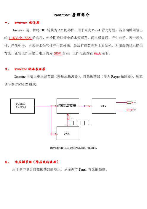
Inverter 原理简介一、Inverter 的作用Inverter 是一种将DC 转换为AC的器件,用于点亮Panel 背光灯管,其启动瞬间输出约1.1KV- 1.5KV的高压,使冷阴极灯管中的水银蒸发,两电极导通,产生电子,轰击氖气体,产生中子,再轰击水银气体产生紫外线,最后打在荧光粉上而发光,为图像的显示提供背光,正常工作后输出电压约为600V左右,工作电流约在6mA左右。
二、Inverter的基本组成Inverter主要由电压调节器(降压式斩波器)、自激振荡器(多为Royer振荡器)、脉宽调节器PWM IC组成。
INVERTER 基本架构(PWM IC:TL5001)三、电压调节器(降压式斩波器)用于调节供给自激振荡器的电压,从而调节Panel 背光的亮度。
Vo_D121Q3321Von/offR1++L114VinVo VdC1_Von/off输出电压为:V o=Vin*D=Vin*Ton/T(D :负占空比; Ton :Q3导通的时间; T :PWM 方波的周期时间)因T 一定,故输出电压V o 与导通时间成正比。
四、 PWM IC (TL5001为例)a.TL5001各脚简要说明PIN1:OUTPUT (输出占空比可调的方波) PIN5:SCP (短路保护)PIN2:VCC (IC 供电) PIN6:DTC (占空比限制)PIN3:COMP (比较器输出) PIN7:RT (振荡器外接电阻)PIN4:FB (反馈) PIN8:GNDTL5001内部结构图Q2TL5001的工作波形五、自激振荡器它是将DC转换为AC高压的主要部件。
Ib2Ib1Ic1Ic2Vc1Vc2C1、 C2是镇流电容,它使输出电流不会随灯管负载变化而变化很大。
R1、R2作为振荡器的启动电阻,由于晶体管Q1、Q2的特性不同,假设Q1先导通,Ic1慢慢上升(T1的第8脚的电动势为正,Q1维持导通状态,第7脚电动势为负,使Q2截止),上升至Q1完全饱和,此时Ic1不再变化,T1磁通变化量为零,使Q1截止, 产生反向电动势使Q2导通,Ic2慢慢上升,重复上述过程。
AC-coupled PV with Fronius PV InvertersThis document describes how to setup Energy-storage, Off-grid/Micro-grid and Backup systems with AC-coupled PV, using Fronius PV Inverters.Victron GX Devices, eg Cerbo GX also include built-in Fronius monitoring.For Fronius information on the same subject, see their MicroGrid flyer.A Victron & Fronius training webinar video is available to watch here.Video1.1 Frequency shiftingTo make sure that the Fronius PV inverter works well with Victron inverter/chargers, both must be configured with the right 'frequency shift settings':The Fronius PV Inverter must be set to Setup MG, short for Micro-Grid.For off-grid systems, load the Multi or Quattro with the PV Inverter support AssistantFor on-grid / energy-storage systems, load the Multi or Quattro with the ESS Assistant. Readinformation about ESS in the design-installation-manual.And the 1:1 limit rule must be adhered to.1.2 Fronius / Victron specificsThis is a very easy setup. The Fronius Setup Microgrid has been developed in close cooperation with Victron. During commissioning, set the PV Inverter to Setup MG50 (or Setup MG60 for 60 Hz systems). Everything is then pre-configured. The Setup MG settings match the default Victron Assistant settings.Compatible ROW inverters (for “European type AC grid”) are:Fronius Primo (1~, 3 kW up to 8.2 kW) → Software fro27140.upd or higher (see FAQ Q5!)Fronius Symo (3~, 3 kW up to 20 kW) → Software fro27140.upd or higher (see FAQ Q5!)Fronius Eco (3~, 25 kW or 27 kW) → Software fro27140.upd or higher (see FAQ Q5!)Fronius Agilo (3~, 75 kW up to 100 kW) → Software update19.tl or higherFronius IG Plus V (1~, 2~, 3~, 2.5 kW up to 12 kW) → from IGF 5.0.66 on with settings according to the Victron recommendationsFor new systems the Fronius Symo and Fronius Eco inverters are recommended for 3~ applications. The Fronius Primo inverters are recommended for 1~ applications. Please note that all these inverters are transformerless and therefore PV-Modules that require pole-grounding (on the Plus or Minus pole) cannot be connected.The use of Fronius Galvo inverters is not recommended anymore for new applications - the Fronius Primo is the best substitute and offers higher efficiency, wider DC voltage range and two MPP trackers.Compatible UL inverters (for “US type AC grid”) are:Fronius Primo UL (1~, 3.8 kW up to 15 kW) → Software fro27470.upd or higher (see FAQ Q5!) Fronius Symo 10-24 480V (3~, 10 kW up to 24 kW) → Software fro27140.upd or higher (see FAQ Q5!)Fronius Symo 10-15 208-240V (3~, 10 up to 15 kW) → Software fro27140.upd or higher (seeFAQ Q5!)For the UL inverters, some more Microgrid Setups are available (e.g. for connection with Neutral conductor or without). Also the UL inverters can be used in 60Hz as well as in 50Hz applications. More information can be found in the user manuals.When setting up a system, always update both the Fronius and the Victron devices to their latestfirmware versions. For the latest Fronius firmware and information how to update use this link: Fronius firmware update1.3 Setting up the Fronius with Setup MG50/MG60When not pre-ordered with a MicroGrid setup, follow these steps:1.Make sure that the Fronius PV inverter is updated to at least the firmware version mentioned above. See Inverter list above.2.After making the inverter operational according to the manual, select the language and after this the country specific setup.3.Here choose MG50 or MG60 depending on the system frequency.4.Ready to start up.1.4 Setting up the Victron Multi or Quattro1.After connecting the MultiPlus or Quattro with the battery, you can now connect a computerthrough the VE.Bus (in combination with the Victron interface MK2USB) to configure the system with the latest version of the software VE.Configure.2.Go to the tab Assistants:3.Add one of the Assistants that regulate output frequency:1.ESS Assistant2.PV Inverter supportNote that it is not necessary to change the default settings in the Assistant.4.5.Complete the rest of the Assistant and write the new settings to the MultiPlus or Quattro. Table with general suggested settings for 50Hz and 60Hz frequencyState50Hz60Hz.Start50.260.2HzMinimum52.762.7HzDisconnect53.063.0HzNote that although the MG50 for instance has a higher start frequency of 51Hz, there is no real drawback using the proposed value of 50.2Hz. The system will just increase the frequency until the PV inverter regulation kicks in. The value of 50.2Hz will work with a broader range of PV inverters/grid codes.More information on adding Assistants is here.2. GX Devices & Fronius PV InvertersBy connecting a Fronius PV Inverter and GX device (eg Cerbo GX) together you will be able to: 1.See Fronius information on the GX Device.2.Monitor the Fronius on the VRM Portal.3.Allow the Victron system to control the Fronius output power, Zero feed-in. See the ESS manual, chapter 2.1.3 Fronius Zero feed-in for details.This document describes how to setup the monitoring functions.2.1 RequirementsModel Required accessoryFronius Symo Light Purchase and install the datamanager 2.0Fronius Symo No accessory needed, datamanager card installed from factoryFronius Galvo No accessory needed, datamanager card installed from factoryFronius Primo No accessory needed, datamanager card installed from factoryFronius Eco No accessory needed, datamanager card installed from factoryFronius IG Plus (*)Purchase and install the datamanager 2.0Fronius Agilo Purchase and install the datamanager boxFronius GEN24See here for limitations and GEN24 special procedure(*) The Fronius Zero feed-in feature - which is part of an Energy Storage System ESS - will work on all the above models except the IG Plus.All recent Fronius inverters - for example the Fronius Primo - will arrive fitted with a datamanager 2.0, as standard.Both the Fronius and the GX Device need to be connected on the same LAN - either via Wi-Fi or Ethernet.Note that the Datalogger Web is not supported. Contact your Fronius dealer to find out about the upgrading options.2.2. Configuring2.2.1 Setup Local Area Network (LAN) ConfigurationIn order to establish a data communication between the Fronius and the GX Device, you will have to setup a valid LAN IP address on the Fronius, using one of the following methods. If you are in doubt, which method is the best for your network, please ask your system administrator or IT support.2.2.1.1 DHCP addressing methodIf you have a DHCP server running on the LAN the Fronius and GX Device are connected to, you don't need to manually configure your LAN IP addresses as the DHCP server does this for you. Make sure, that the “IP Switch” is in “B” (default) position on the datamanager, to allow the Fronius to obtain it's IP address. It can be reviewed in the Address Lease Table of the DHCP server.2.2.1.2 Link-local addressing methodWhen no DHCP server is present on the LAN and you only have one Fronius unit to connect, Link-local addressing can be used to establish data communication between the GX Device and the Fronius. This could be the case, if you use a WiFi Network for the GX Device to gain access to the Internet and have a Fronius connected to the wired LAN Interface of that GX Device.Note, that no direct access to the internet will be possible for the Fronius in that configuration and therefore only communication to the GX Device is possible.This method can only be used to configure a single Fronius unit within a LAN. Multiple Fronius devices in the same LAN must be configured with DHCP, or manual addressing method.1.Make sure the “IP Switch” on the Fronius Datamanager is on position “A”2.Connect both, the Fronius and the GX Device, on the same LAN network, either directly with a LAN cable or using a network switch.3.The Fronius is now accessible and having a “Link-local” capable IP address configured:169.254.0.1802.2.1.3 manual addressing methodYou will have to configure the IP address of the Fronius to be in the same subnet as the IP address of the GX Device. To do this, first have a look at the IP configuration your GX Device is using on thatnetwork.The IP configuration can be reviewed in Settings –> Ethernet. The important settings are the IP address and Subnet Mask.If the LAN IP address and Subnet Mask of the GX Device is not configured yet, you will have to set it first.As an example, the IP address on the GX Device could be: 192.168.10.1 and the Subnet Mask: 255.255.255.0.Configuring the Fronius to the same subnet means setting a manual IP address to: 192.168.10.2 and the same Subnet Mask of 255.255.255.0 on the Fronius.Every device on your LAN has to have a unique (different) IP address and so the last segment (.1/.2) in this example has to differ on every device on the same LAN. The highest value, that can be set for this segment is 254.The subnet is described by the first 3 segments in this case and so they have to be the same.Configuring multiple devices with exactly the same IP addresses will lead to network errors. Usedifferent IP subnets for the WiFi and wired LAN interface. The IP address ranges used on each interface should differ in the third segment.As an example: 192.168.10.1-254 for LAN IP's and 192.168.11.1-254 for WiFi IP's.Configure the Fronius Datamanager to use an IP address on the same subnet, as described above. You may need to refer to the Fronius operating manual for how this is done for your Fronius Inverter model,If you would like to connect the Fronius to be able to use the internet connection of your Local network, you have to set Gateway and DNS IP addresses on the Fronius as well. They should be exactly the same as in the Settings –> Ethernet of the GX Device.2.2.1.4 special procedure for GEN24 modelIn Fronius GEN24 devices with software version 1.14 or higher, the Solar API interface is not activated by default and must be activated if required (e.g. integration of a GX device).The setting for this can be found on the user interface of the Fronius inverter under “Communication”- “Solar API”.For GEN24, there is no physical toggle switch required (as there is with other models).Victron and Fronius have made no tests, nor make any claims about the performance of this integration. If light flickering issues occur, please contact your Fronius dealer.2.2.2 Adding Fronius to the GX Device1. In the GX Device, navigate to Settings and then the PV Inverters section. You will see this menu:2. Select Scan in the GX Device menu, and after completion go into the Inverters submenu to see the results. If scanning does not find the inverter, manually add the IP address of the Fronius Datamanager from its card, or box.3. The GX Device will automatically scan for PV-inverters on the local network if no PV-inverters were found previously or if a previously-found PV-inverter cannot be contacted. This will happen if the IP address of the PV-inverter changes. To prevent automatic scanning, disable Automatic scanning.We recommend that automatic scanning is enabled (the default) in residential and smallcommercial applications.In larger installations, or where the scanning interferes with other equipment on the network, automatic scanning should be disabled.Note that if DHCP is used to allocate dynamic addresses in your computer network, theconnection to your PV-inverter may be permanently lost if automatic scanning is disabled and the IP-address of the PV-inverter changes.4. Once located, you will see the Inverters listed in the menu. The name used will be the serial number of the inverter - which you will also find on the inverter itself:5. Configure the position relative to the Multi or Quattro (is it: AC Input / AC Output); and the showsetting for each inverter in the list:Position: Select the position relative to the Multi or Quattro [AC Input 1 / AC Input 2 / AC Output] Show: Select whether to how this inverter in the system or not. Use this feature when there are multiple, separate, energy systems on the same LAN.6. Configure the phase for each inverter in the list:Phase: Select the phase on which the PV Inverter installed. This setting is automatically set to Multi-phase for split- and three-phase PV Inverters.In some cases a single-phase PV inverter may deliver power at 240V or 208V across twodownstream phases, such as in a residential split-phase configuration in North America. In this case the setting will not be set to Multi-phase automatically and you need to select Split-phase (L1+L2). This instructs the GX Device to divide the measured incoming power evenly across the two phases for display and accounting purposes.7. Done!2.2.3 Device scan detailsAs mentioned above the GX Device should find all Fronius inverters automatically. It will scan all IP-addresses in the local network (that is, all IP-addresses within the netmask assigned to the GX Device) to check whether or not they are Fronius datamanager cards. This scan will be performed during GX Device startup; whenever the GX Device loses connection to a data card; and a scan can also be initiated manually by selecting 'Press to scan'.Usually a scan is completed within a minute - though if you have a large subnet it may take much more time. If you don't want to wait for completion, enter an IP-address manually.All data cards found will be entered in the 'Detected data cards' list. The GX Device will regularly (once every minute) scan the IP-addresses in this list in order to find new data cards, or reconnect to data cards whenever the connection was lost.If you don't want an automatic scan to be performed, disable the Automatic scanning setting on the PV-inverters menu.2.3 Monitoring GX DeviceWhen the Fronius is detected and configured on the GX Device all PV inverters will be visible in the devicelist.To see the device details, navigate to the menu. Here you can see the current state, current power generated, total power generated.For more details on each device navigate to the Device menu. Here you will find: IP address, Product name, product ID, and Serial number, etc.Inverter statusThe following status values are supported:State MeaningStandby The PV-inverter is not generating power.Startup The PV-inverter is starting up, but not generating power yet. Running (MPPT)The PV-inverter is running at maximum power.Running (Throttled)The PV-inverter is running, but power is being throttled.Error One or more errors are present.Note that not all errors will cause the PV-inverter to shut down.2.4 Monitoring on the VRM PortalTo see the yield on the VRM site (in the Advanced tab), don't forget to enable the PV Inverter yield widget(s) in Settings → Advanced tab setup.2.5 Zero Feed-inIt is possible to make a Zero feed-in system with Victron & Fronius. The Venus device will the control the Fronius output power. See the ESS manual, chapter 4.3.13 - AC-Coupled PV - Zero and Limited Feed-in with Fronius AC PV for details.3. Frequently Asked QuestionsQ1 Why doesn't the frequency settings in the Multi and the Fronius need to be the same?The first two frequencies do not need to be the same since the Multi actively regulates.Q2 I have an Fronius IG inverter (not Plus), can that work?No, the IG inverters cannot be made to work in a MicroGrid system. The appropriate substitute for an IG 30 is the GALVO 2.5-1 or an IG Plus 25V-1 (depending on the desired DC voltage range).Q3 The system is locked to 53 Hz and does not resumeSee here.Q4 Can I use the Fronius Smart Meter?That depends on the type of system and software configuration.A Fronius Smart Meter can be used in these two situations:1.when used only for reporting to Solarweb2.when used for limiting export, in a system where the Victron system is not configured as an ESS system.The Fronius Smart-Meter can not be used for the Fronius built-in export limiting feature when part of a Victron ESS system. Instead, use the Victron ESS Fronius Zero-feed in feature, see chapter 4.3.11, Fronius Zero Feed-in, in the ESS manual.Q5 How can I get the Fronius firmware that improves flickering?Fronius has a special firmware available, on request, that fixes light flickering issues that occur on certain installations under certain circumstances.For Fronius PV inverters produced after 2018-week 16, contain the flicker-fix already straight from production.To update earlier and/or already installed PV Inverters, contact Fronius Tech Support for the file. The required file is fro29130.upd. Which works for all snap-inverter models (Primo, Symo and Eco). There is no, and will be no, fix available for Fronius Galvos.Q6 What do I do if my Fronius PV-inverter is detected as Unknown PV-inverter, or Multiphase, or cannot be configured as 3-phase?Later Fronius PV-inverters support both the Fronius SolarAPI- as well as the industry standard SunSpec protocol. When SunSpec is not available the GX device cannot properly detect the properties of the PV-inverter unless it is one of a fixed list of known older models. Newer PV-inverters will then show up as Unknown, and you will not be able to configure them as 3-phase.The solution is to configure SunSpec support on the PV-inverter.Log into the Fronius web interface.Go to the Modbus tabSet Data export via Modbus to tcp.set Sunspec Model Type to int + SFDISQUSView the discussion thread.。
PV系列变频器用户手册资料版本V1.4归档日期2018-09-14BOM 编码 31012007本用户手册著作权归属于利莱森玛电机科技(福州)有限公司深圳光明分公司。
用户手册内容如有改动,恕不另行通知。
地址:深圳市南山区科技工业园科技路一号桑达科技大厦三楼邮编:518057公司网址:客户服务热线:400-887-9230目录序言 (1)1.1 开箱检查注意事项 (1)1.2 变频器型号说明 (1)第一章安全信息 (2)1.1 安全定义 (2)1.2 安装注意事项 (2)1.3 使用注意事项 (2)1.3.1 关于电动机及机械负载 (2)1.3.2 关于变频器 (3)1.4 报废注意事项 (3)第二章产品介绍 (4)2.1 通用技术规格 (4)2.2 产品系列介绍 (5)2.2.1 额定值 (5)2.2.2 变频器各部位名称说明 (5)2.2.3 外形尺寸及毛重 (6)2.3 选配件 (8)2.3.1 LCD操作面板 (8)2.3.2 制动组件 (8)2.3.3 通信组件 (9)第三章安装及配线 (11)3.1 变频器的安装环境 (11)3.2 变频器部件的拆卸和安装 (11)3.2.1 操作面板的拆卸和安装 (11)3.2.2 盖板的拆卸和安装 (12)3.3 变频器的配线 (12)3.3.1 主回路端子配线及配置 (13)3.3.2 控制回路配置及配线 (18)3.4 符合EMC要求的安装指导 (25)3.4.1 噪声抑制 (25)3.4.2 现场配线要求 (26)3.4.3 接地 (27)3.4.4 继电器、接触器及电磁制动器的安装要求 (27)3.4.5 漏电流及其对策 (27)3.4.6 变频器的正确EMC安装 (28)3.4.7 电源滤波器使用指南 (29)3.4.8 变频器辐射发射 (29)第四章变频器运行和操作说明 (30)4.1 解释说明 (30)4.1.1 变频器运行命令通道 (30)4.1.2 变频器频率给定通道 (30)4.1.3 变频器工作状态 (30)4.1.4 变频器运行方式 (30)4.2 详细操作指南 (31)4.2.1 操作面板的使用 (31)4.2.2 按键功能说明 (32)4.2.3 LED数码管及指示灯说明 (32)4.2.4 操作面板的显示状态 (32)4.2.5 操作面板的操作方法 (33)4.3 首次上电 (35)4.3.1 上电前的检查 (35)4.3.2 初次上电操作 (35)第五章详细功能介绍 (36)5.1 基本运行参数(F0组) (36)5.2 频率给定参数(F1组) (38)5.3 起动制动参数(F2组) (39)5.4 辅助运行参数(F3组) (41)5.5 过程闭环控制参数(F5组) (43)5.6 端子功能参数(F7组) (46)5.7 显示控制参数(F8组) (52)5.8 增强功能参数(F9组) (53)5.9 通讯参数(FF组) (58)5.10 电机参数(FH组) (59)5.11 保护相关参数(FL组) (60)5.12 变频器自身参数(Fn组) (62)5.13 参数保护(FP组) (62)第六章故障对策及异常处理 (64)第七章保养和维护 (67)7.1 日常保养和维护 (67)7.2 定期维护 (67)7.3 变频器易损件更换 (68)7.4 变频器的存贮 (68)7.5 变频器的保修 (68)附录一功能参数简表 (69)附录二推荐的配件参数 (86)1. 交直流电抗器 (86)附录三通讯协议 (90)1. 组网方式 (90)2. 接口方式 (90)3. 通信方式 (90)4. 协议格式 (91)5. 格式解释 (91)序言 1序言感谢您购买尼得科Control Techniques生产的PV系列变频器(或简称变频器)。
光伏逆变器的源程序光伏逆变器(PV inverter)的源程序通常涉及复杂的控制算法、电力电子技术和通信协议。
由于这是一个非常专业的领域,并且每个制造商的逆变器设计可能有所不同,因此提供完整的源程序是不现实的。
但我可以给你一个简化的概念框架或示例代码,帮助你理解逆变器控制软件的基本结构。
以下是一个非常简化的伪代码示例,描述了光伏逆变器可能会执行的一些基本操作:c// 伪代码,非真实逆变器控制程序// 初始化变量和系统配置void initialize() {// 设置MPPT(最大功率点跟踪)算法参数// 配置PID(比例-积分-微分)控制器参数// 初始化通信接口(如Modbus, CAN等)// ...}// MPPT算法,用于确定光伏板的最佳工作电压和电流void mpptAlgorithm() {// 读取光伏板当前的电压和电流float currentVoltage = readPVVoltage();float currentCurrent = readPVCurrent();// 使用某种MPPT算法(如扰动和观察法)来计算新的电压或电流参考值float newVoltageRef = calculateMPPTVoltage(currentVoltage, currentCurrent);// 设置逆变器以尝试达到新的工作点setInverterVoltageReference(newVoltageRef);}// PID控制器,用于调节逆变器输出以匹配电网要求void pidController() {// 读取电网电压和频率float gridVoltage = readGridVoltage();float gridFrequency = readGridFrequency();// 计算与电网同步所需的相位角和电压幅值调整量float phaseAngleAdjustment = calculatePhaseAngle(gridFrequency);float voltageAmplitudeAdjustment = calculateVoltageAmplitude(gridVoltage);// 使用PID控制器调整逆变器输出电流的频率、相位和幅值以匹配电网adjustInverterOutput(phaseAngleAdjustment, voltageAmplitudeAdjustment);}// 主循环,不断执行MPPT和PID控制算法,以及其他任务void mainLoop() {while (true) {mpptAlgorithm(); // 运行MPPT算法以优化光伏板输出pidController(); // 运行PID控制器以匹配电网要求// 执行其他任务,如通信、故障诊断、系统监控等...communicateWithExternalDevices(); // 与外部设备通信(如智能家居系统)diagnoseFaults(); // 检测并处理任何故障情况(如过温、过流等)monitorSystemStatus(); // 监控系统状态并记录数据以供分析或故障排除使用delay(controlLoopTime); // 等待一段时间再次执行循环(控制环时间间隔)}}int main() {initialize(); // 初始化系统配置和变量mainLoop(); // 进入主控制循环,不断运行控制算法和其他任务...return 0; // 通常这里不会返回,因为主循环是无限循环的...但为了形式完整性还是加上这一行。
太陽光變頻器(PV inverter)
太陽光變頻器(P h o t o v o l t a i c I n v e r t e r,簡稱P V i n v e r t e r),或稱太陽能光電轉換器,可將太陽光電系統所產生的直流電轉換成交流電,並且可直接將太陽能光電池所產生的電能饋入市電,提供使用者的自用電源,或提供給公眾電源。
如果用電設施是使用直流電,則不需要裝置I n v e r t e r。
太陽光電系統之主要零配件包括:成本佔整個P V系統約50%以上之太陽光電模組、及成本佔約20%之電力調節器(內含濾波器、穩壓器、變頻器、電驛等零元件),其中P V i n v e r t e r 約佔系統成本10~15%。
太陽光電模組之主要構成元件為太陽能電池(S o l a r C e l l),而電力調節器之關鍵零組件為變頻器(I n v e r t e r s)。
◎太陽光變頻器分為三種型式:
1.離線型(o f f-g r i d):或稱獨立(s t a n d-a l o n e)型,此種變頻器由電池供電,產生方波或弦波型式的交流輸出,提供獨立系統的用電,具有蓄電池之獨立型產品,但無法與市電併聯。
2.併網型(g r i d-c o n n e c t e d o r l i n e-t i e d):變頻器產生與市電同步的弦波電流輸出,可與市電併聯,將太陽光電池的輸出電能直接轉換為市電,但無法獨立供電。
在電力供應穩定的地區,市電併聯型系統不需使用電池進行電能儲備。
3.混和型(h y b r i d):可與市電併聯也可與電池連接,對特定連接的負載可提供獨立供電,具有不斷電系統(U P S)的功能,當市電斷電時,有如併網型U P S,藉由電池提供電源。
資料來源:S o l a r P V
三種型式太陽光電變頻器,以併網型P V系統為先進國家P V市場的主流,而台灣P V I n v e r t e r 的發展,多數偏向於併聯型P V I n v e r t e r。
當P V與市電的每度電成本接近時,可帶動P V的普及,最快在2013年,美國加州的太陽能每度電成本可降至40美分,接近與市電的35美分。
P V I n v e r t e r供應商包括龍頭廠德國S M A、K A C O、奧地利F r o n i u s、加拿大Xa n t r e x等代表廠,S M A為全球最大太陽能轉換器供應商,市佔率約為40%~45%。
由於P V I n v e r t e r與U P S同質性高,切入P V I n v e r t e r的廠商,大多在電源供應與電源管理設備有經驗的廠商,國內投入廠商包括電源供應器廠的台達電與全漢、U P S的科風與飛瑞、及漢唐轉投資的盈正。
由於P V i n v e r t e r涉及用電安全,規定較為嚴格,且併網型使用之P V i n v e r t e r難度較高,認證通常須時6個月,故新進者短期內將無法快速進入。
2010年P V i n v e r t e r產值將達32億美元,Yo Y+50%。
根據S o l a r b u z z全球太陽能光電設備的發電量,在2007年達到歷史新高的2,826 M W,較2006年大幅成長了62%,至2009年全球太陽能光電裝機容量達 6.43G W,歐洲國家共安裝 4.75G W,佔全球需求量的比例約74%,其中德國、義大利及捷克三個國家的安裝量就
達到 4.07G W。