MAX6380_R34-T中文资料
- 格式:pdf
- 大小:157.35 KB
- 文档页数:7


General DescriptionThe MAX13080E–MAX13089E +5.0V, ±15kV ESD-protect-ed, RS-485/RS-422 transceivers feature one driver and one receiver. These devices include fail-safe circuitry,guaranteeing a logic-high receiver output when receiver inputs are open or shorted. The receiver outputs a logic-high if all transmitters on a terminated bus are disabled (high impedance). The MAX13080E–MAX13089E include a hot-swap capability to eliminate false transitions on the bus during power-up or hot insertion.The MAX13080E/MAX13081E/MAX13082E feature reduced slew-rate drivers that minimize EMI and reduce reflections caused by improperly terminated cables, allowing error-free data transmission up to 250kbps. The MAX13083E/MAX13084E/MAX13085E also feature slew-rate-limited drivers but allow transmit speeds up to 500kbps. The MAX13086E/MAX13087E/MAX13088E driver slew rates are not limited, making transmit speeds up to 16Mbps possible. The MAX13089E slew rate is pin selectable for 250kbps,500kbps, and 16Mbps.The MAX13082E/MAX13085E/MAX13088E are intended for half-duplex communications, and the MAX13080E/MAX13081E/MAX13083E/MAX13084E/MAX13086E/MAX13087E are intended for full-duplex communica-tions. The MAX13089E is selectable for half-duplex or full-duplex operation. It also features independently programmable receiver and transmitter output phase through separate pins.The MAX13080E–MAX13089E transceivers draw 1.2mA of supply current when unloaded or when fully loaded with the drivers disabled. All devices have a 1/8-unit load receiver input impedance, allowing up to 256transceivers on the bus.The MAX13080E/MAX13083E/MAX13086E/MAX13089E are available in 14-pin PDIP and 14-pin SO packages.The MAX13081E/MAX13082E/MAX13084E/MAX13085E/MAX13087E/MAX13088E are available in 8-pin PDIP and 8-pin SO packages. The devices operate over the com-mercial, extended, and automotive temperature ranges.ApplicationsUtility Meters Lighting Systems Industrial Control Telecom Security Systems Instrumentation ProfibusFeatures♦+5.0V Operation♦Extended ESD Protection for RS-485/RS-422 I/O Pins±15kV Human Body Model ♦True Fail-Safe Receiver While Maintaining EIA/TIA-485 Compatibility ♦Hot-Swap Input Structures on DE and RE ♦Enhanced Slew-Rate Limiting Facilitates Error-Free Data Transmission(MAX13080E–MAX13085E/MAX13089E)♦Low-Current Shutdown Mode (Except MAX13081E/MAX13084E/MAX13087E)♦Pin-Selectable Full-/Half-Duplex Operation (MAX13089E)♦Phase Controls to Correct for Twisted-Pair Reversal (MAX13089E)♦Allow Up to 256 Transceivers on the Bus ♦Available in Industry-Standard 8-Pin SO PackageMAX13080E–MAX13089E+5.0V , ±15kV ESD-Protected, Fail-Safe, Hot-Swap, RS-485/RS-422 Transceivers________________________________________________________________Maxim Integrated Products 1Ordering Information19-3590; Rev 1; 4/05For pricing, delivery, and ordering information,please contact Maxim/Dallas Direct!at 1-888-629-4642, or visit Maxim’s website at .Selector Guide, Pin Configurations, and Typical Operating Circuits appear at end of data sheet.Ordering Information continued at end of data sheet.M A X 13080E –M A X 13089E+5.0V , ±15kV ESD-Protected, Fail-Safe, Hot-Swap, RS-485/RS-422 Transceivers 2_______________________________________________________________________________________ABSOLUTE MAXIMUM RATINGSDC ELECTRICAL CHARACTERISTICS(V CC = +5.0V ±10%, T A = T MIN to T MAX , unless otherwise noted. Typical values are at V CC = +5.0V and T A = +25°C.) (Note 1)Stresses beyond those listed under “Absolute Maximum Ratings” may cause permanent damage to the device. These are stress ratings only, and functional operation of the device at these or any other conditions beyond those indicated in the operational sections of the specifications is not implied. Exposure to absolute maximum rating conditions for extended periods may affect device reliability.(All Voltages Referenced to GND)Supply Voltage (V CC ).............................................................+6V Control Input Voltage (RE , DE, SLR,H/F , TXP, RXP)......................................................-0.3V to +6V Driver Input Voltage (DI)...........................................-0.3V to +6V Driver Output Voltage (Z, Y, A, B).............................-8V to +13V Receiver Input Voltage (A, B)....................................-8V to +13V Receiver Input VoltageFull Duplex (A, B)..................................................-8V to +13V Receiver Output Voltage (RO)....................-0.3V to (V CC + 0.3V)Driver Output Current.....................................................±250mAContinuous Power Dissipation (T A = +70°C)8-Pin SO (derate 5.88mW/°C above +70°C).................471mW 8-Pin Plastic DIP (derate 9.09mW/°C above +70°C).....727mW 14-Pin SO (derate 8.33mW/°C above +70°C)...............667mW 14-Pin Plastic DIP (derate 10.0mW/°C above +70°C)...800mW Operating Temperature RangesMAX1308_EC_ _.................................................0°C to +75°C MAX1308_EE_ _..............................................-40°C to +85°C MAX1308_EA_ _............................................-40°C to +125°C Junction Temperature......................................................+150°C Storage Temperature Range.............................-65°C to +150°C Lead Temperature (soldering, 10s).................................+300°CMAX13080E–MAX13089E+5.0V , ±15kV ESD-Protected, Fail-Safe, Hot-Swap, RS-485/RS-422 Transceivers_______________________________________________________________________________________3DC ELECTRICAL CHARACTERISTICS (continued)(V CC = +5.0V ±10%, T A = T MIN to T MAX , unless otherwise noted. Typical values are at V CC = +5.0V and T A = +25°C.) (Note 1)M A X 13080E –M A X 13089E+5.0V , ±15kV ESD-Protected, Fail-Safe, Hot-Swap, RS-485/RS-422 Transceivers 4_______________________________________________________________________________________DRIVER SWITCHING CHARACTERISTICSMAX13080E/MAX13081E/MAX13082E/MAX13089E WITH SRL = UNCONNECTED (250kbps)(V CC = +5.0V ±10%, T A = T MIN to T MAX , unless otherwise noted. Typical values are at V CC = +5.0V and T A = +25°C.)RECEIVER SWITCHING CHARACTERISTICSMAX13080E/MAX13081E/MAX13082E/MAX13089E WITH SRL = UNCONNECTED (250kbps)(V CC = +5.0V ±10%, T A = T MIN to T MAX , unless otherwise noted. Typical values are at V CC = +5.0V and T A = +25°C.)MAX13080E–MAX13089E+5.0V , ±15kV ESD-Protected, Fail-Safe, Hot-Swap, RS-485/RS-422 Transceivers_______________________________________________________________________________________5DRIVER SWITCHING CHARACTERISTICSMAX13083E/MAX13084E/MAX13085E/MAX13089E WITH SRL = V CC (500kbps)(V CC = +5.0V ±10%, T A = T MIN to T MAX , unless otherwise noted. Typical values are at V CC = +5.0V and T A = +25°C.)RECEIVER SWITCHING CHARACTERISTICSMAX13083E/MAX13084E/MAX13085E/MAX13089E WITH SRL = V CC (500kbps)(V CC = +5.0V ±10%, T A = T MIN to T MAX , unless otherwise noted. Typical values are at V CC = +5.0V and T A = +25°C.)M A X 13080E –M A X 13089E+5.0V , ±15kV ESD-Protected, Fail-Safe, Hot-Swap, RS-485/RS-422 Transceivers 6_______________________________________________________________________________________DRIVER SWITCHING CHARACTERISTICSMAX13086E/MAX13087E/MAX13088E/MAX13089E WITH SRL = GND (16Mbps)(V CC = +5.0V ±10%, T A = T MIN to T MAX , unless otherwise noted. Typical values are at V CC = +5.0V and T A = +25°C.)RECEIVER SWITCHING CHARACTERISTICSMAX13086E/MAX13087E/MAX13088E/MAX13089E WITH SRL = GND (16Mbps)(V CC = +5.0V ±10%, T A = T MIN to T MAX , unless otherwise noted. Typical values are at V CC = +5.0V and T A = +25°C.)Note 2:∆V OD and ∆V OC are the changes in V OD and V OC , respectively, when the DI input changes state.Note 3:The short-circuit output current applies to peak current just prior to foldback current limiting. The short-circuit foldback outputcurrent applies during current limiting to allow a recovery from bus contention.MAX13080E–MAX13089E+5.0V , ±15kV ESD-Protected, Fail-Safe, Hot-Swap, RS-485/RS-422 Transceivers_______________________________________________________________________________________70.800.901.501.101.001.201.301.401.60-40-10520-253550958011065125SUPPLY CURRENT vs. TEMPERATURETEMPERATURE (°C)S U P P L Y C U R R E N T (m A )0201040305060021345OUTPUT CURRENTvs. RECEIVER OUTPUT-HIGH VOLTAGEM A X 13080E -89E t o c 02OUTPUT HIGH VOLTAGE (V)O U T P U T C U R R E N T (m A )20104030605070021345OUTPUT CURRENTvs. RECEIVER OUTPUT-LOW VOLTAGEM A X 13080E -89E t o c 03OUTPUT LOW VOLTAGE (V)O U T P U T C U R R E N T (m A )4.04.44.24.84.65.25.05.4RECEIVER OUTPUT-HIGH VOLTAGEvs. TEMPERATURETEMPERATURE (°C)O U T P U T H I G H V O L T A G E (V )-40-10520-2535509580110651250.10.70.30.20.40.50.60.8RECEIVER OUTPUT-LOW VOLTAGEvs. TEMPERATURETEMPERATURE (°C)O U T P U T L O W V O L T A G E (V )-40-10520-25355095801106512502040608010012014016012345DRIVER DIFFERENTIAL OUTPUT CURRENT vs. DIFFERENTIAL OUTPUT VOLTAGEDIFFERENTIAL OUTPUT VOLTAGE (V)D I F FE R E N T I A L O U T P U T C U R R E N T (m A )2.02.82.43.63.24.44.04.8DRIVER DIFFERENTIAL OUTPUT VOLTAGE vs. TEMPERATURED I F FE R E N T I A L O U T P U T V O L T A G E (V )-40-10520-253550958011065125TEMPERATURE (°C)40201008060120140180160200-7-5-4-6-3-2-1012354OUTPUT CURRENT vs. TRANSMITTEROUTPUT-HIGH VOLTAGEOUTPUT HIGH VOLTAGE (V)O U T P U T C U R R E N T (m A )60402080100120140160180200042681012OUTPUT CURRENT vs. TRANSMITTEROUTPUT-LOW VOLTAGEOUTPUT-LOW VOLTAGE (V)O U T P U T C U R R E N T (m A )Typical Operating Characteristics(V CC = +5.0V, T A = +25°C, unless otherwise noted.)M A X 13080E –M A X 13089E+5.0V , ±15kV ESD-Protected, Fail-Safe, Hot-Swap, RS-485/RS-422 Transceivers 8_______________________________________________________________________________________21543679810SHUTDOWN CURRENT vs. TEMPERATUREM A X 13080E -89E t o c 10S H U T D O W N C U R R E N T (µA )-40-10520-253550958011065125TEMPERATURE (°C)600800700100090011001200DRIVER PROPAGATION DELAY vs. TEMPERATURE (250kbps)D R I VE R P R O P A G A T I O N D E L A Y (n s )-40-10520-253550958011065125TEMPERATURE (°C)300400350500450550600DRIVER PROPAGATION DELAY vs. TEMPERATURE (500kbps)D R I VE R P R O P A G A T I O N D E L A Y (n s )-40-10520-253550958011065125TEMPERATURE (°C)1070302040506080DRIVER PROPAGATION DELAY vs. TEMPERATURE (16Mbps)D R I VE R P R O P A G A T I O N D E L A Y (n s )-40-10520-253550958011065125TEMPERATURE (°C)40201008060120140160180RECEIVER PROPAGATION DELAYvs. TEMPERATURE (250kpbs AND 500kbps)R E C E I V E R P R O P A G A T I O N D E L A Y (n s )-40-10520-253550958011065125TEMPERATURE (°C)40201008060120140160180RECEIVER PROPAGATION DELAYvs. TEMPERATURE (16Mbps)R EC E I V E R P R O P A G AT I O N D E L A Y (n s )-40-10520-253550958011065125TEMPERATURE (°C)2µs/div DRIVER PROPAGATION DELAY (250kbps)DI 2V/divV Y - V Z 5V/divR L = 100Ω200ns/divRECEIVER PROPAGATION DELAY(250kbps AND 500kbps)V A - V B 5V/divRO 2V/divTypical Operating Characteristics (continued)(V CC = +5.0V, T A = +25°C, unless otherwise noted.)MAX13080E–MAX13089E+5.0V , ±15kV ESD-Protected, Fail-Safe, Hot-Swap, RS-485/RS-422 Transceivers_______________________________________________________________________________________9Test Circuits and Waveforms400ns/divDRIVER PROPAGATION DELAY (500kbps)DI 2V/divR L = 100ΩV Y - V Z 5V/div10ns/div DRIVER PROPAGATION DELAY (16Mbps)DI 2V/divR L = 100ΩV Y 2V/divV Z 2V/div40ns/divRECEIVER PROPAGATION DELAY (16Mbps)V B 2V/divR L = 100ΩRO 2V/divV A 2V/divTypical Operating Characteristics (continued)(V CC = +5.0V, T A = +25°C, unless otherwise noted.)Figure 2. Driver Timing Test CircuitM A X 13080E –M A X 13089E+5.0V , ±15kV ESD-Protected, Fail-Safe, Hot-Swap, RS-485/RS-422 Transceivers 10______________________________________________________________________________________Test Circuits and Waveforms (continued)Figure 4. Driver Enable and Disable Times (t DHZ , t DZH , t DZH(SHDN))DZL DLZ DLZ(SHDN)MAX13080E–MAX13089E+5.0V , ±15kV ESD-Protected, Fail-Safe, Hot-Swap, RS-485/RS-422 TransceiversTest Circuits and Waveforms (continued)Figure 6. Receiver Propagation Delay Test CircuitM A X 13080E –M A X 13089E+5.0V , ±15kV ESD-Protected, Fail-Safe, Hot-Swap, RS-485/RS-422 TransceiversMAX13080E–MAX13089E+5.0V , ±15kV ESD-Protected, Fail-Safe, Hot-Swap, RS-485/RS-422 TransceiversMAX13080E/MAX13083E/MAX13086EMAX13081E/MAX13084E/MAX13086E/MAX13087EFunction TablesM A X 13080E –M A X 13089E+5.0V , ±15kV ESD-Protected, Fail-Safe, Hot-Swap, RS-485/RS-422 Transceivers MAX13082E/MAX13085E/MAX13088EFunction Tables (continued)MAX13089EDetailed Description The MAX13080E–MAX13089E high-speed transceivers for RS-485/RS-422 communication contain one driver and one receiver. These devices feature fail-safe circuit-ry, which guarantees a logic-high receiver output when the receiver inputs are open or shorted, or when they are connected to a terminated transmission line with all dri-vers disabled (see the Fail-Safe section). The MAX13080E/MAX13082E/MAX13083E/MAX13085E/ MAX13086E/MAX13088E/MAX13089E also feature a hot-swap capability allowing line insertion without erroneous data transfer (see the Hot Swap Capability section). The MAX13080E/MAX13081E/MAX13082E feature reduced slew-rate drivers that minimize EMI and reduce reflec-tions caused by improperly terminated cables, allowing error-free data transmission up to 250kbps. The MAX13083E/MAX13084E/MAX13085E also offer slew-rate limits allowing transmit speeds up to 500kbps. The MAX13086E/MAX13087E/MAX13088Es’ driver slew rates are not limited, making transmit speeds up to 16Mbps possible. The MAX13089E’s slew rate is selectable between 250kbps, 500kbps, and 16Mbps by driving a selector pin with a three-state driver.The MAX13082E/MAX13085E/MAX13088E are half-duplex transceivers, while the MAX13080E/MAX13081E/ MAX13083E/MAX13084E/MAX13086E/MAX13087E are full-duplex transceivers. The MAX13089E is selectable between half- and full-duplex communication by driving a selector pin (H/F) high or low, respectively.All devices operate from a single +5.0V supply. Drivers are output short-circuit current limited. Thermal-shutdown circuitry protects drivers against excessive power dissi-pation. When activated, the thermal-shutdown circuitry places the driver outputs into a high-impedance state.Receiver Input Filtering The receivers of the MAX13080E–MAX13085E, and the MAX13089E when operating in 250kbps or 500kbps mode, incorporate input filtering in addition to input hysteresis. This filtering enhances noise immunity with differential signals that have very slow rise and fall times. Receiver propagation delay increases by 25% due to this filtering.Fail-Safe The MAX13080E family guarantees a logic-high receiver output when the receiver inputs are shorted or open, or when they are connected to a terminated transmission line with all drivers disabled. This is done by setting the receiver input threshold between -50mV and -200mV. If the differential receiver input voltage (A - B) is greater than or equal to -50mV, RO is logic-high. If (A - B) is less than or equal to -200mV, RO is logic-low. In the case of a terminated bus with all transmitters disabled, the receiv-er’s differential input voltage is pulled to 0V by the termi-nation. With the receiver thresholds of the MAX13080E family, this results in a logic-high with a 50mV minimumnoise margin. Unlike previous fail-safe devices, the-50mV to -200mV threshold complies with the ±200mVEIA/TIA-485 standard.Hot-Swap Capability (Except MAX13081E/MAX13084E/MAX13087E)Hot-Swap InputsWhen circuit boards are inserted into a hot or powered backplane, differential disturbances to the data buscan lead to data errors. Upon initial circuit board inser-tion, the data communication processor undergoes itsown power-up sequence. During this period, the processor’s logic-output drivers are high impedanceand are unable to drive the DE and RE inputs of these devices to a defined logic level. Leakage currents up to±10µA from the high-impedance state of the proces-sor’s logic drivers could cause standard CMOS enableinputs of a transceiver to drift to an incorrect logic level. Additionally, parasitic circuit board capacitance couldcause coupling of V CC or GND to the enable inputs. Without the hot-swap capability, these factors could improperly enable the transceiver’s driver or receiver.When V CC rises, an internal pulldown circuit holds DElow and RE high. After the initial power-up sequence,the pulldown circuit becomes transparent, resetting thehot-swap tolerable input.Hot-Swap Input CircuitryThe enable inputs feature hot-swap capability. At theinput there are two NMOS devices, M1 and M2 (Figure 9). When V CC ramps from zero, an internal 7µstimer turns on M2 and sets the SR latch, which alsoturns on M1. Transistors M2, a 1.5mA current sink, andM1, a 500µA current sink, pull DE to GND through a5kΩresistor. M2 is designed to pull DE to the disabledstate against an external parasitic capacitance up to100pF that can drive DE high. After 7µs, the timer deactivates M2 while M1 remains on, holding DE low against three-state leakages that can drive DE high. M1 remains on until an external source overcomes the required input current. At this time, the SR latch resetsand M1 turns off. When M1 turns off, DE reverts to a standard, high-impedance CMOS input. Whenever V CCdrops below 1V, the hot-swap input is reset.For RE there is a complementary circuit employing two PMOS devices pulling RE to V CC. MAX13080E–MAX13089E+5.0V, ±15kV ESD-Protected, Fail-Safe, Hot-Swap, RS-485/RS-422 TransceiversM A X 13080E –M A X 13089EMAX13089E ProgrammingThe MAX13089E has several programmable operating modes. Transmitter rise and fall times are programma-ble, resulting in maximum data rates of 250kbps,500kbps, and 16Mbps. To select the desired data rate,drive SRL to one of three possible states by using a three-state driver: V CC , GND, or unconnected. F or 250kbps operation, set the three-state device in high-impedance mode or leave SRL unconnected. F or 500kbps operation, drive SRL high or connect it to V CC .F or 16Mbps operation, drive SRL low or connect it to GND. SRL can be changed during operation without interrupting data communications.Occasionally, twisted-pair lines are connected backward from normal orientation. The MAX13089E has two pins that invert the phase of the driver and the receiver to cor-rect this problem. F or normal operation, drive TXP and RXP low, connect them to ground, or leave them uncon-nected (internal pulldown). To invert the driver phase,drive TXP high or connect it to V CC . To invert the receiver phase, drive RXP high or connect it to V CC . Note that the receiver threshold is positive when RXP is high.The MAX13089E can operate in full- or half-duplex mode. Drive H/F low, leave it unconnected (internal pulldown), or connect it to GND for full-duplex opera-tion. Drive H/F high for half-duplex operation. In full-duplex mode, the pin configuration of the driver and receiver is the same as that of a MAX13080E. In half-duplex mode, the receiver inputs are internally connect-ed to the driver outputs through a resistor-divider. This effectively changes the function of the device’s outputs.Y becomes the noninverting driver output and receiver input, Z becomes the inverting driver output and receiver input. In half-duplex mode, A and B are still connected to ground through an internal resistor-divider but they are not internally connected to the receiver.±15kV ESD ProtectionAs with all Maxim devices, ESD-protection structures are incorporated on all pins to protect against electro-static discharges encountered during handling and assembly. The driver outputs and receiver inputs of the MAX13080E family of devices have extra protection against static electricity. Maxim’s engineers have devel-oped state-of-the-art structures to protect these pins against ESD of ±15kV without damage. The ESD struc-tures withstand high ESD in all states: normal operation,shutdown, and powered down. After an ESD event, the MAX13080E–MAX13089E keep working without latchup or damage.ESD protection can be tested in various ways. The transmitter outputs and receiver inputs of the MAX13080E–MAX13089E are characterized for protec-tion to the following limits:•±15kV using the Human Body Model•±6kV using the Contact Discharge method specified in IEC 61000-4-2ESD Test ConditionsESD performance depends on a variety of conditions.Contact Maxim for a reliability report that documents test setup, test methodology, and test results.Human Body ModelFigure 10a shows the Human Body Model, and Figure 10b shows the current waveform it generates when dis-charged into a low impedance. This model consists of a 100pF capacitor charged to the ESD voltage of interest,which is then discharged into the test device through a 1.5k Ωresistor.IEC 61000-4-2The IEC 61000-4-2 standard covers ESD testing and performance of finished equipment. However, it does not specifically refer to integrated circuits. The MAX13080E family of devices helps you design equip-ment to meet IEC 61000-4-2, without the need for addi-tional ESD-protection components.+5.0V , ±15kV ESD-Protected, Fail-Safe, Hot-Swap, RS-485/RS-422 TransceiversThe major difference between tests done using the Human Body Model and IEC 61000-4-2 is higher peak current in IEC 61000-4-2 because series resistance is lower in the IEC 61000-4-2 model. Hence, the ESD with-stand voltage measured to IEC 61000-4-2 is generally lower than that measured using the Human Body Model. Figure 10c shows the IEC 61000-4-2 model, and Figure 10d shows the current waveform for IEC 61000-4-2 ESD Contact Discharge test.Machine Model The machine model for ESD tests all pins using a 200pF storage capacitor and zero discharge resis-tance. The objective is to emulate the stress caused when I/O pins are contacted by handling equipment during test and assembly. Of course, all pins require this protection, not just RS-485 inputs and outputs.Applications Information256 Transceivers on the BusThe standard RS-485 receiver input impedance is 12kΩ(1-unit load), and the standard driver can drive up to 32-unit loads. The MAX13080E family of transceivers has a1/8-unit load receiver input impedance (96kΩ), allowingup to 256 transceivers to be connected in parallel on one communication line. Any combination of these devices,as well as other RS-485 transceivers with a total of 32-unit loads or fewer, can be connected to the line.Reduced EMI and ReflectionsThe MAX13080E/MAX13081E/MAX13082E feature reduced slew-rate drivers that minimize EMI and reduce reflections caused by improperly terminated cables, allowing error-free data transmission up to250kbps. The MAX13083E/MAX13084E/MAX13085Eoffer higher driver output slew-rate limits, allowing transmit speeds up to 500kbps. The MAX13089E withSRL = V CC or unconnected are slew-rate limited. WithSRL unconnected, the MAX13089E error-free data transmission is up to 250kbps. With SRL connected toV CC,the data transmit speeds up to 500kbps. MAX13080E–MAX13089E+5.0V, ±15kV ESD-Protected, Fail-Safe, Hot-Swap, RS-485/RS-422 TransceiversM A X 13080E –M A X 13089ELow-Power Shutdown Mode (Except MAX13081E/MAX13084E/MAX13087E)Low-power shutdown mode is initiated by bringing both RE high and DE low. In shutdown, the devices typically draw only 2.8µA of supply current.RE and DE can be driven simultaneously; the devices are guaranteed not to enter shutdown if RE is high and DE is low for less than 50ns. If the inputs are in this state for at least 700ns, the devices are guaranteed to enter shutdown.Enable times t ZH and t ZL (see the Switching Characteristics section) assume the devices were not in a low-power shutdown state. Enable times t ZH(SHDN)and t ZL(SHDN)assume the devices were in shutdown state. It takes drivers and receivers longer to become enabled from low-power shutdown mode (t ZH(SHDN), t ZL(SHDN))than from driver/receiver-disable mode (t ZH , t ZL ).Driver Output ProtectionTwo mechanisms prevent excessive output current and power dissipation caused by faults or by bus contention.The first, a foldback current limit on the output stage,provides immediate protection against short circuits over the whole common-mode voltage range (see the Typical Operating Characteristics ). The second, a thermal-shut-down circuit, forces the driver outputs into a high-imped-ance state if the die temperature exceeds +175°C (typ).Line LengthThe RS-485/RS-422 standard covers line lengths up to 4000ft. F or line lengths greater than 4000ft, use the repeater application shown in Figure 11.Typical ApplicationsThe MAX13082E/MAX13085E/MAX13088E/MAX13089E transceivers are designed for bidirectional data commu-nications on multipoint bus transmission lines. F igures 12 and 13 show typical network applications circuits. To minimize reflections, terminate the line at both ends in its characteristic impedance, and keep stub lengths off the main line as short as possible. The slew-rate-lim-ited MAX13082E/MAX13085E and the two modes of the MAX13089E are more tolerant of imperfect termination.Chip InformationTRANSISTOR COUNT: 1228PROCESS: BiCMOS+5.0V , ±15kV ESD-Protected, Fail-Safe, Hot-Swap, RS-485/RS-422 TransceiversFigure 11. Line Repeater for MAX13080E/MAX13081E/MAX13083E/MAX13084E/MAX13086E/MAX13087E/MAX13089E in Full-Duplex Mode+5.0V, ±15kV ESD-Protected, Fail-Safe, Hot-Swap, RS-485/RS-422 TransceiversMAX13080E–MAX13089EM A X 13080E –M A X 13089E+5.0V , ±15kV ESD-Protected, Fail-Safe, Hot-Swap, RS-485/RS-422 TransceiversPin Configurations and Typical Operating CircuitsMAX13080E–MAX13089E+5.0V , ±15kV ESD-Protected, Fail-Safe, Hot-Swap, RS-485/RS-422 Transceivers______________________________________________________________________________________21Pin Configurations and Typical Operating Circuits (continued)M A X 13080E –M A X 13089E+5.0V , ±15kV ESD-Protected, Fail-Safe, Hot-Swap, RS-485/RS-422 Transceivers 22______________________________________________________________________________________Ordering Information (continued)MAX13080E–MAX13089E+5.0V , ±15kV ESD-Protected, Fail-Safe, Hot-Swap, RS-485/RS-422 Transceivers______________________________________________________________________________________23Package Information (continued)(The package drawing(s) in this data sheet may not reflect the most current specifications. For the latest package outline information,go to /packages .)。

N32G4FR系列勘误手册V1.0目录1 勘误列表 (1)2 电源控制(PWR) (3)2.1S TOP2模式唤醒 (3)3 复位和时钟控制(RCC) (4)3.1系统定时器(S YSTICK) (4)4 GPIO和AFIO (5)4.1SPI1从模式,USART2同步模式 (5)4.2SPI1主模式,USART2同步模式 (5)4.3SPI2从模式,USART3同步模式 (5)4.4SPI2主模式,USART3同步模式 (5)5 模拟/数字转换(ADC) (6)5.1ADC数据左对齐 (6)5.2ADC模拟看门狗 (6)5.3ADC注入通道触发规则通道转换 (6)5.4从ADC转换受主ADC转换影响启动 (7)5.5相邻ADC数据寄存器受影响 (7)6 串行外设接口(SPI) (8)6.1SPI接口 (8)6.1.1 SPI波特率设置 (8)6.1.2 从模式CRC校验 (8)6.2I2S接口 (9)6.2.1 PCM长帧模式 (9)7 I2C接口 (10)7.1当前字节传输前必须被管理的软件事件 (10)7.2单次读取单或双字节时的注意事项 (10)7.3与其他外设同时使用DMA (11)8 通用同步异步接收器(USART) (12)8.1校验错误标志 (12)8.2RTS硬件流控 (12)9 调试接口(DBG) (13)9.1D EBUG寄存器 (13)10 定时器(TIM) (14)10.1定时器重复捕获检测 (14)11 实时时钟(RTC) (15)11.1RTC预分频 (15)11.2RTC校准 (15)11.3RTC计时 (15)12 芯片丝印及版本说明 (16)13 版本历史 (17)14 声明 (18)1勘误列表表1-1勘误概述2电源控制(PWR)2.1Stop2模式唤醒描述MCU处于Stop2模式,如在被唤醒的同时发生NRST复位,NRST不能复位MCU,唤醒优先,MCU将先响应唤醒。


General DescriptionThe MAX3440E–MAX3444E fault-protected RS-485 and J1708 transceivers feature ±60V protection from signal faults on communication bus lines. Each device contains one differential line driver with three-state output and one differential line receiver with three-state input. The 1/4-unit-load receiver input impedance allows up to 128 trans-ceivers on a single bus. The devices operate from a 5V supply at data rates of up to 10Mbps. True fail-safe inputs guarantee a logic-high receiver output when the receiver inputs are open, shorted, or connected to an idle data line.Hot-swap circuitry eliminates false transitions on the data bus during circuit initialization or connection to a live backplane. Short-circuit current-limiting and ther-mal shutdown circuitry protect the driver against exces-sive power dissipation, and on-chip ±15kV ESD protection eliminates costly external protection devices.The MAX3440E–MAX3444E are available in 8-pin SO and PDIP packages and are specified over industrial and automotive temperature ranges.ApplicationsRS-422/RS-485 Communications Truck and Trailer Applications Industrial NetworksTelecommunications Systems Automotive Applications Features♦±15kV ESD Protection ♦±60V Fault Protection♦Guaranteed 10Mbps Data Rate (MAX3441E/MAX3443E)♦Hot Swappable for Telecom Applications ♦True Fail-Safe Receiver Inputs♦Enhanced Slew-Rate-Limiting Facilitates Error-Free Data Transmission(MAX3440E/MAX3442E/MAX3444E)♦Allow Up to 128 Transceivers on the Bus ♦-7V to +12V Common-Mode Input Range♦Automotive Temperature Range (-40°C to +125°C)♦Industry-Standard PinoutMAX3440E–MAX3444E±15kV ESD-Protected, ±60V Fault-Protected,10Mbps, Fail-Safe RS-485/J1708 Transceivers________________________________________________________________Maxim Integrated Products 1Pin Configurations and Typical Operating CircuitsOrdering Information19-2666; Rev 1; 12/05For pricing, delivery, and ordering information, please contact Maxim Direct at 1-888-629-4642,or visit Maxim’s website at .Ordering Information continued at end of data sheet.M A X 3440E –M A X 3444E±15kV ESD-Protected, ±60V Fault-Protected,10Mbps, Fail-Safe RS-485/J1708 Transceivers 2_______________________________________________________________________________________ABSOLUTE MAXIMUM RATINGSStresses beyond those listed under “Absolute Maximum Ratings” may cause permanent damage to the device. These are stress ratings only, and functional operation of the device at these or any other conditions beyond those indicated in the operational sections of the specifications is not implied. Exposure to absolute maximum rating conditions for extended periods may affect device reliability.Voltages Referenced to GNDV CC ........................................................................................+7V FAULT, DE/RE, RE , DE, DE , DI, TXD..........-0.3V to (V CC + 0.3V)A, B (Note 1)........................................................................±60V RO..............................................................-0.3V to (V CC + 0.3V)Short-Circuit Duration (RO, A, B)...............................Continuous Continuous Power Dissipation (T A = +70°C)8-Pin SO (derate 5.9mW/°C above +70°C)..................471mW 8-Pin PDIP (derate 9.09mW/°C above +70°C).............727mWOperating Temperature RangesMAX344_EE_ _...............................................-40°C to +85°C MAX344_EA_ _.............................................-40°C to +125°C Storage Temperature Range.............................-65°C to +150°C Junction Temperature......................................................+150°C Lead Temperature (soldering, 10s).................................+300°CDC ELECTRICAL CHARACTERISTICSNote 1:A, B must be terminated with 54Ωor 100Ωto guarantee ±60V fault protection.MAX3440E–MAX3444E±15kV ESD-Protected, ±60V Fault-Protected,10Mbps, Fail-Safe RS-485/J1708 TransceiversDC ELECTRICAL CHARACTERISTICS (continued)(V = +4.75V to +5.25V, T = T to T , unless otherwise noted. Typical values are at V = +5V and T = +25°C.)M A X 3440E –M A X 3444E±15kV ESD-Protected, ±60V Fault-Protected,10Mbps, Fail-Safe RS-485/J1708 Transceivers 4_______________________________________________________________________________________SWITCHING CHARACTERISTICS (MAX3440E/MAX3442E/MAX3444E)MAX3440E–MAX3444E±15kV ESD-Protected, ±60V Fault-Protected,10Mbps, Fail-Safe RS-485/J1708 Transceivers_______________________________________________________________________________________5SWITCHING CHARACTERISTICS (MAX3441E/MAX3443E)(V CC = +4.75V to +5.25V, T A = T MIN to T MAX , unless otherwise noted. Typical values are at V CC = +5V and T A = +25°C.)Note 3:The short-circuit output current applies to peak current just before foldback current limiting; the short-circuit foldback outputcurrent applies during current limiting to allow a recovery from bus contention.M A X 3440E –M A X 3444E±15kV ESD-Protected, ±60V Fault-Protected,10Mbps, Fail-Safe RS-485/J1708 Transceivers 6_______________________________________________________________________________________RECEIVER OUTPUT CURRENT vs. OUTPUT LOW VOLTAGEM A X 3443E t o c 04OUTPUT LOW VOLTAGE (V)R E C E I V E R O U T P U T C U R R E N T (m A )5.04.50.5 1.0 1.5 2.5 3.0 3.52.0 4.051015202530354000RECEIVER OUTPUT CURRENT vs. OUTPUT HIGH VOLTAGEM A X 3443E t o c 05OUTPUT HIGH VOLTAGE (V)R E C E I V E R O U T P U T C U R R E N T (m A )5.04.50.5 1.0 1.5 2.5 3.0 3.52.0 4.051015202530354000RECEIVER OUTPUT VOLTAGEvs. TEMPERATURETEMPERATURE (°C)R E C E I V E R O U T P U T V O L T A G E (V )110956580-105203550-250.51.01.52.02.53.03.54.04.55.0-40125DRIVER OUTPUT CURRENTvs. DIFFERENTIAL OUTPUT VOLTAGEDIFFERENTIAL OUTPUT VOLTAGE (V A - V B ) (V)D R I VE R O U T P U T C U R R E N T (m A )0.51.0 1.52.53.0 3.52.010203040506070800DIFFERENTIAL OUTPUT VOLTAGEvs. TEMPERATURETEMPERATURE (°C)D I F FE R E N T I A L O U T P U T V O L T A G E (V )110956580-105203550-250.51.01.52.02.53.03.50-40125Typical Operating Characteristics(V CC = +5V, T A = +25°C, unless otherwise noted.)NO-LOAD SUPPLY CURRENTvs. TEMPERATURETEMPERATURE (°C)S U P P L Y C U R R E N T (m A )1109580655035205-10-251234560-40125NO-LOAD SUPPLY CURRENTvs. TEMPERATURETEMPERATURE (°C)S U P P L Y C U R R E N T (m A )1109580655035205-10-2548121620240-40125SHUTDOWN SUPPLY CURRENTvs. TEMPERATURETEMPERATURE (°C)S U P P L Y C U R R E N T (μA )1109580655035205-10-250.11100.01-40125A, B CURRENTvs. A, B VOLTAGE (TO GROUND)A, B VOLTAGE (V)A ,BC U R R E N T (μA )40306050-50-40-30-10010-2020-800-400-1600-2000-12000400800120016002000-60MAX3440E–MAX3444E±15kV ESD-Protected, ±60V Fault-Protected,10Mbps, Fail-Safe RS-485/J1708 TransceiversOD OCFigure 3. Driver Propagation TimesTest Circuits and WaveformsM A X 3440E –M A X 3444E±15kV ESD-Protected, ±60V Fault-Protected,10Mbps, Fail-Safe RS-485/J1708 Transceivers 8_______________________________________________________________________________________Figure 7. Receiver Propagation DelayFigure 5. Driver Enable and Disable TimesMAX3440E–MAX3444E±15kV ESD-Protected, ±60V Fault-Protected,10Mbps, Fail-Safe RS-485/J1708 Transceivers_______________________________________________________________________________________9Note 4:The input pulse is supplied by a generator with the following characteristics: f = 5MHz, 50% duty cycle; tr ≤6ns; Z 0= 50Ω.Note 5:C L includes probe and stray capacitance.M A X 3440E –M A X 3444E±15kV ESD-Protected, ±60V Fault-Protected,10Mbps, Fail-Safe RS-485/J1708 Transceivers 10______________________________________________________________________________________MAX3440E–MAX3444E±15kV ESD-Protected, ±60V Fault-Protected,10Mbps, Fail-Safe RS-485/J1708 Transceivers______________________________________________________________________________________11Table 5. MAX3440E/MAX3441E (RS-485/RS-422)Detailed DescriptionThe MAX3440E–MAX3444E fault-protected transceivers for RS-485/RS-422 and J1708 communication contain one driver and one receiver. These devices feature fail-safe circuitry, which guarantees a logic-high receiver output when the receiver inputs are open or shorted, or when they are connected to a terminated transmission line with all drivers disabled (see the True Fail-Safe section). All devices have a hot-swap input structure that prevents disturbances on the differential signal lines when a circuit board is plugged into a hot back-plane (see the Hot-Swap Capability section). The MAX3440E/MAX3442E/MAX3444E feature a reduced slew-rate driver that minimizes EMI and reduces reflec-tions caused by improperly terminated cables, allowing error-free data transmission up to 250kbps (see the Reduced EMI and Reflections section). The MAX3441E/MAX3443E drivers are not slew-rate limited, allowing transmit speeds up to 10Mbps.DriverThe driver accepts a single-ended, logic-level input (DI) and transfers it to a differential, RS-485/RS-422level output (A and B). Deasserting the driver enable places the driver outputs (A and B) into a high-imped-ance state.ReceiverThe receiver accepts a differential, RS-485/RS-422level input (A and B), and transfers it to a single-ended,logic-level output (RO). Deasserting the receiver enable places the receiver inputs (A and B) into a high-imped-ance state (see Tables 1–7).Low-Power Shutdown(MAX3442E/MAX3443E/MAX3444E)The MAX3442E/MAX3443E/MAX3444E offer a low-power shutdown mode. Force DE low and RE high to shut down the MAX3442E/MAX3443E. Force DE and RE high to shut down the MAX3444E. A time delay of 50ns prevents the device from accidentally entering shutdown due to logic skews when switching between transmit and receive modes. Holding DE low and RE high for at least 800ns guarantees that the MAX3442E/MAX3443E enter shutdown. In shutdown, the devices consume a maxi-mum 20µA supply current.±60V Fault ProtectionThe driver outputs/receiver inputs of RS-485 devices in industrial network applications often experience voltage faults resulting from shorts to the power grid that exceed the -7V to +12V range specified in the EIA/TIA-485 standard. In these applications, ordinary RS-485devices (typical absolute maximum -8V to +12.5V)require costly external protection devices. To reduce system complexity and eliminate this need for external protection, the driver outputs/receiver inputs of the MAX3440E–MAX3444E withstand voltage faults up to ±60V with respect to ground without damage.Protection is guaranteed regardless whether the device is active, shut down, or without power.True Fail-SafeThe MAX3440E–MAX3444E use a -50mV to -200mV differential input threshold to ensure true fail-safe receiver inputs. This threshold guarantees the receiver outputs a logic high for shorted, open, or idle data lines. The -50mV to -200mV threshold complies with the ±200mV threshold EIA/TIA-485 standard.M A X 3440E –M A X 3444E±15kV ESD-Protected, ±60V Fault-Protected,10Mbps, Fail-Safe RS-485/J1708 Transceivers 12______________________________________________________________________________________±15kV ESD ProtectionAs with all Maxim devices, ESD-protection structures are incorporated on all pins to protect against ESD encountered during handling and assembly. The MAX3440E–MAX3444E receiver inputs/driver outputs (A, B) have extra protection against static electricity found in normal operation. Maxim’s engineers have developed state-of-the-art structures to protect these pins against ±15kV ESD without damage. After an ESD event, the MAX3440E–MAX3444E continue working without latchup.ESD protection can be tested in several ways. The receiver inputs are characterized for protection to ±15kV using the Human Body Model.ESD Test ConditionsESD performance depends on a number of conditions.Contact Maxim for a reliability report that documents test setup, methodology, and results.Human Body ModelFigure 9a shows the Human Body Model, and Figure 9b shows the current waveform it generates when dis-charged into a low impedance. This model consists of a 100pF capacitor charged to the ESD voltage of inter-est, which is then discharged into the device through a 1.5k Ωresistor.Driver Output ProtectionTwo mechanisms prevent excessive output current and power dissipation caused by faults or bus contention.The first, a foldback current limit on the driver output stage, provides immediate protection against short cir-cuits over the whole common-mode voltage range. The second, a thermal shutdown circuit, forces the driver out-puts into a high-impedance state if the die temperature exceeds +160°C. Normal operation resumes when the die temperature cools to +140°C, resulting in a pulsed output during continuous short-circuit conditions.MAX3440E–MAX3444E±15kV ESD-Protected, ±60V Fault-Protected,10Mbps, Fail-Safe RS-485/J1708 Transceivers______________________________________________________________________________________13Figure 9a. Human Body ESD Test ModelM A X 3440E –M A X 3444E±15kV ESD-Protected, ±60V Fault-Protected,10Mbps, Fail-Safe RS-485/J1708 Transceivers 14______________________________________________________________________________________Hot-Swap CapabilityHot-Swap InputsInserting circuit boards into a hot, or powered, back-plane may cause voltage transients on DE, DE/RE, RE ,and receiver inputs A and B that can lead to data errors.For example, upon initial circuit board insertion, the processor undergoes a power-up sequence. During this period, the high-impedance state of the output drivers makes them unable to drive the MAX3440E–MAX3444E enable inputs to a defined logic level. Meanwhile, leak-age currents of up to 10µA from the high-impedance out-put, or capacitively coupled noise from V CC or G ND,could cause an input to drift to an incorrect logic state.To prevent such a condition from occurring, the MAX3440E–MAX3443E feature hot-swap input circuitry on DE, DE/RE, and RE to guard against unwanted dri-ver activation during hot-swap situations. The MAX3444E has hot-swap input circuitry only on RE .When V CC rises, an internal pulldown (or pullup for RE )circuit holds DE low for at least 10µs, and until the cur-rent into DE exceeds 200µA. After the initial power-up sequence, the pulldown circuit becomes transparent,resetting the hot-swap tolerable input.Hot-Swap Input CircuitryAt the driver-enable input (DE), there are two NMOS devices, M1 and M2 (Figure 10). When V CC ramps from zero, an internal 15µs timer turns on M2 and sets the SR latch, which also turns on M1. Transistors M2, a 2mA current sink, and M1, a 100µA current sink, pull DE to GND through a 5.6k Ωresistor. M2 pulls DE to the disabled state against an external parasitic capaci-tance up to 100pF that may drive DE high. After 15µs,the timer deactivates M2 while M1 remains on, holding DE low against three-state leakage currents that may drive DE high. M1 remains on until an external current source overcomes the required input current. At this time, the SR latch resets M1 and turns off. When M1turns off, DE reverts to a standard, high-impedance CMOS input. Whenever V CC drops below 1V, the input is reset.A complementary circuit for RE uses two PMOS devices to pull RE to V CC .__________Applications Information128 Transceivers on the BusThe MAX3440E–MAX3444E transceivers 1/4-unit-load receiver input impedance (48k Ω) allows up to 128transceivers connected in parallel on one communica-tion line. Connect any combination of these devices,and/or other RS-485 devices, for a maximum of 32-unit loads to the line.Reduced EMI and ReflectionsThe MAX3440E/MAX3442E/MAX3444E are slew-rate limited, minimizing EMI and reducing reflections caused by improperly terminated cables. Figure 11shows the driver output waveform and its Fourier analy-sis of a 125kHz signal transmitted by a MAX3443E.High-frequency harmonic components with large ampli-tudes are evident.Figure 12 shows the same signal displayed for a MAX3442E transmitting under the same conditions.Figure 12’s high-frequency harmonic components are much lower in amplitude, compared with Figure 11’s,and the potential for EMI is significantly reduced.Figure 10. Simplified Structure of the Driver Enable Pin (DE)In general, a transmitter’s rise time relates directly to the length of an unterminated stub, which can be dri-ven with only minor waveform reflections. The following equation expresses this relationship conservatively:Length = t RISE / (10 x 1.5ns/ft)where t RISE is the transmitter’s rise time.For example, the MAX3442E’s rise time is typically 800ns, which results in excellent waveforms with a stub length up to 53ft. A system can work well with longer unterminated stubs, even with severe reflections, if the waveform settles out before the UART samples them.RS-485 ApplicationsThe MAX3440E–MAX3443E transceivers provide bidi-rectional data communications on multipoint bus trans-mission lines. Figures 13 and 14show a typical network applications circuit. The RS-485 standard covers line lengths up to 4000ft. To minimize reflections and reduce data errors, terminate the signal line at both ends in its characteristic impedance, and keep stub lengths off the main line as short as possible.J1708 ApplicationsThe MAX3444E is designed for J1708 applications. To configure the MAX3444E, connect DE and RE to G ND.Connect the signal to be transmitted to TXD. Terminate the bus with the load circuit as shown in Figure 15. The drivers used by SAE J1708 are used in a dominant-mode application. DE is active low; a high input on DE places the outputs in high impedance. When the driver is disabled (TXD high or DE high), the bus is pulled high by external bias resistors R1 and R2. Therefore, a logic level high is encoded as recessive. When all transceivers are idle in this configuration, all receivers output logic high because of the pullup resistor on A and pulldown resistor on B. R1 and R2 provide the bias for the recessive state.C1 and C2 combine to form a 6MHz lowpass filter, effec-tive for reducing FM interference. R2, C1, R4, and C2combine to form a 1.6MHz lowpass filter, effective for reducing AM interference. Because the bus is untermi-nated, at high frequencies, R3 and R4 perform a pseudotermination. This makes the implementation more flexible, as no specific termination nodes are required at the ends of the bus.MAX3440E–MAX3444E±15kV ESD-Protected, ±60V Fault-Protected,10Mbps, Fail-Safe RS-485/J1708 Transceivers______________________________________________________________________________________155.00MHz 500kHz/div 020dB/div Figure 11. Driver Output Waveform and FFT Plot of MAX3443E Transmitting a 125kHz Signal 5.00MHz500kHz/div 020dB/divFigure 12. Driver Output Waveform and FFT Plot of MAX3442E Transmitting a 125kHz SignalM A X 3440E –M A X 3444E±15kV ESD-Protected, ±60V Fault-Protected,10Mbps, Fail-Safe RS-485/J1708 Transceivers 16______________________________________________________________________________________Figure 13. MAX3440E/MAX3441E Typical RS-485 NetworkFigure 14. MAX3442E/MAX3443E Typical RS-485 NetworkMAX3440E–MAX3444E±15kV ESD-Protected, ±60V Fault-Protected,10Mbps, Fail-Safe RS-485/J1708 TransceiversFigure 15. J1708 Application CircuitChip InformationTRANSISTOR COUNT: 310PROCESS: BiCMOSPin Configurations and Typical Operating Circuits (continued)M A X 3440E –M A X 3444E±15kV ESD-Protected, ±60V Fault-Protected,10Mbps, Fail-Safe RS-485/J1708 Transceivers 18______________________________________________________________________________________Ordering Information (continued)MAX3440E–MAX3444E±15kV ESD-Protected, ±60V Fault-Protected,10Mbps, Fail-Safe RS-485/J1708 Transceivers______________________________________________________________________________________19Package Information(The package drawing(s) in this data sheet may not reflect the most current specifications. For the latest package outline information,go to /packages .)M A X 3440E –M A X 3444E±15kV ESD-Protected, ±60V Fault-Protected,10Mbps, Fail-Safe RS-485/J1708 Transceivers Maxim cannot assume responsibility for use of any circuitry other than circuitry entirely embodied in a Maxim product. N o circuit patent licenses are implied. Maxim reserves the right to change the circuitry and specifications without notice at any time.20____________________Maxim Integrated Products, 120 San Gabriel Drive, Sunnyvale, CA 94086 408-737-7600©2005 Maxim Integrated ProductsPrinted USAis a registered trademark of Maxim Integrated Products.Package Information (continued)(The package drawing(s) in this data sheet may not reflect the most current specifications. For the latest package outline information,go to /packages .)____________________Revision HistoryPages changed at Rev 1: 1, 6, 11。

RADIAL RADIAL 88XT XT((63806380B B )说明书RADIAL RADIAL 88XT XT((63806380B B )说明书目录第一部分 设备电第一部分 设备电、、气及场地要求第二部分 设备机械组成部位介绍第三部分 设备安全标识及安全操作方法第四部分 设备第四部分 设备OS OS OS//2、IMUPS IMUPS系统介绍系统介绍第五部分 设备编程方法第六部分 设备机械部件调校方法第七部分 设备对第七部分 设备对PCB PCB PCB的工艺要求 的工艺要求第八部分 设备易损件表一>场地要求:1>电压:220+10VAC/55+10HZ 2>空气开关电流: 15-20A 3>机器功率: 2.7KW-3.4KW 4>气压: 90PSI 或6千克5>6>气管内直径: 13MM 7>电线要求: 4-6平方8>车间温度: 22-26度9>湿度:50-60%1>L1机头长:1.6M 2>L2机头宽:1.8M 3>L3机尾长(20站):1.6M (每增加20站增加1M)4>L4机尾宽:1.5M 5>L5整机长:3.2M 6>机器高度:1.7M7>机器两侧:M1`M2>1.0M 机尾M3>1.0M 机头M4>2.0M二>机器尺寸:第一部份 设备场地要求及电第一部份 设备场地要求及电、、气、机器尺寸第二部份 设备机械组成部位介绍1、分配头与链条2、计数器3、剪切站4、分配头5、分配头感应6、链条马达7、操作面板开头8、CTA部件8、X、Y轴定位系统9、BEC定位系统10、剪脚头14、元件抛料站11、插件头12、元件出现检测器13、修复元件指示灯第三部分 设备安全标识及安全操作方法一、二、8>生产中有紧急情况须按下急停开关等候技术人员处理7>严禁机器在无人操作下自动运行三、安全门感应器位置及安全操作注意事项3>机器生产中不可以碰到安全门 4>机器生产中不可拉开安全门5>生产中严禁在机器盖上放任何硬物或杂物 6>生产中严禁进入系统中修改参数 2>严禁两人操作一台机器各开关及按健 1>机器在生产中不可将手、工具放在移动台上Palm Switch 紧急停止安全门感应器安全门感应器安全门移动工作台移动工作台第四部分 设备第四部分 设备OS OS OS//2、IMUPS IMUPS系统介绍系统介绍将此开关转到ON位置,机器处于手动状态可进行维修保养或更换一、操作面板(各功能键位置)STOP 停止START开始PalmSwitch 紧急停止OVERRIDE/TRANSFER ERROR 连续运行INTERLOCK RESET 恢复联锁INTERLOCK BYPASS维修/手动/自动方式SYSTEM SETUP (系统设定):设系统各项参数PRODUCT EDIT(产品编辑):进入产品程序编辑PRODUCT CHANGEOVER(产品转换):从不同路径导入产品程序PRODUCTION CONTOL(生产控制):进入手动控制状态MACHINE STATUS(机器状态):显示当前机器所处状态MANAGEMENT INFORMATION(管理资料):记录显示产品生产报告 DOCUMENTS(资料):机器有关说明文件IM DIAGNOSTICS(系统诊断):进入控制系统各参数校正及故障检修二、电脑控制屏各功能键SETUP(IMUPS设定):进入IMUPS操作系统设定SECURITY(安全):进入密码设定MAINTENANCE INTERVAL SERVICE(保养进度):进入保养进度表SHUTDOWN(关机):机器不做生产时关闭系统OS/2 WINDOW(OS2窗口):进入DOS菜单TURN OFF ALARM(关闭警报):遇到有警报声需点击做消除机器做分解动作机器做单步动作机器做连续动作显示产品内容显示生产信息显示物料站位情况LOAD PRODUCT(导入产品):导入新产品程序CHANGE PRODUCT COUNT(改变产品数量):在生产中修改所须生产产品的数量 FILE MANAGER(文档管理):管理各种文档插件头已启动工作1>点击电脑上 2>在Requested Count 中设定产品数量,点击FullCycle3〉在Products defined 中选择产品程序,接着点击OK产品程序已导入4>确认物料已装好后,将各安全门、盖关好5〉旋开拉起开关灯灭,接着按6>待机器归零结束后,将待生产的PCB板放到机器夹具上,再次按机器开始工作自动插件LOAD PRODUCT 图标出现上图三、导入产品程序进行生产方法点击FULLCYCLE1>开机a>先打开UPS电源,按POWER ON开关b>将机器后面电源开关OFF转到ONC>待机器电脑出现Initializtion complete 后开机完成开关b>用鼠标点击图标,出现右边提示选择YES C>将机器后面电源开关ON转到OFFd>关闭UPS电源,按POWER OFF开关四、关机操作方法STOP停止START 开始Palm Switch 紧急停止OVERRIDE/TRANSFER ERROR连续运行INTERLOCKRESET恢复联锁INTERLOCK BYPASS维修/手动/自动方式第五部分 设备编程方法A>length:xxx B>width:xxx图二4>在Template选择Save As(输入名称)选择OK即可5>在Board Thickness中输入PCB板厚度(如下图)选择OK即可B >Width Width((元件实际宽度元件实际宽度):):):((XXX XXX))mmC >Height Height((元件高度元件高度))(XXX XXX))mm1 1> > > 选择元件种类选择元件种类选择元件种类((如LEDS LEDS- - - Rad Rad Rad))2 2> > > 进入进入进入Component Component Component进行如下操作进行如下操作进行如下操作((如下图如下图) )3 3>>设定 设定 Body infornation Body infornationA >Length Length((元件实际长度元件实际长度):):):((XXX XXX) ) ) mm mm第二步>进入主菜单Components 中点击 Database6241F主菜E >polarized components polarized components((元件极性元件极性):):):YES YES YES/+/-//+/-//+/-/NO NOD >lead diameter lead diameter((元件脚实际直径元件脚实际直径):():():(xxx mm xxx mmA> Product Nome中输入程式名B> board中选入PCB尺寸(UIC设备生产程序制作方法-设定的PCB尺寸) C>选择OK1>在主菜单中执行Product Product Product点击点击点击New New2>在Nnew Product Nnew Product Nnew Product 中执行以下操作中执行以下操作中执行以下操作((如下图如下图))C>在Y POS 中输入Y坐标(用卡尺量)D>在Theta 中输入插件时的角度(0/90/180/270)E>在hole span 中输入插件时元件跨度(用卡尺量)F>在depth stop 中输入插件时元件高度(用卡尺量)1>在主菜单Components omponents omponents中点击中点击中点击Lnsertion List Lnsertion List Lnsertion List((如上图如上图))2>在Lnsertion List菜单中执行以下操作(如上图)G>在anvil span offset 中输入03>完成以上步骤即做好一个元件,重复以上步骤依此做出PCB上需插件的元件(如下图A>在component ID 中选择要插件元件类型(如:跳线/电阻/二极管)B>在X POS 中输入X坐标(用卡尺量)第五步:设定元件物料站位Dispense Heads1>在主菜单中选择Dispense Heads2>在Dispense Head List中输入元件分配的站位序号(如下图)第六步:程式名优化(根据实际需要操作)1>在主菜单中选择Order中点击Optmization(如下图)2>在Optimizetion optione中选择双下操作来完成优化(如下图3>在主菜单中选择save即完成程序制作第六部分 设备机械部件调校方法一、二、三、四、五、六、七、八、九、十、十一、十二、十三、十四、十五、十六、十七、十八、十九、第七部分 设备对PCB的工艺要求一、PCB工艺边设计(设备单窗口打板设计参考):板边为8.00MM板宽≤407.00MM板边为5.0MMAAB B 定位孔直径3.0+0.05MM(或椭圆5.0×3.0MM)定位孔中心离PCB板右边缘(A)5.0MM、离PCB板外边缘(B)3.5MM定位孔直径3.0+0.05MM、定位孔中心离PCB板左边缘(A)5.0MM、离PCB板外边缘(B)3.5MM二、PCB工艺边设计(设备双窗口打板设计参考)板边为8.0MM板宽≤170.00MM板边为8.0MM板长≤508.00MM定位孔直径3.0+0.05MM(或椭圆5.0×3.0MM)定位孔中心离PCB板右边缘(A)5.0MM、离PCB板外边缘(B)定位孔直径3.0+0.05MM、定位孔中心离PCB板左边缘(A)5.0MM、离PCB板外边缘(B)3.5MM AB A B四、不规则的PCB板须合成规则PCB板设计:第八部分 设备易损件表。

max3485中文资料max3485eesa + T概述Max3485eesa + T是3.3V电源±15kV ESD保护,真正的RS485 / RS422收发器,采用8引脚nsoic封装。
该低功耗收发器包含一个驱动器和一个接收器。
max3485e传输速率高达15Mbps。
它具有增强的静电保护。
所有发送器输出和接收器输入均具有±15kV保护,并通过IEC 1000-4-2气隙放电;±8Kv保护是通过IEC 1000-4-2接触放电,±15kV保护是通过人体模型。
驱动器受到短路电流的限制,并通过将驱动器输出置于高阻抗状态的热关断电路来防止过多的功耗。
接收器输入具有故障安全功能,如果两个输入均打开,则提供逻辑高电平输出。
Max3485e适用于EMI敏感应用,集成服务,数字网络和数据包交换电源电压范围:3V至3.6V工作温度范围-40°C至85°C半双工通讯该操作由单个+ 3.3V电源供电,无电荷泵兼容+ 5V逻辑2Na小电流关闭模式共模输入电压范围:-7V至+ 12V工业标准75176引脚输出驱动器/接收器启用功能工业控制LAN,ISDN,低功耗RS-485 / RS-422收发器;分组交换;电信;用于EMI敏感应用的收发器Max3483,max3485,max3486,max3488,max3490和max3491是用于RS-485和RS-422通信的3.3V低功耗收发器,每个收发器都有一个驱动器和一个接收器。
Max3483和max3488具有有限速率驱动器,可以降低EMI并减少由于端子匹配电缆不合适而引起的反射,从而实现高达250kbps的无错误数据传输。
由于其有限的摆幅速率,Max3486可以实现最大2.5mbps 的传输速率。
Max3485,max3490和max3491可以实现高达10Mbps的传输速率。
驱动器具有短路电流限制,并且可以通过热关断电路将驱动器的输出设置为高阻状态,以防止过多的功率损耗。
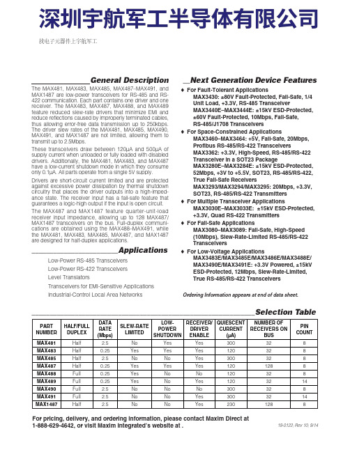
General DescriptionThe MAX481, MAX483, MAX485, MAX487–MAX491, andMAX1487 are low-power transceivers for RS-485 and RS-422 communication. Each part contains one driver and onereceiver. The MAX483, MAX487, MAX488, and MAX489feature reduced slew-rate drivers that minimize E MI andreduce reflections caused by improperly terminated cables,thus allowing error-free data transmission up to 250kbps.The driver slew rates of the MAX481, MAX485, MAX490,MAX491, and MAX1487 are not limited, allowing them totransmit up to 2.5Mbps.These transceivers draw between 120µA and 500µA ofsupply current when unloaded or fully loaded with disableddrivers. Additionally, the MAX481, MAX483, and MAX487have a low-current shutdown mode in which they consumeonly 0.1µA. All parts operate from a single 5V supply.Drivers are short-circuit current limited and are protectedagainst excessive power dissipation by thermal shutdowncircuitry that places the driver outputs into a high-imped-ance state. The receiver input has a fail-safe feature thatguarantees a logic-high output if the input is open circuit.The MAX487 and MAX1487 feature quarter-unit-loadreceiver input impedance, allowing up to 128 MAX487/MAX1487 transceivers on the bus. Full-duplex communi-cations are obtained using the MAX488–MAX491, whilethe MAX481, MAX483, MAX485, MAX487, and MAX1487are designed for half-duplex applications.________________________Applications Low-Power RS-485 Transceivers Low-Power RS-422 Transceivers Level Translators Transceivers for EMI-Sensitive Applications Industrial-Control Local Area Networks__Next Generation Device Features o For Fault-Tolerant Applications MAX3430: ±80V Fault-Protected, Fail-Safe, 1/4Unit Load, +3.3V, RS-485 Transceiver MAX3440E–MAX3444E: ±15kV ESD-Protected,±60V Fault-Protected, 10Mbps, Fail-Safe, RS-485/J1708 Transceivers o For Space-Constrained Applications MAX3460–MAX3464: +5V, Fail-Safe, 20Mbps,Profibus RS-485/RS-422 Transceivers MAX3362: +3.3V, High-Speed, RS-485/RS-422Transceiver in a SOT23 Package MAX3280E–MAX3284E: ±15kV ESD-Protected,52Mbps, +3V to +5.5V, SOT23, RS-485/RS-422,True Fail-Safe Receivers MAX3293/MAX3294/MAX3295: 20Mbps, +3.3V,SOT23, RS-485/RS-422 Transmitters o For Multiple Transceiver Applications MAX3030E–MAX3033E: ±15kV ESD-Protected,+3.3V, Quad RS-422 Transmitters o For Fail-Safe Applications MAX3080–MAX3089: Fail-Safe, High-Speed (10Mbps), Slew-Rate-Limited RS-485/RS-422Transceiverso For Low-Voltage ApplicationsMAX3483E/MAX3485E/MAX3486E/MAX3488E/MAX3490E/MAX3491E: +3.3V Powered, ±15kVESD-Protected, 12Mbps, Slew-Rate-Limited,True RS-485/RS-422 Transceivers For pricing, delivery, and ordering information, please contact Maxim Direct at1-888-629-4642, or visit Maxim Integrated’s website at .______________________________________________________________Selection Table19-0122; Rev 10; 9/14PARTNUMBERHALF/FULL DUPLEX DATA RATE (Mbps) SLEW-RATE LIMITED LOW-POWER SHUTDOWN RECEIVER/DRIVER ENABLE QUIESCENT CURRENT (μA) NUMBER OF RECEIVERS ON BUS PIN COUNT MAX481Half 2.5No Yes Yes 300328MAX483Half 0.25Yes Yes Yes 120328MAX485Half 2.5No No Yes 300328MAX487Half 0.25Yes Yes Yes 1201288MAX488Full 0.25Yes No No 120328MAX489Full 0.25Yes No Yes 1203214MAX490Full 2.5No No No 300328MAX491Full 2.5No No Yes 3003214MAX1487 Half 2.5No No Yes 2301288Ordering Information appears at end of data sheet.找电子元器件上宇航军工MAX481/MAX483/MAX485/MAX487–MAX491/MAX1487Low-Power, Slew-Rate-LimitedRS-485/RS-422 TransceiversPackage Information For the latest package outline information and land patterns, go to . Note that a “+”, “#”, or “-”in the package code indicates RoHS status only. Package drawings may show a different suffix character, but the drawing pertains to the package regardless of RoHS status.16Low-Power, Slew-Rate-Limited RS-485/RS-422 TransceiversMAX481/MAX483/MAX485/MAX487–MAX491/MAX1487Maxim Integrated cannot assume responsibility for use of any circuitry other than circuitry entirely embodied in a Maxim Integrated product. No circuit patent licenses are implied. Maxim Integrated reserves the right to change the circuitry and specifications without notice at any time. The parametric values (min and max limits) shown in the Electrical Characteristics table are guaranteed. Other parametric values quoted in this data sheet are provided for guidance.Maxim Integrated 160 Rio Robles, San Jose, CA 95134 USA 1-408-601-100017©2014 Maxim Integrated Products, Inc.Maxim Integrated and the Maxim Integrated logo are trademarks of Maxim Integrated Products, Inc.。

MAX3483, MAX3485, MAX3486, MAX3488, MAX3490以及MAX3491是用于RS-485与RS-422通信的3.3V,低功耗收发器,每个器件中都具有一个驱动器和一个接收器。
MAX3483和MAX3488具有限摆率驱动器,可以减小EMI,并降低由不恰当的终端匹配电缆引起的反射,实现最高250kbps的无差错数据传输。
MAX3486的驱动器摆率部分受限,可以实现最高2.5Mbps的传输速率。
MAX3485,MAX3490和MAX3491则可以实现最高10Mbps 的传输速率。
驱动器具有短路电流限制,并可以通过热关断电路将驱动器输出置为高阻状态,防止过度的功率损耗。
接收器输入具有失效保护特性,当输入开路时,可以确保逻辑高电平输出。
使用MAX3488, MAX3490和MAX3491可以实现全双工通信,而MAX3483,MAX3485与MAX3486则为半双工应用设计。
这篇文章介绍的就是MAX34852 芯片介绍2.1 主要特点半双工速率:10Mbps限摆率:NO接收允许控制:YES 关断电流:2 nA引脚数:82.2 引脚配置根据上图、上表可知:DE和RO为使能管脚。
DE为低电平、RE为低电平时为接收;DE 为高电平、RE为高电平时为发送;RO和DI为数据管脚。
RO为接收,DI为发送;因此我们经常将DE和RE直接连接,用一个IO口控制(见3.2 电路实现)。
3.1 应用场景工业控制局域网集成服务数字网络低功耗RS-485/RS-422收发器(我做的几个项目都是该功能)分组交换技术电信用于EMI敏感应用的收发器3.2 电路实现485是2线式,两个485接口的设备相连通过A、B两根线即可(也就是至少2个485芯片),连接方式如下图所示:我们使用MAX3485一般是用下图电路:从上图中我们可以看到:RO直接和TTL电平的UART_RX(或模拟串口的RX)相连,DI直接和TTL电平的UART_TX(或模拟串口的TX)相连,R34为1K。


C i r c u i t b r e a k e r sCircuit breakersTeSys GV, GBC ontrol and P rotection C omponentsChapterB60.75g g 1.1g g 1.5375 2.533.5 LR2 K0308GV2LE071.1g g –––––– 2.533.5 LR2 K0308GV2LE071.5g g 1.5g g 3375451 LR2 K0310GV2LE08––– 2.2g g –––451 LR2 K0312GV2LE082.2g g 3501004375 6.378 LR2 K0312GV2LE103g g 410100 5.537510138 LR2 K0314GV2LE144g g 5.510100–––10138 LR2 K0316GV2LE14––––––7.537510138 LRD 14GV2LE14––––––937514170 LRD 16GV2LE165.515507.56751137514170 LR2 K0321GV2LE167.5155096751537518223 LRD 21GV2LE20915401147518.537525327 LRD 22GV2LE2211154015475–––25327 LRD 22GV2LE2215105018.54752237532416LRD 32GV2LE32(1) As % of Icu.g ) > 100 kA.GV2 LE10D F 526144.t i fC i r c u i t b r e a k e r s0.09––––––0.45LRD 03GV2L030.12g g –––0.37g g 0.638LRD 04GV2L040.18g g ––––––0.638LRD 04GV2L04––––––0.55g g 113LRD 05GV2L050.25g g ––––––113LRD 05GV2L05––––––0.75g g 113LRD 06GV2L050.37g g 0.37g g –––113LRD 05GV2L050.55g g 0.55g g 1.1g g 1.622.5LRD 06GV2L06–––0.75g g ––– 1.622.5LRD 06GV2L060.75g g 1.1g g 1.54100 2.533.5LRD 07GV2L07Example: GV3 L32 becomes GV3 L326.(1) As % of Icu. Associated current limiter or fuses, where required. See characteristics page B6/33.g > 100 kA.GV2 L10D F 526145.t i fGV3 L65D F 526146.t i fTeSys GVThermal-magnetic motor circuit breakers GV2 ME0.06gg––––––0.16…0.252.4GV2ME020.09g g––––––0.25…0.405GV2ME030.12 0.18g g g g – –– –– – 0.37 –g–g –0.40…0.638GV2ME040.25gg––– 0.55gg0.63…113GV2ME050.37 0.55 –g g –g g –0.37 0.55 0.75g g g g g g – 0.75 1.1– g g – g g 1…1622.5GV2ME060.75g g1.1gg1.5375 1.6...2.533.5GV2ME071.1 1.5g g g g 1.5 2.2g g g g 2.2 3 3 375 75 2.5 (4)51GV2ME082.2gg350100 43754...6.378GV2ME103 4g g g g 4 5.510 10100 100 5.5 7.5 3 375 756 (10)138GV2ME145.5 –15 –50 –7.5 – 6 –75 – 9 11 3 375 759…14170GV2ME167.5155096751537513…18223GV2ME209154011475 18.537517…23327GV2ME2111154015475 –––20…25327GV2ME22 (3)15105018.54752237524 (32)416GV2ME32Motor circuit breakers from 0.06 to 15 kW / 400 V, with lugsTo order thermal magnetic circuit breakers with connection by lugs, add the digit 6 to the end of reference selected above.Example: GV2 ME08 becomes GV2 ME086.Thermal magnetic circuit breakers GV2 ME with built-in auxiliary contact block With instantaneous auxiliary contact block (composition, see page B6/11):b GV AE1, add suffix AE1TQ to the motor circuit breaker reference selected above. Example: GV2 ME01AE1TQ .b GV AE11, add suffix AE11TQ to the motor circuit breaker reference selected above. Example: GV2 ME01AE11TQ .b GV AN11, add suffix AN11TQ to the motor circuit breaker reference selected above. Example: GV2 ME01AN11TQ .These circuit breakers with built-in contact block are sold in lots of 20 units in a single pack.(1) As % of Icu.(2) The thermal trip setting must be within the range marked on the graduated knob.(3) Maximum rating which can be mounted in enclosures GV2 MC or MP , please consult your Regional Sales Office. g > 100 kA.GV2 ME10D F 526134.t i fC i r c u i t b r e a k e r sTeSys GVTeSys protection componentsThermal-magnetic motor circuit breakers GV2 MEReferences0.06g g ––– 0.16…0.25 2.4GV2ME0230.09g g ––– 0.25…0.405GV2ME0330.120.18g g g g –––0.40…0.638GV2ME0430.250.37g g g g 0.37g g 0.63…113GV2ME0530.370.55g g g g 0.370.550.75g g g g g g 1…1.622.5GV2ME0630.75g g1.1g g 1.6…2.533.5GV2ME0731.11.5g g g g 1.52.2g g g g 2.5…451GV2ME0832.2g g 350100 4…6.378GV2ME10334g g g g 45.510101001006…10138GV2ME1435.515507.5675 9…14170GV2ME1637.515509675 13…18223GV2ME203911151540401147517…23327GV2ME2131115401547520 (25)327GV2ME223Contact blocksDescription Mounting Maximum number Type of contacts Sold in lots of Unitreference Instantaneous auxiliary contactsFront 1N/O + N/C 10GVAE113N/O + N/O 10GVAE203LH side2N/O + N/C 1GVAN113N/O + N/O1GVAN203AccessoryDescriptionApplicationSold in lots of Unitreference Cable end reducerFor connection of conductors from 1 to 1.5 mm 220LA9D99(1) For connection of conductors from 1 to 1.5 mm 2, the use of an LA9 D99 cable end reducer is recommended.(2) Maximum rating which can be mounted in enclosures GV2 MC or MP , please consult your Regional Sales Office (3) The thermal trip setting must be within the range marked on the graduated knob.g > 100 kA.GV2 ME pp 3D F 526135.t i fLA9 D99D F 533898.e p sTeSys GVReferencesTeSys protection componentsThermal-magnetic motor circuit breakersGV2 P, GV3 P and GV3 ME80GV2 P10D F 526137.t i fGV3 P65D F 526139.t i fGV3 P651D F 526140.t i fC i r c u i t b r e a k e r sTeSys GVReferences93610011181001581007.59707010010091150501001001115101010010012…20GV7RS20 2.0109113636100100111518181001001518.58810010015…25GV7RE25 2.0109117070100100111550501001001518.5101010010015…25GV7RS25 2.01018.53610018.522181810010022810025…40GV7RE40 2.01018.57010018.550100221010025…40GV7RS40 2.0102236100301810030810030…50GV7RE50 2.01522701003050100301010030 (50)GV7RS502.01537361004555181810010055810048...80GV7RE80 2.040377010045555050100100551010048...80GV7RS80 2.0404536100–1810075810060...100GV7RE100 2.0404570100–50100751010060...100GV7RS100 2.0405575353510010075903030100100901108810010090 (150)GV7RE1502.020557570701001007590505010010090110101010010090…150GV7RS150 2.02090110353510010011013216030303010010010016020088100100132…220GV7RE220 2.3509011070701001001101321605050501001001001602001010100100132…220GV7RS220 2.350(1) As % of lcu.TeSys protection componentsThermal-magnetic motor circuit breakers GV7 RGV7 RE40D F 526138.t i fGV7 RS220D F 526141.t i f0.12–0.120.180.18–0.370.40…0.6313GV2RT040.090.120.250.370.250.370.370.550.63…122GV2RT050.180.250.370.550.370.550.370.550.750.751.11…1.633GV2RT060.370.750.751.1 1.11.51.6…2.551GV2RT070.550.75 1.11.5 1.51.52.2 2.23 2.5…478GV2RT081.12.22.23344…6.3138GV2RT101.52.234445.5 5.57.56…10200GV2RT142.23 5.55.57.57.59119…14280GV2RT1647.57.5991513…18400GV2RT205.5911111118.517…23400GV2RT21(1) The thermal trip setting must be within the range marked on the graduated knob.GV2 RTD F 526142.t i fC i r c u i t b r e a k e r sblack handle, blue legend plate(1) The thermal trip setting must be within the range marked on the graduated knob.(2) Other accessories such as mounting, cabling and marking accessories are identical to those used for GV2 ME motor circuit breakers, see page B6/13.GV2 RTD F 526142.t i fD F 526340.e p sC i r c u i t b r e a k e r sTeSys GVDescription Mounting Maximum number Type of contacts Sold inlots of Unitreference Instantaneous auxiliary contactsFront (1)1N/O or N/C (2)10GVAE1N/O + N/C 10GVAE11N/O + N/O10GVAE20Side (LH)2N/O + N/C1GVAN11N/O + N/O1GVAN20Fault signalling contact + instantaneous auxiliary contact Side (3) (LH)1N/O (fault)+ N/O1GVAD1010+ N/C1GVAD1001N/C (fault)+ N/O1GVAD0110+ N/C1GVAD0101Short-circuit signalling contactSide (LH)1C/O common point1GVAM11(1 block on RH sideof circuit breaker GV2 ME)50 Hz GVAX11560 Hz GVAX116127 V60 Hz GVAX115220…240 V 50 Hz GVAX22560 Hz GVAX226380…400 V50 Hz GVAX38560 Hz GVAX386415…440 V 50 Hz GVAX415440 V60 Hz GVAX385Add-on contact blocksDescriptionMountingMaximum number Reference Visible isolation block (5)Front (1)1GV2AK00 (6)LimitersAt top(GV2 ME and GV2 P)1GV1L3Independent1LA9LB920(1) Mounting of a GV AE contact block or a GV2 AK00 visible isolation block on GV2 P and GV2 L .(2) Choice of N/C or N/O contact operation, depending on which way round the reversible block is mounted.(3) The GV AD is always mounted next to the circuit breaker.(4) To order an undervoltage trip: replace the dot (p ) in the reference with a U , example: GV AU025. To order a shunt trip: replace the dot (p ) in the reference with an S , example: GV AS025.(5) Visible isolation of the 3 poles upstream of circuit breaker GV2 P and GV2 L .Visible isolation block GV2 AK00 cannot be used with motor circuit breakers GV2 P32 and GV2 L32 (Ith max = 25 A).(6) Ie Max = 32 A.ReferencesTeSys protection componentsThermal-magnetic and magnetic motor circuit breakers GV2 with screw clamp connectionsAdd-on blocks and accessoriesCharacteristics:pages B6/89 and B6/94Dimensions, schemes:pages B6/70 to B6/82LA9LB920D B 126629.e p sC i r c u i t b r e a k e r sTeSys GVTerminal blockfor supply to one or more GV2 G busbar setsConnection from the top1GV1G09Can be fitted with current limiter GV1 L3 (GV2 ME and GV2 P)1GV2G05Cover for terminal block For mounting in modular panels10LA9E07Flexible 3-pole connection for connecting a GV2 to a contactor LC1-D09…D25 Centre distance between mounting rails: 100…120 mm10GV1G02Set of connections upstream/downstream For connecting GV2 ME to a printed circuit board 10GV2GA01“Large Spacing” adapter UL 508 type EFor GV2 P pp H7 (except 32 A)1GV2GH7Clip-in marker holders (supplied with each circuit breaker)For GV2 P , GV2 L, GV2 LE and GV2 RT (8 x 22 mm)100LA9D92ReferencesTeSys protection componentsThermal-magnetic and magnetic motor circuit breakers GV2 with screw clamp connectionsAccessoriesDimensions, schemes:pages B6/70 to B6/82D B 417942.e p sTeSys GVD B 126631.e p sD B 126630.e p sD B 126632.e p s7P B 106297_45.e p sExtended Rotary HandleAllows a circuit breaker or a starter-controller installed in back of an enclosure to be operated from the front of the enclosure.A rotary handle can be black or red/yellow, IP54 or IP65. It includes a function for locking the circuit breaker or the starter in the O (Off) or I (On) position(depending of the type of rotary handle) by means of up to 3 padlocks with a shank diameter of 4 to 8 mm. The extended shaft must be adjusted to use in different size enclosures. The IP54 rotary handle is fixed with a nut (Ø22) to make easierthe assembling. The new Laser Square tool brings the accuracy to align the circuit breaker and the rotary handle.device(padlocks not included)ReferencesTeSys protection componentsThermal-magnetic and magnetic motor circuit breakers GV2 with screw clamp connectionsC i r c u i t b r e a k e r sTeSys GVDescriptionMounting Maximum number Type of contacts Sold inlots of Unitreference Instantaneous auxiliary contactsFront1N/O or N/C (1)10GVAE1N/O + N/C 10GVAE11 (2)N/O + N/O10GVAE20 (2)Side (LH)2N/O + N/C1GVAN11 (2)N/O + N/O1GVAN20 (2)Fault signalling contact + instantaneous auxiliary contactFront 1N/O (fault)+ N/O1GVAED101 (2)N/O (fault)+ N/C1GVAED011 (2)Side (3) (LH)1N/O (fault)+ N/O1GVAD1010+ N/C1GVAD1001N/C (fault)+ N/O1GVAD0110+ N/C1GVAD0101Short-circuit signalling contact Side (LH)1C/O common point 1GVAM11(4)MountingVoltage ReferenceSide(1 block on RH side of circuit breaker)24 V 50 Hz GVA p 02560 Hz GVA p 02648 V 50 Hz GVA p 05560 Hz GVA p 05610050 Hz GVA p 107100…110 V 60 Hz GVA p 107110…115 V 50 Hz GVA p 11560 Hz GVA p 116120…127 V 50 Hz GVA p 125127 V 60 Hz GVA p 115200 V50 Hz GVA p 207200…220 V 60 Hz GVA p 207220…240 V 50 Hz GVA p 22560 Hz GVA p 226380…400 V 50 Hz GVA p 38560 Hz GVA p 386415…440 V 50 Hz GVA p 415415 V 60 Hz GVA p 416440 V 60 Hz GVA p 385480 V 60 Hz GVA p 415500 V 50 Hz GVA p 505600 V60 HzGVA p 505AccessoriesDescription Reference Sets of 3-pole 115 A busbars Pitch: 64 mm2 tap-off GV3 P pp and GV3 L pp GV3G2643 tap-off GV3 P pp and GV3 L pp GV3G364Cover “Large Spacing” UL 508 type E (Only one cover required on supply side)GV3 P ppGV3G66(1) Choice of N/C or N/O contact operation, depending on which way round the reversible block is mounted.(2) Contact blocks available in version with spring terminal connections. Add a figure 3 at the end of the references selected above. Example: GV AED101 becomes GV AED1013.(3) The GV AD pp is always mounted next to the circuit breaker.(4) To order an undervoltage trip: replace the dot (p ) in the reference with a U , example: GV AU025. To order a shunt trip: replace the dot (p ) in the reference with an S , example: GV AS025.Add-on blocks and accessoriesGV3 G66D F 537424.e p sTeSys GVD B 126637.e p sD B 126636.e p sD B 126632.e p s7P B 106297_45.e p sExtended Rotary HandleAllows a circuit breaker or a starter-controller installed in back of an enclosure to be operated from the front of the enclosure.A rotary handle can be black or red/yellow, IP54 or IP65. It includes a function for locking the circuit breaker or the starter in the O (Off) or I (On) position(depending of the type of rotary handle) by means of up to 3 padlocks with a shank diameter of 4 to 8 mm. The extended shaft must be adjusted to use in different size enclosures. The IP54 rotary handle is fixed with a nut (Ø22) to make easierthe assembling. The new Laser Square tool brings the accurency to align the circuit breaker and the rotary handle.For English 10-GVAPSEN For German 10-GVAPSDE For Spanish10-GVAPSES For Chinese 10-GVAPSCN For Portuguese 10-GVAPSPT For Russian 10-GVAPSRU For Italian10-GVAPSITD F 526342.e p sB6/21C i r c u i t b r e a k e r sTeSys GVfor locking the Start button (on open-mounted product)using up to 3 padlocks(padlocks to be ordered separately)External operator for mounting on enclosure door.Red Ø40 knob on yellow plate, padlockable in position O (with up to 3 padlocks). Door locked when knob in position I, and when knob padlocked in position O.GK3AP03(1) 1 voltage trip OR 1 fault signalling contact to be fitted inside the motor circuit breaker.Other versions24 to 690 V, 50 or 60 Hz voltage trips for circuit breakers GV3 ME80.Please consult your Regional Sales Office.ReferencesTeSys protection componentsMotor circuit breakers GV3 ME80 and GK3 EF80Add-on blocks and accessoriesCharacteristics:pages B6/89 and B6/92Dimensions:page B6/47B6/22D F 526344.e p sB6/23C i r c u i t b r e a k e r sTeSys GVThese allow remote indication of the circuit breaker contact states. They can be used for signalling, electrical locking, relaying, etc. They are available in two versions: standard and low level. They include a terminal block and the auxiliary circuits leave the circuit breaker through a hole provided for this purpose.They perform the following functions, depending on where they are located in the circuit breaker:Low levelGV7AB11Fault discrimination devicesThese make it possible to:b either differentiate a thermal fault from a magnetic fault,b or open the contactor only in the event of a thermal fault.VoltageReference a 24...48 and c 24…72 V GV7AD111 (1)z 110…240 VGV7AD112 (1)Electric tripsThese allow the circuit breaker to be tripped via an electrical control signal.b Undervoltage trip GV7 AUv Trips the circuit breaker when the control voltage drops below the tripping threshold, which is between 0.35 and 0.7 times the rated voltage.v Circuit breaker closing is only possible if the voltage exceeds 0.85 times the rated voltage. Circuit breaker tripping by a GV7 AU trip meets the requirements of IEC 60947-2.b Shunt trip GV7 ASTrips the circuit breaker when the control voltage rises above 0.7 times the rated voltage.b Operation (GV7 AU or GV7 AS)v When the circuit breaker has been tripped by a GV7 AU or AS, it must be reset either locally or by remote control. (For remote control, please consult your Regional Sales Office).v Tripping has priority over manual closing: if a tripping instruction is present, manual action does not result in closing, even temporarily, of the contacts.v Durability: 50 % of the mechanical durability of the circuit breaker.TypeVoltageReference Undervoltage trip48 V, 50/60 HzGV7AU055 (1)110…130 V, 50/60 Hz GV7AU107 (1)200…240 V, 50/60 Hz GV7AU207 (1)380…440 V, 50/60 Hz GV7AU387 (1)525 V, 50 HzGV7AU525 (1)Shunt trip48 V, 50/60 HzGV7AS055 (1)110…130 V, 50/60 Hz GV7AS107 (1)200…240 V, 50/60 Hz GV7AS207 (1)380…440 V, 50/60 Hz GV7AS387 (1)525 V, 50 HzGV7AS525 (1)(1) For mounting of a GV7 AD or a GV7 AU or AS.ReferencesTeSys protection componentsThermal-magnetic motor circuit breakers GV7 R with screw clamp connectionsAdd-on blocks and accessoriesCharacteristics:pages B6/51, B6/52 and B6/56Dimensions:pages B6/79 to B6/81Schemes:page B6/83B6/24B6/25C i r c u i t b r e a k e r sTeSys GVDescription ApplicationFor use on contactors Sold in lots of Unitreference Clip-on connectors for GV7 RUp to 150 A, 1.5…95 mm 2–3GV7AC021Up to 220 A, 1.5…185 mm 2–3GV7AC022Spreader 3-pole (1)To increase the pitch to 45 mm–1GV7AC03Terminal shields IP 405 (1)Supplied with sealing accessory–1GV7AC01Phase barriersSafety accessories used when fitting of shields is impossible –2GV7AC04Insulating screens Ensure insulation between the connections and the backplate –2GV7AC05Kits for combination with contactor (2)Allowing link between thecircuit breaker and the contactor. The cover provides protection against direct finger contactLC1 F115…F1851GV7AC06LC1 F225 and F2651GV7AC07LC1 D115 and D1501GV7AC08Replaces the circuit breaker front cover; secured by screws. It includes a device for locking the circuit breaker in the O (Off) position by means of up to 3 padlocks with a shank diameter of 5 to 8 mm (padlocks not included). A conversion accessory allows the direct rotary handle to be mounted on the enclosure door. In this case, the door cannot be opened if the circuit breaker is in the “ON” position. Circuit breaker closing is inhibited if the enclosure door is open.Description TypeDegree of protection Reference Direct rotary handleBlack handle, black legend plate IP 40GV7AP03Red handle, yellow legend plateIP 40GV7AP04Adapter plate (3)Four mounting direct rotary handle on enclosure doorIP 43GV7AP05Allows a circuit breaker installed in the back of an enclosure to be operated from the front of the enclosure. It comprises:b a unit which screws onto the front cover of the circuit breaker,b an assembly (handle and front plate) to be fitted on the enclosure door,b an extension shaft which must be adjusted (distance between the mounting surface and the door: 185 mm minimum, 600 mm maximum). It includes a device for locking the circuit breaker in the O (Off) position by means of up to 3 padlocks with a shank diameter of 5 to 8 mm (padlocks not included). This prevents the enclosure door from being opened.DescriptionTypeDegree of protection Reference Extended rotary handleBlack handle, black legend plate IP 55GV7AP01Red handle, yellow legend plateIP 55GV7AP02Allows circuit breakers not fitted with a rotary handle to be locked in the O (Off) position by means of up to 3 padlocks with a shank diameter of 5 to 8 mm (padlocks not included).Description ApplicationReference Locking deviceFor circuit breaker not fitted with a rotary handleGV7V01(1) Terminal shields cannot be used together with spreaders.(2) The kit comprises links, a protective shield and a depth adjustable metal bracket for the breaker.(3) This conversion accessory makes it impossible to open the door if the device is closed and prevents the device from being closed if the door is open.ReferencesTeSys protection componentsThermal-magnetic motor circuit breakers GV7 R with screw clamp connectionsAccessoriesGV7 AC07D F 537429.e p sGV7 AC08D F 537428.e p sDimensions:pages B6/79 to B6/81B6/260.5 6.63GB2DB051143GB2DB062263GB2DB073403GB2DB084503GB2DB095663GB2DB106833GB2DB1281083GB2DB14101383GB2DB16121653GB2DB20162203GB2DB21202703GB2DB22(1) Conforming to IEC 60947-1.GB2 CBppD F 526243.t i fGB2 CD ppD F 526244.t i fGB2 DBppD F 526245.t i fPresentation, selection :page B6/84Characteristics :pages B6/85 to B6/87Dimensions :page B6/88Schemes :page B6/88B6/27C i r c u i t b r e a k e r s(1) Conforming to IEC 60947-1.Accessories for circuit breakers GB2-CB, DB and CSDescriptionSold in lots of Unitreference Busbar set for supply to 10 GB2 DB or20 GB2 CB or GB2 CS with 2 connectors1GB2G210Supply connector 10GB2G01GB2 CS ppD F 526246.t i fPresentation, selection :page B6/84Characteristics :pages B6/85 to B6/87Dimensions :page B6/88Schemes :page B6/88B6/28B6/29B6/30TeSys GVCharacteristicsTeSys protection componentsMagnetic motor circuit breakers GV2 LE and GV2 LReferences:pages B6/2 and B6/3Dimensions:pages B6/43 to B6/47Schemes:page B6/48add-on contact blocks. Side by side mounting is possible up to 40 °C.(2) When mounting on a vertical rail, fit a stop to prevent any slippage.(1) As % of Icu.Average operating times at 20 °C related to multiples of the setting currentD F 534092.e p s1 3 poles from cold state2 2 poles from cold state3 3 poles from hot stateDynamic stressI peak = f (prospective Isc) at 1.05 Ue = 435 VD F 534093.e p s1 Maximum peak current2 32 A3 25 A4 18 A5 14 A6 10 A7 6.3 A8 4 A9 2.5 A 10 1.6 A11 Limit of rated ultimate breaking capacity on short-circuit of GV2 LE (14, 18, 23 and 25 A ratings).Dynamic stressI peak = f (prospective Isc) at 1.05 Ue = 435 VD F 534094.e p s1 Maximum peak current2 32 A3 25 A4 18 A5 14 A6 10 A7 6.3 A8 4 A9 2.5 A 10 1.6 A11 Limit of rated ultimate breaking capacity on short-circuit of GV2 LE (14, 18, 23 and 25 A ratings).Thermal limit in kA 2s in the magnetic operating zone Sum of I 2dt = f (prospective Isc) at 1.05 Ue = 435 V22Prospective Isc (kA)D F 534095.e p s1 32 A 2 25 A3 18 A4 14 A5 10 A6 6.3 A7 4 A8 2.5 A9 1.6 AThermal limit in kA 2s in the magnetic operating zone Sum of I 2dt = f (prospective Isc) at 1.05 Ue = 435 V22D F 534096.e p s1 25 A and 32 A 2 18 A3 14 A 4 10 A5 6.3 A6 4 A7 2.5 A8 1.6 AThermal limit in kA 2s in the magnetic operating zone Sum of I 2dt = f (prospective Isc) at 1.05 Ue = 435 V22D F 534097.e p s1 32 A (GV2 LE32)2 25 A and 32 A (GV2 L32)3 18 A4 14 A5 10 A6 6.3 A7 4 A8 2.5 A9 1.6 A10 Limit of rated ultimate breaking capacity on short-circuit of GV2 LE (14, 18, 23 and 25 A ratings).Average operating time at 20 °C without prior current flowx the setting current (Ir)D F 534098.e p s1 3 poles from cold state2 2 poles from cold state3 3 poles from hot stateA Thermal overload relay protection zoneB GV3 L protection zoneDynamic stressI peak = f (prospective Isc) at 1.05 Ue = 435 VProspective Isc (kA)D B 418280.e p s1 Maximum peak current2 GV3 L653 GV3 L504 GV3 L405 GV3 L326 GV3 L25Thermal limit in A 2sSum of I 2dt = f (prospective Isc) at 1.05 Ue = 435 V2Prospective Isc (kA)D B 418279.e p s1 GV3 L652 GV3 L503 GV3 L404 GV3 L325 GV3 L25TeSys GVDimensions, mountingD F 537440.e p sD F 537441.e p sD F 537444.e p sTeSys protection componentsMagnetic motor circuit breakers GV2 L and GV2 LETeSys GVDimensions, mounting TeSys protection componentsMagnetic motor circuit breakers GV2 L and GV2 LED B 127415.e p sD B 127414.e p sa b Mini Maxi Mini Maxi GV2 APN pp140250GV2 APN pp + GV APH02151250GV2 APN pp + GV APK11250434--GV2 APN pp + GV APH02 + GV APK11--250445TeSys GVDimensions,mounting Sets of busbars GV2 G445, GV2 G454, GV2 G472, with terminal block GV2 G05D F 537451.e p sGV2 G445224269314359GV2 G454260314368422GV2 G472332404476548D F 537452.e p sD F 537454.e p sGV2 G345 (3 x 45 mm)134GV2 G354 (3 x 54 mm)152TeSys protection componentsMagnetic motor circuit breakers GV2 L and GV2 LED F 537480.e psD F 537435.e p sD F 510637.e p sD F 510638.e p sD B 127416.e p sD B 127417.e p sa b Mini Maxi Mini Maxi GV3 APN pp189300--GV3 APN pp + GV APK12300481GV3 APN pp + GV APH03--200300GV3 APN pp + GV APH03 + GV APK12--300492TeSys GVSchemesTeSys protection componentsMagnetic motor circuit breakers GV2 L, GV2 LE, GV3 LD F 537474.e p sD F 537475.e p sD F 537476.e p sGV2 ME, GV2 P , GV3 ME, GV3 P and GV7 R motor circuit breakers are 3-pole thermal-magnetic circuit breakers specifically designed for the control and protection of motors , conforming to standards IEC 60947-2 and IEC 60947-4-1.Connection GV2GV2 ME and GV2 P circuit breakers are designed for connection by screw clamp terminals.Circuit breaker GV2 ME can be supplied with lugs or spring terminal connections.Spring terminal connections ensure secure, permanent and durable clamping that is resistant to harsh environments, vibration and impact and are even more effective when conductors without cable ends are used. Each connection can take two independent conductors.GV3GV3 circuit breakers feature connection by BTR screws (hexagon socket head), tightened using a n° 4 Allen key.This type of connection uses the Ever Link ® system with creep compensation (1) (Schneider Electric patent).This technique makes it possible to achieve accurate and durable tightening torque, in order to avoid cable creep.GV3 circuit breakers are also available with connection by lugs. This type of connection meets the requirements of certain Asian markets and is suitable for applications subject to strong vibration, such as railway transport.GV7GV7 circuit breakers: with connection by screw clamp terminals (for bars and lugs) and by clip-on connectors.OperationControl is manual and local when the motor circuit breaker is used on its own.Control is automatic and remote when it is associated with a contactor.GV2 ME and GV3 ME80Pushbutton control.Energisation is controlled manually by operating the Start button “I” 1.De-energisation is controlled manually by operating the Stop button “O” 2, or automatically by the thermal-magnetic protection elements or by a voltage trip attachment.GV2 P , GV3 P and GV7 Rb Control by rotary knob: for GV2 P and GV3 P b Control by rocker lever: for GV7 R.Energisation is controlled manually by moving the knob or rocker lever to position “I” 1.De-energisation is controlled manually by moving the knob or rocker lever to position “O” 2.De-energisation due to a fault automatically places the knob or rocker lever in the “Trip” position 3.Re-energisation is possible only after having returned the knob or rocker lever to position “O”.(1) Creep: normal crushing phenomenon of copper conductors, that is accentuated over time.GV2 MEwith screw clamp terminals124D F 526134.t i fGV2 MEwith spring terminals connections124D F 526135.t i fGV3 P1324D F 526136.t ifGV2 P1342D F 526137.t i fGV7 R132D F 526138.t i f。

General DescriptionThe MAX4080/MAX4081 are high-side, current-sense amplifiers with an input voltage range that extends from 4.5V to 76V making them ideal for telecom, automotive,backplane, and other systems where high-voltage cur-rent monitoring is critical. The MAX4080 is designed for unidirectional current-sense applications and the MAX4081 allows bidirectional current sensing. The MAX4081 single output pin continuously monitors the transition from charge to discharge and avoids the need for a separate polarity output. The MAX4081requires an external reference to set the zero-current output level (V SENSE = 0V). The charging current is rep-resented by an output voltage from V REF to V CC , while discharge current is given from V REF to GND.For maximum versatility, the 76V input voltage range applies independently to both supply voltage (V CC )and common-mode input voltage (V RS+). H igh-side current monitoring does not interfere with the ground path of the load being measured, making the MAX4080/MAX4081 particularly useful in a wide range of high-voltage systems.The combination of three gain versions (5V/V, 20V/V,60V/V = F, T, S suffix) and a user-selectable, external sense resistor sets the full-scale current reading and its proportional output voltage. The MAX4080/MAX4081offer a high level of integration, resulting in a simple,accurate, and compact current-sense solution.The MAX4080/MAX4081 operate from a 4.5V to 76V sin-gle supply and draw only 75µA of supply current. These devices are specified over the automotive operating temperature range (-40°C to +125°C) and are available in a space-saving 8-pin µMAX or SO package.ApplicationsAutomotive (12V, 24V, or 42V Batteries)48V Telecom and Backplane Current MeasurementBidirectional Motor Control Power-Management SystemsAvalanche Photodiode and PIN-Diode Current MonitoringGeneral System/Board-Level Current Sensing Precision High-Voltage Current SourcesFeatures♦Wide 4.5V to 76V Input Common-Mode Range ♦Bidirectional or Unidirectional I SENSE ♦Low-Cost, Compact, Current-Sense Solution ♦Three Gain Versions Available5V/V (MAX4080F/MAX4081F)20V/V (MAX4080T/MAX4081T)60V/V (MAX4080S/MAX4081S)♦±0.1% Full-Scale Accuracy ♦Low 100µV Input Offset Voltage ♦Independent Operating Supply Voltage ♦75µA Supply Current (MAX4080)♦Reference Input for Bidirectional OUT (MAX4081)♦Available in a Space-Saving 8-Pin µMAX PackageMAX4080/MAX408176VVoltage Output________________________________________________________________Maxim Integrated Products 1Pin ConfigurationsOrdering Information19-2562; Rev 0; 10/02For pricing, delivery, and ordering information, please contact Maxim Direct at 1-888-629-4642,or visit Maxim’s website at .Selector Guide appears at end of data sheet.M A X 4080/M A X 408176V , High-Side, Current-Sense Amplifiers with Voltage Output 2_______________________________________________________________________________________ABSOLUTE MAXIMUM RATINGSStresses beyond those listed under “Absolute Maximum Ratings” may cause permanent damage to the device. These are stress ratings only, and functional operation of the device at these or any other conditions beyond those indicated in the operational sections of the specifications is not implied. Exposure to absolute maximum rating conditions for extended periods may affect device reliability.V CC to GND............................................................-0.3V to +80V RS+, RS- to GND....................................................-0.3V to +80V OUT to GND.............-0.3V to the lesser of +18V or (V CC + 0.3V)REF1A, REF1B to GND(MAX4081 Only)....-0.3V to the lesser of +18V or (V CC + 0.3V)Output Short Circuit to GND.......................................Continuous Differential Input Voltage (V RS + - V RS -)...............................±80V Current into Any Pin..........................................................±20mAContinuous Power Dissipation (T A = +70°C)8-Pin µMAX (derate 4.5mW/°C above +70°C).............362mW 8-Pin SO (derate 5.88mW/°C above +70°C)................471mW Operating Temperature Range .........................-40°C to +125°C Junction Temperature......................................................+150°C Storage Temperature Range.............................-65°C to +150°C Lead Temperature (soldering, 10s).................................+300°CDC ELECTRICAL CHARACTERISTICSMAX4080/MAX408176V , High-Side, Current-Sense Amplifiers withVoltage Output_______________________________________________________________________________________3DC ELECTRICAL CHARACTERISTICS (continued)M A X 4080/M A X 408176V , High-Side, Current-Sense Amplifiers with Voltage Output 4_______________________________________________________________________________________AC ELECTRICAL CHARACTERISTICSNote 2:V REF is defined as the average voltage of V REF1A and V REF1B . REF1B is usually connected to REF1A or GND.V SENSE is defined as V RS+- V RS-.Note 3:The common-mode range at the low end of 4.5V applies to the most positive potential at RS+ or RS-. Depending on thepolarity of V SENSE and the device’s gain, either RS+ or RS- can extend below 4.5V by the device’s typical full-scale value of V SENSE .Note 4:Negative V SENSE applies to MAX4081 only.Note 5:V SENSE is:MAX4080F, 10mV to 1000mV MAX4080T, 10mV to 250mV MAX4080S, 10mV to 100mV MAX4081F, -500mV to +500mV MAX4081T, -125mV to +125mV MAX4081S, -50mV to +50mVNote 6:V OS is extrapolated from the gain accuracy test for the MAX4080 and measured as (V OUT - V REF )/A V at V SENSE = 0V, for theMAX4081.Note 7:V SENSE is:MAX4080F, 500mV MAX4080T, 125mV MAX4080S, 50mV MAX4081F/T/S, 0VV REF1B = V REF1A = 2.5VNote 8:Output voltage is internally clamped not to exceed 18V.Note 9:Output settles to within 1% of final value.Note 10:The device will not experience phase reversal when overdriven.MAX4080/MAX408176V , High-Side, Current-Sense Amplifiers withVoltage Output_______________________________________________________________________________________52015105302535-125-75-50-25-1000255075100125INPUT OFFSET VOLTAGE HISTOGRAMINPUT OFFSET VOLTAGE (μV)P E R C E N T A G E (%)INPUT OFFSET VOLTAGE vs. TEMPERATURE-300-250-150-200050-50-100300100150200250I N P U T O F F S E T V O L T A G E (μV )-502550-2575100125150TEMPERATURE (°C)-0.5-0.2-0.3-0.40-0.10.40.30.20.10.5-50-250255075100125GAIN ACCURACY vs. TEMPERATURETEMPERATURE (°C)G A I N A C C U R A C Y (%)GAIN ACCURACY vs. V CCV CC (V)G A I N A C C U R A C Y (%)6452402816-0.15-0.10-0.05-0.20476M A X 4080 t o c 05FREQUENCY (Hz)C O M M O N -M ODE R E J E C T I O N R A T I O (d B )100k10k1k10010-120-100-110-90-80-60-70-50-40-20-30-100-13011M MAX4081F/T/SCOMMON-MODE REJECTION RATIOvs. FREQUENCYM A X 080 t o c 06FREQUENCY (Hz)P O W E R -S U P P L Y R E J E C T I O N R A T I O (d B )100k 10k 1k 10010-120-100-110-90-80-60-70-50-40-20-30-100-13011MMAX4081F/T/SPOWER-SUPPLY REJECTION RATIOvs. FREQUENCYM A X 4080 t o c 07FREQUENCY (Hz)R E F E R E N C E R E J E C T I O N R A T I O (dB )-110-90-100-80-60-70-50-40-20-30-100-120MAX4081F/T/SREFERENCE REJECTION RATIOvs. FREQUENCY10k1k100101100k FREQUENCY (kHz)G A I N (d B )100101510152025303540455000.11000MAX4080F/T/SSMALL-SIGNAL GAIN vs. FREQUENCYFREQUENCY (kHz)G A I N (d B )10010151015202530354045500.11000MAX4081F/T/SSMALL-SIGNAL GAIN vs. FREQUENCYTypical Operating Characteristics(V CC = V RS+= 48V, V SENSE = 0V, C LOAD = 20pF, R LOAD = ∞, T A = +25°C, unless otherwise noted.)M A X 4080/M A X 408176V , High-Side, Current-Sense Amplifiers with Voltage Output 6_______________________________________________________________________________________Typical Operating Characteristics (continued)(V CC = V RS+= 48V, V SENSE = 0V, C LOAD = 20pF, R LOAD = ∞, T A = +25°C, unless otherwise noted.)6065757080854281640526476MAX4080SUPPLY CURRENT vs. V CCV CC (V)S U P P L Y C U R R E N T (μA )V CC (V)S U P P L Y C U R R E N T (μA )6452162840859095100105110115120125476MAX4081SUPPLY CURRENT vs. V CC65807570908511010510095115-50-250255075100125MAX4080SUPPLY CURRENT vs. TEMPERATUREM A X 4080 t o c 12TEMPERATURE (°C)S U P P L Y C U R RE N T (μA )65807570908511010510095115-50-250255075100125MAX4081SUPPLY CURRENT vs. TEMPERATURETEMPERATURE (°C)S U P P L Y C U R R E N T (μA )I OUT (SOURCING) (mA)V O U T H I G H V O L T A G E (V C C - V O H ) (V )0.90.80.60.70.20.30.40.50.10.050.100.150.200.250.300.350.400.450.5001.0V OUT HIGH VOLTAGE vs. I OUT (SOURCING)450400350300250200150100505010015020025030000500V OUT LOW VOLTAGE vs. I OUT (SINKING)I OUT (SINKING) (μA)V O U T L O W V O L T A G E (m V )MAX4080 toc16INPUT 5mV/div OUTPUT 25mV/div 20μs/div MAX4080FSMALL-SIGNAL TRANSIENT RESPONSEMAX4080 toc17INPUT 5mV/div OUTPUT 100mV/div 20μs/div MAX4080TSMALL-SIGNAL TRANSIENT RESPONSEMAX4080 toc18INPUT 5mV/divOUTPUT 300mV/div20μs/divMAX4080SSMALL-SIGNAL TRANSIENT RESPONSEMAX4080/MAX408176V , High-Side, Current-Sense Amplifiers withVoltage Output_______________________________________________________________________________________7MAX4080 toc19INPUT 10mV/div OUTPUT 50mV/div 20μs/div MAX4081FSMALL-SIGNAL TRANSIENT RESPONSEMAX4080 toc20INPUT 2.5mV/div OUTPUT 50mV/div 20μs/div MAX4081TSMALL-SIGNAL TRANSIENT RESPONSEMAX4080 toc21INPUT 1mV/divOUTPUT 50mV/div20μs/divMAX4081SSMALL-SIGNAL TRANSIENT RESPONSEMAX4080 toc22INPUT 400mV/div OUTPUT 2V/div 20μs/div MAX4080FLARGE-SIGNAL TRANSIENT RESPONSEMAX4080 toc23INPUT 100mV/div OUTPUT 2V/div 20μs/div MAX4080TLARGE-SIGNAL TRANSIENT RESPONSEMAX4080 toc24INPUT 33mV/divOUTPUT 2V/div20μs/divMAX4080SLARGE-SIGNAL TRANSIENT RESPONSEMAX4080 toc25INPUT 400mV/div OUTPUT 2V/div 20μs/div MAX4081FLARGE-SIGNAL TRANSIENT RESPONSEMAX4080 toc26INPUT 100mV/div OUTPUT 2V/div 20μs/div MAX4081TLARGE-SIGNAL TRANSIENT RESPONSEMAX4080 toc27INPUT 33mV/divOUTPUT 2V/div20μs/divMAX4081SLARGE-SIGNAL TRANSIENT RESPONSETypical Operating Characteristics (continued)(V CC = V RS+= 48V, V SENSE = 0V, C LOAD = 20pF, R LOAD = ∞, T A = +25°C, unless otherwise noted.)M A X 4080/M A X 408176V , High-Side, Current-Sense Amplifiers with Voltage Output 8_______________________________________________________________________________________Typical Operating Characteristics (continued)(V CC = V RS+= 48V, V SENSE = 0V, C LOAD = 20pF, R LOAD = ∞, T A = +25°C, unless otherwise noted.)4μs/div V CC -TRANSIENT RESPONSEV CC 5V/divV OUT 1V/divV RS+ = 20V V CC = 20V STEP V REF1 = V REF2 = 2.5VV CC = 40VV CC = 20VMAX4080 toc29INPUT 500mV/divOUTPUT 2V/div 20μs/div MAX4080FSATURATION RECOVERY RESPONSE(V CC = 4.5V)MAX4080 toc30V CC (0 TO 10V)5V/divOUTPUT 2.5V/div100μs/divMAX4080T STARTUP DELAY (V SENSE = 250mV)Detailed DescriptionThe MAX4080/MAX4081 unidirectional and bidirectional high-side, current-sense amplifiers feature a 4.5V to 76V input common-mode range that is independent of supply voltage. This feature allows the monitoring of current out of a battery as low as 4.5V and also enables high-side current sensing at voltages greater than the supply voltage (V CC ). The MAX4080/MAX4081 monitors current through a current-sense resistor and amplifies the voltage across the resistor. The MAX4080 senses current unidirectionally, while the MAX4081 senses cur-rent bidirectionally.The 76V input voltage range of the MAX4080/MAX4081applies independently to both supply voltage (V CC )and common-mode, input-sense voltage (V RS+). High-side current monitoring does not interfere with the ground path of the load being measured, making the MAX4080/MAX4081 particularly useful in a wide range of high-voltage systems.Battery-powered systems require a precise bidirectional current-sense amplifier to accurately monitor the bat-tery’s charge and discharge. The MAX4081 charging current is represented by an output voltage from V REF to V CC , while discharge current is given from V REF to GND. Measurements of OUT with respect to V REF yield a positive and negative voltage during charge and dis-charge, as illustrated in Figure 1 for the MAX4081T.Current MonitoringThe MAX4080 operates as follows: current from the source flows through R SENSE to the load (Figure 2), cre-ating a sense voltage, V SENSE . Since the internal-sense amplifier’s inverting input has high impedance, negligible current flows through RG2 (neglecting the input bias current). Therefore, the sense amplifier’s inverting input voltage equals V SOURCE - (I LOAD )(R SENSE ). The ampli-fier’s open-loop gain forces its noninverting input to the same voltage as the inverting input. Therefore, the drop across RG1 equals V SENSE . The internal current mirror multiplies I RG1by a current gain factor, β, to give I A2= β✕IRG1. Amplifier A2 is used to convert the output current to a voltage and then sent through amplifier A3.Total gain = 5V/V for MAX4080F, 20V/V for the MAX4080T, and 60V/V for the MAX4080S.The MAX4081 input stage differs slightly from the MAX4080 (Figure 3). Its topology allows for monitoring of bidirectional currents through the sense resistor.When current flows from RS+ to RS-, the MAX4081matches the voltage drop across the external sense resistor, R SENSE , by increasing the current through the Q1 and RG1. In this way, the voltages at the input ter-minals of the internal amplifier A1 are kept constant and an accurate measurement of the sense voltage is achieved. In the following amplifier stages of the MAX4081, the output signal of amplifier A2 is level-shifted to the reference voltage (V REF = V REF1A =V REF1B ), resulting in a voltage at the output pin (OUT)MAX4080/MAX408176V , High-Side, Current-Sense Amplifiers withVoltage Output_______________________________________________________________________________________9Pin DescriptionM A X 4080/M A X 4081that swings above V REF voltage for positive-sense volt-ages and below V REF for negative-sense voltages.V OUT is equal to V REF when V SENSE is equal to zero.Set the full-scale output range by selecting R SENSE and the appropriate gain version of the MAX4080/MAX4081.76V , High-Side, Current-Sense Amplifiers with Voltage Output 10______________________________________________________________________________________Figure 1. MAX4081T OUT Transfer CurveFigure 3. MAX4081 Functional DiagramFigure 2. MAX4080 Functional DiagramMAX4080/MAX408176V , High-Side, Current-Sense Amplifiers withVoltage Output______________________________________________________________________________________11For the bidirectional MAX4081, the V OUT reference level is controlled by REF1A and REF1B. V REF is defined as the average voltage of V REF1A and V REF1B . Connect REF1A and REF1B to a low-noise, regulated voltage source to set the output reference level. In this mode,V OUT equals V REF1A when V SENSE equals zero (see Figure 4).Alternatively, connect REF1B to ground, and REF1A to a low-noise, regulated voltage source. In this case, the out-put reference level (V REF ) is equal to V REF1A divided by two. V OUT equals V REF1A /2 when V SENSE equals zero.In either mode, the output swings above the reference voltage for positive current-sensing (V RS+> V RS-). The output swings below the reference voltage for negative current-sensing (V RS+< V RS-).Recommended Component ValuesIdeally, the maximum load current develops the full-scale sense voltage across the current-sense resistor.Choose the gain needed to yield the maximum output voltage required for the application:V OUT = V SENSE ✕A Vwhere V SENSE is the full-scale sense voltage, 1000mV for gain of 5V/V, 250mV for gain of 20V/V, 100mV for gain of 60V/V, and A V is the gain of the device.In applications monitoring a high current, ensure that R SENSE is able to dissipate its own I 2R loss. If the resis-tor’s power dissipation is exceeded, its value may drift or it may fail altogether.The MAX4080/MAX4081 sense a wide variety of cur-rents with different sense-resistor values. Table 1 lists common resistor values for typical operation.M A X 4080/M A X 4081The full-scale output voltage is V OUT = R SENSE ✕I LOAD (MAX)✕A V , for the MAX4080 and V OUT = V REF ±R SENSE ✕ I LOAD(MAX)✕ A V for the MAX4081.V SENSE(MAX)is 1000mV for the 5V/V gain version,250mV for the 20V/V gain version, and 100mV for the 60V/V gain version.Choosing the Sense ResistorChoose R SENSE based on the following criteria:•Voltage Loss:A high R SENSE value causes the power-source voltage to degrade through IR loss. For minimal voltage loss, use the lowest R SENSE value.•Accuracy:A high R SENSE value allows lower cur-rents to be measured more accurately. This is due to offsets becoming less significant when the sense voltage is larger. For best performance, select R SENSE to provide approximately 1000mV (gain of 5V/V), 250mV (gain of 20V/V), or 100mV (gain of 60V/V) of sense voltage for the full-scale current in each application.•Efficiency and Power Dissipation:At high current levels, the I 2R losses in R SENSE can be significant.Take this into consideration when choosing the resistor value and its power dissipation (wattage)rating. Also, the sense resistor’s value might drift if it is allowed to heat up excessively.•Inductance:Keep inductance low if I SENSE has a large high-frequency component. Wire-wound resis-tors have the highest inductance, while metal film is somewhat better. Low-inductance, metal-film resis-tors are also available. Instead of being spiral-wrapped around a core, as in metal-film or wire-wound resistors, they are a straight band of metal and are available in values under 1Ω.Because of the high currents that flow through R SENSE ,take care to eliminate parasitic trace resistance from causing errors in the sense voltage. Either use a four-terminal current-sense resistor or use Kelvin (force and sense) PC board layout techniques.Dynamic Range ConsiderationAlthough the MAX4081 have fully symmetrical bidirec-tional V SENSE input capability, the output voltage range is usually higher from REF to V CC and lower from REF to GND (unless the supply voltage is at the lowest end of the operating range). Therefore, the user must con-sider the dynamic range of current monitored in both directions and choose the supply voltage and the refer-ence voltage (REF) to make sure the output swing above and below REF is adequate to handle the swings without clipping or running out of headroom.Power-Supply Bypassing and GroundingFor most applications, bypass V CC to GND with a 0.1µF ceramic capacitor. In many applications, V CC can be connected to one of the current monitor terminals (RS+or RS-). Because V CC is independent of the monitored voltage, V CC can be connected to a separate regulated supply.If V CC will be subject to fast-line transients, a series resistor can be added to the power-supply line of the MAX4080/MAX4081 to minimize output disturbance.This resistance and the decoupling capacitor reduce the rise time of the transient. For most applications, 1k Ωin conjunction with a 0.1µF bypass capacitor work well.The MAX4080/MAX4081 require no special considera-tions with respect to layout or grounding. Consideration should be given to minimizing errors due to the large charge and discharge currents in the system.76V , High-Side, Current-Sense Amplifiers with Voltage Output 12______________________________________________________________________________________Figure 4. MAX4081 Reference InputsPower ManagementThe bidirectional capability of the MAX4081 makes it an excellent candidate for use in smart battery packs. In the application diagram (Figure 5), the MAX4081 moni-tors the charging current into the battery as well as the discharge current out of the battery. The microcon-troller stores this information, allowing the system to query the battery's status as needed to make system power-management decisions.MAX4080/MAX408176V , High-Side, Current-Sense Amplifiers withVoltage Output______________________________________________________________________________________13Typical Operating CircuitChip InformationTRANSISTOR COUNT: 185PROCESS: BipolarFigure 5. MAX4081 Used In Smart-Battery ApplicationM A X 4080/M A X 408176V , High-Side, Current-Sense Amplifiers with Voltage Output 14______________________________________________________________________________________Package Information(The package drawing(s) in this data sheet may not reflect the most current specifications. For the latest package outline information,go to /packages .)MAX4080/MAX408176V , High-Side, Current-Sense Amplifiers withVoltage OutputMaxim cannot assume responsib ility for use of any circuitry other than circuitry entirely emb odied in a Maxim product. No circuit patent licenses are implied. Maxim reserves the right to change the circuitry and specifications without notice at any time.Maxim Integrated Products, 120 San Gabriel Drive, Sunnyvale, CA 94086 408-737-7600 ____________________15©2002 Maxim Integrated Productsis a registered trademark of Maxim Integrated Products.Package Information (continued)(The package drawing(s) in this data sheet may not reflect the most current specifications. For the latest package outline information,go to /packages .)。
用于Peltier模块的集成温度控制器概论MAX1978 / MAX1979是用于Peltier热电冷却器(TEC)模块的最小, 最安全, 最精确完整的单芯片温度控制器。
片上功率FET和热控制环路电路可最大限度地减少外部元件, 同时保持高效率。
可选择的500kHz / 1MHz开关频率和独特的纹波消除方案可优化元件尺寸和效率, 同时降低噪声。
内部MOSFET的开关速度经过优化, 可降低噪声和EMI。
超低漂移斩波放大器可保持±0.001°C的温度稳定性。
直接控制输出电流而不是电压, 以消除电流浪涌。
独立的加热和冷却电流和电压限制提供最高水平的TEC保护。
MAX1978采用单电源供电, 通过在两个同步降压调节器的输出之间偏置TEC, 提供双极性±3A输出。
真正的双极性操作控制温度, 在低负载电流下没有“死区”或其他非线性。
当设定点非常接近自然操作点时, 控制系统不会捕获, 其中仅需要少量的加热或冷却。
模拟控制信号精确设置TEC 电流。
MAX1979提供高达6A的单极性输出。
提供斩波稳定的仪表放大器和高精度积分放大器, 以创建比例积分(PI)或比例积分微分(PID)控制器。
仪表放大器可以连接外部NTC或PTC热敏电阻, 热电偶或半导体温度传感器。
提供模拟输出以监控TEC温度和电流。
此外, 单独的过热和欠温输出表明当TEC温度超出范围时。
片上电压基准为热敏电阻桥提供偏置。
MAX1978 / MAX1979采用薄型48引脚薄型QFN-EP 封装, 工作在-40°C至+ 85°C温度范围。
采用外露金属焊盘的耐热增强型QFN-EP封装可最大限度地降低工作结温。
评估套件可用于加速设计。
应用光纤激光模块典型工作电路出现在数据手册的最后。
WDM, DWDM激光二极管温度控制光纤网络设备EDFA光放大器电信光纤接口ATE特征♦尺寸最小, 最安全, 最精确完整的单芯片控制器♦片上功率MOSFET-无外部FET♦电路占用面积<0.93in2♦回路高度<3mm♦温度稳定性为0.001°C♦集成精密积分器和斩波稳定运算放大器♦精确, 独立的加热和冷却电流限制♦通过直接控制TEC电流消除浪涌♦可调节差分TEC电压限制♦低纹波和低噪声设计♦TEC电流监视器♦温度监控器♦过温和欠温警报♦双极性±3A输出电流(MAX1978)♦单极性+ 6A输出电流(MAX1979)订购信息* EP =裸焊盘。

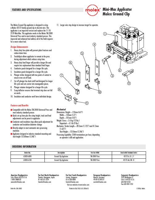
Mini-Mac Applicator Molex Ground Clipn C ompatible with the Molex TM-2000 Universal Press andmost industry standard pressesn Q uick set-up time plus the crimp height, track and feedadjustments can be preset in applicatorn C onductor and insulation rings allow quick adjustment forconductor and insulation diameter changen D irectly adapts to most automatic wire processingmachinesn A pplicator designed to industry standard mounting andshut height 135.80mm (5.346”)Mechanical Dimensions: Height—152mm (6.0”) Width—132mm (5.2”) Depth—101mm (4.0”)Weight: Gross—5.4 kg (12 lbs.) Unpacked—4.1 kb (9 lbs.)Mechanics: Stroke Length—28.5mm (1.125”) and 41.3mm (1.625”) Shut Height—135.8mm (5.346”)Processing Capability: 2500 terminations per hour, dependingon operator’s skill and application.Features and BenefitsThe Molex Ground Clip applicator is designed to crimpa Molex 42172 family ground clip to discrete wire. Thisapplicator is an improved version and replaces the 11-18-2139 Mini-Mac. This applicator works in the Molex TM-2000Universal Press and in most industry standard presses. Thisimproved and enhanced tool address all of the field requestsfor a more robust tool.Design Enhancements1. H eavy duty face plate will prevent plate fractures andreduce down time.2. T rackAdjust allows applicator to remain in the pressduring adjustment which reduces setup time.3. H eavy duty feed finger will provide a longer life andrequire less replacement than standard feed finger.4. C onductor punch designed for a longer life cycle.5. I nsulation punch designed for a longer life cycle.6. P lunger striker designed with two points of contact toensure even cut-off load.7. C ut-off plunger has dual cutoff and designed for longerlife cycle and cuts carrier into manageable pieces.8. P lunger retainer designed for a longer life cycle.9. S crap deflector ensures that terminal strip does not fallon anvils.10. I nsulation and conductor anvil have individual design.Order No.Description For Use With Used with Terminal Series 63830-6000Ground Clip Applicator TM-2000 Press 42172-A, B, C, F 63830-6100Ground Clip Applicator TM-2000 Press 42172-AA, BB. CCFEATURES AND SPECIFICATIONS Americas Headquarters Lisle, Illinois 60532 U.S.A.1-800-78MOLEX amerinfo@Far East North Headquarters Yamato, Kanagawa, Japan 81-462-65-2324feninfo@ Far East South Headquarters Jurong, Singapore 65-6-268-6868fesinfo@ European Headquarters Munich, Germany 49-89-413092-0eurinfo@ Corporate Headquarters 2222 Wellington Ct.Lisle, IL 60532 U.S.A.630-969-4550 Fax:630-969-1352Visit our website at Order No. DHL-0005 Printed in USA/100/JI/JI/2006.05 ©2006, Molex ORDERING INFORMATION元器件交易网。
General DescriptionThe MAX481, MAX483, MAX485, MAX487–MAX491, andMAX1487 are low-power transceivers for RS-485 and RS-422 communication. Each part contains one driver and onereceiver. The MAX483, MAX487, MAX488, and MAX489feature reduced slew-rate drivers that minimize E MI andreduce reflections caused by improperly terminated cables,thus allowing error-free data transmission up to 250kbps.The driver slew rates of the MAX481, MAX485, MAX490,MAX491, and MAX1487 are not limited, allowing them totransmit up to 2.5Mbps.These transceivers draw between 120µA and 500µA ofsupply current when unloaded or fully loaded with disableddrivers. Additionally, the MAX481, MAX483, and MAX487have a low-current shutdown mode in which they consumeonly 0.1µA. All parts operate from a single 5V supply.Drivers are short-circuit current limited and are protectedagainst excessive power dissipation by thermal shutdowncircuitry that places the driver outputs into a high-imped-ance state. The receiver input has a fail-safe feature thatguarantees a logic-high output if the input is open circuit.The MAX487 and MAX1487 feature quarter-unit-loadreceiver input impedance, allowing up to 128 MAX487/MAX1487 transceivers on the bus. Full-duplex communi-cations are obtained using the MAX488–MAX491, whilethe MAX481, MAX483, MAX485, MAX487, and MAX1487are designed for half-duplex applications.________________________Applications Low-Power RS-485 Transceivers Low-Power RS-422 Transceivers Level Translators Transceivers for EMI-Sensitive Applications Industrial-Control Local Area Networks__Next Generation Device Features o For Fault-Tolerant Applications MAX3430: ±80V Fault-Protected, Fail-Safe, 1/4Unit Load, +3.3V, RS-485 Transceiver MAX3440E–MAX3444E: ±15kV ESD-Protected,±60V Fault-Protected, 10Mbps, Fail-Safe, RS-485/J1708 Transceivers o For Space-Constrained Applications MAX3460–MAX3464: +5V, Fail-Safe, 20Mbps,Profibus RS-485/RS-422 Transceivers MAX3362: +3.3V, High-Speed, RS-485/RS-422Transceiver in a SOT23 Package MAX3280E–MAX3284E: ±15kV ESD-Protected,52Mbps, +3V to +5.5V, SOT23, RS-485/RS-422,True Fail-Safe Receivers MAX3293/MAX3294/MAX3295: 20Mbps, +3.3V,SOT23, RS-485/RS-422 Transmitters o For Multiple Transceiver Applications MAX3030E–MAX3033E: ±15kV ESD-Protected,+3.3V, Quad RS-422 Transmitters o For Fail-Safe Applications MAX3080–MAX3089: Fail-Safe, High-Speed (10Mbps), Slew-Rate-Limited RS-485/RS-422Transceiverso For Low-Voltage ApplicationsMAX3483E/MAX3485E/MAX3486E/MAX3488E/MAX3490E/MAX3491E: +3.3V Powered, ±15kVESD-Protected, 12Mbps, Slew-Rate-Limited,True RS-485/RS-422 Transceivers For pricing, delivery, and ordering information, please contact Maxim Direct at1-888-629-4642, or visit Maxim Integrated’s website at .______________________________________________________________Selection Table19-0122; Rev 10; 9/14PARTNUMBERHALF/FULL DUPLEX DATA RATE (Mbps) SLEW-RATE LIMITED LOW-POWER SHUTDOWN RECEIVER/DRIVER ENABLE QUIESCENT CURRENT (μA) NUMBER OF RECEIVERS ON BUS PIN COUNT MAX481Half 2.5No Yes Yes 300328MAX483Half 0.25Yes Yes Yes 120328MAX485Half 2.5No No Yes 300328MAX487Half 0.25Yes Yes Yes 1201288MAX488Full 0.25Yes No No 120328MAX489Full 0.25Yes No Yes 1203214MAX490Full 2.5No No No 300328MAX491Full 2.5No No Yes 3003214MAX1487 Half 2.5No No Yes 2301288Ordering Information appears at end of data sheet.找电子元器件上宇航军工MAX481/MAX483/MAX485/MAX487–MAX491/MAX1487Low-Power, Slew-Rate-LimitedRS-485/RS-422 TransceiversPackage Information For the latest package outline information and land patterns, go to . Note that a “+”, “#”, or “-”in the package code indicates RoHS status only. Package drawings may show a different suffix character, but the drawing pertains to the package regardless of RoHS status.16Low-Power, Slew-Rate-Limited RS-485/RS-422 TransceiversMAX481/MAX483/MAX485/MAX487–MAX491/MAX1487Maxim Integrated cannot assume responsibility for use of any circuitry other than circuitry entirely embodied in a Maxim Integrated product. No circuit patent licenses are implied. Maxim Integrated reserves the right to change the circuitry and specifications without notice at any time. The parametric values (min and max limits) shown in the Electrical Characteristics table are guaranteed. Other parametric values quoted in this data sheet are provided for guidance.Maxim Integrated 160 Rio Robles, San Jose, CA 95134 USA 1-408-601-100017©2014 Maxim Integrated Products, Inc.Maxim Integrated and the Maxim Integrated logo are trademarks of Maxim Integrated Products, Inc.。


General DescriptionDevices in the MAX3483E family (MAX3483E/MAX3485E/MAX3486E/MAX3488E/MAX3490E/MAX3491E) are ±15kV ESD-protected, +3.3V, low-power transceivers for RS-485 and RS-422 communications. Each device con-tains one driver and one receiver. The MAX3483E and MAX3488E feature slew-rate-limited drivers that minimize EMI and reduce reflections caused by improperly termi-nated cables, allowing error-free data transmission at data rates up to 250kbps. The partially slew-rate-limited MAX3486E transmits up to 2.5Mbps. The MAX3485E,MAX3490E, and MAX3491E transmit at up to 12Mbps.All devices feature enhanced electrostatic discharge (ESD) protection. All transmitter outputs and receiver inputs are protected to ±15kV using IEC 1000-4-2 Air-Gap Discharge, ±8kV using IEC 1000-4-2 Contact Discharge, and ±15kV using the Human Body Model.Drivers are short-circuit current limited and are protect-ed against excessive power dissipation by thermal shutdown circuitry that places the driver outputs into a high-impedance state. The receiver input has a fail-safe feature that guarantees a logic-high output if both inputs are open circuit.The MAX3488E, MAX3490E, and MAX3491E feature full-duplex communication, while the MAX3483E,MAX3485E, and MAX3486E are designed for half-duplex communication.ApplicationsTelecommunicationsIndustrial-Control Local Area Networks Transceivers for EMI-Sensitive Applications Integrated Services Digital Networks Packet SwitchingFeatureso ESD Protection for RS-485 I/O Pins±15kV—Human Body Model±8kV—IEC 1000-4-2, Contact Discharge ±15kV—IEC 1000-4-2, Air-Gap Discharge o Operate from a Single +3.3V Supply—No Charge Pump Required o Interoperable with +5V Logic o Guaranteed 12Mbps Data Rate (MAX3485E/MAX3490E/MAX3491E)o Slew-Rate Limited for Errorless Data Transmission (MAX3483E/MAX3488E) o 2nA Low-Current Shutdown Mode(MAX3483E/MAX3485E/MAX3486E/MAX3491E)o -7V to +12V Common-Mode Input Voltage Range o Full-Duplex and Half-Duplex Versions Available o Industry-Standard 75176 Pinout (MAX3483E/MAX3485E/MAX3486E)o Current-Limiting and Thermal Shutdown for Driver Overload ProtectionMAX3483E/MAX3485E/MAX3486E/MAX3488E/MAX3490E/MAX3491E3.3V-Powered, ±15kV ESD-Protected, 12Mbps and Slew-Rate-Limited T rue RS-485/RS-422 T ransceivers________________________________________________________________Maxim Integrated Products119-1474; Rev 0; 4/99Selector GuideOrdering InformationOrdering Information continued at end of data sheet.For free samples & the latest literature: , or phone 1-800-998-8800.For small orders, phone 1-800-835-8769.M A X 3483E /M A X 3485E /M A X 3486E /M A X 3488E /M A X 3490E /M A X 3491E3.3V-Powered, ±15kV ESD-Protected, 12Mbps and Slew-Rate-Limited T rue RS-485/RS-422 T ransceiversABSOLUTE MAXIMUM RATINGSDC ELECTRICAL CHARACTERISTICS(V = +3.3V ±0.3V, T = T to T , unless otherwise noted. Typical values are at T = +25°C.)Stresses beyond those listed under “Absolute Maximum Ratings” may cause permanent damage to the device. These are stress ratings only, and functional operation of the device at these or any other conditions beyond those indicated in the operational sections of the specifications is not implied. Exposure to absolute maximum rating conditions for extended periods may affect device reliability.Supply Voltage (V CC ).............................................................+7V Control Input Voltage (RE , DE).................................-0.3V to +7V Driver Input Voltage (DI)...........................................-0.3V to +7V Driver Output Voltage (A, B, Y, Z).......................-7.5V to +12.5V Receiver Input Voltage (A, B)..............................-7.5V to +12.5V Receiver Output Voltage (RO)....................-0.3V to (V CC + 0.3V)Continuous Power Dissipation (T A = +70°C)8-Pin SO (derate 5.88mW/°C above +70°C)..................471mW 8-Pin Plastic DIP (derate 9.09mW/°C above +70°C).....727mW14-Pin SO (derate 8.33mW/°C above +70°C)................667mW 14-Pin Plastic DIP (derate 10mW/°C above +70°C)......800mW Operating Temperature RangesMAX34_ _ EC_ _...................................................0°C to +70°C MAX34_ _ EE_ _.................................................-40°C to +85°C Storage Temperature Range.............................-65°C to +150°C Lead Temperature (soldering, 10sec).............................+300°CMAX3483E/MAX3485E/MAX3486E/MAX3488E/MAX3490E/MAX3491E3.3V-Powered, ±15kV ESD-Protected, 12Mbps and Slew-Rate-Limited T rue RS-485/RS-422 T ransceiversDC ELECTRICAL CHARACTERISTICS (continued)(V CC = +3.3V ±0.3V, T A = T MIN to T MAX , unless otherwise noted. Typical values are at T A = +25°C.)DRIVER SWITCHING CHARACTERISTICS—MAX3485E/MAX3490E/MAX3491E(V = +3.3V, T = +25°C.)DRIVER SWITCHING CHARACTERISTICS—MAX3486E(V = +3.3V, T = +25°C.)*MAX3488E and MAX3491E will be compliant to ±8kV per IEC 1000-4-2 Contact Discharge by September 1999.M A X 3483E /M A X 3485E /M A X 3486E /M A X 3488E /M A X 3490E /M A X 3491E3.3V-Powered, ±15kV ESD-Protected, 12Mbps and Slew-Rate-Limited T rue RS-485/RS-422 T ransceivers4_______________________________________________________________________________________DRIVER SWITCHING CHARACTERISTICS—MAX3483E/MAX3488E(V CC = +3.3V, T A = +25°C.)RECEIVER SWITCHING CHARACTERISTICS(V CC = +3.3V, T A = +25°C.)Note 1:∆V OD and ∆V OC are the changes in V OD and V OC , respectively, when the DI input changes state.Note 2:Measured on |t PLH (Y) - t PHL (Y)|and |t PLH (Z) - t PHL (Z)|.Note 3:The transceivers are put into shutdown by bringing RE high and DE low. If the inputs are in this state for less than 80ns, thedevices are guaranteed not to enter shutdown. If the inputs are in this state for at least 300ns, the devices are guaranteed to have entered shutdown. See Low-Power Shutdown Mode section.MAX3483E/MAX3485E/MAX3486E/MAX3488E/MAX3490E/MAX3491E3.3V-Powered, ±15kV ESD-Protected, 12Mbps and Slew-Rate-Limited T rue RS-485/RS-422 T ransceivers_______________________________________________________________________________________5Typical Operating Characteristics(V CC = +3.3V, T A = +25°C, unless otherwise noted.)252015105000.51.01.52.02.53.53.0OUTPUT CURRENT vs.RECEIVER OUTPUT LOW VOLTAGEM A X 3483E -01OUTPUT LOW VOLTAGE (V)O U T P U T C U R R E N T (m A )-20-18-16-14-12-10-8-6-4-2000.51.01.52.02.53.53.0OUTPUT CURRENT vs.RECEIVER OUTPUT HIGH VOLTAGEM A X 3483E -02OUTPUT HIGH VOLTAGE (V)O U T P U T C U R R E N T (m A )3.003.053.103.153.203.253.30-40-20020406010080RECEIVER OUTPUT HIGH VOLTAGEvs. TEMPERATURETEMPERATURE (°C)O U T P U T H I G H V O L T A G E (V )00.10.20.30.40.50.60.70.8-40-2020406010080RECEIVER OUTPUT LOW VOLTAGEvs. TEMPERATURETEMPERATURE (°C)O U T P U T L O W V O L T A G E (V )2505075100125150175024681012OUTPUT CURRENT vs.DRIVER OUTPUT LOW VOLTAGEM A X 3483E -07OUTPUT LOW VOLTAGE (V)O U T P U T C U R R E N T (m A )100908070605040302010000.5 1.0 1.5 2.0 2.5 3.53.0DRIVER OUTPUT CURRENT vs.DIFFERENTIAL OUTPUT VOLTAGEM A X 3483E -05DIFFERENTIAL OUTPUT VOLTAGE (V)O U T P U T C U R R E N T (m A )1.61.71.81.92.02.12.22.32.42.62.5-40-20020406010080DRIVER DIFFERENTIAL OUTPUT VOLTAGE vs. TEMPERATURETEMPERATURE (°C)D I F FE R E N T I A L O U T P U T V O L T A G E (V )-100-80-60-40-20543210-7-6-3-4-5-2-1OUTPUT CURRENT vs.DRIVER OUTPUT HIGH VOLTAGEM A X 3483E -08OUTPUT HIGH VOLTAGE (V)O U T P U T C U R R E N T (m A )M A X 3483E /M A X 3485E /M A X 3486E /M A X 3488E /M A X 3490E /M A X 3491E3.3V-Powered, ±15kV ESD-Protected, 12Mbps and Slew-Rate-Limited T rue RS-485/RS-422 T ransceivers0.80.70.91.01.11.2-40-2020406010080SUPPLY CURRENT vs. TEMPERATURETEMPERATURE (°C)S U P P L Y C U R R E N T (m A )Typical Operating Characteristics (continued)(V CC = +3.3V, T A = +25°C, unless otherwise noted.)0102030405060708010090-40-2020406010080SHUTDOWN CURRENT vs. TEMPERATUREM A X 3483E -10TEMPERATURE (°C)S H U T D O W N C U R R E N T (n A )Pin DescriptionMAX3483E/MAX3485E/MAX3486E/MAX3488E/MAX3490E/MAX3491E3.3V-Powered, ±15kV ESD-Protected, 12Mbps and Slew-Rate-Limited T rue RS-485/RS-422 T ransceivers_______________________________________________________________________________________7Figure 2. MAX3488E/MAX3490E Pin Configuration and Typical Operating CircuitFigure 3. MAX3491E Pin Configuration and Typical Operating CircuitFigure 1. MAX3483E/MAX3485E/MAX3486E Pin Configuration and Typical Operating CircuitM A X 3483E /M A X 3485E /M A X 3486E /M A X 3488E /M A X 3490E /M A X 3491E3.3V-Powered, ±15kV ESD-Protected, 12Mbps and Slew-Rate-Limited T rue RS-485/RS-422 T ransceivers8_______________________________________________________________________________________Figure 4. Driver V OD and V OC Figure 7. Driver Differential Output Delay and Transition TimesFigure 6. Receiver V OH and V OLFigure 5. Driver V OD with Varying Common-Mode VoltageMAX3483E/MAX3485E/MAX3486E/MAX3488E/MAX3490E/MAX3491E3.3V-Powered, ±15kV ESD-Protected, 12Mbps and Slew-Rate-Limited T rue RS-485/RS-422 T ransceivers_______________________________________________________________________________________9Figure 8. Driver Propagation TimesFigure 9. Driver Enable and Disable Times (t PZH , t PSH , t PHZ )Figure 10. Driver Enable and Disable Times (t PZL , t PSL , t PLZ )M A X 3483E /M A X 3485E /M A X 3486E /M A X 3488E /M A X 3490E /M A X 3491E3.3V-Powered, ±15kV ESD-Protected, 12Mbps and Slew-Rate-Limited T rue RS-485/RS-422 T ransceivers10______________________________________________________________________________________Figure 11. Receiver Propagation DelayFigure 12. Receiver Enable and Disable TimesNote 4: The input pulse is supplied by a generator with the following characteristics: f = 250kHz, 50% duty cycle, t r ≤6.0ns, Z O = 50Ω.Note 5: C L includes probe and stray capacitance._____________________Function TablesDevices with Receiver/Driver Enable(MAX3483E/MAX3485E/MAX3486E/MAX3491E)Table 1. Transmitting* B and A outputs are Z and Y, respectively, for full-duplex part (MAX3491E).X = Don’t care; High-Z = High impedanceTable 2. Receiving* DE is a “don’t care” (x) for the full-duplex part (MAX3491E).X = Don’t care; High-Z = High impedanceDevices without Receiver/Driver Enable(MAX3488E/MAX3490E)Table 3. TransmittingTable 4. Receiving___________Applications InformationThe MAX3483E/MAX3485E/MAX3486E/MAX3488E/MAX3490E/MAX3491E are low-power transceivers for RS-485 and RS-422 communications. The MAX3483E and MAX3488E can transmit and receive at data rates up to 250kbps, the MAX3486E at up to 2.5Mbps, and the MAX3485E/MAX3490E/MAX3491E at up to 12Mbps. The MAX3488E/MAX3490E/MAX3491E are full-duplex trans-ceivers, while the MAX3483E/MAX3485E/MAX3486E are half-duplex. Driver Enable (DE) and Receiver Enable (RE ) pins are included on the MAX3483E/MAX3485E/MAX3486E/MAX3491E. When disabled, the driver and receiver outputs are high impedance.Reduced EMI and Reflections (MAX3483E/MAX3486E/MAX3488E)The MAX3483E/MAX3488E are slew-rate limited, mini-mizing EMI and reducing reflections caused by improp-erly terminated cables. Figure 13 shows the driver output waveform of a MAX3485E/MAX3490E/MAX3491E transmitting a 125kHz signal, as well as the Fourier analysis of that waveform. High-frequency harmonics with large amplitudes are evident. Figure 14 shows the same information, but for the slew-rate-limited MAX3483E/MAX3488E transmitting the same signal. The high-frequency harmonics have much lower amplitudes,and the potential for EMI is significantly reduced.Low-Power Shutdown Mode(MAX3483E/MAX3485E/MAX3486E/MAX3491E)A low-power shutdown mode is initiated by bringing both RE high and DE low. The devices will not shut down unless both the driver and receiver are disabled (high impedance). In shutdown, the devices typically draw only 2nA of supply current.For these devices, the t PSH and t PSL enable times assume the part was in the low-power shutdown mode;the t PZH and t PZL enable times assume the receiver or driver was disabled, but the part was not shut down.MAX3483E/MAX3485E/MAX3486E/MAX3488E/MAX3490E/MAX3491E3.3V-Powered, ±15kV ESD-Protected, 12Mbps and Slew-Rate-Limited T rue RS-485/RS-422 T ransceivers______________________________________________________________________________________11INPUTS OUTPUT A, B RO ≥+0.2V 1≤-0.2V 0Inputs Open1INPUT OUTPUTS DI Z Y 101015MHz 500kHz/div 05MHz500kHz/div Figure 13. Driver Output Waveform and FFT Plot of MAX3485E/MAX3490E/MAX3491E Transmitting a 125kHz Signal Figure 14. Driver Output Waveform and FFT Plot of MAX3483E/ MAX3488E Transmitting a 125kHz SignalM A X 3483E /M A X 3485E /M A X 3486E /M A X 3488E /M A X 3490E /M A X 3491E3.3V-Powered, ±15kV ESD-Protected, 12Mbps and Slew-Rate-Limited T rue RS-485/RS-422 T ransceivers12______________________________________________________________________________________Figure 17. MAX3483E/MAX3488E Driver Propagation Delay Figure 19. MAX3483E/MAX3488E System Differential Voltage at 125kHz Driving 4000 Feet of Cable Figure 20. MAX3485E/MAX3490E/MAX3491E System Differential Voltage at 125kHz Driving 4000 Feet of CableDriver-Output Protection Excessive output current and power dissipation caused by faults or by bus contention are prevented by two mechanisms. A foldback current limit on the output stage provides immediate protection against short circuits over the whole common-mode voltage range (see Typical Operating Characteristics). In addition, a thermal shut-down circuit forces the driver outputs into a high-imped-ance state if the die temperature rises excessively.Propagation Delay Figures 15–18 show the typical propagation delays. Skew time is simply the difference between the low-to-high and high-to-low propagation delay. Small driver/receiver skew times help maintain a symmetrical mark-space ratio (50% duty cycle).The receiver skew time, |t PRLH- t PRHL|, is under 10ns (20ns for the MAX3483E/MAX3488E). The driver skew times are 8ns for the MAX3485E/MAX3490E/MAX3491E, 12ns for the MAX3486E, and typically under 50ns for the MAX3483E/MAX3488E.Line Length vs. Data Rate The RS-485/RS-422 standard covers line lengths up to 4000 feet. For line lengths greater than 4000 feet, see Figure 21 for an example of a line repeater.Figures 19 and 20 show the system differential voltage for parts driving 4000 feet of 26AWG twisted-pair wire at 125kHz into 120Ωloads.For faster data rate transmission, please consult the fac-tory.±15kV ESD Protection As with all Maxim devices, ESD-protection structures are incorporated on all pins to protect against electrostatic discharges encountered during handling and assembly. The driver outputs and receiver inputs of the MAX3483E family of devices have extra protection against static electricity. Maxim’s engineers have developed state-of-the-art structures to protect these pins against ESD of ±15kV without damage. The ESD structures withstand high ESD in all states: normal operation, shutdown, and powered down. After an ESD event, Maxim’s E versions keep working without latchup or damage.ESD protection can be tested in various ways; the transmitter outputs and receiver inputs of this product family are characterized for protection to the following limits:1)±15kV using the Human Body Model2)±8kV using the Contact-Discharge method specifiedin IEC 1000-4-23)±15kV using IEC 1000-4-2’s Air-Gap method.ESD Test Conditions ESD performance depends on a variety of conditions. Contact Maxim for a reliability report that documents test setup, test methodology, and test results.Human Body Model Figure 22a shows the Human Body Model and Figure 22b shows the current waveform it generates when dis-charged into a low impedance. This model consists of a 100pF capacitor charged to the ESD voltage of inter-est, which is then discharged into the test device through a 1.5kΩresistor.IEC 1000-4-2 The IEC 1000-4-2 standard covers ESD testing and performance of finished equipment; it does not specifi-cally refer to integrated circuits. The MAX3483E family of devices helps you design equipment that meets Level 4 (the highest level) of IEC 1000-4-2, without the need for additional ESD-protection components.The major difference between tests done using the Human Body Model and IEC 1000-4-2 is higher peak current in IEC 1000-4-2, because series resistance is lower in the IEC 1000-4-2 model. Hence, the ESD with-stand voltage measured to IEC 1000-4-2 is generally lower than that measured using the Human Body Model. Figure 23a shows the IEC 1000-4-2 model, and Figure 23b shows the current waveform for the ±8kV IEC 1000-4-2, Level 4 ESD contact-discharge test.Figure 21. Line Repeater for MAX3488E/MAX3490E/MAX3491EMAX3483E/MAX3485E/MAX3486E/MAX3488E/MAX3490E/MAX3491E3.3V-Powered, ±15kV ESD-Protected, 12Mbps and Slew-Rate-Limited T rue RS-485/RS-422 T ransceivers ______________________________________________________________________________________13M A X 3483E /M A X 3485E /M A X 3486E /M A X 3488E /M A X 3490E /M A X 3491EThe air-gap test involves approaching the device with a charged probe. The contact-discharge method connects the probe to the device before the probe is energized.Machine ModelThe Machine Model for ESD tests all pins using a 200pF storage capacitor and zero discharge resis-tance. Its objective is to emulate the stress caused when I/O pins are contacted by handling equipment during test and assembly. Of course, all pins require this protection, not just RS-485 inputs and outputs.Typical ApplicationsThe MAX3483E/MAX3485E/MAX3486E/MAX3488E/MAX3490E/MAX3491E transceivers are designed for bidirectional data communications on multipoint bus transmission lines. Figures 24 and 25 show typical net-work applications circuits. These parts can also be used as line repeaters, with cable lengths longer than 4000 feet, as shown in Figure 21.To minimize reflections, the line should be terminated at both ends in its characteristic impedance, and stub lengths off the main line should be kept as short as possible. The slew-rate-limited MAX3483E/MAX3488E and the partially slew-rate-limited MAX3486E are more tolerant of imperfect termination.3.3V-Powered, ±15kV ESD-Protected, 12Mbps and Slew-Rate-Limited T rue RS-485/RS-422 T ransceivers14______________________________________________________________________________________Figure 22a. Human Body ESD Test ModelFigure 22b. Human Body Current WaveformFigure 23a. IEC 1000-4-2 ESD Test ModelFigure 23b. IEC 1000-4-2 ESD Generator Current WaveformMAX3483E/MAX3485E/MAX3486E/MAX3488E/MAX3490E/MAX3491E3.3V-Powered, ±15kV ESD-Protected, 12Mbps and Slew-Rate-Limited T rue RS-485/RS-422 T ransceivers______________________________________________________________________________________15Figure 25. MAX3488E/MAX3490E/MAX3491E Full-Duplex RS-485 NetworkFigure 24. MAX3483E/MAX3485E/MAX3486E Typical RS-485 NetworkM A X 3483E /M A X 3485E /M A X 3486E /M A X 3488E /M A X 3490E /M A X 3491E3.3V-Powered, ±15kV ESD-Protected, 12Mbps and Slew-Rate-Limited T rue RS-485/RS-422 T ransceiversTRANSISTOR COUNT: 761Chip InformationOrdering Information (continued)Maxim cannot assume responsibility for use of any circuitry other than circuitry entirely embodied in a Maxim product. No circuit patent licenses are implied. Maxim reserves the right to change the circuitry and specifications without notice at any time.16____________________Maxim Integrated Products, 120 San Gabriel Drive, Sunnyvale, CA 94086 408-737-7600©1999 Maxim Integrated ProductsPrinted USAis a registered trademark of Maxim Integrated Products.。

General DescriptionThe MAX6375–MAX6380 are ultra-low-power circuits used for monitoring battery, power-supply, and regulat-ed system voltages. Each detector contains a precision bandgap reference, comparator, and internally trimmed resistors that set specified trip threshold voltages.These devices provide excellent circuit reliability and low cost by eliminating external components and adjustments when monitoring nominal system voltages from 2.5V to 5V.These circuits perform a single function: they assert an output signal whenever the V CC supply voltage falls below a preset threshold. The devices are differentiated by their output logic configurations and preset thresh-old voltages. The MAX6375/MAX6378 (push-pull) and MAX6377/MAX6380 (open-drain) have an active-low output (OUT is logic low when V CC is below V TH ). The MAX6376/MAX6379 have an active-high push-pull out-put (OUT is logic high when V CC is below V TH ). All parts are guaranteed to be in the correct output logic state for V CC down to 1V. The detector is designed to ignore fast transients on V CC . The MAX6375/MAX6376/MAX6377 have voltage thresholds between 2.20V and 3.08V in approximately 100mV increments. The MAX6378/MAX6379/MAX6380 have voltage thresholds between 3.30V and 4.63V in approximately 100mV increments.Ultra-low supply current of 500nA (MAX6375/MAX6376/MAX6377) makes these parts ideal for use in portable equipment. All six devices are available in a space-sav-ing SC70 package or in a tiny SOT23 package.ApplicationsPrecision Battery Monitoring Load Switching/Power SequencingPower-Supply Monitoring in Digital/Analog Systems Portable/Battery-Powered EquipmentFeatureso Ultra-Low 500nA Supply Current (MAX6375/MAX6376/MAX6377)o Thresholds Available from 2.20V to 4.63V in Approximately 100mV Incrementso ±2.5% Threshold Accuracy Over Temperature o Low Costo Available in Three Versions: Push-Pull OUT ,Push-Pull OUT, and Open-Drain OUT o Power-Supply Transient Immunity o No External Components o Available in Either a 3-Pin SC70 or 3-Pin SOT23 PackageMAX6375–MAX63803-Pin, Ultra-Low-Power SC70/SOT23Voltage Detectors________________________________________________________________Maxim Integrated Products 1Pin Configuration19-1721; Rev 2; 2/03*The MAX6375/MAX6376/MAX6377 are available in factory-pre-set thresholds from 2.20V to 3.08V, in approximately 0.1V incre-ments. The MAX6378/MAX6379/MAX6380 are available infactory-preset thresholds from 3.30V to 4.63V, in approximately 0.1V increments. Choose the desired threshold suffix fromTable 1 and insert it in the blank spaces following R.There are 21 standard versions, with a required order increment of 2500pieces. Sample stock is generally held on the standard versions only (see the Selector Guide). The required order increment is 10,000 pieces for nonstandard versions (Table 2). Contact facto-ry for availability. All devices available in tape-and-reel only.Selector Guide appears at end of data sheet.For pricing, delivery, and ordering information,please contact Maxim/Dallas Direct!at 1-888-629-4642, or visit Maxim’s website at .Ordering information continued at end of data sheetM A X 6375–M A X 63803-Pin, Ultra-Low-Power SC70/SOT23Voltage Detectors 2_______________________________________________________________________________________ABSOLUTE MAXIMUM RATINGSELECTRICAL CHARACTERISTICS(V CC = full range, T A = -40°C to +85°C, unless otherwise noted. Typical values are at T A = +25°C and V CC = 3V.) (Note 1)Stresses beyond those listed under “Absolute Maximum Ratings” may cause permanent damage to the device. These are stress ratings only, and functional operation of the device at these or any other conditions beyond those indicated in the operational sections of the specifications is not implied. Exposure to absolute maximum rating conditions for extended periods may affect device reliability.Terminal Voltage (with respect to GND)V CC ...........................................................................-0.3V to +6V OUT, OUT (push-pull)................................-0.3V to (V CC + 0.3V)OUT (open-drain).....................................................-0.3V to +6V Input Current (V CC ).............................................................20mA Output Current (OUT, OUT )................................................20mAContinuous Power Dissipation (T A = +70°C)3-Pin SC70 (derate 2.17mW/°C above +70°C)...........174mW 3-Pin SOT23 (derate 4mW/°C above +70°C)..............320mW Operating Temperature Range ...........................-40°C to +85°C Storage Temperature Range.............................-65°C to +150°C Junction Temperature......................................................+150°C Lead Temperature (soldering, 10s).................................+300°CNote 1:Production tested at +25°C only. Overtemperature limits are guaranteed by design, not production tested.MAX6375–MAX63803-Pin, Ultra-Low-Power SC70/SOT23Voltage Detectors__________________________________________Typical Operating Characteristics(V CC = 5V, T A = +25°C, unless otherwise noted.)00.30.20.10.40.50.60.70.80.91.0-40-2020406080SUPPLY CURRENT vs. TEMPERATURETEMPERATURE (°C)S U P P L Y C U R R E N T (µA )050100150200-40-2020406080PROPAGATION DELAY (FALLING)vs. TEMPERATURETEMPERATURE (°C)P R O P A G A T I O N D E L A Y (µs )040208060120100140-4020-20406080PROPAGATION DELAY (RISING)vs. TEMPERATURETEMPERATURE (°C)P R O P A G A T I O N D E L A Y (µs )50011001000MAXIMUM TRANSIENT DURATION vs. THRESHOLD OVERDRIVE100300400200THRESHOLD OVERDRIVEV TH - V CC (mV)M A X I M U M T R A N S I E N T D U R A T I O N (µs )10Pin DescriptionM A X 6375–M A X 63803-Pin, Ultra-Low-Power SC70/SOT23Voltage Detectors____________Applications InformationInterfacing to Different Logic Voltage ComponentsThe MAX6377/MAX6380 have an active-low, open-drain output. This output structure sinks current when OUT is asserted. Connect a pullup resistor from OUT to any supply voltage up to 5.50V (Figure 1). Select a resistor value large enough to allow a valid logic low (see Electrical Characteristics ), and small enough to register a logic high while supplying all input current and leakage paths connected to the OUT line.Negative-Going V CC TransientsThese devices are relatively immune to short-duration,negative-going V CC transients (glitches). The Typical Operating Characteristics show the Maximum Transient Duration vs. Threshold Overdrive graph, for which out-put pulses are not generated. The graph shows the maximum pulse width that a negative-going V CC tran-sient may typically have before the devices issue out-put signals. As the amplitude of the transient increases,the maximum-allowable pulse width decreases.Figure 1. Interfacing to Different Logic Voltage ComponentsTable 1. Factory-Trimmed Reset Thresholds ‡3-Pin, Ultra-Low-Power SC70/SOT23Voltage Detectors_______________________________________________________________________________________5Table 2. Device Marking Codes and Minimum Order IncrementsMAX6375–MAX6380M A X 6375–M A X 63803-Pin, Ultra-Low-Power SC70/SOT23Voltage Detectors 6___________________Chip InformationTRANSISTOR COUNT: 419Selector Guide**S ample stock is generally held on all standard versions.Contact factory for availability of nonstandard versions.Maxim cannot assume responsibility for use of any circuitry other than circuitry entirely embodied in a Maxim product. No circuit patent licenses are implied. Maxim reserves the right to change the circuitry and specifications without notice at any time.Maxim Integrated Products, 120 San Gabriel Drive, Sunnyvale, CA 94086 408-737-7600_____________________7©2003 Maxim Integrated ProductsPrinted USAis a registered trademark of Maxim Integrated Products.3-Pin, Ultra-Low-Power SC70/SOT23Voltage DetectorsMAX6375–MAX6380Package Information(The package drawing(s) in this data sheet may not reflect the most current specifications. For the latest package outline information,go to /packages .)。
General DescriptionThe MAX6375–MAX6380 are ultra-low-power circuits used for monitoring battery, power-supply, and regulat-ed system voltages. Each detector contains a precision bandgap reference, comparator, and internally trimmed resistors that set specified trip threshold voltages.These devices provide excellent circuit reliability and low cost by eliminating external components and adjustments when monitoring nominal system voltages from 2.5V to 5V.These circuits perform a single function: they assert an output signal whenever the V CC supply voltage falls below a preset threshold. The devices are differentiated by their output logic configurations and preset thresh-old voltages. The MAX6375/MAX6378 (push-pull) and MAX6377/MAX6380 (open-drain) have an active-low output (OUT is logic low when V CC is below V TH ). The MAX6376/MAX6379 have an active-high push-pull out-put (OUT is logic high when V CC is below V TH ). All parts are guaranteed to be in the correct output logic state for V CC down to 1V. The detector is designed to ignore fast transients on V CC . The MAX6375/MAX6376/MAX6377 have voltage thresholds between 2.20V and 3.08V in approximately 100mV increments. The MAX6378/MAX6379/MAX6380 have voltage thresholds between 3.30V and 4.63V in approximately 100mV increments.Ultra-low supply current of 500nA (MAX6375/MAX6376/MAX6377) makes these parts ideal for use in portable equipment. All six devices are available in a space-sav-ing SC70 package or in a tiny SOT23 package.ApplicationsPrecision Battery Monitoring Load Switching/Power SequencingPower-Supply Monitoring in Digital/Analog Systems Portable/Battery-Powered EquipmentFeatures♦Ultra-Low 500nA Supply Current (MAX6375/MAX6376/MAX6377)♦Thresholds Available from 2.20V to 4.63V in Approximately 100mV Increments♦±2.5% Threshold Accuracy Over Temperature ♦Low Cost♦Available in Three Versions: Push-Pull OUT ,Push-Pull OUT, and Open-Drain OUT ♦Power-Supply Transient Immunity ♦No External Components♦Available in Either a 3-Pin SC70 or 3-Pin SOT23 PackageMAX6375–MAX63803-Pin, Ultra-Low-Power SC70/SOT23Voltage Detectors________________________________________________________________Maxim Integrated Products 1Pin Configuration19-1721; Rev 3; 12/05*The MAX6375/MAX6376/MAX6377 are available in factory-presetthresholds from 2.20V to 3.08V, in approximately 0.1V increments.The MAX6378/MAX6379/MAX6380 are available in factory-preset thresholds from 3.30V to 4.63V, in approximately 0.1V increments.Choose the desired threshold suffix from Table 1 and insert it in the blank spaces following R. There are 21 standard versions,with a required order increment of 2500 pieces. Sample stock is generally held on the standard versions only (see the Selector Guide). The required order increment is 10,000 pieces for non-standard versions (Table 2). Contact factory for availability. All devices available in tape-and-reel only.Devices are available in both leaded and lead-free packaging.Specify lead-free by replacing “-T” with “+T” when ordering.Selector Guide appears at end of data sheet.For pricing, delivery, and ordering information,please contact Maxim/Dallas Direct!at 1-888-629-4642, or visit Maxim’s website at .Ordering information continued at end of data sheetM A X 6375–M A X 63803-Pin, Ultra-Low-Power SC70/SOT23Voltage Detectors 2_______________________________________________________________________________________ABSOLUTE MAXIMUM RATINGSELECTRICAL CHARACTERISTICS(V CC = full range, T A = -40°C to +85°C, unless otherwise noted. Typical values are at T A = +25°C and V CC = 3V.) (Note 1)Stresses beyond those listed under “Absolute Maximum Ratings” may cause permanent damage to the device. These are stress ratings only, and functional operation of the device at these or any other conditions beyond those indicated in the operational sections of the specifications is not implied. Exposure to absolute maximum rating conditions for extended periods may affect device reliability.Terminal Voltage (with respect to GND)V CC ...........................................................................-0.3V to +6V OUT, OUT (push-pull)................................-0.3V to (V CC + 0.3V)OUT (open-drain).....................................................-0.3V to +6V Input Current (V CC ).............................................................20mA Output Current (OUT, OUT )................................................20mAContinuous Power Dissipation (T A = +70°C)3-Pin SC70 (derate 2.17mW/°C above +70°C)...........174mW 3-Pin SOT23 (derate 4mW/°C above +70°C)..............320mW Operating Temperature Range ...........................-40°C to +85°C Storage Temperature Range.............................-65°C to +150°C Junction Temperature......................................................+150°C Lead Temperature (soldering, 10s).................................+300°CNote 1:Production tested at +25°C only. Overtemperature limits are guaranteed by design, not production tested.MAX6375–MAX63803-Pin, Ultra-Low-Power SC70/SOT23Voltage Detectors__________________________________________Typical Operating Characteristics(V CC = 5V, T A = +25°C, unless otherwise noted.)00.30.20.10.40.50.60.70.80.91.0-40-2020406080SUPPLY CURRENT vs. TEMPERATURETEMPERATURE (°C)S U P P L Y C U R R E N T (µA )050100150200-40-2020406080PROPAGATION DELAY (FALLING)vs. TEMPERATURETEMPERATURE (°C)P R O P A G A T I O N D E L A Y (µs )040208060120100140-4020-20406080PROPAGATION DELAY (RISING)vs. TEMPERATURETEMPERATURE (°C)P R O P A G A T I O N D E L A Y (µs )50011001000MAXIMUM TRANSIENT DURATION vs. THRESHOLD OVERDRIVE100300400200THRESHOLD OVERDRIVEV TH - V CC (mV)M A X I M U M T R A N S I E N T D U R A T I O N (µs )10Pin DescriptionM A X 6375–M A X 63803-Pin, Ultra-Low-Power SC70/SOT23Voltage Detectors____________Applications InformationInterfacing to Different Logic Voltage ComponentsThe MAX6377/MAX6380 have an active-low, open-drain output. This output structure sinks current when OUT is asserted. Connect a pullup resistor from OUT to any supply voltage up to 5.50V (Figure 1). Select a resistor value large enough to allow a valid logic low (see Electrical Characteristics ), and small enough to register a logic high while supplying all input current and leakage paths connected to the OUT line.Negative-Going V CC TransientsThese devices are relatively immune to short-duration,negative-going V CC transients (glitches). The Typical Operating Characteristics show the Maximum Transient Duration vs. Threshold Overdrive graph, for which out-put pulses are not generated. The graph shows the maximum pulse width that a negative-going V CC tran-sient may typically have before the devices issue out-put signals. As the amplitude of the transient increases,the maximum-allowable pulse width decreases.Figure 1. Interfacing to Different Logic Voltage ComponentsTable 1. Factory-Trimmed Reset Thresholds ‡3-Pin, Ultra-Low-Power SC70/SOT23Voltage Detectors_______________________________________________________________________________________5Table 2. Device Marking Codes and Minimum Order IncrementsMAX6375–MAX6380M A X 6375–M A X 63803-Pin, Ultra-Low-Power SC70/SOT23Voltage Detectors 6__________________________________________________________________________________________________________Chip InformationTRANSISTOR COUNT: 419Selector Guide**Sample stock is generally held on all standard versions.Contact factory for availability of nonstandard versions.*The MAX6375/MAX6376/MAX6377 are available in factory-presetthresholds from 2.20V to 3.08V, in approximately 0.1V increments.The MAX6378/MAX6379/MAX6380 are available in factory-preset thresholds from 3.30V to 4.63V, in approximately 0.1V increments.Choose the desired threshold suffix from Table 1 and insert it in the blank spaces following R. There are 21 standard versions,with a required order increment of 2500 pieces. Sample stock is generally held on the standard versions only (see the Selector Guide). The required order increment is 10,000 pieces for non-standard versions (Table 2). Contact factory for availability. All devices available in tape-and-reel only.Devices are available in both leaded and lead-free packaging.Specify lead-free by replacing “-T” with “+T” when ordering.Maxim cannot assume responsibility for use of any circuitry other than circuitry entirely embodied in a Maxim product. No circuit patent licenses are implied. Maxim reserves the right to change the circuitry and specifications without notice at any time.Maxim Integrated Products, 120 San Gabriel Drive, Sunnyvale, CA 94086 408-737-7600_____________________7©2005 Maxim Integrated ProductsPrinted USAis a registered trademark of Maxim Integrated Products, Inc.3-Pin, Ultra-Low-Power SC70/SOT23Voltage DetectorsMAX6375–MAX6380Package Information(The package drawing(s) in this data sheet may not reflect the most current specifications. For the latest package outline information,go to /packages .)。