LC6311(+)UART+USB多EP业务流程手册
- 格式:pdf
- 大小:644.14 KB
- 文档页数:43
UART原理及接收模块设计原理UART(Universal Asynchronous Receiver/Transmitter)是一种串行通信接口,用于在计算机系统之间传输数据。
它是一种基本的通信模式,常用于嵌入式系统和电子设备之间的数据交换。
UART的工作原理是通过串行传输数据。
它使用两根线来完成数据传输,一根线用于数据的传输,称为TX(Transmit),另一根线用于接收数据,称为RX(Receive)。
数据传输的时钟信号由发送端提供,并且在发送和接收过程中必须是同步的。
UART的传输方式分为同步传输和异步传输。
同步传输需要让发送端和接收端之间保持恒定的时钟信号进行数据同步,而异步传输则是通过在数据中添加起始位和停止位来进行同步。
由于异步传输不需要精密的时钟同步,因此更加简单和常用。
在UART中,数据传输的过程可以分为以下几个步骤:1.起始位:发送端在每个数据传输周期开始时发送一个低电平信号作为起始位。
接收端在接收到低电平信号时开始接收数据。
2.数据位:发送端在起始位之后按照事先约定好的数据格式(通常为8位数据长度)发送数据。
3.停止位:发送端在数据位之后发送一个高电平信号作为停止位。
接收端通过检测到停止位来确认数据传输的结束。
4.数据接收:接收端通过读取RX线上的电平信号来接收数据。
接收端在每个数据位的中间时刻进行采样,以确保准确读取数据。
接收模块是UART通信的重要组成部分,它的设计原理如下:1.引脚配置:接收模块需要将RX引脚与传输数据的设备连接。
在连接之前,需要配置引脚的工作模式为UART模式。
2.中断处理:接收模块可以通过中断来实现数据的接收。
当接收端检测到起始位时,会触发中断,并将接收到的数据存储到接收缓冲区中。
3.数据存储:接收模块需要定义一个接收缓冲区来存储接收到的数据。
通过中断将接收到的数据写入缓冲区,并设置一个标志位来表示有新的数据被接收到。
4.数据处理:接收模块可以通过轮询或状态机的方式来处理接收到的数据。

CBZ-6300系列微机线路保护测控装置技术说明书(V2.11)上海继电器有限公司 Shanghai Relay Co.,Ltd目 录1 概述 (1)1.1 适用范围 (1)1.2 基本配置 (1)1.3 CBZ-6300系列线路保护装置功能一览表 (3)2 技术参数 (5)3装置的工作原理 (6)3.1 三段定时限过流保护(可带方向、低电压闭锁) (6)3.1.1方向元件 (7)3.1.2低压元件 (7)3.1.3三段定时限过流保护(可带方向、低电压闭锁) (8)3.2三相二次重合闸(检无压、检同期) (8)3.3后加速电流保护(可带方向、低电压闭锁) (11)3.4充电保护 (12)3.5反时限电流保护 (12)3.6三段定时限零序过流保护(可带方向、零序电压闭锁) (13)3.6.1零序方向元件 (13)3.6.2零序电压元件 (14)3.6.3三段定时限零序过流保护(可带方向、零序电压闭锁) (14)3.7 低压侧零序过流保护 (14)3.8 过负荷保护 (15)3.9低频减载 (15)3.10低压减载 (15)3.11小电流接地选线 (16)3.12失压保护 (17)3.13 PT、CT断线告警 (17)3.13.1 母线PT断线告警 (17)3.13.2 线路PT断线告警 (18)3.13.3 CT断线告警 (18)3.14辅助功能 (19)3.14.1装置自检功能 (19)3.14.2控制回路断线监测 (19)3.14.3弹簧未储能监测 (19)4装置定值整定及接线原理图、端子图 (20)4.1装置的安装开孔图 (20)4.2 CBZ-6311线路保护及测控装置 (20)4.2.1装置背板端子图及原理接线图 (20)4.2.2定值清单 (23)4.3 CBZ-6312线路保护及测控装置 (25)I4.3.1装置背板端子图及原理接线图 (25)4.3.2定值清单 (28)4.4 CBZ-6315线路保护及测控装置 (30)4.4.1装置背板端子图及原理接线图 (30)4.4.2定值清单 (33)4.5 CBZ-6316线路保护及测控装置 (34)4.5.1装置背板端子图及原理接线图 (34)4.5.2定值清单 (36)4.6 CBZ-6313线路保护及测控装置 (38)4.6.1装置背板端子图及原理接线图 (38)4.6.2定值清单 (42)5 整定说明 (44)6调试大纲 (46)6.1调试注意事项 (46)6.2装置通电前检查 (47)6.3绝缘检查 (47)6.4上电检查 (47)6.5采样精度检查 (47)6.6开关量输入检查 (47)6.7继电器接点校验 (47)6.8定值校验 (47)6.9跳合闸电流保持试验 (47)7订货须知 (47)CBZ-6300系列线路保护测控装置1 概述1.1 适用范围CBZ-6300系列线路保护及测控装置包括CBZ-6311、CBZ-6312、CBZ-6315、CBZ-6316等装置,可满足35kV及以下电压等级各设备的保护和监控需求,为35kV及以下电压等级小型变电站、10kV开闭所、办公设施等电力客户提供最优性能价格比的成套保护测控装置。
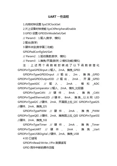
UART一些流程1.内核时钟设置SysCtlClockSet2.片上设备时钟使能SysCtlPeripheralEnable3.GPIO设置GPIODirModeSet/Get// Param3:1.输入(数字、模拟)2.输出(数字)3.硬件决定(数字第二功能)GPIOPadConfigSet/Get// Param2:1.驱动强度(数字、模拟)// Param3:1.推挽/开漏(数字) 2.模拟功能(模拟)注:上述两个函数被封装成了以下函数做简化GPIOPinTypeGPIOInput //输入、2mA、推挽_GPIOGPIOPinTypeGPIOOnput //输出、2m、推挽_GPIO GPIOPinTypeGPIOOutputOD //输出、2mA、开漏_GPIO GPIOPinTypeADC //输入、2mA、模拟_ADC GPIOPinTypeComparator //输入、2mA、模拟_比较器GPIOPinTypeCAN //硬件、8mA、推挽_CAN GPIOPinTypeEthernetLED //硬件、8mA、推挽_以太网LED GPIOPinTypeI2C //硬件、2mA、开漏弱上拉_I2C GPIOPinTypeI2S //硬件、2mA、推挽_I2SGPIOPinTypePWM //硬件、2mA、推挽_PWM GPIOPinTypeQEI //硬件、2mA、推挽弱上拉_QEI GPIOPinTypeSSI //硬件、2mA、推挽_SSIGPIOPinTypeTimer //硬件、2mA、推挽_Timer GPIOPinTypeUART //硬件、2mA、推挽_Uart GPIOPinTypeUSBDigital //硬件、2mA、推挽_USB4 IO口读写GPIOPinRead/Write //Pin数据读写GPIO用作中断的操作流程1.系统时钟配置SysCtlClockSet2.GPIO设备时钟打开SysCtlPeripheralEnable3.Pin脚功能设置GPIOPinTypeInput4.Pin脚中断触发模式设置GPIOIntTypeSet //0.片内外设中断模式配置5.Pin脚中断允许GPIOPinIntEnable //1.使能片内外设的具体中断6.内设中断允许IntEnable //2.使能片内外设的总中断7.MCU总中断允许IntMasterEnable //3.使能MCU的总中断中断服务程序1.读取中断源GPIOPinIntStatus2.清除中断源GPIOPinIntClear //M3的内核中断,不需要手动清除UART的操作流程1.系统时钟配置SysCtlClockSet2.GPIO设备时钟打开SysCtlPeripheralEnable3.UART设备时钟打开SysCtlPeripheralEnable4.GPIO复用引脚设定为Tx和Rx GPIOPinTypeUART5.1UART工作参数配置UARTConfigSetExpClk[5.2] 若使用UART中断模式,则需配置5.2.1 Tx和Rx引脚中断允许UARTIntEnable5.2.2 UART功能启动UARTEnable5.2.3 内设中断允许IntEnable6.UART收发6.1 Block模式:(将NoBlock模式的4个函数封装成2个)直接发送字符UARTCharPut直接接收字符UARTCharGet6.2 NoBlock模式:(使用FIFO)等待Rx_FIFO有数据UARTCharsAvail等待Tx_FIFO有数据UARTSpaceAvailBlock发送字符UARTCharPutNonBlockingBlock接收字符UARTCharGetNonBlocking (注:使用此函数,必须先查询UARTCharsAvail)6.3 INT模式:(中断服务函数)UART中断清除UARTIntClear使用Block/NoBlock模式发送和接收字符PWM的操作流程1.系统时钟设置SysCtlClockSet2.PWM模块时钟设置SysCtlPWMClockSet3.GPIO设备时钟打开SysCtlPeripheralEnable4.PWM模块时钟打开SysCtlPeripheralEnable5.GPIO设置为硬件指定(PWM) GPIOPinTypePWM6.Pin脚配置为PWM功能GPIOPinConfigure7.PWM发生器计数模式设置PWMGenConfigure8.PWM发生器周期设置PWMGenPeriodSet9.PWM发生器脉宽设置PWMPulseWidthSet10.PWM输出管脚使能PWMOutputState10111.PWM启动PWMGenEnable102 103 104 105SysTick的操作流程1.系统时钟设置SysCtlClockSet2.SysTick周期设置SysTickPeriodSet//减法计数器,归零后自动重装3.SysTick启动SysTickEnable1114.MCU总中断开启IntMasterEnable5.SysTick中断服务函数void SysTick_ISR() { //SysTick是系统内设,硬件自动清除中断,无须手动清除Timer的操作流程32bit 定时器32bit RTC定时器16bit 定时器16bit 捕获器(边沿计数:计算有几个边沿;边沿定时:计算前后边沿的时间差)16bit PWM1.系统时钟设置SysCtlClockSet2.片上设备时钟使能SysCtlPeripheralEnable3.定时器工作模式设置TimerConfigure4.定时器载入值设置TimerLoadSet5.定时器中断使能TimerIntEnable1366.外设中断总使能IntEnable7.MCU总中断使能IntMaskEnable8.定时器启动TimerEnable140Timer中断服务函数void Timer_ISR() { //手工清除中断状态TimerIntClear(); ...//功能代码}ADC操作流程1.系统时钟设置SysCtlClockSet2.ADC所在GPIO外设时钟打开SysCtlPeripheralEnable(SYSCTL_PERIPH_GPIOE);3.IO口配置为ADC功能GPIOPinTypeADC(GPIO_PORTE_BASE, GPIO_PIN_3);4.ADC外设时钟打开SysCtlPeripheralEnable(SYSCTL_PERIPH_ADC);5.ADC采样序列配置ADCSequenceConfigure(ADC0_BASE, 3, DC_TRIGGER_PROCESSOR, 0);6.ADC采样序列步进配置ADCSequenceStepConfigure(ADC0_BASE, 3, 0, ADC_CTL_CH0 | ADC_CTL_IE | ADC_CTL_END); // 启动AD的采样序列发生器3 ADCSequenceEnable(ADC0_BASE, 3); // 清除中断标志ADCIntClear(ADC0_BASE, 3);。
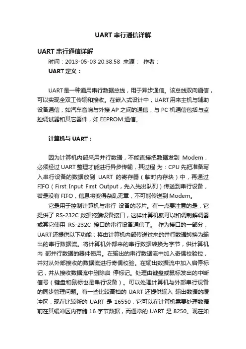
UART串行通信详解UART串行通信详解时间:2013-05-03 20:38:58 来源:作者:UART定义:UART是一种通用串行数据总线,用于异步通信。
该总线双向通信,可以实现全双工传输和接收。
在嵌入式设计中,UART用来主机与辅助设备通信,如汽车音响与外接AP之间的通信,与PC机通信包括与监控调试器和其它器件,如EEPROM通信。
计算机与UART:因为计算机内部采用并行数据,不能直接把数据发到Modem,必须经过UART整理才能进行异步传输,其过程为:CPU先把准备写入串行设备的数据放到UART的寄存器(临时内存块)中,再通过FIFO(First Input First Output,先入先出队列)传送到串行设备,若是没有FIFO,信息将变得杂乱无章,不可能传送到Modem。
它是用于控制计算机与串行设备的芯片。
有一点要注意的是,它提供了RS-232C数据终端设备接口,这样计算机就可以和调制解调器或其它使用RS-232C接口的串行设备通信了。
作为接口的一部分,UART还提供以下功能:将由计算机内部传送过来的并行数据转换为输出的串行数据流。
将计算机外部来的串行数据转换为字节,供计算机内部并行数据的器件使用。
在输出的串行数据流中加入奇偶校验位,并对从外部接收的数据流进行奇偶校验。
在输出数据流中加入启停标记,并从接收数据流中删除启停标记。
处理由键盘或鼠标发出的中断信号(键盘和鼠标也是串行设备)。
可以处理计算机与外部串行设备的同步管理问题。
有一些比较高档的UART还提供输入输出数据的缓冲区,现在比较新的UART是16550,它可以在计算机需要处理数据前在其缓冲区内存储16字节数据,而通常的UART是8250。
现在如果您购买一个内置的调制解调器,此调制解调器内部通常就会有16550 UART。
UART是计算机中串行通信端口的关键部分。
在计算机中,UART 相连于产生兼容RS232规范信号的电路。
RS232标准定义逻辑“1”信号相对于地为-3到-15伏,而逻辑“0”相对于地为+3到+15伏。
汇编:审核:批准:文件编号:LJ/QMS-I630 版 本:第A 版 受控状态: 分 发 号: 持 有 人:2010-08-01发布 2010-08-01实施重庆龙驹汽车配件有限公司 发布切割机操作规程1、适用范围:1-1电源:380V Ac。
1-2适用砂轮:ф205(230)*1.2t*ф25.4(内孔)·ф31.75(内孔)1-3切割能力:圆棒maxф32,管ф50,方体20t*60lmm2、操作说明:2-1安装砂轮片和工作物体于固定台上。
2-2扳动照明灯开关,打开照明灯。
2-3将喷水管推向砂轮片前方;切割时冷却水可直接喷淋砂轮片及工作物件。
2-4拉下机体上盖。
2-5左转推送手轮把工作物件推进砂轮片边缘微微接触。
2-6扭动切割开关也同时扭动水泵开关启动马达水泵,待马达转动安定后,握住推送手轮向左转动,将夹具组缓缓推送进行切割。
2-7切割完毕将推送手轮向右转动退回夹具组。
2-8打开机体上盖,稍稍放松夹具杆再推高半屏牙螺牙,向左旋动夹具螺杆拉出活动块,即可取出工作物件。
3、保养及注意事项:3-1推送研削速度不可行进太快,否则研削面会粗糙,速度快慢可视工作物件的软硬、大小而定,行进中若发生震动表示推送太快,应减缓推送速度以免砂轮破裂。
3-2注意切削时冷却水流动情形,细小或无水时应察看是否水管堵塞或冷却水箱内无水,冷却水箱内残渣应经常清理并加水以保持冷却水清洁并可预防水管堵塞。
3-3每日作业完应清理内部并擦干净主轴为使冷却良好未上漆,请注意保养。
3-4主轴若发生振动声音可能是轴承故障,轴承采用605522*6个。
3-5工作物件切勿撞及砂轮固定法兰。
铣床操作规程1、适用范围:公司内铣床。
2、操作说明:2-1操作前准备:2-1-1电源总开关是否开启。
2-1-2工作物是否夹紧。
2-1-3车轨润滑油是否满足要求。
2-2操作步骤:2-2-1将“绿色”起动按钮按下,使主轴运转。
2-2-2按下“红色”按钮,主轴停止。

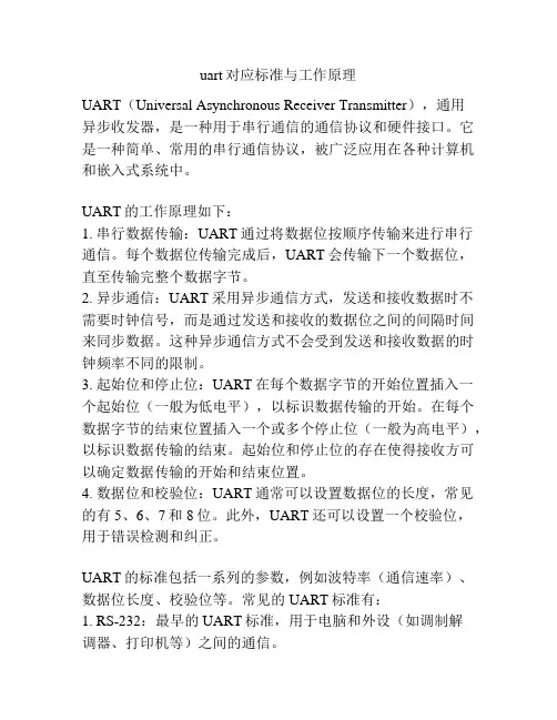
uart对应标准与工作原理UART(Universal Asynchronous Receiver Transmitter),通用异步收发器,是一种用于串行通信的通信协议和硬件接口。
它是一种简单、常用的串行通信协议,被广泛应用在各种计算机和嵌入式系统中。
UART的工作原理如下:1. 串行数据传输:UART通过将数据位按顺序传输来进行串行通信。
每个数据位传输完成后,UART会传输下一个数据位,直至传输完整个数据字节。
2. 异步通信:UART采用异步通信方式,发送和接收数据时不需要时钟信号,而是通过发送和接收的数据位之间的间隔时间来同步数据。
这种异步通信方式不会受到发送和接收数据的时钟频率不同的限制。
3. 起始位和停止位:UART在每个数据字节的开始位置插入一个起始位(一般为低电平),以标识数据传输的开始。
在每个数据字节的结束位置插入一个或多个停止位(一般为高电平),以标识数据传输的结束。
起始位和停止位的存在使得接收方可以确定数据传输的开始和结束位置。
4. 数据位和校验位:UART通常可以设置数据位的长度,常见的有5、6、7和8位。
此外,UART还可以设置一个校验位,用于错误检测和纠正。
UART的标准包括一系列的参数,例如波特率(通信速率)、数据位长度、校验位等。
常见的UART标准有:1. RS-232:最早的UART标准,用于电脑和外设(如调制解调器、打印机等)之间的通信。
2. RS-422:一种差分信号的串行通信标准,适用于长距离和高速通信。
3. RS-485:多点通信的标准,适用于多个设备之间的通信。
总的来说,UART是一种简单易用、广泛应用的串行通信协议和硬件接口,通过起始位、停止位和异步通信方式实现数据的传输和同步,适用于各种计算机和嵌入式系统中的串行通信需求。
1.内核时钟设置SysCtlClockSet2.片上设备时钟使能SysCtlPeripheralEnable3.GPIO设置GPIODirModeSet/Get// Param3:1.输入(数字、模拟)2.输出(数字)3.硬件决定(数字第二功能)GPIOPadConfigSet/Get// Param2:1.驱动强度(数字、模拟)// Param3:1.推挽/开漏(数字) 2.模拟功能(模拟)注:上述两个函数被封装成了以下函数做简化GPIOPinTypeGPIOInput //输入、2mA、推挽_GPIOGPIOPinTypeGPIOOnput //输出、2m、推挽_GPIO GPIOPinTypeGPIOOutputOD //输出、2mA、开漏_GPIO GPIOPinTypeADC //输入、2mA、模拟_ADC GPIOPinTypeComparator //输入、2mA、模拟_比较器GPIOPinTypeCAN //硬件、8mA、推挽_CAN GPIOPinTypeEthernetLED //硬件、8mA、推挽_以太网LED GPIOPinTypeI2C //硬件、2mA、开漏弱上拉_I2C GPIOPinTypeI2S //硬件、2mA、推挽_I2SGPIOPinTypePWM //硬件、2mA、推挽_PWM GPIOPinTypeQEI //硬件、2mA、推挽弱上拉_QEI GPIOPinTypeSSI //硬件、2mA、推挽_SSIGPIOPinTypeTimer //硬件、2mA、推挽_Timer GPIOPinTypeUART //硬件、2mA、推挽_Uart GPIOPinTypeUSBDigital //硬件、2mA、推挽_USB4 IO口读写GPIOPinRead/Write //Pin数据读写GPIO用作中断的操作流程1.系统时钟配置SysCtlClockSet2.GPIO设备时钟打开SysCtlPeripheralEnable3.Pin脚功能设置GPIOPinTypeInput4.Pin脚中断触发模式设置GPIOIntTypeSet //0.片内外设中断模式配置5.Pin脚中断允许GPIOPinIntEnable //1.使能片内外设的具体中断6.内设中断允许IntEnable //2.使能片内外设的总中断7.MCU总中断允许IntMasterEnable //3.使能MCU的总中断中断服务程序1.读取中断源GPIOPinIntStatus2.清除中断源GPIOPinIntClear //M3的内核中断,不需要手动清除UART的操作流程1.系统时钟配置SysCtlClockSet2.GPIO设备时钟打开SysCtlPeripheralEnable3.UART设备时钟打开SysCtlPeripheralEnable4.GPIO复用引脚设定为Tx和Rx GPIOPinTypeUART5.1UART工作参数配置UARTConfigSetExpClk[5.2] 若使用UART中断模式,则需配置5.2.1 Tx和Rx引脚中断允许UARTIntEnable5.2.2 UART功能启动UARTEnable5.2.3 内设中断允许IntEnable6.UART收发6.1 Block模式:(将NoBlock模式的4个函数封装成2个)直接发送字符UARTCharPut直接接收字符UARTCharGet6.2 NoBlock模式:(使用FIFO)等待Rx_FIFO有数据UARTCharsAvail等待Tx_FIFO有数据UARTSpaceAvailBlock发送字符UARTCharPutNonBlockingBlock接收字符UARTCharGetNonBlocking (注:使用此函数,必须先查询UARTCharsAvail)6.3 INT模式:(中断服务函数)UART中断清除UARTIntClear使用Block/NoBlock模式发送和接收字符PWM的操作流程1.系统时钟设置SysCtlClockSet2.PWM模块时钟设置SysCtlPWMClockSet3.GPIO设备时钟打开SysCtlPeripheralEnable4.PWM模块时钟打开SysCtlPeripheralEnable5.GPIO设置为硬件指定(PWM) GPIOPinTypePWM6.Pin脚配置为PWM功能GPIOPinConfigure7.PWM发生器计数模式设置PWMGenConfigure8.PWM发生器周期设置PWMGenPeriodSet9.PWM发生器脉宽设置PWMPulseWidthSet10.PWM输出管脚使能PWMOutputState10111.PWM启动PWMGenEnable102 103 104 105SysTick的操作流程1.系统时钟设置SysCtlClockSet2.SysTick周期设置SysTickPeriodSet//减法计数器,归零后自动重装3.SysTick启动SysTickEnable1114.MCU总中断开启IntMasterEnable5.SysTick中断服务函数void SysTick_ISR() { //SysTick是系统内设,硬件自动清除中断,无须手动清除Timer的操作流程32bit 定时器32bit RTC定时器16bit 定时器16bit 捕获器(边沿计数:计算有几个边沿;边沿定时:计算前后边沿的时间差)16bit PWM1.系统时钟设置SysCtlClockSet2.片上设备时钟使能SysCtlPeripheralEnable3.定时器工作模式设置TimerConfigure4.定时器载入值设置TimerLoadSet5.定时器中断使能TimerIntEnable1366.外设中断总使能IntEnable7.MCU总中断使能IntMaskEnable8.定时器启动TimerEnable140Timer中断服务函数void Timer_ISR() { //手工清除中断状态TimerIntClear(); ...//功能代码}ADC操作流程1.系统时钟设置SysCtlClockSet2.ADC所在GPIO外设时钟打开SysCtlPeripheralEnable(SYSCTL_PERIPH_GPIOE);3.IO口配置为ADC功能GPIOPinTypeADC(GPIO_PORTE_BASE, GPIO_PIN_3);4.ADC外设时钟打开SysCtlPeripheralEnable(SYSCTL_PERIPH_ADC);5.ADC采样序列配置ADCSequenceConfigure(ADC0_BASE, 3, DC_TRIGGER_PROCESSOR, 0);6.ADC采样序列步进配置ADCSequenceStepConfigure(ADC0_BASE, 3, 0, ADC_CTL_CH0 | ADC_CTL_IE | ADC_CTL_END); // 启动AD的采样序列发生器3 ADCSequenceEnable(ADC0_BASE, 3); // 清除中断标志ADCIntClear(ADC0_BASE, 3);。
USB CPI CLIP User ManualHA031522/1May 2013© 2013 Eurotherm LimitedAll rights are strictly reserved. No part of this document may be reproduced, modified, or transmitted in any form by any means, nor may it be stored in a retrieval system other than for the purpose to act as an aid in operating the equipment to which the document relates, without the prior, written permission of Eurotherm Limited.- - - - - - - - - - - - -Eurotherm Limited pursues a policy of continuous development and product improvement. The specification in this document may therefore be changed without notice. The information in this document is given in good faith, but is intended for guidance only. Eurotherm Limited will accept no responsibility for any losses arising from errors in this document.USB CPI Clip User ManualUSB CPI ClipUser Manual Part Number HA031522 Issue 1 May -2013Contents 1.DESCRIPTION (2)1.1Hardware Features (2)1.2Installation (3)1.3Virtual Comm Port (VCP) Driver (3)2.VCP DRIVER INSTALLATION UNDER WINDOWS XP (4)2.1To install the VCP driver under Windows XP (4)2.2To View the Ports Allocated (6)3.VCP DRIVER INSTALLATION UNDER WINDOWS 7 X32/X64 (7)4.UNINSTALLING VCP DRIVERS (8)ING THE USB CLIP TO CONFIGURE AN INSTRUMENT (9)ING THE USB CLIP TO UPGRADE AN INSTRUMENT (10)6.1To Install the Upgrade Software (10)6.2Launch the Upgrade (12)7.CERTIFICATIONS, ENVIRONMENTAL AND SAFETY (13)Part No HA031522 Issue 1.0 May -13 CN29289 1USB CPI Clip User ManualPart No HA031522 Issue 1.0 May -13 2 1. DescriptionThe CPI clip allows configuration and back up of Eurotherm 3000, piccolo and nanodac series of panel mounted instruments and mini8 rack mounted controller. It supplies power to the instrument derived from the USB port of the host computer so that it can be used without the need for a power connection.external power.than that provided by the USB port.1.1 Hardware FeaturesUsb ConnectionPin FunctionsFunction 1 Vbus Power2 D- Data -3 D+ Data +4 Gnd GroundInstrument connectionThe cable connects to the instrument by a 5 pin configuration clip with a custom plastic insert and a shell. The pin description is shown below,1. instrument.2. from product micro)3. UART receive)4. Ground power connection.5. Provides +5V power to theinstrument.USB CPI Clip User Manual Part No HA031522 Issue 1.0 May -13 3 1.2 InstallationWith reference to the picture:1. The connector can be inserted independently of the device being fitted into its sleeve or not.2. If the controller/indicator is fitted in a panel, remove it and position it on the bench.3. Connect the 5-pin connector to the socket on the side of the device. Push the connector in to the stop.4. Connect the USB connector to the pc which is to be used to install the program.5. After programming one device it is enough to remove the 5-pin connector and insert it directly into theside of a further device and download the configuration data.1.3 Virtual Comm Port (VCP) DriverThe VCP driver emulates a standard PC serial port such that communications can be made with the USB device as a standard RS232 port. Before the CPI clip can be used, therefore, it is necessary to download the VCP driver. If the operating system on the PC is Windows7 the driver should be recognised when the clip is first connected. In this case it should not be necessary to take any further action.If the driver is not installed automatically or if the operating system is XP, for example, it is necessary to install the driver manually, see following sections. The driver can be found on the iTools CD or it can be downloaded from /usbcpi .During the installation the port is allocated a port number. Toinspect the port number after installation go to Ports in the DeviceManager, for example, Control Panel t System t Hardware tDevice Manager t Ports.It is possible to re-number the port - double click on ‘USB Serial Port(COMX)’ to open its properties. In Port Settings t Advanced, theport number can be changed using the drop down box. This mayonly be required in the unlikely event that a port number greaterthan 16 has been allocated since iTools defaults to 16 ports.Although it is possible to increase this to 32 in iTools the scan willbecome slow. It is, therefore, not recommended to make thischange.USB CPI Clip User ManualPart No HA031522 Issue 1.0 May -13 4 2. VCP Driver Installation under Windows XPIf a device of the same type has been installed on your machine before, and the drivers that are about to be installed are different from those installed already, the original drivers need to be uninstalled. Please refer to the Uninstalling VCP Drivers section of this document for further details of this procedure.2.1 To install the VCP driver under Windows XPDownload the latest available VCP drivers from the iTools CD or from /usbcpi . and unzip them to a location on your PC.• Connect the device to a spare USB port on your PC. Windows FoundNew Hardware Wizard will launch andthe screen shown in Figure 2-1 isdisplayed. Select "No, not this time"from the options available and thenclick "Next" to proceed with theinstallation.Figure 2-1• Select "Install from a list or specific location (Advanced)" as shown inFigure 2-2 and then click "Next".Figure 2-2USB CPI Clip User Manual Part No HA031522 Issue 1.0 May -13 5 • Select "Search for the best driver in these locations" and enter the filepath in the combo-box (for example,"C:\CDM 2.02.04" in Figure 2-3) orbrowse to it by clicking the browsebutton. Once the file path has beenentered in the box, click next toproceed.Figure 2-3• If Windows XP is configured to warn when unsigned (non-WHQL certified) drivers are about to beinstalled, the message dialogue shown in Figure 2-4will be displayed. Click on "Continue Anyway" tocontinue with the installation. If Windows XP isconfigured to ignore file signature warnings, nomessage will appear.Figure 2-4• The screen shown in Figure 2-5 will be displayed as Windows XP copies therequired driver files.Figure 2-5USB CPI Clip User Manual Part No HA031522 Issue 1.0 May -13 6 • Windows should then display a message indicating that theinstallation was successful (Figure2-6). Click "Finish" to complete theinstallation for the first port of thedevice.Figure 2-6If the device is based on the FT2232, the Found New Hardware Wizard will continue by installing the USB Serial Converter driver for the second port of the FT2232 device. The procedure for installing the second port is identical to that for installing the first port from the first screen of the Found New Hardware Wizard.2.2 To View the Ports Allocated• Open the Device Manager (located in "Control Panel\System" then selectthe "Hardware" tab and click "DeviceManger") and select "View > Devicesby Connection". The device appearsas a "USB Serial Converter" with anadditional COM port with the label"USB Serial Port" (Figure 2-7). If thedevice is based on the FT2232, twoports will be available from acomposite USB device.Figure 2-7• In the case of the FT2232, port A of the FT2232 will be installed as COMXand port B will be installed asCOMX+1 where COMX is the firstavailable COM port number.Figure 2-8USB CPI Clip User Manual Part No HA031522 Issue 1.0 May -13 7 3. VCP Driver Installation under Windows 7 x32/x64Connect the device to a spare USB port on your PC.With Windows 7, drivers should be installed automatically.If no suitable driver is automatically found then the following procedure should be followed.•In the Hardware tab select Device Manager.• In the Device Manager window there will be a device under Other Devices with a yellowwarning symbol to indicate a problem, i.e. nodriver installed. The text next to this devicewill depend on the device attached. In thisexample the device was a TTL232R device.• Right click on the other device (TTL232R in this example) to bring up a menu as shownbelow.• From the displayed menu select ‘Update Driver Software’.• This will launch the ‘Welcome to the Found New Hardware Wizard’ shown in section 2.1.•Repeat the procedure in section 2.1 to install the driver.• Press the Windows ‘Start’ button to bring up the start menu and select “Control Panel”. • From the Control Panel window select SystemUSB CPI Clip User ManualPart No HA031522 Issue 1.0 May -13 8 4. Uninstalling VCP DriversDevices can be removed using the Device Manager by simply right-clicking on the device and selecting "Uninstall". This will delete the associated registry entries for that device only.Under Windows XP, driver files and OEM INF and PNF files must be removed manually or by using a custom application. OEM INF and PNF files are located in the Windows\Inf directory and can be identified by searching for a VID and PID string matching the device installed e.g. VID_0403&PID_6001. Once the matching OEM INF files are found (e.g. oem10.inf for FTDIBUS.INF and oem11.inf for FTDIPORT.INF), the corresponding PNF files must also be removed (e.g. oem10.pnf and oem11.pnf). Driver files are located in the Windows\System32 and Windows\System32\Drivers directories.Some points to note about this un-installation method:•In the case of FT2232 devices, a composite device is also installed. This can also be removed by clicking on the composite device in the Device Manager and selecting "Uninstall". •If the VCP driver has been installed, the COM port driver should be removed before the bus driver. If the bus is removed first, the COM port will no longer appear in the Device Manager. • If the driver files are deleted while other installed devices still require them those devices will not work correctly. This can be fixed by right clicking the device and selecting "Reinstall Driver" which willreplace the missing files.USB CPI Clip User Manual Part No HA031522 Issue 1.0 May -13 9 5. Using the USB Clip to Configure an InstrumentInstruments are normally configured using iTools. This is a proprietry configuration package available from .• Open iTools and, with the controller connected usingthe clip, press onthe iTools menu bar.•Select ‘Connect via CPI clip or IR cable’ and press OK. • You can also select ‘Scan all device addresses (255 first,etc)’ since controllersconnected with the CPI clip,will be found at address 255regardless of the addressconfigured in the controller.•iTools will search the communications ports andTCPIP connections forrecognisable instruments.• If the instrument is not found, it may be necessaryto enable the port to whichthe clip is configured.•In iTools select Options t Advanced t Show Server.Right click the port andselect Enable.• When an instrument is detected a screen viewsimilar to the one shown willbe displayed.• Press again to stop further scans.•To configure or clone an instrument please refer tothe iTools Help Manual PartNumber HA28838 or therelevant instrument manual.These can be downloadedfrom .USB CPI Clip User ManualPart No HA031522 Issue 1.0 May -13 10 6. Using the USB Clip to Upgrade an InstrumentThe clip can be used to upgrade the firmware in Eurotherm instruments.6.1 To Install the Upgrade SoftwareThe upgrade software may be available through your sales channel.For 3200 series instruments, for example, the upgrade file for the standard controller is ‘3208/3204 Standard Controller Software V2.13’ (V2.13 shows the latest firmware version). Save this to a suitable location.•Run the upgrade software•Press ‘Yes’.•Press ‘Next’. •Select where Setup should place the program’s shortcuts.•Press ‘Next’. •Select where the instrument upgrade should be stored.USB CPI Clip User Manual Part No HA031522 Issue 1.0 May -13 11•Create a desktop icon•Install• FinishUSB CPI Clip User Manual Part No HA031522 Issue 1.0 May -13 12 6.2 Launch the Upgrade• A Read Me text file may be shown. Press ‘OK’ to view the file or ‘Cancel’ to go to theupgrade.•Press ‘Proceed’.•Enter the Port Name as set up by the USB Clip driver. In this example Com5.It is then necessary to follow the procedure in the correct order as described below:-1. Connect the USB plug to the pc.2. Hold down the raise ▲ or lower ▼ button on the instrument and then connect the greenplug to the instrument. Keep the button held down.3. Press ‘Proceed’• The ‘Proceed’ button will temporarily grey as the upgrade software searches for theinstrument.•Press the ‘Proceed’ key when it is enabled to continue with the upgrade and release theinstrument button.• The instrument may now be reconfigured, either using iTools as described in theprevious section or through the user interfaceof the instrument.USB CPI Clip User Manual Part No HA031522 Issue 1.0 May -13 137. Certifications, Environmental and SafetyStorage Temperature-30 to 70 ºC Operating Temperature0 to 55 ºC Relative Humidity5 to 90%, non-condensing Atmospheres Non-corrosive, non-explosiveVibration / ShockEN61131-2 5-150Hz @ 2gApprovals CE Electromagnetic Compatibility EN61326Emissions: Light industrial (Limit B)Immunity: IndustrialRoHS compliance EU; ChinaUSB complianceUSB 1, USB 2 and USB 3 (compatible)USB to serial cable mechanical featuresThe cable has a type A male USB plug at the Personal Computer interface and 5 pin spring pin header at the instrument connection.Weight150g approx Indicator Red LED“Flashing” for data communications Indicator Green LEDUSB connected Overall cable length200cm Cable conductor material CopperUSB CPI Clip User ManualPart No HA031522 Issue 1.0 May -13 14Eurotherm: Internationa©Copyright Invensys Eurotherm Limited 2013Invensys, Eurotherm, the Eurotherm logo, Chessell, EurothermSuite, Mini8, E and Wonderware are trademarks of Invensys plc, its subsidiaries and affiliate owners.All rights are strictly reserved. No part of this document may be reproduced,neither may it be stored in a retrieval system other than for the purpose to acdocument relates, without the prior written permission of Invensys Eurotherm Eurotherm Limited pursues a policy of continuous development and product may therefore be changed without notice. The information in this document Eurotherm Limited will accept no responsibility for any losses arising from erHA031522/1 (CN29289) Contact InformationEurotherm Head OfficeFaraday Close, Durrington, Worthing, West Sussex,BN13 3PLSales EnquiriesT +44 (01903) 695888F ***********General Enquiries T +44 (01903) 268500 F 0845 265982 al sales and supportEycon, Eyris, EPower, EPack nanodac, piccolo, Foxboro,es. All other brands may be trademarks of their respectivemodified or transmitted in any form by any means,ct as an aid in operating the equipment to which the m Limited.t improvement. The specifications in this documentis given in good faith, but is intended for guidance only.rors in this document.USB CPI Worldwide Offices /global Scan for local contactsClip User Manual。
第十一章异步串口通信概述S3C2410的UART提供3个独立的异步串行通信端口,每个端口可以基于中断或者DMA进行操作。
换句话说,UART控制器可以在CPU和UART之间产生一个中断或者DMA请求来传输数据。
UART在系统时钟下运行可支持高达230.4K 的波特率,如果使用外部设备提供的UEXTCLK,UART的速度还可以更高。
每个UART通道各含有两个16位的接收和发送FIFO。
S3C2410的UART包括可编程的波特率,红外接收/发送,一个或两个停止位插入,5-8位数据宽度和奇偶校验。
每个UART包括一个波特率发生器、一个发送器、一个接收器和一个控制单元,如图11-1所示。
波特率发生器的输入可以是PCLK或者UEXTCLK。
发送器和接收器包含16位的FIFO和移位寄存器,数据被送入FIFO,然后被复制到发送移位寄存器准备发送,然后数据按位从发送数据引脚TxDn输出。
同时,接收数据从接收数据引脚RxDn按位移入接收移位寄存器,并复制到FIFO。
特性—RxD0, TxD0, RxD1, TxD1, RxD2, 和TxD2基于中断或者DMA操作—UART Ch 0, 1, 和 2 具有 IrDA 1.0 & 16 字节 FIFO—UART Ch 0 和 1 具有 nRTS0, nCTS0, nRTS1, 和 nCTS1—支持发生/接收握手图11-1 UART方框图串口操作下述部分描述了UART的一些操作,包括数据发送、数据接收、中断产生、波特率发生、loop-back模式、红外模式和自动流控制。
数据发送发送数据的帧结构是可编程的,它由1个起始位、5-8个数据位、1个可选的奇偶位和1-2个停止位组成,这些可以在线控制寄存器ULCONn中设定。
接收器可以产生一个断点条件——使串行输出保持1帧发送时间的逻辑0状态。
当前发送字被完全发送出去后,这个断点信号随后发送。
断点信号发送之后,继续发送数据到Tx FIFO(如果没有FIFO则发送到Tx保持寄存器)。
PC-6311D模入模出接口卡技术说明书1.概述:PC-6311D 模入模出接口卡适用于具有ISA 总线的PC系列微机,具有很好的兼容性,CPU从目前广泛使用的64位处理器直到早期的16位处理器均可适用,操作系统可选用经典的MS-DOS,目前流行的Windows系列,高稳定性的Unix等多种操作系统以及专业数据采集分析系统 LabVIEW 等软件环境。
在硬件的安装上也非常简单,使用时只需将接口卡插入机内任何一个ISA总线插槽中,信号电缆从机箱外部直接接入。
也可插入我所研制的PC扩展箱内使用。
PC-6311D模入模出接口卡安装使用方便,程序编制简单。
其模入模出及I/O信号均由卡上37芯D型插头及另配的转换插头与外部信号源和设备连接。
对于模入部分,用户可根据实际需要选择单端或双端输入方式。
对于模出部分,用户可根据控制对象的需要选择电压或电流输出方式以及不同的量程。
2. 主要技术参数:2.1 模入部分2.1.1输入通道数:(标*为出厂标准状态,下同)单端32路;* / 双端16路2.1.2输入信号范围:0V~10V*;/ ±5V2.1.3输入阻抗:≥10MΩ2.1.4A/D转换分辨率:12位2.1.5A/D转换速度:10μS2.1.6A/D启动方式:程序启动/外触发启动2.1.7A/D转换结束识别:程序查询/中断方式2.1.8A/D转换非线性误差:±1LSB2.1.9A/D转换输出码制:单极性原码*/双极性偏移码2.2.10系统综合误差:≤0.2% FSR2.2 模出部分:2.2.1输出通道数:2路 (互相独立,可同时或分别输出,具有上电自动清零功能。
)2.2.2输出范围:电压方式:0~5V;0~10V*;±5V;±2.5V电流方式:0~10mA;4~20mA2.2.3输出阻抗:≤2Ω (电压方式)2.2.4D/A转换器件:DAC12102.2.5D/A转换分辨率:12位2.2.6D/A转换输入码制:二进制原码(单极性输出方式时)*;二进制偏移码(双极性电压输出方式时)2.2.7D/A转换综合建立时间:≤2μS2.2.8D/A转换综合误差:电压方式:≤0.2% FSR电流方式:≤ 1% FSR2.2.9电流输出方式负载电阻范围:使用机内+12V电源时:0~250Ω外加+24V电源时:0~750Ω2.3 数字量输入输出部分:2.3.1DI:8路;TTL标准电平2.3.2 DO:8路;TTL标准电平;有输出锁存功能2.4 电源功耗:+5V(±10%)≤400mA;+12V(±10%)≤100mA;-5V(±10%)≤10mA2.5 使用环境要求:工作温度:10℃~40℃;相对湿度:40%~80%;存贮温度:-55℃~+85℃2.6 外型尺寸:(不含档板)长×高=182.6mm×106.7 mm (7.2英寸×4.2英寸)3. 工作原理:PC-6311D模入模出接口卡主要由模数转换电路、数模转换电路、数字量输入输出电路、接口控制逻辑电路构成。
uart串口工作原理UART(Universal Asynchronous Receiver/Transmitter)串口是一种常见的串行通信接口,广泛应用于各类电子设备中。
UART串口的工作原理是通过发送和接收数据来实现设备之间的通信。
UART串口的工作过程可以简单描述为以下几个步骤:1. 数据格式UART串口采用异步传输方式,数据被分割为多个字节进行传输。
每个字节包含一个起始位、数据位、可选的奇偶校验位和一个或多个停止位。
起始位用于标识数据传输的开始,停止位用于标识数据传输的结束。
数据位的长度可以是5、6、7或8位,奇偶校验位用于检测传输错误。
2. 波特率UART串口的传输速率由波特率(Baud Rate)决定,波特率表示每秒传输的比特数。
常见的波特率有9600、19200、38400等。
发送和接收设备的波特率必须一致才能正常通信。
3. 发送数据当发送设备准备好发送数据时,它将数据按照数据格式的要求分割为多个字节,并在每个字节前加上起始位。
然后,它将每个字节的位逐一发送到接收设备。
发送设备通过串行方式按照波特率的速度将位连续地发送到接收设备。
4. 接收数据当接收设备接收到一个字节的数据时,它将检测起始位的边沿,然后按照波特率的速度逐位接收数据。
接收设备将每个字节的位进行重组,并去掉起始位和停止位,得到原始数据。
如果启用了奇偶校验位,接收设备还会检测校验位以确定数据的正确性。
5. 数据传输控制UART串口的数据传输是通过硬件或软件控制的。
硬件控制方式是通过控制引脚来实现,如RTS(Request To Send)和CTS(Clear To Send)信号。
软件控制方式是通过编程来实现,发送设备和接收设备之间通过协议进行数据传输控制。
6. 错误检测UART串口可以通过奇偶校验位和校验和等机制来检测传输错误。
奇偶校验位用于检测数据位中的错误,校验和用于检测整个数据包的错误。
如果检测到错误,接收设备可以请求重新发送数据。
Multifunctional Serial to Ethernet converter(UART ETH E001)(UART ETH E401)ContentsMultifunctional Serial to Ethernet converter (1)1. Introduction (4)1.1. Overview (4)1.2. Features (4)1.3. Applications (5)1.4. Order information (5)1.5. Electrical characteristics (5)1.6. Block diagram (6)1.7. UDP mode (6)1.8. TCP Client mode (7)1.9. UDP Server mode (8)1.10. TCP Server mode (8)1.11. Httpd Client mode (9)1.12. TCP Auto mode (11)1.13. WEB to Serial mode (11)2. Hardware interface: (13)2.1. UART ETH E001 (13)2.1.1. Hardware (13)2.1.2. Power (13)2.1.3. LED status (13)2.1.4. Serial(TTL) interface (13)2.2. USR-TCP232-401 (14)2.2.1. Hardware (14)2.2.2. Power (14)2.2.3. LED status (14)2.2.4. RS232 interface (15)2.2.5. RS485 interface (15)2.3. Reload (16)3. Paramters configuration (16)3.1. Web page (16)3.2. network command(setup software) (16)4. Specific functions (17)4.1. Hardware flow control (17)4.2. User MAC address (18)4.3. Telnet Timeout (19)4.4. Send RST command through network (19)4.5. Firmupdate (20)5. Module USES (21)5.1. Hardware connection (21)5.2. Login (22)5.3. Default working mode test (23)5.4. Common questions (24)5.4.1. Work across network segment (24)5.4.2. Ping is OK but can not open web pages (25)5.4.3. After firm update, can not open web page (25)5.4.4. When connection established, server received serval chars (25)5.4.5. Every serval seconds, module reconnect (25)1. Introduction1.1. OverviewThe UART ETH E SERIES is an intelligent plug-and-play RS232 to Ethernet adapter that enables any device or machine with a serial port, to become Ethernet network and Internet enabled. Go from Ethernet to serial with the UART ETH E SERIES. It features a powerful built-in device server, so you can access your serial device from anywhere in the world over internet! The UART ETH E SERIES is easily configured via Ethernet, and can also be set up through the serial port and web pages.We Provide Network products and the best service to our customers.• Chips • Modules • Software • Products1.2. Features1. New Cortex-M3 kernel, industrial working temperature range, elaborate optimizationLWIP protocol stack, stable and reliable.2. A RS232 port, can set COM port and working mode independently, workindependently, support RTS/CTS hardware flow control.3. A RS232/RS485 compatible port, auto adaptation.4. RS232 and RS485 can be used together, work independently, distinguish theconnected serial port via port number.5. Auto-MDI/MIDX function, discretionarily connect cross-over or direct network cable,automatic switching.6. Support TCP Server, TCP Client, UDP, UDP Server, HTTPD Client various of workmodes.7. Support virtual serial work way, provide corresponding software.8. Serial port highest baud rate from 110bps to 1024000bps(COM0 only max256000bps).9. wide voltage input, more applications.10. Support DHCP automatically access IP, can inquire the facility within networkthrough the UDP broadcast protocol.11. Provide PC TCP/IP SOCKET programming example, VB, C++, Delphi, Android, IOS.12. The built-in web page, also parameter setting via web, can customize web pages forusers.13. Can also set via UDP, provide the set up protocol and software source code.14. Reload button, a key restore default Settings.15. RJ45 status indicator light, RJ45 interface built-in isolation transformer, 2 KVisolation.16. The global only MAC address bought from IEEE, the user can define MAC address(please state when you make order).17. Support upgrade firmware via network.18. Support IP and domain name at the same time19. Support up to 4 link from client when act as TCP Server, send and receive data withid.20. Can modify MAC address you wanted.21. Can modify http server port for module built-in http server.22. Support Keepalive.1.3. Applications⏹Fire and Security Panels⏹Vending Machines⏹Point of Sale Terminals⏹Remote equipment management⏹IT management services⏹Access Control⏹Industrial Control⏹Home Automation⏹Instrumentation⏹Building Control⏹Power Management1.4. Order informationType Part Numbers Electric interfaceSerial to Ethernet Converter UART ETH E001 3 * TTL232Serial to Ethernet Converter UART ETH E401 1 * TTL232 1 * RS485Diagram 1-1 Order informationNote:For webpages: PORT0, PORT1 and PORT2, represent below:UART ETH E001: PORT0 represent UART0, PORT1 represent UART1, PORT2 representUART2;TCP232-400/401: PORT0 represent RS232,PORT1 represent RS485,PORT2 not available;1.5. Electrical characteristicsDC Power Supply Voltage:Two DC Voltage can be choose(for UART ETH E001, others see Hard interface)VCC:type: 3.3V, min: 3.15,max: 3.45 VVDD:type: 5V, min: 4.5V,max: 5.5VOperating supply current : Max: 180 MAOperating Temperature: 0~75 °C (business version) -25-80°C (industry version)Storage temperature: -40~85 °C1.6. Block diagramTake UART ETH E001 for example,show demo application of module UART ETH E001.Diagram 1-2 UART ETH E001 application demo1.7. UDP modeWhen in UDP mode, after power on, module listen on specific port.When received data from this udp port, send it to serial port;otherwise, when data is received from serial port, send it to ethernet.Diagram 1-3 UDP mode communication testNote:1)local port and remote port can be different.2)Max UDP send length(ethernet to serial) is 1472 bytes. If you want to send more than 1472Bytes, please div it into shorter packet.1.8. TCP Client modeOpen web pages and config module toTelent Mode: TCP ClientRemote port number: 23Telnet Server Addr: 192.168.0.131Diagram 1-4 TCP Client modeUse TCP232,diagram 1-5 TCP Client communication test1.9. UDP Server modeLike the socket UDP server in pc API. Many to one data transfer supported, the data from uart/232/485 part will be transformed to the last UDP packet’s address.Here show 2 UDP client communicate with server, server send data to the last client communicates with it.Diagram 6 Client 1 <-> server1.10. TCP Server modeTCP Server mode have 2 parameters: max link number and link type1. max link number: 1 ~ 4;2. Link type: typical, completely transparent, send data to all client;extend1, communicate with id, otherwise abandon;extend2, communicate with id, otherwise send to all client.For link type extended 1 and extended 2:When receive data from ethernet, module will send data to serial port with head ‘I’‘N’ ,followed by data. ’I’ represent incoming data, ‘N’ represent client index.When user MCU want send data to module serial port, start with head ‘O’‘N’ data... ‘O’represent send out, ‘N’ represent which client.When new TCP connection incoming, module will send ‘C’‘N’‘M’ to serial port, indicating that there is current link ‘N’ accessed, total link number ‘M’.When link number have exceed maximum, new link requirment will lead to message ‘F’‘F’.When disconnect, module will send ‘D’‘N’‘M’, represent current link N is delete, left link M.Note:serial data need to be sent in one package to module.Diagram 1-7 web page configuration1.11. Httpd Client modeThis function is easier used for web page developer. We establish one web server page, add this:[<?php echo $_GET['data']; ?>]Means we can GET data from HTTP client’s request. Open this URL:http://67.159.46.10/test/test_get_data.asp?data=12345, the web page is downbelow, we can see that the web server have got the data(12345),Diagram 1-8 Request 67.159.46.10/test/test_get_data.asp? and upload dataThen we take another way, set UART ETH E001 module Work mode HTTPD Client, Target address 67.159.46.10,Target port 80,Diagram 1-9 config HTTPD ClientDiagram 1-10 module act as HTTPD ClientNote.HTTPD Client based on TCP Client.1.12. TCP Auto modeWhen power on, module work as TCP Server, listen on local port, but if there is data received from serial port before any connection, module will try to connect remote IP and port as TCP Client.1.13. WEB to Serial modeCommunication mode between serial port and web pages.Diagram 1-11 config module to WEB to Serial mode Select Telnet mode Web to Serial,Diagram 1-12 WEB to Serial communication demoNote:1、received window show data only when click on “read” button or select “Auto read”button.2、whether WEB to Serial mode or not, send web data to serial always work.2. Hardware interface:2.1. UART ETH E0012.1.1.Hardware2.1.2.PowerPower supply socket, The input voltage range 3.3V or 5V, current 150 MA. We default supply high quality 5 V / 1 A power adapter.2.1.3.LED statusExcept for Link and Data of RJ45, there is one work LED interfaceID name Description1 Work Just interface, have no LED on module,If you needed, take this pin with LED and 510 ohm resistor to GND.See Pin8 for further explantion.2 Link(green) On RJ45, when ethernet link established, on.3 Data(yellow) On RJ45, wnen ethernet data communicate, twinkle.Diagram 2-1 LED definition2.1.4.Serial(TTL) interfaceThe serial port is TTL level (2 * TTL serial port, can be directly connected to MCU).number name Description1 TXD0 Uart0 transmit data pin2 RXD0 Uart0 receive data pin3 CTS0 Uart0 RS232 clear to send4 RTS0 Uart0 require to send5 RXD1 Uart1 receive data pin6 TXD1 Uart1 transmit data pin7 CTS1 Uart1 clear to send8 RTS1 Uart1 require to send9 RXD2 Uart2 receive data pin10 TXD2 Uart2 transmit data pin11 CTS2 Uart2 clear to send12 RTS2 Uart2 require to sendDiagram 2-2 connector interface(include uart0 and uart1 and uart2 )2.2. USR-TCP232-4012.2.1.Hardware1)Mechanical dimesion: (L×W×H): 90×84×25(mm) including RJ45 and connector;2)PCB dimension(L×W): 80.3×50.3(mm);3)+5 ~ +18V power input;4)DC power plug, 5.08 connector power input5) 2 * serial(1 * RS232, 1 * RS485)6) 1 * RS232 support hardware flow control7) 1 * RS4852.2.2.PowerThis system has three power supply interface, a power hub, a 5.08 terminal.Power supply socket, outer diameter 5.5 mm inner 2.1 mm standard size, inside plus, outside minus. The input voltage range 5 ~ 18 V, current 150 MA. We default supply high quality 5 V / 1 A power adapter.2.2.3.LED statusEquipment have 4 indicator lights in total, sequence from left to right.ID Name Description1 Power(red) Bright after power on2 Work(green) Flash at work3 Link(green) In RJ45 port, bright after network connection4 Data(yellow) In RJ45 port, flash if there are datas on networkDiagram 2-3 LED definition2.2.4.RS232 interfaceThe serial port is male (needl), RS232 level (can be directly connected to computer serial), part of RS232 pin sequences consistent to computer COM port. When connected with the computer, we need to use cross cable (2-3 cross, 7-8 cross, 5-5 direct, 7-8 can don’t connect, but musn’t direcly connect to computer. Otherwise, it might lead to irregularly work).The DB9 interface contains the RS232, RS485 and RS422 interfaces.Number RS232 Description1 - -2 RXD RS232 device receive data pin3 TXD RS232 device transmit data pin4 - -5 GND Signal ground6 - -7 RTS RS232 require to send8 CTS RS232 clear to send9 - -Diagram 2-4 DB9 interface2.2.5. RS485 interfaceRS485 two wirings terminal, A (DATA +), B (DATA), when connected with RS485, A (+) to A (+), B (-) to B (-).Diagram 5 choose RS485 for 401 if you want to use RS4852.3. ReloadThis button is used to restore factory settings. Press the button and power on, then free this Reload button, device will be factory settings.Default settings main parameters as followsAddress type:static IPStatic IP Address: 192.168.0.7User name:adminpassword:adminModule name:UART ETH E001Using web pages can also restore default settings.Diagram 2-6 restore defaults through web pages3. Paramters configuration3.1. Web pageUsually, this series of TCP232 module is configured through web pages.3.2. network command(setup software)1. through software UART ETH E SERIES Setup V1.0.5.0;2. Network command(need to ask for protocol before purchasing).Downbelow is the Setup for UART ETH E SERIES,Diagram 3-1 Setup software(1)click ‘Search Device’;(2)Select device in search list;(3)Modified paramters such as static ip;(4)Click ‘Base Save’, paramters will be saved;(5)Click ‘Save Config’, the paramters will take effect;(6)Search again, module will appear in new paramters.Note.After modified paramters, need first ‘Base Save’ or ‘Save COMX’, then ‘Save Config’. If not, the paramters will only be saved, but not take effect.4. Specific functions4.1. Hardware flow controlRS232 interface support hardware flowcontrol(RTS/CTS)Pin name Description IO type OperaterRTS Request to Send O moduleCTS Clear to Send I Outside device(PC)Diagram 4-1 Pin descriptionWhen RTS = 0, enable the other side to send, at this time, TTL is 0 volt, RS232 is -3V ~-15V;When CTS = 0, represent module is enabled to send, at this time, TTL is 0 volt, and RS232 is -3V ~ -15V;When the logic is reverse, represent that disable the other side to send or was disabled the module to send.When connect with PC’s RS232 interface, we can use the serial cable(cross).4.2. User MAC addressUser MAC address default is 6 bytes of 0xff,that is: FF-FF-FF-FF-FF-FF,If defaults,use the factory MAC address such as: ac- cf-23-20-fe-3d;If not, user MAC address will take effect.When modify this address, insert ‘-’ between bytes, or insert nothing. Click ‘Update Settings’to save parameters, reset to take effect.Diagram 4-2 user MAC addressIn Current config and status, can see the currently MAC address in use. Diagram below is using the factory MAC.Diagram 4-3 currently MAC in use4.3. Telnet TimeoutTelnet timeout default not use, value 0, see diagram below.Diagram 4-4 Telnet TimeoutTelnet timeout represent no data timeout, 0 not use, max 255 (seconds).After connection is established, no data last for timneout seconds, module will disconnect and reconnect.When TCP Server mode, the module will disconnect with client, release resources, and waiting for new connection, clear time count;When TCP CLient mode, the module will disconnect with server and reconnect.Telnet timeout represent no signal reconnect timeout (seconds)。
LC6311+硬件接口手册版权所有联芯科技有限公司本资料及其包含的所有内容为联芯科技有限公司所有,受中国法律及适用之国际公约中有关著作权法律的保护。
未经联芯科技有限公司书面授权,任何人不得以任何形式复制、传播、散布、改动或以其它方式使用本资料的部分或全部内容,违者将被依法追究责任。
文档更新记录日期版本变更内容备注2010-3-19 1.0.0 初始版2010-5-12 1.1.0 更新数据更新功耗数据及重量信息2010-5-12 1.1.1 特性修正增加集成H324M协议栈描述2010-5-13 1.1.2 错误修改更新USIM推荐设计电路目录1引言 (1)1.1 编写目的 (1)1.2 预期读者和阅读建议 (1)1.3 文档约定 (1)1.4 参考资料 (1)1.5 缩写术语 (1)2基本功能 (2)2.1 特性列表 (2)2.2 系统框图 (3)2.3 硬件接口 (3)3应用接口 (4)3.1 工作模式 (4)3.2 电源 (4)3.2.1 管脚定义 (4)3.2.2 开关机流程 (5)3.2.3 复位流程 (5)3.3 UART1接口 (6)3.3.1 通过四线GPIO实现UART的睡眠唤醒 (6)3.4 UART2接口 (8)3.5 USB接口 (8)3.5.1 通过辅助GPIO实现USB的睡眠唤醒 (9)3.5.2 通过远程唤醒中断实现USB的睡眠唤醒(该机制需要外部应用处理器支持USB远程唤醒功能) (11)3.6 音频接口 (13)3.7 USIM卡接口 (16)3.8 通讯选择接口 (17)3.9 RTC备份电池 (17)3.10 保留信号 (18)4外部接口器件 (19)4.1 应用接口器件 (19)4.2 射频接口器件 (21)4.2.1 Receptacle (21)4.2.2 Plug Cable (22)5机械特性 (26)6各种业务下的功耗 (27)6.1 功耗数据列表 (27)6.2 测试条件说明 (28)6.2.1 EGSM网络 (28)6.2.2 DCS网络 (28)6.2.3 TD-SCDMA网络 (28)7电气特性 (29)7.1 极限电压范围 (29)7.2 环境温度 (29)7.3 接口工作状态电气特性 (29)7.4 射频指标 (30)7.4.1 TD-SCDMA 收发信机指标 (30)7.4.2 GSM收发信机指标 (31)7.5 电气接口列表 (32)7.6 环境可靠性要求 (32)8验证和测试 (34)附录A LC6311+板对板连接器信号定义及描述 (35)附录B LC6311+板对板连接器信号电平描述 (37)A) 加电不开机状态下信号说明 (37)B) 复位完成状态信号说明 (37)C) 待机模式下信号说明(不睡眠) (38)D) 睡眠模式下信号说明 (41)附录C 供应商联系方式 (44)A) 松下公司 (44)B) I-PEX公司 (44)1引言1.1编写目的本文是TD-SCDMA(HSDPA)/GGE双模无线模块产品LC6311+的硬件接口手册,旨在描述LC6311+的功能、应用接口、电气和机械特性,为用户基于该产品的应用提供开发依据。
ϮLC6311(+) UART+USBEPČᴗ᠔᳝᳝└᠔᳝ݙ᳝└᠔᳝ ফ᳝݇ᴗ⊩DŽ᳝└ᴗˈӏǃӴǃᬷǃˈạDŽ᭛ḷᮄᩴᔩ᮹ᳳČᴀ2010-03-10.0ৰ)݅)ৰ)݅)ֲ ᔩ1.ᓩᣄ (5)1.1 ේݭՈ............................................................................................................................5 1.2 ............................................................................................................................5 1.3 ............................................................................................................................5 1.4 .. (5)2 (6)3 (6)3.1 .........................................................................................................................8 3.2 . (9)3.2.1................................................................................................................. 9 3.2.1.1 ...............................................................................................9 3.2.1.2PIN ۅᓔ .................................................................................10 3.2.2 (12)3.3 Ở᪱Ϯࡵ˄CS12.2K ˅ (13)3.3.1Џি˄MOC ˅ (13)3.3.2˄MTC ˅ ...................................................................................................... 14 3.3.3 (14)3.4Ϯࡵ˄PS ˅ (16)3.4.1 PS .................................................................................................. 16 3.4.2 PS (17)3.5 Ϯࡵ˄SMS ˅ ..........................................................................................................18 3.6Ϯࡵ (CS64K) (18)3.6.1 VP-MOC................................................................................................................ 19 3.6.2 VP-MTC ................................................................................................................ 21 3.6.3 VP Џࡼᝯ . (22)3.6.3.1Џࡼ ....................................................................................................22 3.6.3.2 . (22)3.7Ϯࡵ (23)3.7.1 PS U128/D2048+CS12.2KϮࡵ ................................................................... 23 3.7.1.1 PS ৢMOC ..................................................................................23 3.7.1.2ЏিৢPS ...............................................................................25 3.7.2 PS U64/D64+CS64K Ϯࡵ . (25)3.7.2.1 PS ৢVP-MOC ...........................................................................25 3.7.2.2 VP ЏࡼৢPS .....................................................................27 3.7.3PS Ϯࡵ (27)3.7.3.1 PS ........................................................................................27 3.7.3.2 PS .. (29)3.8 (29)3.9ᓣՈḰ ....................................................................................................30 3.9.1ᓣ ....................................................................................................... 30 3.9.2 ᓣߛᓣ (31)༘ᅳᡔ᳝└݀ৌLC6311(+) UART+USBEPৰ)݅)3.10 ᮍỞ᪡Ϯࡵ ................................................................................................................34 3.11.................................................................................................................36 3.11.1 3GՈV4व᮴......................................................................................... 36 3.11.1.1 ...........................................................................................36 3.11.1.2 ...........................................................................................40 3.11.2 3G ՈV3व᮴............ ......................................................................... 41 3.12 (43)ৰ)݅)1.ᓩᣄ1.1 ේݭֲՈЏᡅՈѢϬLC6311(+)DŽЏᡅLC6311(+)USBǃUARTঠỞֵষẟᜐᴀϮࡵᯊՈA TҸ⌕DŽ1.2ᴀ᭛ϬMicrosoft Word 2007 ẟᜐේṕČ.1.3 ݭᴃAT A Ttention Command CSCircuit SwitchedCSD Circuit Switched Data LC6311(+)TD-SCDMA&GSM(GPRS) wireless moduleMOC Mobile Originated Call MTC Mobile Terminated Call PCPersonal ComputerPS Packet SwitchedTD-SCDMA Time Division-Synchronous Code Division Multiple Access UARTUniversal Asynchronous Receiver/TransmitterUSB Universal Serial Bus USIMUniversal Subscriber Identity ModuleVP Video Phone1.41ǃljLC6311(+) A T Command Set User Manual NJ2ǃljDTM6211ϬNJ2LC6311(+)ᰃ༘ЏۘՈTD-SCDMA&GSM(EDGE˅ঠˈ݊₋ϬњMTK ASICᅳˈ᪩ˈ໘DŽᬃTD-SCDMA ࠄGSM ᓣՈႮˈTD-SCDMAᓣϟˈߚϮࡵᜐ᳔ 2.8MbpsˈϞᜐ384kbps ˗GSM ᓣϟˈGPRS ᯊ╝class 12ˈේۅᮍCS1̚CS4˗EDGE ᯊ╝class 12ˈේۅᮍMCS1̚MCS9DŽLC6311(+)UART+USB ঠỞֵষᴎˈ݊ЁUARTষЏᡅAT Ҹˈ USB ষЏᡅPS ǃCSDϮࡵˈUSB ষՈᓔ݇ҹỞẋUART ՈA T ҸẟᜐDŽᴀᴎLC6311ҢLC6311_1.10.10Čᴀᓔ˗LC6311+ҢLC6311_3.00.00ČᴀᓔDŽ3ᴀ᭛Џᡅᇍ߱ǃᓔǃ᱂Ở᪱ǃߚ˄PS˅ǃڱǃᢊǃᑊϮࡵǃǃᓣߛǃᮍỞ᪡ǃ᮴ᴀϮࡵẟᜐњˈ᭛Ё᠔Ո⌕ՈˈՈA T Ҹ᪪ljLC6311(+) A T Command Set UserManual NJDŽLC6311(+)ᯊᬃUART ষATỞֵষˈUSB EP EP1-EP5‑ৢҹӴA TҸজҹӴϮࡵՈᴎˈ݊ЁEP5˄debug ষ˅◄ᡅA T^DUSBDEGҸ‑ेৃϬˈ໐EP6ɴˈԚℸℸষाˈϡϬDŽᇍѢǃᓔǃ᱂ỞϹϮࡵˈᡅUARTষᠻᜐDŽབ◄ᡅEP1-EP4Ởֵষˈ◄ᡅUARTষᏆՈৃҹϟA T ҸՈІষϞATҸAT^DUSBDEG ݊ҪষˈᇍѢPS ϮࡵሔϬEP1EP2ˈेࠡষDŽᇍѢLinuxPC windows ˈLC6311(+)ՈUSBEP ỞֵষAPPষϢᰃϔϔᇍᑨˈᜬᦣDŽৢUARTষӴA T ҸˈৃҹℷỞֵˈUSBৢˈUSB EP ỞֵষdebugষৃҹָỞֵDŽ໐ᅲ┉EP ষՈ1-4Ởֵষ◄ỞẋA TҸA T^DUSBDEGỞֵষ˄A T^DUSBDEG<NUM>ᇍᑨջՈᅲ┉EPষ˅Ởֵˈᓔৢ↣ϔϾỞֵষ῁ҹӴA TҸ᭄ϮࡵˈԚݙᅲɴϞᇍ↣Ởֵষ᳝ˈᓎϮࡵሔỞֵষϞᠻᜐDŽ໐APP ջՈUSB ষVCOMষᦣՈাᰃϔϾᑣˈষ᪡ᅲ┉DŽAPP ջUSB ষAPP ջVCOM ষ ջᅲ┉EP ষ ሔϮࡵttusb0 COM1 4 VP&CSD ttusb1 COM2 1 Modem(PS1) ttusb2 COM3 2 MMS(PS2)ttusb3 COM4 5 debugttusb4 COM5 3 PS3ttusb5COM66ϬষሔϮࡵ˖ỞֵᓣEP1 EP2 EP3 EP4 EP5 EP6 Serial portऩUSBEPPS PS2(ֱН) PS3 (ֱН), PCM VP DEBUGAT, SMSˈỞϹ,UART+USBEP PS PS2 (ֱН) PS3 (ֱН),PCM VP DEBUG ϬAT, SMSˈỞϹ,3.11ǃAPP ṗ“A TV0\r”“0\r”,˄A TVҸresult codeᓣᰃA TV0ᓣˈ݊Ё0OK1CONNECTˈ2ᜬ߾RINGˈ3ᜬ߾NO CARRIERˈ4ᜬ߾ERRORˈ27007˗A TV1༘ᅳᡔ᳝└݀ৌLC6311(+) UART+USBEPᓣˈℸЎˈҸ˅˗ᴀҹA TV0ᓣẟᜐВᯢ˗2ǃ APP ṗ“A T^DGPIOSM=1\r”ˈ“0\r”,˄ℸᣛҸЎAPP ᓣọ,ᇍѢUARTỞֵˈᔧሔϬGPIOᓣ˅˗3ǃ APP ṗ“A T+CGMR\r”ˈ“0\r”,˄ℸᣛҸЎČᴀҸˈҸ˅˗4ǃ APPṗ“A T^DTSER\r”ˈ“0\r”,˄ℸᣛҸЎPPPՈLCP ˈᓔℸࡳৢUSBỞֵষϡӮLCP ᯊˈϬѢPSϮࡵᇍՈˈҸ˅˗5ǃ APP ṗ“A T+CMER=2,0,0,2\r”ˈ“0\r”˄ℸᣛҸЎCIEV˖<ind>,<value>˅˗ 6ǃ APP ṗ“A T+CREG=1\r”ˈ“0\r”˄ℸᣛҸЎˈҸ˅˗7ǃ APP ṗ“A T+CGREG=1\r”ˈ“0\r”˄ℸᣛҸЎPSϮࡵˈҸ˅˗8ǃ APP ṗ“A T^DCTA=1\r” ˈ“0\r”ˈ˄ᜬ߾ৢႮGPRSˈℸᣛҸ᪂ৢˈᓔৢᠡӮCGREG:15ˈҸ˅˗9ǃ APP ṗ“A T^DSCI=1\r”ˈ“0\r”,˄ℸᣛҸЎẟᑺ߾ˈҸ˅˗10ǃAPPṗ“A T^DCPI=1\r”ˈ“0\r”,˄ℸᣛҸЎ߾ˈҹ10086ˈᓔℸϞ߾ৢˈ݊ৢDCPIՈϞ߾ˈ“^DCPI:1,0,0,1”߾˗“^DCPI:1,3,0,1”߾˗“^DCPI:1,4,0,1”߾˗“^DCPI:1,5,0,1”ẟᑺ߾˗“^DCPI:1,2,0,1”߾˗“^DCPI:1,6,0,1”߾ˈҸ˅˗Ở᪱ᢊᯊˈLC6311(+)Ϭ᠋UIՈᮍᓣˈϔᓣᰃỞẋAPPᅮᯊϟA T ˇCLCC ˈUI˄ᴀϬℸᮍᓣᯢ˅˗ϔᓣᰃỞẋA T^DCPI AT^DSCIЏࡼ߾ˈỞẋЏࡼՈUI DŽ3.2ᓔ݇3.2.1ᓔᴎ⌕࣏༘ᅳᡔ᳝└݀ৌLC6311(+) UART+USBEP༘ᅳᡔ᳝└݀ৌLC6311(+) UART+USBEP༘ᅳᡔ᳝└݀ৌLC6311(+) UART+USBEP3.2.2݇ᴎ༘ᅳᡔ᳝└݀ৌLC6311(+) UART+USBEP3.3 ˄CS12.2K˅3.3.1MOC1ǃ APP “A TD10086;\r”,“0\r”0\rOK10086˅˗2ǃAPPṗ“AT+CLCC\r”A TĀ1,0,2,0,0,"10086",129\r\n āˈᜬ߾ᔧ˗བĀ1,0,3,0,0,"10086",129\r\n āˈᜬ߾ᔧ˗བĀ1,0,0,0,0,"10086",129\r\nāˈᜬ߾ᔧ˗໐݊ҪˈབℸҸ᮴ˈ߭ӮẘĀ0\rāˈᝯˈӮĀ+CR: ASYNC\r\nāЏỞAPP˅˗߭MOCˈৃҹẟᜐỞ᪡DŽ༘ᅳᡔ᳝└݀ৌLC6311(+) UART+USBEP3.3.2˄MTC ˅MTC1ǃ LC6311(+)10086APP“+CRING:VOICE\r\n+CLIP:"10086",161,"",,"",0\r\n”,APPℸᣛҸẟᜐּDŽ2ǃAPPṗ“AT+CPAS\r”ˈℸЎLC6311(+)ՈՈA TҸˈ˄݊ЁϞ“+CPAS:3\r\n0\r”ᜬ߾ᔧˈϞ“+CPAS:4\r\n0\r”ᜬ߾ᔧˈҸ˅˗3.3.3APPṗ“A TH\r”“0\r”ᇍѢA TҸˈA T ˇCHUP˄ᣖᔧCS˅A T ˇCHLDA TҸDŽ༘ᅳᡔ᳝└݀ৌLC6311(+) UART+USBEP༘ᅳᡔ᳝└݀ৌLC6311(+) UART+USBEP3.4˄PS ˅3.4.1 PS1ǃ APPṗ“AT^DUSBPOWER=1\r” ˈ“0\r”ˈ˄ϬঠỞֵষˈ USBPSǃCSD Ϯࡵ,ˈidleUSBˈ◄USBᯊˈ◄APPᇍUSB ᠻᜐϞ˗ AT^DUSBPOWER=0\rˈUSB˅˗2ǃ APP ṗ“AT^DUSBDEG=1,1\r”ˈ“0\r”(ℸᣛҸЎ EP1Ởֵষҹ֓PSҸ᭄EP1)DŽ3ǃ APP ṗ“AT+CGDCONT=1,"IP","cmnet","",0,0\r”ˈ“0\r”ˈ˄ℸᣛҸᜬ߾PS ϮࡵϬIP˅˗4ǃ APPṗ“AT+CGEQREQ=1,2,128,2048,0,0,0,0,"0E0","0E0",,0,0\r” ˈ“0\r”ˈ˄ℸҸᰃ᪂PSϮࡵᓣ“U128/D2048”ǏPSϮࡵ“U128/D1024”ˈ༘߭ᅳᡔ᳝└݀ৌLC6311(+) UART+USBEP“A T+CGEQREQ=1,2,128,1024,0,0,0,0,"0E0","0E0",,0,0\rāǐ˅5ǃ APPṗ“ATD*98*1#\r”ˈ“1\r +PCD: 1,1\r\n ”ˈ˄ℸЎPDPˈ1ᜬ߾connectˈᡅAPP ẟᜐPPPˈ+PCD:1,1ᜬ߾PPP˅˗6ǃPSৢˈLC6311(+)Ӯ“+CGEV: ME ACT "IP","10.80.7.241",1\r\n”ˈ˄݊ЁՈ“10.80.7.241”ᜬ߾pdpˈेIP ;˅ৢৃҹẟᜐǃFTPDŽ3.4.2 PSLC6311(+)ՈPSᰃỞẋAPPϟATҸˈ໐ᰃUSBỞষϞỞẋPPPˈৢˈLC6311(+)ӮATҸỞAPPPPPˈAPPᠻᜐᇍUSB(ᠻᜐϟҸˈϬDUSBDEG=n,0ՈEPষ)ˈPSϮࡵDŽ݊ЁPCD1,0PPPDŽ༘ᅳᡔ᳝└݀ৌLC6311(+) UART+USBEP3.5˄SMS ˅༘ᅳᡔ᳝└݀ৌLC6311(+) UART+USBEPᴀ᭛ҙᦤ64KᅲɴᢊՈᮍᓣˈᇍѢջ▊H324MᅲɴՈᮍᓣˈljLC6311(+)ᅲɴVideo PhoneϬNJDŽᇍѢᴀ᭛ՈᅲɴᢊՈᮍᓣˈ◄ỞẋA T^DUSBDEG ҸᓔخϮࡵỞֵষˈ✊ৢℸỞֵষᠻᜐּϮࡵҸDŽ3.6.1 VP-MOC-MOUARTUS༘ᅳᡔ᳝└݀ৌLC6311(+) UART+USBEP1ǃ APP ṗ“AT^DUSBPOWER=1\r”ˈ“0\r”˄LC6311(+)ЁˈVP ՈCS64KϮỞֵষЎUSBˈ◄APPᇍUSBᠻᜐϞ˅DŽ2ǃ APPṗ“AT^DUSBDEG=4,1\r”ˈ“0\r”(ℸᣛҸЎ EP4Ởֵষҹ֓CS64KҸ᭄EP4ˈᢊջሔEP4ষӴ)DŽ3ǃ APP ṗ“ATD10086i\r” ˈ“0\r”ˈ˄ҹ10086ˈỞ᪱ҹ“˗”ˈ໐VP“˗”ˈĀiā˅˗4ǃỞ᪱ϔˈЁˈAPP ỞẋᯊA T ˇCLCCؐቻˈỞϹՈᰃVP ՈCLCC ؐৰĀ1āˈᜬ߾خϮࡵᰃdataᓣ໐ᰃ᱂ỞϹĀ0āՈvoice ᓣDŽ5ǃ CS64K ৢˈĀ1\r āඝAPP DŽҹϞˈVPˈẟᜐᢊỞ᪡DŽ3.6.2 VP-MTCP-M AR 1ǃLC6311(+)10086APP“+CRING: SYNC\r\n +CLIP:"10086",161,"",,"",0\r\n”,APP ˅DŽ2ǃAPPṗ“AT+CLCC\r”ˈLC6311(+)Ոᔧ˄݊ЁϞ“+CLCC:1,1,4,1,0,"10086",161\r\n0\r”ᜬ߾ᔧˈϹˈdataᓣ˗Ϟ“+CLCC:1,1,0,1,0,"10086",161\r\n0\r”ᜬ߾ᔧˈỞˈdataᓣ˅ˈAPPℸϞẟᜐUSB˗3ǃAPP ṗ“AT^DUSBPOWER=1\r ”ˈ“0\r ”˄APP ᇍUSB ỞֵষᠻᜐϞ˅˗4ǃAPPUSB EP4“ATA\r ”ˈ“0\r 1\r ”˄1ᜬ߾connect ˈCSD˅ˈ✊ৢӴˈℸᯊA T ˇCLCCỞDŽ3.6.3 VPЏࡼAPP“A T CHLD 11\r”“3\r ^HTCDIS: 10\r\n0\r”(A T+CHLD=11ЎᣖCS 3\rNO CARRIER “^HTCDIS: 10\r\n0\r”normalcall clearly)DŽsW ໐W^ষՈϮˈՈˈᣖᮁৢWW;ᠻˈ᠔᳝ՈWষͿDŽࡼᣖᮁUARTUSЏিᣖᮁৢE DEA ","10.81",1\r\n+P 1,0\r\n3.7.2 PS U64/D64+CS64K3ৢ 0 ℸඈˈAPPATUARTষϞṗˈCS64KEP4ṗˈPSEP1ṗˈA TPSৢCS64Kˈϡ◄ᡅUSBষẟDŽ41༘ᅳᡔ᳝└݀ৌLC6311(+) UART+USBEP9ЏࡼᣖᮁৢE DEA","10.81",1\r\n+P1,0\r\nCS64K VP PS USBৢϔUSB EP USB3.7.3PSϮࡵᲳPSՈᅲˈ໐ষՈ᪂ᬃPSᑊথDŽEP1ЎPSষˈEP2ǃEP3ЎPSᑊথϮষDŽ3༘ᅳᡔ᳝└݀ৌLC6311(+) UART+USBEP༘ᅳᡔ᳝└݀ৌLC6311(+) UART+USBEP ՈඌϮDŽ3ϵPS USBষẟṗˈ᠔ҹৢUSB EP USB3.8LC6311(+)ˈỞAPPṗܹĀA T^DAUDOāṗߎˈỞĀA T^DAUDIāṗܹˈỞĀA TˇCMUTāˈৃখljLC6311(+) A T Command Set User ManualNJDŽ˄RECEIVER˅ǃ᱂˄MIC˅Ў՟DŽ༘ᅳᡔ᳝└݀ৌLC6311(+) UART+USBEPTDTDGSM APP“A T^DSTM=1,0,2\r”“0\r”GSM ࡼTD“A T CFUN1”TDˈAPPṗܹ“A T^DSTM=1,1,0\r”ˈ“0\r”˄ᜬᤶTD ࡼGSM˅˗TDǃGSMˈAPPṗܹ“A TˇCFUN=4\r”ˈி“0\r”ᤶࠄDŽℸᯊ˄ṗܹA T+CFUN=5˅ˈிܹDŽ༘ᅳᡔ᳝└݀ৌLC6311(+) UART+USBEPˈAPP ṗܹ“A T^DFUN”˄এव˅ ,“A T^DSAT=2,4”˄ᷜ˅ˈৢỞṗܹ“A T^DSTM”ᤶࠄTDৢߛᤶᮍࡼࡼˈṗܹ“A T^DSTM ˙0,1,2” “0\r”ᤶࠄࡼTD˗ṗܹ“A T^DSTM ˙0,0,2”“0\r”ᤶࠄࡼTD DŽℸᯊˈிּܹTDDŽˈAPP ṗܹ“A T^DFUN”˄এव˅ ,“A T^DSAT=0,4”˄ᷜ˅ˈৢỞṗܹ“A T^DSTM”ᤶࠄGSMৢߛᤶᮍࡼࡼˈṗܹ“A T^DSTM ˙0,1,0” “0\r”ᤶࠄࡼGSM ˗ṗܹ“A T^DSTM ˙0,0,0”“0\r”ᤶࠄࡼGSMDŽℸᯊˈிּܹGSM DŽ3.10 Ϯࡵ՟᪸ՈᓎDŽ᳝᪂A ǃB ǃC ՈˈϵBA(10000)ǃC ˄88888˅ᮍDŽB ˈAPP ṗܹ“A T ˇCCWA ˙1\r”ˈ“0\r”,(ℸᣛЎ▔ˈᮍˈ◄USIMवᓔǃՈࡳ)˗BA ˈAPP ṗܹ“A TA\r”ˈ“0\r”,A ϢඌB˗C ЏিBˈඌBৢϞAPP Ā+CCWA: "88888",161,1,,0,"",0\r\nāˈℸC B ՈּˈℸᯊЎA ϢBˈB ϢC˗B ՈAPP ṗܹĀA T ˇCHLD ˙2āˈᅲᤶϔˈབṗܹℸᣛˈЎA ϢBˈB ϢC DŽB ՈAPP ṗܹĀA T ˇCHLD ˙3āˈ“0\r”ˈDŽ༘ᅳᡔ᳝└݀ৌLC6311(+) UART+USBEP༘ᅳᡔ᳝└݀ৌLC6311(+) UART+USBEP3.113.11.1 3GՈV4ljЁࡼ݀SIM वᡔ V1.0.0NJˈᴎवඌĽUSIMवˈDŽˈˈDŽवUSA TˈLC6311(+)ЏᡅUSA TϬˈ◄APPϢवℸ᠔◄ՈߚǃDŽ Ո⌕ˈवৢ˄ᓔ˅▔USIM वˈ3G V4वਃࡼवℸˈGetInput ՈˈӴ20ՈDŽඌAPPˈඌAPPՈЏЏˈৢˈඝवˈवՈ᭄ᑊDŽˈᠡ˗བˈDŽLC6311LC6311_2_00_10ৢČℸࡳ˗LC6311+LC6311_3.00.00ৢČℸࡳDŽ՟᪸3G V4व᮴Ո໘DŽ༘ᅳᡔ᳝└݀ৌLC6311(+) UART+USBEPV4༘ᅳᡔ᳝└݀ৌLC6311(+) UART+USBEP1ǃ APP “AT^DAREG=1\r”ˈẘಲ“0\r”ˈ˄ᣛҸˈवℸA T+COPS=0˅˗2ǃ APP“AT ˇCFUN=5\r”ˈ▔USIM वৢˈV4वĀ^DPROFI: 0ā˄ℸᣛҸᜬUSA T\SA T ˅ˈৠGetInput, APP SAT\USATߎ20᭄ˈDTUSATURC:82,26D0248103012303820281828D 1508E69F58516B765CC4E590137CFFBDA561AFC6A94D 91020A0A9000\r\nˈ݊8Dᰃtext Ոtag ˈ15ᰃˈ08ᰃේۅˈৢՈ᭄E69F58516B765CC4E590137CFFBDA561AFC6A94DᰃࡴᢧՈ20᭄ˈࡴDŽ3ǃ APP “AT^DCID\r”ˈᶹ᪦वċোICCIDˈ ^DCID:"8985203000002567310F"DŽࡴᆚᶹ᪦Ո᭄10ՈBCDۅˈ݊8ϾѢࡴᆚˈࡴᆚBCD ۅϡDŽᇍѢवċো"8985203000002567310F"ˈ݊Ё13SIM वҷۅˈҷۅЎ0ҷᜬˈ1ҷᜬGEMPLUS ˈ2ҷᜬˈ3ҷᜬˈ4ҷᜬˈ5ҷᜬˈ6ҷᜬˈ7ҷᜬˈ8ҷᜬवˈ9ҷᜬᔽˈA ҷᜬϞDŽ4ǃ APP SAT\USAT ĀA T+CSIMāᣛҸࡴᆚᕫߎՈवˈ˄ߚǃࡴᆚAPP ˈЏAPP ՈЏǃवẘಲՈ20᭄ǃV4वICCID োձǃࡴᆚᕫࠄ˗A T+CSIM ՈඈA TᣛGSM51.011˗໐वЏՈ+CSIM: 4,910B\r\n ᜬ11Ͼ˄0x0B˅Ո᭄˅˗5ǃ वℸˈrefresh ᣛ˄DTUSA TURC: 28,0BD0098103010102820281829000 USATߎᰃrefreshᣛˈᜬˈৃ˅˗6ǃ APP “AT+CSIM=34,A01400000C810301010082028281830100\r”ˈ˄ℸᣛҸAPP वϞՈϔϾಲˈUSA TवՈϞಲ˅˗7ǃ APP “AT ˇCFUN=1\r”ˈẘಲ“0\r”ˈ(ᣛҸᜬ)˗8ǃ APP “AT ˇCOPS=0\r”ˈℸᣛҸᜬDŽѢЁѢ᮴SIMवՈᅮˈवѢ᮴V4वՈℸDŽˈথवѢV4वՈ໘ˈϢ݊ҪवѢrefreshᣛҸՈˊ˖݊ҪवࠄRefresh DŽ໐वࠄℸᣛҸAPP Terminal profileࠄV4वˈवKI ᰃFALSE ˈℸDŽЎњৠᯊݐᆍᦵ༛V4वV4वˈՈ⌕ЎЎ˖˖ℸᴗˈICCID वଚᦵ༛Ոवᦵ༛Ոव˄˄7ᦵ༛Ոवᦵ༛Ոव˅ˈˈབབՈवᦵ༛वଚՈवˈˈབϞDŽབᵰᦵ༛Ոवᦵ༛ՈवˈˈℸᴗAT+CSIM=68,801000001DFFFFFFFF7F7F00DFFF03021F7F81812F032F00000405C1000000000000˄ᇍѢϡUSA T ˈৃᣛҸ˅Ոprofile download DŽ༘ᅳᡔ᳝└݀ৌLC6311(+) UART+USBEPAPPՈवℸˈDisplay Text ˈेĀ^DTUSATURC:118,38D0368103012180820281028D2B0879FB52A8516C8BDD4E13752800530049004D536153EA80FD75284E8E79FB52A8516C8BDD8BDD673AFF019000\rāˈℸߎĀࢿSIMवাѢʽāˈ݊Ё21ҷᜬdisplay textˈेℸDŽवˈAPPDŽˈˈাDŽ3.11.2 3G ՈV3व᮴Ѣ᮴V3वˈℸवˈIMEIোˈẟϔवDŽѢIMEIোˈЏ˖1. ˈवՈIMEI˄व˅˗2.ˈSIM वՈIMEI ˗ 3. SIMवՈIMEI SIM वՈIMEIẟᜐDŽ4.IMEI ˈSIM व᭄᭄˗5.IMEI ˈSIMव᭄᭄˗6.ˈাՈ᪡᭄ˈৃ˗ᤶǃࠄवˈ῁DŽѢᬃV3वIMEI োՈࡳˈSA T\USATᣛҸˈAPPᰃՈඌIMEI োUSA T ᣛҸवDŽLC6311LC6311_2_00_10˗LC6311+LC6311_3.00.00DŽ3G V3वՈIMEIՈ໘DŽ༘ᅳᡔ᳝└݀ৌLC6311(+) UART+USBEPV3报的1ǃ APP“AT CFUN=5\r”USIMV3^DPROFI: 0ᜬUSA T\SA T Provide Local Information^DTUSATURC:28,0BD0098103012601820281829000ā,ߎवᡅUEIMEI ো˗2ǃ APP “AT+CGSN\r”ˈᶹ᪦ UE ՈIMEI ো˗༘ᅳᡔ᳝└݀ৌLC6311(+) UART+USBEP3ǃ APP SAT\USAT Āts-102223āՈ8.20ĀA T+CSIMāᣛҸՈIMEI োव˗ѢV3वℸՈ⌕ˈᠻ˗໐Ѣℸ᭄ՈˈA TˈԚDŽ3.12 ℸTD USIM वDŽᅲAPPUSIMववϢUSIM वDŽLC6311(+)ĀA T^DRSM āᣛҸᣛҸՈDŽѢϹUSIM वˈՈDŽ˖2700/6F00þ6F00'10Ͼ Ԣ˖READ ALWAYS UPDATE ADM INV ALIDATE ADM REHABILITATE ADMM/O1~10ՈֵDŽLV:݊ЁL ˈV ՈASCIIۅˈϡF DŽM10˖。