UM3753中文资料
- 格式:pdf
- 大小:90.52 KB
- 文档页数:1
375型现场通讯器用户手册第2节掌握基本知识启动375型现场通讯器按住开/关键,直至多功能LED指示灯闪烁,表明装置已经上电(大约两秒钟)。
开/关键的位置可参见图2-2。
在启动期间,375型现场通讯器将自动安装系统卡上的所有升级软件。
完成后将显示375的主菜单。
完成375型现场通讯器的启动后,您可以选择:•启动HART或基金会现场总线应用程序(如果许可)•组态/查看设置• 进入PC控制方式• 启动ScratchPad应用程序关闭当应用程序打开时,开/关键被禁止。
使用开/关键之前,您必须退出375的主菜单。
如要关闭375型现场通讯器,可按住开/关键直至其显示关闭(大约三秒钟)。
基本性能和功能图2-2 375型现场通讯器示图IrDA interface (top) IrDA 接口(顶部)HART and fieldbus communication terminals (top) HART 和基金会现场总线通讯端口(顶部)Touch screen display 触摸显示屏Stylus (back) 触笔(后面)Expansion port (side) 扩展端口(侧面)Navigation keys (four arrow keys) 导航键(四个方向键)Enter key 回车键Tab key Tab键Function key (for multiple-key combination功能键(用于多键组合功能)functionality)Alphanumeric keypad 字母数字按键区Power supply/charger connection (side) 电源/充电器插孔(侧面)On/off key 开/关键Backlight adjustment key 背光调节键Multifunction LED 多功能LED键区的使用375型现场通讯器的键区和触摸屏具备多种功能。
开/关键开关键()用于375型现场通讯器的上电和断电。
YXLON 用戶手冊1概要用戶手冊可以使用戶安全的使用MG103 ... MG452系列X 射線系統該用戶手冊包含了安全操作此系統的所有的重要資訊。
該系統必須在這些安全規定之下操作。
用戶有必要仔細閱讀本用戶手冊並遵守手冊中的安全規定。
序號和部件可能由於供貨版本不同而改變。
MGC41控制面板圖1控制面板1.1 正常使用禁止將MG103 ... MG452 X 射線系統用於非指定材料檢測用途控制系統的監視器控制指令和控制功能是系統安全操作必不可少的正常使用包括:- 嚴格遵守手冊中規定的所有的條例- 履行操作中的檢查維護工作1.2 誤用將X 射線系統用於非指定材料檢測用途(例如用於藥品檢測) 如果誤用則可能 導致危險誤用同時也包括安裝沒有明確規定的部件。
1.3 安全符號本操作手冊中以及設備上使用下列符號:連接有高壓連接點或者指明的其他連接點帶有超過1000V 應用電壓X 射線輻射存在X 射線輻射危險的場地使用次標誌警告指明可能發生的危險避免人員的傷害要求有正確的事故處理程式警告:禁止進入。
禁止將手或身體的其他部位伸入設備。
小心此標誌是用來吸引進行正確操作的操作和維護人員的注意力防止發生系統設備的損壞如下工作斷開開關在設備維護檢修時候或者打開防護門的時候不能開啟系統系統必須關閉例如按下急停開關使得系統不能夠開啟保護性接地端子。
地線連接點電線的連接點必須使用此符號1.4 符號以及意義在用戶手冊中的符號有利於用戶更快有效的查找相關資訊符號的意義如下: 需要用戶執行的是_用點來標記 (), 通常有一個手形圖示在一側或者下邊。
重要的資訊用黑體字標注。
_回饋資訊在左邊使用箭頭標注 (¨).-列舉資訊在左邊使用橫杠來表示(-).注釋:這個符號是用來提供特別資訊的。
預警指示燈閃光報警燈黃色或者紅色安全回路指示燈X射線開X射線關) 圖2 控制主電源開關1.6 安全建議安全無故障的操作的前提是對系統安全建議和地方安全法規有著深刻的認識。
纳米氧化钨的认识,制备及应用【什么是氧化钨?】氧化钨(Tungsten trioxide),分子式为WO3,分子量为231.85。
是一种钨酸酐,是钨酸盐类产品,氧化钨包括三氧化钨和二氧化钨,实际工业生产中并没有二氧化钨的制品。
三氧钨盐根据三氧化钨的含量不同分为钨酸,钨酸钠,钨酸钙,仲钨酸铵,偏钨酸铵等产品。
纳米氧化钨的颜色,在W - O系中,存在WO3、WO2.9、WO2.72,WO2等钨氧化物。
WO3(黄) -- WO 2.90 (蓝) - WO 2.72 ,(紫) 也就是钨有三种稳定的氧化物:黄色氧化物(WO3,VK-WO3万景供应),蓝色氧化物(WO2.90,VK-WO29万景供应),紫色氧化物(WO2.72,VK-WO27万景供应)。
【氧化钨的制备方法】1、钨酸铵法钨精矿经氢氧化钠碱解,用盐酸中和,再与氯化铵作用,生成钨酸铵,再加人盐酸进行酸解反应,生成钨酸,然后经过焙烧分解、粉碎,得到三氧化钨。
2、钨酸盐的盐酸分解法。
将钨酸钠Na2WO4、钨酸钙CaWO4等钨酸盐的饱和水溶液加热,按摩尔比将溶液慢慢地滴加到2~3倍过量的沸腾浓盐酸中。
按上述反应沉淀出黄色钨酸。
这时如果滴加速度过快或液温下降,则容易生成悬浮状或胶体状沉淀,给下一步的处理带来困难。
滴加后在水浴上连续加热1h,沉淀变得易于过滤。
静置后用5%硝酸铵水溶液洗涤几次,将Cl-完全除去。
过滤后在120℃下干燥,最后升温到600℃钨酸则完全脱水变成三氧化钨。
3、仲钨酸铵的热分解法。
将用重结晶法提纯的仲钨酸铵(NH4)10W12O41·11H2O装入瓷坩埚中,加热到约400℃以上时,氨挥发出去则得三氧化钨。
【细分纳米氧化钨的形态和应用】一、纳米氧化钨--黄钨(VK-WO3, 50nm,万景供应)三氧化钨,黄色粉末。
不溶于水,溶于碱,微溶于酸。
用于制高熔点合金和硬质合金,制钨丝和防火材料等。
可由钨矿与纯碱共熔后加酸而得。
三氧化钨是淡黄色斜方晶系结晶粉末。
运放参数解释及常用运放选型集成运放的参数较多,其中主要参数分为直流指标和交流指标,外加所有芯片都有极限参数。
本文以NE5532为例,分别对各指标作简单解释。
下面内容除了图片从NE5532数据手册上截取,其它内容都整理自网络。
极限参数主要用于确定运放电源供电的设计(提供多少V电压、最大电流不能超过多少),NE5532的极限参数如下:直流指标运放主要直流指标有输入失调电压、输入失调电压的温度漂移(简称输入失调电压温漂)、输入偏置电流、输入失调电流、输入偏置电流的温度漂移(简称输入失调电流温漂)、差模开环直流电压增益、共模抑制比、电源电压抑制比、输出峰-峰值电压、最大共模输入电压、最大差模输入电压。
NE5532的直流指标如下:输入失调电压Vos输入失调电压定义为集成运放输出端电压为零时,两个输入端之间所加的补偿电压。
输入失调电压实际上反映了运放内部的电路对称性,对称性越好,输入失调电压越小。
输入失调电压是运放的一个十分重要的指标,特别是精密运放或是用于直流放大时。
输入失调电压与制造工艺有一定关系,其中双极型工艺(即上述的标准硅工艺)的输入失调电压在±1~10mV之间;采用场效应管做输入级的,输入失调电压会更大一些。
对于精密运放,输入失调电压一般在1mV 以下。
输入失调电压越小,直流放大时中间零点偏移越小,越容易处理。
所以对于精密运放是一个极为重要的指标。
输入失调电压的温度漂移(简称输入失调电压温漂)ΔVos/ΔT输入失调电压的温度漂移定义为在给定的温度范围内,输入失调电压的变化与温度变化的比值。
这个参数实际是输入失调电压的补充,便于计算在给定的工作范围内,放大电路由于温度变化造成的漂移大小。
一般运放的输入失调电压温漂在±10~20μV/℃之间,精密运放的输入失调电压温漂小于±1μV/℃。
输入偏置电流Ios输入偏置电流定义为当运放的输出直流电压为零时,其两输入端的偏置电流平均值。
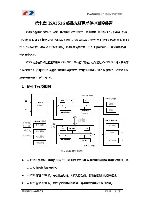
第七章 ISA353G线路光纤纵差保护测控装臵353G为输电线路的光纤纵差、电流电压保护及测控一体化装臵,采用标准4U(半层)机箱,由交流(WB7151)、管理CPU(WB720)、保护CPU(WB721)、操作(WB740B)、电源(WB760B)等5个插件组成,使用WB706总线板。
353G按面向对象、无人值班思想设计,既可分散安装,也可集中组屏。
353G的通信口标准配臵采用单CANBUS、不带打印功能、校时通过CANBUS广播(只有两个通信端子),若需采用双通信接口或其他通信方式、或需打印功能(10个通信端子、如附图P07端子虚线所示),需订货注明。
1硬件工作原理图图1. 353G硬件原理图●WB7151交流板。
将来自现场CT、PT的交流电气量,经辅助变换器隔离,并转换成电压,送入CPU板的模数转换元件。
●WB720管理CPU板。
完成测控功能、人机对话功能、各种自检及其他相关逻辑。
●WB721保护CPU板。
完成保护逻辑判断功能、各种自检及其光纤通讯功能。
●WB740B操作板。
完成带隔离的保护开出与遥控开出,带一个断路器的三相操作回路。
保护开出与遥控开出经外部接线作用到操作回路,可分别经外部压板投退。
●WB706总线板。
由128*64大屏幕带背光液晶显示屏及按键构成,主要实现人机对话。
液晶显示屏能实时显示各种运行状态量及人机对话的菜单、数据等。
在面板上的指示灯用于指示装臵的运行状况。
●WB760板。
为装臵提供工作电源;具有20路空接点开入(其中8路使用保护电源);可发信号继电器,包括动作、告警、装臵异常。
2保护配臵说明本装臵提供了非常丰富的保护元件,能够满足用户的各种要求,保护元件有:● 相电流越限记录 ● 差流越限告警 ● 分相纵差保护● 三段式低电压闭锁方向过电流保护(方向元件、低压元件均可单独整定) ● 低压闭锁相电流加速段保护 ● 小接地零序方向过流保护 ● 滑差/无滑差闭锁低周减载 ● 低压减载● 三相一次重合闸● CT 断线告警及闭锁差动保护 ● 控制回路断线告警 ● 母线PT 断线告警 ● 线路PT 断线告警 ● 过负荷保护● 四段直接接地零序方向过流保护 ● 零序过流后加速保护 ● 外部跳闸开入保护 ● 外部告警开入保护 ● 手合同期元件2.1 相电流越限记录元件相电流越限记录元件设独立的越限门坎定值d797,并按相记录各相电流的越限情况,产生独立的相电流越限记录。

The 375 Field Communicator is designed to supportall HART and all Foundation fieldbus devices from all vendors.Page 2Product DescriptionBuilding on the experience with the proven 275 HART Communicator,the 375 Field Communicator includes enhancements designed to simplify your work in the field.We designed the 375 Field Communicator user interface around the 275,leveraging the navigation features users told us they liked.Then we added powerful features including a much larger touch screen,HART Revision 6support,and the ability to upgrade your 375 Field Communicator onsite using the Internet.■See the difference.The 375 Field Communicator runs on Windows CE,a robust,real-time,operating system.The display is 70% larger than that of the 275HART Communicator and uses transflective technology,making it easy to read in both bright sunlight and in normal lighting.T o make sure we covered all conditions,we added a multi-level backlight,allowing the display to be viewed in those areas of your plant with dim light.The touch sensitive display and large physical navigation buttons provide for efficient use both on the bench and in the field.your attention,the 375 Field Communicator is also user upgradeable via the Internet.This means it is no longer necessary to send your communicator anywhere to have new device drivers added.A fold-away stand provides the correct viewing angle on the bench,and flips up to a locked position for secure hanging in the plant.With over 600 different HART and Foundation fieldbus devices from more than 100 different vendors,having a single field communicator that works with everything is a big help.So,grab the 375 Field Communicator and go!Page 3■Universal – HART and Foundation fieldbusThe 375 Field Communicator is designed to support all HART and Foundation fieldbus devices.If you are familiar with the 275HART Communicator,used in thousands of plants worldwide for more than ten years,you will appreciate universal HART support in a single intrinsically safe handheld communicator .The 375 Field Communicator can also be used to configure all the Foundation fieldbus devicesin your e it to perform diagnostics for effective start-up and troubleshooting of Foundation fieldbus segments.Create a quality segment by diagnosing the network DC voltage and average noise.Detect power supply problems by monitoring low frequency noise on a segment.Locate incorrect terminations and faulty devices by diagnosing the communications signal level.No longer do you need to drag a laptop computer out into the plant to communicate with yourFoundation fieldbus devices.Designed not only for use on the bench,the 375 Field Communicatorenables you to do those tasks that just have to be done in the field.As new HART and Foundation fieldbus DD’s become available,download them from the Internet and upgrade your 375 Field Communicator .In addition,as functional enhancements to the 375 HART and Foundation fieldbus applications become available,download software updates from the Internet and upgrade your 375 Field Communicator .No longer is it necessary to sendyour communicator to a service center to have new DD’s or software updates added.No longer is it necessary to be without your communicator while you wait for upgrades.Easy Upgrade lets you update your own 375 Field Communicator .On your site,within your control,when it’s convenient for you.■User upgradeableNew HART and Foundation fieldbus devices,as well as functional updates to existing devices are introduced continually by device vendors.Keeping up-to-date with the required Device Description drivers for all the devices in your plant can be a real challenge.Now,with the Easy Upgrade option,keeping your communicator updated with the most current Device Descriptions (DD’s) is easy .Page 4Easy Upgrade allows communication between the 375 Field Communicator and a PC using IrDA.The IrDA port enables transfer of configuration data between the 375 and AMS Device Manager as well as upgrading of new Device Descriptions and functionality.As for reliable,when was the last time you had to send your 275HART Communicator in for repair?That’s exactly the kind of reliability we’ve built into the 375.The 375Field Communicator is designed,manufactured and tested to specifications that are even more demanding.The 375 Field Communicator is designed to go wherever you have to go to get the job done.Even the battery pack is approved for installation in hazardous areas.The 375 Field Communicator is designed for use in areas where laptops shouldn’t go.■Rugged and Reliable.It’s called ‘Field Communicator’for a reason.Some tasks just have to be performed at the device.The 375 Field Communicator is designed for tough use in your plant or mill.Its large keys and physical navigation buttons allow for one-handed operation,even with your work gloves on.The rugged display is designed to take the knocks and shocks from normal use in the plant.■Intrinsically Safe.The 375 Field Communicator meets the Intrinsic Safety requirements of the listed regulatory agencies and standards.All of the available Hazardous Locations approvals are provided in a single model option (see Ordering Information).– CENELEC/ATEX – Factory Mutual (FM)– Canadian Standards Association (CSA)– FISCOPage 5SpecificationsMicroprocessor■80 MHz Hitachi ®SH3Memory Internal Flash ■32 MBSystem Card■128MB or higher secure digital card RAM■32 MBExpansion Module■32 MB or higher secure digital card Weight■Approximately 2 lb.(0.9kg) with battery Display■1/4 VGA (240 by 320 pixels)monochrome 3.8”(9.6 cm) transflective display with touch screen ■Anti-glare coatedKeypad■25 keys including 4 action keys,12 alphanumeric keys,4 programmable function keys,on/off,and 4cursor-control (arrow) keys;membrane design with tactile feedbackUsage■-10°C (14°F ) to +50°C (122°F ) ■0% to 95% RH (non-condensing)for 0°C (32°F ) to +50°C (122°F )Charge■0°C (32°F ) to +40°C (104°F )Storage■-20°C (-4°F ) to +55°C (131°F ) with batteries Storage Without Batteries■-20°C (-4°F ) to +60°C (140°F )Enclosure Rating ■IP51 (from front)Shock■Tested to survive a 1-meter drop test onto concrete Usage■PC with internet access ■CD Rom drive■IrDA port (or adapter)■Windows 2000 or XPBattery Pack■Rechargeable NiMH batteriesBattery Operating Time■Up to ten hours depending on usageBattery Charger Options■Input voltage 85-240 VAC,50/60 Hz ■Cables included with U.S.,European and U.K.plugs Battery Charger■Mini DIN 4-pin jackHART and Fieldbus■Three 4mm banana plugs (one common to HART and Foundation fieldbus)IrDA Port■IrDA (Infrared Data Access) port supporting up to 115 Kbps■±15 degrees recommended maximum angle from center line■Approximately 12”(30 cm)recommended maximum distancePage 6■Interfaces with AMS Suite:Intelligent Device Manager .The 375 Field Communicator is fully compatible with AMS Device Manager ,the industry standard for asset management software.In fact,Control Magazine readers selected AMS as the #1 Calibration Software package for 3years in a row .AMS Device Manager allows you to configure,streamline calibration,document and troubleshoot HART and Foundation fieldbus devices.of device configurations safely in your 375 Field Communicator .Together,the 375 FieldCommunicator and AMS Device Manager enable you to more efficiently manage all of your devices,the assets that are the foundation ofyour process.The Configuration Expansion AMS Device Manager uses the intelligence from field devices to create a predictive maintenance environment.Transfer device configuration data via the infrared port on the 375 Field Communicator and AMS Device Manager on your PC.Carry your 375 Field Communicator out to the field to configure or update one or many devices.Save device configurations in your 375 Field Communicator for safe storage or transfer to AMS Device Manager .The optional Configuration Expansion Modulestores hundredsModule safely stores hundreds o fdevice configurations.375 Field Communicator Spare Parts ListRuggedized 250 Ohm Load Resistor00275-0096-0001 Rechargeable NiMH Battery Pack with Accessory Case00375-0002-0011 Power Supply/Charger(90-240VAC,50/60Hz,US/UK/EU connection types included)00375-0003-0011 Lead Set with connectors 00375-0004-0001 Mounting Straps00375-0005-0002 Carrying Case (with straps) 00375-0005-0003 Accessory Case (clips to Carrying Case)00375-0005-0004 Stylus (pack of5)00375-0006-0001 IRDA to USB Adapter (1)00375-0015-0002 Expansion Port Plug00375-0031-0001 System Card - HART®and FOUNDATION™ fieldbus00375-0042-0002 System Card - HART with Easy Upgrade Option (2)00375-0042-0003 System Card - HART and Foundation fieldbuswith Easy Upgrade Option (2)00375-0042-0004 Configuration Expansion Module00375-0043-0001 Stand and Utility Plate00375-0044-0001 Getting Started Guide00375-0045-0001 User's Manual00375-0047-0001 Resource CD (3)00375-0049-0001(1)For use with AMS Device Manager/375 Interface or 375 Easy Upgrade Programming Utility.(2) Includes unlimited upgrades to System Card for 3 year period.(3) Contains 375 Programming Utility and System Software/DD database.This CD is updated quarterly.Shipping Weight (varies with options)71 lbs/3.2 kg (based on 375HR1EKLU)Page 7375 Field Communicator Ordering Information Model Product Description375Field Communicator (1)Code Communication ProtocolH HART®F HART and Foundation fieldbus (2)Code Battery TypeR Rechargeable NiMH Battery PackCode Power Supply/Recharger1Power Supply/Recharger(90/240 VAC,50/60Hz,US/UK/EU connection types included) 9Not includedCode LanguageE English (standard)Code Approval CertificationsKL CENELEC/ATEX,FM,CSA Intrinsically Safe(includes FISCO as applicable)NA No ApprovalCode Easy Upgrade(4)U Easy Upgrade Option(includes unlimited upgrades to System Card for 3 year period) 9Not IncludedCode OptionsSpare Battery PackB Spare Rechargeable NiMH Battery Pack (5)Expansion ModuleC Configuration Expansion Module (6)Typical Model Number:375 H R 1 E KL U(1)Base Model 375 includes Field Communicator Unit with Battery Pack,System Card,Leadset with Connectors,Carrying Case,Getting Started Guide,User’s Manual,375 Resource CD,Stylus and Straps.(2)Requires that the Easy Upgrade Option (CODE U) also be purchased.(3)This option should only be considered if the user already has a 375 PowerSupply/Charger.Note:Only 375 Power Supply/Chargers may be usedwith the 375 Battery Pack.(4)The Easy Upgrade capability allows the user to add new System Applicationsoftware and Device Descriptions (DD’s) to the 375.To upgrade without thisfeature,the System Card must be sent a Service Center.(5) A fully charged battery pack is capable of delivering power for 8 hoursof typical field use.If requirements exceed this specification,a secondbattery pack is recommended.(6)The 375 is capable of storing a total of25 configurations.For increasedstorage capacity,use the Configuration Expansion Module which is capableof storing in excess of500 configurations. ©2004,Emerson Process Management.The contents of this publication are presented for informational purposes only,and while every effort has been made to ensure their accuracy,they are not to be construed as warranties or guarantees, express or implied,regarding the products or services described herein or their use or applicability. All sales are governed by our terms and conditions,which are available on request.We reserve the right to modify or improve the designs or specifications of our products at any time without notice.All rights reserved.AMS is a mark of one of the Emerson Process Management group of companies. The Emerson logo is a trademark and service mark of Emerson Electric Company.All other marks are the property of their respective owners.Emerson Process Management Asset Optimization Division 12001 Technology DriveEden Prairie,MN 55344 USA T 1(512)832-3235F1(952)828-3033。

运放参数解释及常用运放选型集成运放的参数较多,其中主要参数分为直流指标和交流指标,外加所有芯片都有极限参数。
本文以NE5532为例,分别对各指标作简单解释。
下面内容除了图片从NE5532数据手册上截取,其它内容都整理自网络。
极限参数主要用于确定运放电源供电的设计(提供多少V电压、最大电流不能超过多少),NE5532的极限参数如下:直流指标运放主要直流指标有输入失调电压、输入失调电压的温度漂移(简称输入失调电压温漂)、输入偏置电流、输入失调电流、输入偏置电流的温度漂移(简称输入失调电流温漂)、差模开环直流电压增益、共模抑制比、电源电压抑制比、输出峰-峰值电压、最大共模输入电压、最大差模输入电压。
NE5532的直流指标如下:输入失调电压Vos输入失调电压定义为集成运放输出端电压为零时,两个输入端之间所加的补偿电压。
输入失调电压实际上反映了运放内部的电路对称性,对称性越好,输入失调电压越小。
输入失调电压是运放的一个十分重要的指标,特别是精密运放或是用于直流放大时。
输入失调电压与制造工艺有一定关系,其中双极型工艺(即上述的标准硅工艺)的输入失调电压在±1~10mV之间;采用场效应管做输入级的,输入失调电压会更大一些。
对于精密运放,输入失调电压一般在1mV以下。
输入失调电压越小,直流放大时中间零点偏移越小,越容易处理。
所以对于精密运放是一个极为重要的指标。
输入失调电压的温度漂移(简称输入失调电压温漂)ΔVos/ΔT输入失调电压的温度漂移定义为在给定的温度范围内,输入失调电压的变化与温度变化的比值。
这个参数实际是输入失调电压的补充,便于计算在给定的工作范围内,放大电路由于温度变化造成的漂移大小。
一般运放的输入失调电压温漂在±10~20μV/℃之间,精密运放的输入失调电压温漂小于±1μV/℃。
输入偏置电流Ios输入偏置电流定义为当运放的输出直流电压为零时,其两输入端的偏置电流平均值。
Document No. IC-3429 (O. D. No. IC-9002)Date Published August 1994 P Printed in Japan ©19942BLOCK DIAGRAMOD V OUT AGNDDGNDφ2φTGφ13PIN CONFIGURATION (Top View)CCD LINEAR IMAGE SENSOR 22 PIN PLASTIC DIP (400 mil)PHOTOCELL STRUCTURE DIAGRAMφ12222132041951861771681591410131112No connectionNo connectionAnalog GNDOutputNo connectionNo connectionNo connectionShift register clock 2Shift register clock 1Digital GNDNo connectionNo connection No connection Output unit drain voltage No connection No connection No connection No connection No connection Transfer gate clock No connection No connection NC V NC NC NCNC NCNC NC NC NC DGND2NC NCOUT 1NC NC TGφAGND φOD V NCABSOLUTE MAXIMUM RATINGS (T a = +25 °C)RECOMMENDED OPERATING CONDITIONS (T a = –25 to + 60 °C)Caution When VφTGH > Vφ1H, image lag increases.4ELECTRICAL CHARACTERISTICST a = +25 °C, V OD = 5 V, fφ1 = 1 MHz, data rate = 1 MHz, storage time = 10 mslight source: 3200 K halogen lamp + C500 (infrared cut filter), input clock = 5 V P-PRemark When V OD = 4.7 V, the response typically decreases to 90 % of the value under 5 V operation.56TIMING CHART 1TIMING CHART 2φTGφ1φ2V OUTCaution Be sure not to use this period (indicated by *) as the black level, because this part is unstable.φ1φ2V OUTRemark : Signal output7TIMING CHART for φTG, φ1, φ2NoteAdjust cross point of φ1, φ2 by φ1, φ2 pin external input resistors.(Unit: ns)TG1212φφφφφRemark The MAX. in the table above shows the operation range in which the output characteristics are kept almost enough for general purpose, does not show the limit above which the µPD3753 is destroyed.8DEFINITIONS OF CHARACTERISTIC ITEMS1.Saturation voltage: V satOutput signal voltage at which the response linearity is lost.2.Saturation exposure: SEProduct of intensity of illumination (lx) and storage time (s) when saturation of output voltage occurs.3.Photo response non-uniformity: PRNUThe peak/bottom ratio to the average output voltage of all the valid bits calculated by the following formula.–1PRNU (%) =n :Number of valid bits V j :Output voltage of each bitx 100V j=1n 4.Average dark signal: ADSOutput average voltage in light shielding.1n V j j =1n ∑ADS(mV) =5.Dark signal non-uniformity: DSNUThe difference between peak or bottom output voltage in light shielding and ADS.96.Output impedance: Z oOutput pin impedance viewed from outside.7.Response: ROutput voltage divided by exposure (lx •s).Note that the response varies with the light source.8.Image Lag: ILThe rate between the last output voltage and the next one after read out the data of a line.V OUTLightTGφ9.Bit Noise: BNOutput signal distribution of a photocell by scan.101200600400100080020406080100SPECTRAL RESPONSE CHARACTERISTICWavelength (nm)R e s p o n s e R a t i o (%)STANDARD CHARACTERISTIC CURVES (T a = +25 °C)10203040500.10.25120.54851010.10.212STORAGE TIME OUTPUT VOLTAGE CHARACTERISTICDARK OUTPUT TEMPERATURE CHARACTERISTIC Ambient Temperature T ( C)a °R e l a t i v e O u t p u t V o l t a g eR e l a t i v e O u t p u t V o l t a g eStorage Time (ms)11110100904.74.55.05.3 5.5POWER SUPPLY VOLTAGE RESPONSE RATIO CHARACTERISTICR e s p o n s e R a t i o (%)Power Supply Voltage (V)12APPLICATION EXAMPLEThe application circuits and their parameters are for references only and are not intended for use in actual design-in's.V OUT13PACKAGE DIMENSIONSCCD LINEAR IMAGE SENSOR 22PIN PLASTIC DIP (400 mil)1The bottom of the package The surface of the chip2The thickness of the cap over the chip22C-1CCD-PKG2(Unit : mm)0.25RECOMMENDED SOLDERING CONDITIONSThe following conditions (see table below) must be met when soldering this product.For more details, refer to our document “SEMICONDUCTOR DEVICE MOUNTING TECHNOLOGY MANUAL”(IEI-1207).Please consult with our sales offices in case other soldering process is used, or in case soldering is done under different conditions.Table 1 Type of Through Hole DeviceµPD3753CY:CCD LINEAR IMAGE SENSOR 22 PIN PLASTIC DIP (400 mil)Caution Do not jet molten solder on the surface of package.1415[MEMO]No part of this document may be copied or reproduced in any form or by any means without the prior written consent of NEC Corporation. NEC Corporation assumes no responsibility for any errors which may appear in this document.NEC Co rpo ratio n do es no t assume any liability fo r infringement o f patents, co pyrights o r o ther intellectual property rights of third parties by or arising from use of a device described herein or any other liability arising fro m use o f such device. No license, either express, implied o r o therwise, is granted under any patents, copyrights or other intellectual property rights of NEC Corporation or others.The devices listed in this document are not suitable for use in aerospace equipment, submarine cables, nuclear reactor control systems and life support systems. If customers intend to use NEC devices for above applicationsor they intend to use "Standard" quality grade NEC devices for applications not intended by NEC, please contact our sales people in advance.Application examples recommended by NEC CorporationStandard:Co mputer, Office equipment, Co mmunicatio n equipment, Test and Measurement equipment, Machine tools, Industrial robots, Audio and Visual equipment, Other consumer products, etc.Special:Automotive and Transportation equipment, Traffic control systems, Antidisaster systems, Anticrime systems, etc.M4 92.6This datasheet has been download from: Datasheets for electronics components.。
375中文说明书范文P(1)用户手册375型现场通讯器用户手册375型现场通讯器P(2)P(3)用户手册00375-0047-0001,Rev.C2004年2月375型现场通讯器375型现场通讯器注意使用375型现场通讯器之前,请阅读用户手册。
为保证人身安全和系统安全,以及发挥产品的最佳性能,使用或维修本产品之前,请深入掌握相应内容。
2004艾默生过程管理。
保留所有权利。
艾默生标志为艾默生电气公司的商标和服务标志。
AMS软件包为艾默生电气公司的商标。
罗斯蒙特和SMARTFAMILY为罗斯蒙特有限公司的注册商标。
Window 为美国和其他国家微软公司的注册商标。
IrDA为红外数据协会的注册商标。
FOUNDATION为现场总线基金会的商标。
HART为HART通信基金会的注册商标。
Hitachi为Hitachi美国有限公司的注册商标。
所有其他商用标志的所有权归其各自的所有者。
正在申请美国和其他国家的专利号。
P(5)用户手册00375-0047-0001,Rev.C2004年2月375型现场通讯器目录第一节简介本手册的使用............................................................. ......1-1第二节掌握基本知识概述............................................................. ..............2-1安全信息............................................................. .......2-1安装系统卡和电池组...........................................................2-2启动和关闭............................................................. .....2-3启动375型现场通讯器.......................................................2-4关闭............................................................. .......2-4基本性能和功能............................................................. ...2-5键区的使用............................................................. .2-6开/关键............................................................. ..2-6箭头导航键...........................................................2-6回车键............................................................. ..2-6Tab 键............................................................. ...2-6字母数字按键区.......................................................2-7背光调节键............................................................. .2-7功能键............................................................. ....2-8多功能LED.. (2)-8使用触摸屏.............................................................2-8使用软输入面板(SIP)键盘..............................................2-9浏览375的主菜单 (2)-9启动HART应用...........................................................2-10启动现场总线应用..........................................................2-10TOC-2运行Setting菜单...........................................................2-10关于375............................................................ ...2-10背光............................................................. ....2-11时钟............................................................. .....2-11对比度............................................................. ....2-11事件捕获............................................................. .2-12证书............................................................. ....2-13内存............................................................. .....2-13电源............................................................. ....2-13触摸屏对齐...........................................................2-14返回到375主菜单.......................................................2-14与PC的通信............................................................. .2-14与PC的IrDA通信........................................................2-14PC控制方式...........................................................2-15利用AMS软件包智能设备管理器传送HART组态..............................2-16快捷升级编程工具.....................................................2-16使用ScratchPad应用程序....................................................2-17创建新文档 (2)-18打开已有文档..........................................................2-18输入文本............................................................. .2-18选择文本............................................................. 2-18剪切文本............................................................. .2-19拷贝文本............................................................. 2-19粘贴文本............................................................. .2-19撤消文本............................................................. 2-19保存文档.............................................................. 2-19保存副本. (2)-20删除文档 (2)-20退出ScratchPad...................................................... ..2-20管理储存............................................................. ......2-21储存类型 (2)-21维护............................................................. ..........2-22电池信息............................................................. ..2-22检查充电量.........................................................2-22电池充电...........................................................2-23取出系统卡和电池组..................................................2-23运行自检测.............................................................2-24本质安全(IS)区域的操作.................................................2-24目录TOC-3废物处理............................................................. .2-24第3节HART功能概述............................................................. .............3-1安全信息............................................................. ........3-1基本性能和功能............................................................. ..3-2理解HART图标.......................................................3-2启动HART应用程序............................................................. 3-2使用快捷键次序...........................................................3-2设置热键选项............................................................. 3-3执行热键选项............................................................. 3-4一次删除一个热键选项.....................................................3-4删除所有热键选项..........................................................3-4离线操作............................................................. ........3-5离线创建新组态...........................................................3-5打开已保存的离线组态.....................................................3-7编辑已保存的离线组态...................................................3-8拷贝已保存的离线组态.....................................................3-9发送已保存的离线组态.....................................................3-9删除已保存的离线组态....................................................3-9重命名已保存的离线组态....................................................3-10比较两个已保存的离线组态.................................................3-10在线操作............................................................. .......3-11与HART回路的连接......................................................3-11查看在线菜单............................................................. .....3-14查看DeviceSetup子菜单..................................................3-16过程变量(PV)......................................................3-16诊断和服务.........................................................3-16基本设置 (3)-17详细设置...........................................................3-17浏览............................................................. ..3-17一级变量(PV)......................................................... 3-18模拟输出(AO)......................................................... .3-18下限值(LRV)........................................................ ..3-18上限值(URV)........................................................ .3-18查看Utility菜单............................................................. ..3-18组态HART应用程序.........................................................3-18修改HART轮询选项...................................................3-18修改忽略的状态信息..................................................3-20存储清除 (3)-20查看所有的设备描述......................................................3-21仿真HART设备的在线连接...................................................3-21查看HART诊断..........................................................3-22DC电压测量(HART端子).............................................3-22断开HART 设备...........................................................3-22第4节现场总线功能概述............................................................. ............4-1安全信息............................................................. ........4-1基本性能和功能............................................................. ..4-2链路活动调度器(LAS)..................................................4-2互操作性............................................................. ....4-3375与其他主机的操作.....................................................4-3ST_REV........................................................ .........4-3模式............................................................. .....4-4模式的类型..........................................................4-4找出模式参数.......................................................4-5更改模式 (4)-5允许模式..........................................................4-5启动现场总线应用程序.........................................................4-6在线操作............................................................. ......4-7与现场总线回路的连接......................................................4-7Bench连接.........................................................4-9现场连接..........................................................4-10显示在线设备列表........................................................4-11显示块列表............................................................. .4-12设备块的操作 (4)-13参数的功能性........................................................4-13修改和发送参数数据...................................................4-14运行模式(例如校准,传感器调整,诊断等)..................................4-15显示设备状态.........................................................4-15其他块列表选项...........................................................4-15详细菜单..........................................................4-15更改I/O块调度.......................................................4-16显示先进性能........................................................4-17Utility........................................................ ..............4-17轮询............................................................. ........4-17查看已安装的现场总线设备描述...............................................4-18现场总线诊断............................................................. ..4-18断开现场总线设备........................................................4-19第5节故障排除概述............................................................. ..........5-1故障排除建议............................................................. 5-1路............................................................. .....5-2样本值............................................................. ...5-3错误和状态信息............................................................. ..5-5技术支持所需的信息..........................................................5-9附录A参考信息处理器和内存的技术规范......................................................A-1微处理器............................................................. ...A-1内存............................................................. ......A-1内部Flah........................................................... A-1系统卡............................................................. .A-1RAM........................................................... .....A-1扩展模块............................................................A -1物理性能指标............................................................. ..A-1量............................................................. ......A-1显示............................................................. ......A-1键盘............................................................. ......A-2电源技术指标............................................................. ...A-2电源电压............................................................A -2电池............................................................. ...A-2电池工作时间........................................................A-2电源/充电器..........................................................A-2连接规范............................................................. ........A-2电池充电器..........................................................A-2HART和现场总线通信..................................................A-2个人计算机..........................................................A-2环境指标............................................................. ........A-3使用............................................................. ..A-3充电............................................................. ..A-3存储............................................................. ...A-3存储(无电池).......................................................A-3机壳标准............................................................A -3抗冲击............................................................. .A-3订购信息............................................................. .......A-4备件列表............................................................. ..A-5附录B认证信息概述............................................................. ............B-1许可生产地点............................................................. ....B-1欧洲指令信息............................................................. ....B-1电磁兼容性(89/336/EWG).............................................B-1ATE某指令(94/9/EC)(仅适用于KL选项)...............................B-1其他重要指导原则.....................................................B-1危险场所认证(仅适用于KL选项)................................................B-2北美认证............................................................. ....B-2工厂互认(FM)........................................................B -2加拿大标准协会(CSA)...............................................B-2欧洲认证............................................................. ..B-3ATE某本质安全......................................................B-3HART 本质安全电气参数.................................................B-3基金会现场总线........................................................B-3索引............................................................. ..I-1用户手册00375-0047-0001,Rev.C2004年2月375型现场通讯器第一节简介本手册的使用本手册该部分包括375现场通讯器的连接和操作方面的内容。