液晶显示模块开基本步骤
- 格式:doc
- 大小:131.00 KB
- 文档页数:6
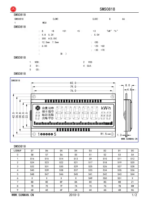
◆SMS0818液晶显示模块的概述:SMS0818数码笔段型液晶显示模块(LCM),采用数码笔段型液晶显示器(LCD),可显示8位数字及66段提示符及1个小数点,低功耗,与MCU单片机采用三线式串口连接,广泛应用于智能电表。
◆SMS0818液晶显示模块的主要技术参数:显示容量: 8位数字+8组汉字+51段条状图+5段圆形标志+3段符号(”kW”“.h”和小数点)模块工作电压: 4.8~5.2V 模块最佳工作电压: 5.0V工作电流: 300μA(5.0V)字高: 12.5mm 7.5mm 环境相对湿度:<85%视角: 6:00 工作温度:-20~+60℃显示方式: 反射式正显示存储温度:-30~+70℃接口方式: 三线式串行接口(B型)◆SMS0818液晶显示模块的接口信号说明:1 VDD: 电源正极2 VSS电源地3 DI: 串行数据输入4 CLK:串行移位脉冲输入5 CS: 片选信号输入LCDBUF D7 D6 D5 D4 D3 D2 D1 D00 S8 S7 S6 S5 S1 S2 S3 S41 S16 S15 S14 S13 S9 S10 S11 S122 S24 S23 S22 S21 S17 S18 S19 S203 S32 S31 S30 S29 S25 S26 S27 S284 S40 S39 S38 S37 S33 S34 S35 S365 S48 S47 S46 S45 S41 S42 S43 S446 X X X X S49S51XS507 8D 8E 8F 8A 8C 8G 8B Z18 7D 7E 7F 7A 7C 7G 7B KW9 6D 6E 6F 6A 6C 6G 6B H6。
OLED显示模块(原理讲解STM32实例操作)OLED(Organic Light Emitting Diode)显示模块是一种采用有机材料发光的显示技术。
与传统的液晶显示模块相比,OLED显示模块具有更高的亮度、更高的对比度、更快的响应速度和更广的可视角度。
在本文中,将介绍OLED显示模块的工作原理,并提供STM32实例操作。
OLED显示模块由若干个发光元素组成,每个发光元素都是一个发光二极管。
每个发光二极管由一层有机材料组成,当电流通过二极管时,有机材料会发光。
OLED显示模块的每个像素点都是一个发光二极管,通过控制每个像素点的电流大小,就可以实现对每个像素点的亮度控制。
步骤1:准备硬件和软件环境准备一块STM32开发板、一块OLED显示模块和STCubeMX软件。
连接OLED显示模块到STM32开发板,并使用STCubeMX软件配置STM32开发板的引脚。
步骤2:编写代码使用MDK-ARM工具或其他编程软件,编写STM32的驱动代码。
驱动代码包括初始化函数和控制函数。
初始化函数用于设置OLED显示模块的参数,如亮度、对比度等。
控制函数用于向OLED显示模块发送命令和数据,以控制每个像素点的亮度。
步骤4:测试和调试将STM32开发板连接到电源,并通过串口或其他方式,打开终端软件。
在终端软件中输入控制命令,通过STM32开发板向OLED显示模块发送命令和数据。
观察OLED显示模块上的显示效果,通过调试和测试,优化代码,实现预期的功能。
通过以上步骤,我们可以在STM32开发板上操作OLED显示模块。
根据实际需求,可以实现不同的功能,如显示文本、显示图像等。
总结:OLED显示模块是一种先进的显示技术,具有很高的亮度、对比度和响应速度。
通过STM32微控制器的控制,可以操作OLED显示模块,并实现各种功能。
利用STM32实例操作OLED显示模块,可以进一步了解OLED 显示技术的原理和应用。
基于STM32的LCD操作STM32的LCD操作是通过使用外部的液晶显示器(Liquid Crystal Display,简称LCD)模块来实现的。
以下是一个基于STM32的LCD操作的详细解释,包括液晶显示器的初始化、数据和命令的发送、以及常用的LCD操作函数。
LCD初始化:1.首先,配置GPIO引脚用于连接到LCD模块的数据线和控制线。
3.然后,发送各种初始化命令,如清除显示、设置光标等。
数据和命令的发送:1.向LCD发送数据(字符或图形数据)时,需要确保LCD处于数据接收状态,而不是指令接收状态。
通常需要在发送数据之前发送一个命令来设置LCD的模式为数据接收模式。
2.通过配置GPIO引脚的电平来发送数据或命令。
常用的LCD操作函数:1. `lcd_init(`: 初始化LCD模块。
2. `lcd_cmd(uint8_t cmd)`: 向LCD发送一个命令。
3. `lcd_data(uint8_t data)`: 向LCD发送一个数据。
4. `lcd_clear(`: 清除LCD显示内容。
5. `lcd_set_cursor(uint8_t row, uint8_t col)`: 设置LCD显示的光标位置。
6. `lcd_print(char *str)`: 在LCD上打印一个字符串。
7. `lcd_create_custom_char(uint8_t location, uint8_t *data)`: 创建自定义字符。
8. `lcd_display_on(`: 打开LCD显示。
9. `lcd_display_off(`: 关闭LCD显示。
上述函数只是基本的示例,具体的函数实现会因不同的液晶模块而有所不同。
在编写代码时,需要根据液晶模块的规格和数据手册来设置相应的GPIO引脚和参数。
总之,基于STM32的LCD操作涉及到GPIO引脚的配置、LCD控制器的初始化、发送数据和命令等步骤。
通过熟悉液晶模块的规格和使用相关的库函数,可以实现对LCD模块的控制。
DOT MATRIXLIQUID CRYSTAL DISPLAYMODULECOMPANY NAME : 伍豐科技USER‘MANUALSBS02002D0 SerialSBS02002D0LEW10(英日英日文版文版) LCD Module Description: SBS02002D0LEW20(英歐英歐文版文版)SBS02002D0LEW30(英俄英俄文版文版)PROPOSED BYAPPROVEDDesignApprovedSDEC TECHNOLOGY CORP.ADDRESS: 10F, No. 100, Shing De Rd., San Chung City 241Taipei Hsien, Taiwan R.O.C.TEL: 886-2-2999-2512/886-2-8512-1288 FAX: 886-2-2999-2510/886-2-8512-2828LCM SAMPLE APPROVAL (液 晶 顯 示 模 組組 樣 品 確 認 書)1. P ART A:FILLED BY SDEC TECH (由SDEC 填寫填寫))1) COMPANY NAME (客戶名稱客戶名稱):):):伍豐科技股份有限公司伍豐科技股份有限公司2) SDEC ITEM NO.(產品型號產品型號)):SBS02002D0LEW10/SBS02002D0LEW20/SBS02002D0LEW30 3) CUSTOMER ITEM NO.(客戶產品型號客戶產品型號)):RD9000PH03AJ/RD9000PH03AI/RD9000PH03AK 4) LCM Function (LCM 內容):ALCD TYPE (LCD 種類):□ TN, □ HTN, ■ STN, □ FSTN ( □ POSITIVE/正向正向,,■ NEGATIVE/反向, □ BLACK MASK/內黑絲印) B VIEWING AREA (視角方向):□ 3H, □ 6H, □ 9H, ■ 12HC POLARIZER COLOR (偏光板顏色):□ GRAY/灰色, □ YELLOW GREEN/黃綠色黃綠色,,■ BLUE/藍色, □ BLACK/黑色D BACKLIGHT COLOR (背光顏色):□ YELLOW GREEN/黃綠光, □ ORANGE/橘光□ RED/紅光, □ BLUE/藍光, □ GREEN/翠綠光, ■ WHITE/白光E TEMPERATURE (溫度):□ NORMAL/常溫, ■ WIDE/廣溫F Rom Code CheckSum :AF37H (Check Sum is not Read Back).GSBS02002D0LEW10 : SPLC780D1-01 CONTROL IC (控制IC): SBS02002D0LEW20 : SPLC780D1-03SBS02002D0LEW30 : SPLC780D1-02 SAMPLE DELIVERY DATE (出樣日期出樣日期):):2010.09.20 2.PART B:FILLED BY CUSTOMER (請客戶填寫請客戶填寫))CHECK LIST ITEMS (檢查項目檢查項目):):OK NG REASON (原因原因)) 1).LCM SIZE AND THICKNESS:(LCM 尺寸及厚度尺寸及厚度)): □ □ ________ 2).POLARIZER COLOR :(:(偏光板色澤偏光板色澤偏光板色澤):): □ □ ________ 3).ELECTRO CHARACTERISTIC :(:(電氣特性電氣特性電氣特性):): □ □ ________ 4).VIEWING AREA (視角範圍視角範圍):):□ □ ________ 5).BACKLIGHT ILLIMINATION (背光亮度背光亮度):): □ □ ________ 6).TEMPERATURE RANGE (溫度範圍溫度範圍):):□□________APPROVED BY (批准批准):): DATE OF APPROVAL (批准日期批准日期):):REVISION RECORDRevisionPage Contents2008.07 Mass Production2009.03A1. Change Instruction Code Table2. Add “€”Pattern in Font Table 07H & 0FH3. PCB R15~R25:100Ω change to 0Ω 2009.05A2 1. Add Customer Item No. 2 2. Add Rom code CheckSum.3. PCB Rev No :Rev.3 up date to Rev.4 2010.09A1. Initial Delay 30ms2. PCB U4:AT89C2051 change to SM894051C 23. CheckSum :AF37HCONTENTSPAGE ●LCM Sample Approval 2●REVISION RECORD 31. Mechanical Specification 52. Mechanical Diagram 53. Interface Pin Connections 54. Block Diagram 55. Backlight Electronic Characteristics 56. Absolute Maximum Ratings 67. Electrical Characteristics 68. Optical Characteristics 69. Optical Definitions 610. Instruction Set 711.Instruction Description 812. User Font Patterns 1113. Character Generator ROM Map13.1 SBS02002D0LEW10 Font Table 1213.2 SBS02002D0LEW20 Font Table 1313.3 SBS02002D0LEW30 Font Table 1414. Reliability Condition 1515. Function Test & Inspection Criteria 1516. Test – Normal Temperature 1817. Test – Wide Temperature 1918. Precautions Against Product Handling 2019. Warranty 211.Mechanical SpecificationITEM STANDARD VALUE UNITNUMBER OF CHARACTERS 20 CHARACTERS X 2 LINES --CHARACTER FORMAT 5 X 8 DOTS --MODULE DIMENSION167.0 (W) X 46.0 (H) X 18.5(Max) (T) mm EDGE LED BACKLIGHTVIEWING DISPLAY AREA 123.0 (W) X 23.0 (H) mmACTIVE DISPLAY AREA 118.85 (W) X 19.0 (H) mmCHARACTER SIZE 4.85 (W) X 9.32 (H) mmCHARACTER PITCH 6.00 (W) X 9.77 (H) mmDOT SIZE 0.93 (W) X 1.11 (H) mmDOT PITCH 0.98 (W) X 1.16 (H) mmNO SYMBOL FUNCTION1 VDD DC +5V2 VSS GND ( 0V)3 DI Series Data Input4 FGND FRAME GND5. Backlight Electronic CharacteristicsTa=25℃ITEM SYMBOL Ratings UNIT Absolute maximum forward current IFm 2*80 mA Peak forward current IFp 2*160 mAReverse Voltage Vr 4 VPower Dissipation Pd 2*160 mW Operating Temperature Range Top -20~+70 ℃Storage Temperature Range Tst -30~+80 ℃ITEM SYMBOL MIN. TYPE MAX. UNIT CONDITION Forward Voltage VF 3.8 4.0 4.2 V IF=2*40mAReverse Current Ir -- -- 2*200 μA Vr=4VLuminance LV 500 600 -- cd/m2IF=2*40mARange X=0.25~0.29 , Y=X-0.0135~X+0.0175 IF=2*40mA6. Absolute Maximum RatingsITEM SYMBOLMIN. TYPE MAX. UNIT INPUT VOLAGEVI VSS ── VDD V SUPPLY VOLTAGE FOR LOGIC VDD-VSS ── 5.0 6.5 V SUPPLY VOLTAGE FOR LCD VDD-VO ── ── 6.5 V NORMAL TEMPERATURE RANGE OPTERATING 0~+50 STORAGE -10~+60 ℃ TN HTN WIDE TEMPERATURE RANGE OPTERATING -20~+70 STORAGE -30~+80 ℃ STN FSTNWIDE TEMPERATURE RANGE OPTERATING-20~+70STORAGE-30~+80℃STATIC ELECTRICITYBe sure that you are grounded when handing LCM.7. Electrical CharacteristicsITEMSYN CONDITIONMIN. TYPE MAX. UNIT SUPPLY VOLTAGE FOR LOGIC VDD -VSS ── 4.5 5.0 5.5 V SUPPLY VOLTAGE FOR LCD VDD -VO Ta =-20℃ Ta =25℃ Ta =+70℃ ── 4.1 ── 4.9 4.3 3.9 ── 4.5 ── V V V INPUT HIGH VOLTAGE VIH ── 2.2 ── VDD V INPUT LOW VOLTAGE VIL ── 0 ── 0.6 V OUTPUT HIGH VOLTAGE VOH ── 2.4 ── ── V OUTPUT LOW VOLTAGE VOL ── ── ── 0.4 V SUPPLY CURRENT (Without Backlight)IDDVDD=+5V──3.04.5mA8. Optical Characteristics Ta at 25℃ITEMSYM CONDITIONMIN. TYPE MAX.UNIT VIEW ANGLE (TOP /BOTTOM) θ1~θ2 CR ≧5 -35o ── 45odeg. VIEW ANGLE (LEFT /RIGHT)φ1.φ2 CR ≧5 -35o ── 35o deg. CONTRAST RATIO CR ── ── 8 ── ── RESPONSE TIME (RISE) TON /Tr ── ── 170 ── mS RESPONSE TIME (DECAY)TOFF /Tf────220──mS9. Optical Definitions10. COMMAND SETC ommand C ode(hex)D escriptionESC @ 1B 40 Initialize.ESC _ n 1B 5F n (n=0, 1) Cursor hide/Show.HT 09 Cursor right.ESC [ C 1B 5B 43 Cursor right.BS 08 Cursor left.ESC [ D 1B 5B 44 Cursor left.LF 0A Cursor down.ESC [ B 1B 5B 42 Cursor down.ESC [ A 1B 5B 41 Cursor up.ESC [ H 1B 5B 48 Cursor homeHOM 0B Cursor homeCR 0D Cursor left-endESC [ L 1B 5B 4C Cursor left-end.ESC [ R 1B 5B 52 Cursor right-end.ESC [ K 1B 5B 4B Cursor to the bottom.ESC C n d0….d7 1B 43 n d0….d7 (00h<=n<=07h) Create custom character patternsESC l x y 1B 6C x y (01h<=x<=14h, 01h<=y<=02h) Cursor to specified position.CLR 0C Clear screen.ESC Q A 1B 51 41 [datax15] 0D Set string display mode, write string to upper line.ESC Q B 1B 51 42 [datax15] 0D Set string display mode, write string to lower line.ESC DC1 1B 11 Overwrite modeESC DC2 1B 12 Vertical scroll modeESC DC3 1B 13 Horizontal scroll modeCAN 18 Clear cursor line, clear string modeESC W s x1 x2 y 1B 57 s x1 x2 yS = 00h , 01h01h<=x1<=x2<=14h,Y = 01h , 02hSet/cancel the window range inHorizontal scroll modeThere are basically four display modes for the LCD. The user may choose the mode that is most appropriate for the application.Overwrite Mode:******************************************************************************************* from left to right, if it is at the end of the Line, it moves to the beginning of the other line. Characters are displayed at the Current cursor position, overwriting what is originally there, the cursor is then moved to the next position.Vertical Scroll Mode:If the cursor is at the upper line it behaves like the overwrite mode. When it is at the end of the lower line, the next character would scroll the content of the lower line to the upper line, the lower line is cleared and the cursor is moved to the beginning of the lower line.Horizontal Scroll Mode:In this mode the cursor stays in what ever line it is at, unless changed by cursor Movement commands. When the cursor is not at the end of the line, the input Character is displayed at current cursor position, the cursor is then moved right. Once at the end of the line, subsequent character input would scroll the current Line left one position, and the new character is displayed at the end position. There is also a command, ESC W, to set display window in this mode. The effective display line would be limited within the window as defined by the command.String Mode:This mode is perhaps the simplest used. The two display lines are treated independently. Only two commands, ESC Q A and ESC Q B, are needed. ESC Q A followed by a string on the upper line, left aligned. A CR (0DH) character terminates the command. If the string is less than twenty characters in length, the rest of display line is padded with plank. ESC Q B does the same for the lower display line. The only other commands active in this mode are CLR and CAN. CLR would clear the display and change the LCD into overwrite mode. CAN clears the last line that was changed and change the LCD into overwrite mode. The initialization command, ESC @, has no effect in this mode.11. Instruction Description11.1 ESC @ / Initialize display /ASCII Format:ESC @DEC Format:[027] [064]HEX Format:[1BH][40H]Description:Clear the data in the input buffer and reset setting to power on defaults.11.2 CLR / Clear display screen, and clear string mode /ASCII Format:CLRDEC Format:[012]HEX Format:[0CH]Description:Clear all the characters displayed, clear string mode.11.3 CAN / Clear cursor line, and clear string mode /ASCII Format:CANDEC Format:[024]HEX Format:[18H]Description:Clear the line where the cursor is at, clear string mode.11.4 ESC Q A d1d2d3…dn CR / Set string display mode, write string to upper line /ASCII Format:ESC Q A d1d2d3…dn CRDEC Format:[027][081] [065] d1d2d3…dn [013]HEX Format:[1BH] [51H] [41H] d1d2d3…dn [0DH] {20h<=dn<=ffh ,1<=n<=20}Description:Set string display mode, write to upper line.The string display mode can be cancelled with CLR or CAN.11.5 ESC Q B d1d2d3…dn CR / Set string display mode, write string to lower line /ASCII Format:ESC Q B d1d2d3…dn CRDEC Format:[027] [081][066] d1d2d3…dn [013]HEX Format:[1BH][51H][42H] d1d2d3…dn [0DH] {20h<=dn<=ffh ,1<=n<=20}Description:Set string display mode, write to lower line.The string display mode can be cancelled with CLR or CAN.11.6 ESC [ A / Move cursor up /ASCII Format:ESC [ ADEC Format:[027] [091] [065]HEX Format:[1BH] [5BH] [41H]Description:move the cursor up one line.When the cursor is at the upper line, this command operates differently depending on the display mode:a. Overwrite mode: The cursor is moved to the same column on the lower lineb. Vertical scroll mode: The characters displayed on the upper line are scrolled to the lower line, and the upper line iscleared. The cursor remains at the same position.c. Horizontal scroll mode: The cursor is not moved.11.7 ESC [ B / Move cursor down /ASCII Format:ESC [ BDEC Format:[027][091][066]HEX Format:[1BH][5BH][42H]Description:move the cursor down one line.When the cursor is at the lower line, this command operates differently depending on the display mode:a. Overwrite mode: The cursor is moved to the same column on the upper line.b. Vertical scroll mode: The characters displayed on the upper line are scrolled to the lower line, and the upper line iscleared. The cursor remains at the same position.c. Horizontal scroll mode: The cursor is not moved.11.8 ESC [ C / Move cursor right /HTASCII Format:ESC [ CHTDEC Format:[027][091][067][009]HEX Format:[1BH][5BH][43H][09H]Description:Move the cursor one position to the right.When the cursor is at the right end, this command operates differently depending on the display mode:a. Overwrite mode: The cursor moves to the left end of the other line.b. Vertical scroll mode: When the cursor is at the upper right end, it is moved to the lower left end. When the cursor is atthe lower right end, the lower line message is moved to the upper line. The lower line is cleared,and the cursor moved to the lower right end.c. Horizontal scroll mode: All characters on the current line are scrolled one to the left in the window. The cursor is notmoved but the character area at the right end of the windows is cleared.11.9 ESC [ D / Move cursor left /BSASCII Format:ESC [ DBSDEC Format:[027][091][068][008]HEX Format:[1BH][5BH][44H][08H]Description:Move the cursor one position to the left.When the cursor is at the left end, this command operates differently depending on the display mode:a. Overwrite mode: The cursor moves to the right end of the other line.b. Vertical scroll mode: When the cursor is at the lower left end, it is moved to the upper right end. When the cursor is atthe upper right end, the upper line message is moved to the lower line. The upper line is cleared,and the cursor moved to the upper right end.c. Horizontal scroll mode: All characters on the current line are scrolled one to the right in the window. The cursor is notmoved but the character area at the left end of the windows is cleared .11.10 ESC _ n / Set cursor ON or OFF /ASCII Format:ESC _ nDEC Format:[027] [095] n {0<=n<=1}HEX Format:[1BH] [5FH] nDescription:Set cursor ON or OFF.When n = 0, cursor is set to OFF.When n = 1, cursor is set to ON.11.11 ESC [ H / Move cursor to home position /HOMASCII Format:ESC [ HHOMDEC Format:[027][091][072][011]HEX Format:[1BH][5BH][48H][0BH]Description:Move the cursor to the left -most position on the upper line.11.12 ESC [ L / Move cursor to left-most position /CRASCII Format:ESC [ LCRDEC Format:[027][091][076][013]HEX Format:[1BH][5BH][4CH][0DH]Description:Move the cursor to the left-most position on the current line.11.13 ESC [ R / Move cursor to the right-most position /ASCII Format:ESC [ RDEC Format:[027][091][082]HEX Format:[1BH][5BH][52H]Description:Move the cursor to the right -most position on the current line.11.14 ESC [ K / Move cursor to the specified position /ASCII Format:ESC [ KDEC Format:[027][091][075]HEX Format:[1BH][5BH][4BH]Description:Move the cursor to the right -most position on the lower line.11.15 ESC l X Y / Move cursor to the specified position /ASCII Format:ESC l X YDEC Format:[027][108] X Y {01H<=X<=14H, 01H<=Y<=02H}HEX Format:[1BH][6CH] X YDescription:Move the cursor to the X-th column on the Y-th line.11.16 ESC W s x1 x2 y / Set or cancel the windows range at horizontal scroll mode /ASCII Format:ESC W s x1 x2 yDEC Format:[027][087][000][027][087][001] x1 x2 y {01h<=x<=14h , 01h<=y<=02h}HEX Format:[1BH][57H][00H][1BH][57H][01H] x1 x2 yDescription:Set or cancel the window range on the display screen.When s = 0, window is cancelled.When s = 1, window is set, where x1 and x2 set the position of the left-most and the right-most columns of thewindow.y sets the upper or lower line.The window is effective in the horizontal scroll mode.11.17 ESC C n d0….d7 / Create character pattern /ASCII Format:ESC C n d0….d7DEC Format:[027][067] n d0….d7 {00h<=n<=07h}HEX Format:[1BH][43H] n d0….d7Description:Create custom character patterns.n specifies which custom character to be generated.d0..d7 specify the bit pattern for the character to be generated.There are eight customer definable characters. They are numbered from 0 to 7, corresponding to character codes00h to 07h, and are duplicated at character codes 08h to 0Fh.The relation between n and the character codes is as below:n Char code N Char code0 00h 0 08h1 01h 1 09h2 02h 2 0Ah3 03h 3 0Bh4 04h 4 0Ch5 05h 5 0Dh6 06h 6 0Eh7 07h 7 0FhBelow is an example for generating as a custom character:NO 7 6 5 4 3 2 1 0 (Bit Pattern) Data Value in hexd0 * * * 1 1 1 1 1 1FHd1 * * * 1 0 0 0 1 11Hd2 * * * 1 0 0 0 1 11Hd3 * * * 1 0 0 0 1 11Hd4 * * * 1 0 0 0 1 11Hd5 * * * 1 0 0 0 1 11Hd6 * * * 1 0 0 0 1 11Hd7 * * * 1 1 1 1 1 1FH11.18 ESC DC1 / Set overwrite mode /ASCII Format:ESC DC1DEC Format:[027][017]HEX Format:[1BH][11H]Description:Set the display to overwrite mode. This is the default power on display mode.11.19 ESC DC2 / Set vertical scroll mode /ASCII Format:ESC DC2DEC Format:[027][018]HEX Format:[1BH][12H]Description:Set the display to vertical scroll mode.11.20 ESC DC3 / Set horizontal scroll mode /ASCII Format:ESC DC3DEC Format:[027][019]HEX Format:[1BH][13H]Description:Set the display to horizontal scroll mode.12. User Font Patterns ( CG RAM Character )Character Code (DD RAM data) CG RAM Address Character Pattern (CG RAM data) Hi 7 6 5 4 3 2 1 0 Lo 5 4 3 2 1 0 Hi 7 6 5 4 3 2 1 0 Lo0 0 0 0 x 0 0 00 0 00 0 10 1 00 0 0 0 1 11 0 01 0 11 1 01 1 1x x x 1 1 1 1 0x x x 1 0 0 0 1x x x 1 0 0 0 1x x x 1 1 1 1 0x x x 1 0 1 0 0x x x 1 0 0 1 0x x x 1 0 0 0 1x x x 0 0 0 0 00 0 0 0 x 0 0 10 0 00 0 10 1 00 0 1 0 1 11 0 01 0 11 1 01 1 1x x x 1 0 0 0 1x x x 0 1 0 1 0x x x 1 1 1 1 1x x x 0 0 1 0 0x x x 1 1 1 1 1x x x 0 0 1 1 0x x x 0 0 1 0 0x x x 0 0 0 0 0---------------- ---------------- --------------------------------0 0 0 0 x 1 1 10 0 00 0 10 1 01 1 1 0 1 11 0 01 0 11 1 01 1 113.Character Generator ROM Map13.1 SBS02002D0LEW10 (英日文版)Font Table13.2 SBS02002D0LEW20 (英歐文版)Font Table13.3 SBS02002D0LEW30 (英俄文版)Font Table14.Reliability Condition15.Functional Test & Inspection Criteria15.1 Sample planSample plan according to MIL-STD-105D level 2, and acceptance/rejection criteria is. Base on: Major defect: AQL 0.65 Minor defect: AQL 2.5 15.2 Inspection conditionViewing distance for cosmetic inspection is 30cm with bare eyes, and under an environment of 800 lus (20W) light intensity. All direction for inspecting the sample should be within 45°against perpendicular line.15.3 Definition of Inspection Zone in LCDZone A: Character / Digit area Zone B: Viewing area except Zone A (Zone A + Zone B = minimum Viewing area) Zone C: Outside viewing area (invisible area after assembly in customer’s product)Note: As a general rule, visual defects in Zone C are permissible, when it is no trouble forquality and assembly of customer’s product.15.4 Major DefectAll functional defects such as open (or missing segment), short, contrast differential, excess power consumption, smearing, leakage, etc. and overall outline dimension beyond the drawing. Are classified as major defects.15.5 Inspection Parameters And Glass Pixel(偏光板和玻璃圖像檢驗)NO Polarizer(偏光板) Criteria1Black or White spots And Piercing(黑/白點和刺孔)D/面積=(Length/長度+Width/寬度)/2 => * :Disregard(忽略)Dimension (面積) Acceptable number (可接受數量)D <0.15 * 0.15≦D ≦0.2 4 0.2≦D ≦0.25 2 D ≦0.30 2Scratch (刮傷)*0.04≧W * 3.0≧L 0.06≧W 4 2.0≧L 0.08≧W 2-0.1≧WX :Length(長度) Y :Width(寬度) *:Disregard(忽略)X(mm)Y(mm)Acceptable number (可接受數量)3Air Bubbles(between glass & polarizer) 氣泡(玻璃跟偏光板之間)D ≦0.15 * 0.15<D ≦0.25 20.25<D*:Disregard (忽略)Dimension (面積) Acceptable number (可接受數量)4Glass of Pixel (玻璃的圖像)(1)Pixel shape (with Dent) /圖像凹度●Less than 0.152 mm is no counted (小於0.152mm 者不計)(2)Pixel shape (with Projection)/圖像凹度Should not be connected next pixel(點與點間不可先連接)(3)Deformation/變形( X + Y ) / 2 ≦ 0.15mm ●Less than 0.1 mm is no counted (小於0.15mm 者不計)(4) Deformation/變形( X + Y ) / 2 ≦ 0.3mm ●Less than 0.3 mm is no counted (小於0.3mm 者不計)(在不改變原先顯示下進行以下測試操作)Conditions : Unless otherwise specified, test will be conducted under the following condition. Temperature : 20±5 ℃ Humidity : 40±5%RHTests will be not conducted under functioning state.(條件:除非其他特殊情況,否則測試將以溫度:20±5 ℃,濕度:40±5%RH 為主)NO ParameterConditionsNotes 1 High Temperature Operating50℃±2 ℃ , 96 hrs (operation state)(96小時,溫度50℃±2 ℃電源開啟的操作情況下) 2 Low Temperature Operating0℃±2 ℃ , 96 hrs (operation state)(96小時,溫度0℃±2 ℃電源開啟的操作情況下) 1 3 High Temperature Storage60℃±2 ℃ , 96 hrs(96小時,溫度60℃±2 ℃電源關閉靜態操作下) 2 4 Low Temperature Storage -10℃±2 ℃ , 96 hrs(96小時,溫度-10℃±2 ℃電源關閉靜態操作下) 1 , 2 5Damp ProofTest40℃±2 ℃ , 85 ~ 90%RH , 96hr(96小時,溫度:40℃±2 ℃,濕度:85~90%RH 電源關閉靜態操作下)1 , 26Vibration TestTotal fixed amplitude : 1.5 mm (完全固定輻射:1.5mm) Vibration Frequency : 10 ~ 55 Hz (震動頻率:10~55 Hz) One cycle 60 seconds to 3 directions of X , Y , Z foreach 15 minutes (每一個循環 X ,Y ,Z 軸方向各做60秒,連續做5次,共計15 分鐘)37Shock Test To be measured after dropping from 60cm high on the concrete surface in packing state. (包裝材從60公分高的地方向地面落下)Dropping method comer dropping (角落落下方式)A comer :once Edge dropping (側邊落下)B ,C ,D edge : onceFace dropping (表面落下)E ,F ,G face : onceNote 1:No dew condensation to be observed. (不要在”水氣凝結點”下觀察) Note 2:The function test shall be conducted after 4 hours storage at the normalTemperature and humidity after removed from the test chamber(從實驗室移出後,放在一般常溫 (溫度:25℃,濕度:45%RH), 且四小時後通電流或電壓,看它是否能正常動作)(在不改變原先顯示下進行以下測試操作)Conditions : Unless otherwise specified, test will be conducted under the following condition. Temperature : 20±5 ℃ Humidity : 40±5%RHTests will be not conducted under functioning state.(條件:除非其他特殊情況,否則測試將以溫度:20±5 ℃,濕度:40±5%RH 為主)NO ParameterConditionsNotes 1 High Temperature Operating70℃±2 ℃ , 96 hrs (operation state)(96小時,溫度70℃±2 ℃電源開啟的操作情況下) 2 Low Temperature Operating-20℃±2 ℃ , 96 hrs (operation state)(96小時,溫度-20℃±2 ℃電源開啟的操作情況下) 1 3 High Temperature Storage80℃±2 ℃ , 96 hrs(96小時,溫度80℃±2 ℃電源關閉靜態操作下) 2 4 Low Temperature Storage -30℃±2 ℃ , 96 hrs(96小時,溫度-30℃±2 ℃電源關閉靜態操作下) 1 , 2 5Damp ProofTest40℃±2 ℃ , 85 ~ 90%RH , 96hr(96小時,溫度:40℃±2 ℃,濕度:85~90%RH 電源關閉靜態操作下)1 , 26Vibration TestTotal fixed amplitude : 1.5 mm (完全固定輻射:1.5mm) Vibration Frequency : 10 ~ 55 Hz (震動頻率:10~55 Hz) One cycle 60 seconds to 3 directions of X , Y , Z foreach 15 minutes (每一個循環 X ,Y ,Z 軸方向各做60秒,連續做5次,共計15 分鐘)37Shock Test To be measured after dropping from 60cm high on the concrete surface in packing state. (包裝材從60公分高的地方向地面落下)Dropping method comer dropping (角落落下方式)A comer :once Edge dropping (側邊落下)B ,C ,D edge : onceFace dropping (表面落下)E ,F ,G face : onceNote 1:No dew condensation to be observed. (不要在”水氣凝結點”下觀察) Note 2:The function test shall be conducted after 4 hours storage at the normalTemperature and humidity after removed from the test chamber(從實驗室移出後,放在一般常溫 (溫度:25℃,濕度:45%RH), 且四小時後通電流或電壓,看它是否能正常動作)事項]:產品使用注意事項18. Precautions Against Product Handling [產品使用注意The following precautions will guide you in handling our product correctly.[下列警戒引導正確地使用產品]18.1 Care of the LCD module against static electricity discharge. [LCD模組靜電注意事項]18.1.1 When working with the module, be sure to ground your body and any electricalequipment you may be using. We strongly recommend the use of anti static mats (made ofrubber), to protect work tables against the hazards of electrical shock.[操作模組時,避免操作者身體接地及任何造成靜電的設備同時使用,強烈建議(橡膠製)抗靜電墊的使用,以免工作台面遭受到電氣干擾]18.1.2 Slowly and carefully remove the protective film from the LCD module, since this operationcan generate static electricity.[緩慢小心地移除LCD模組上的保護膜,以防靜電產生]18.1.3 Avoid the use of work clothing made of synthetic fibers. We recommend cotton clothingor other conductivity-treated fibers.[避免穿著人造合成的工作服,建議棉質或是有傳導性的纖維質料]18.2 Liquid crystal display devices (LCD devices) [液晶螢幕顯示器的組成]18.2.1 The polarizer adhering to the surface of the LCD is made of a soft material.Guard against scratching it. [偏光板是軟性原料製成,請勿刮傷]18.2.2 The LCD device panel used in the LCM is made of plate glass. Avoid any strong mechanicalshock. Should the glass break handle it with care.[模組使用的玻璃為平面玻璃,避免任何強烈的機械撞擊,且觸碰時請小心]18.3 When the LCD module alone must be stored form long periods of time[當LCD模組須長時間存放時]18.3.1 Protect the modules from excessive external forces. [避免外力壓迫]18.3.2 Protect the modules from high temperature and humidity. [避免處於高溫高濕下]18.3.3 Keep the modules out of direct sunlight or direct exposure to ultraviolet rays.[遠離陽光曝曬或直接曝露在紫外線下]18.4 Use the module with a power supply that is equipped with an overcurrent protector circuit, since themodule is not provided with this protective feature.[因為模組本身沒有防護,所以模組的供應器應配有過高電流的保護迴路]18.5 Do not ingest the LCD fluid itself should it leak out of a damaged LCD module. Should hands orclothing come in contact with LCD fluid, wash immediately with soap.[LCD破裂液晶外漏時,切勿食下液晶;若手或衣服接觸到液晶,請立刻用肥皂清洗]18.6 Conductivity is not guaranteed for models that use metal holders where solder connections between themetal holder and the PCB are not used. Please contact us to discuss appropriate ways to assure conductivity.[當金屬框並沒焊接於PCB板上時,無法保證使用金屬框是具有傳導性,請連絡我們商討適當方式傳導]18.7 For models which use CCFL [CCFL的模組]:18.7.1 High voltage of 1000V or greater is applied to the CCFL cable connector area.[CCFL排線連接器用於1000V以上的高電壓]18.7.2 Protect CCFL cables from rubbing against the unit and thus causing the wire jacket to becomeworn. [CCFL排線必須有保護CCFL與模組磨擦,以防CCFL外殼受到損害]18.7.3 The use of CCFLs for extended periods of time at low temperatures will significantly shortentheir service life. [長時間低溫使用CCFL會明顯縮減其使用壽命]18.8 For models which use touch panels [觸控式面板模組]:18.8.1 Do not stack up modules since they can be damaged by components on neighboring modules.[勿堆疊模組以防損壞]18.8.2 Do not place heavy objects on top of the product. This could cause glass breakage.[勿將重物放置在產品上,會導致玻璃破損]18.9 For models which use COG & TAB [COG及TAB模組]:18.9.1 The mechanical strength of the product is low since the IC chip is faces out unprotected from therear. Be sure to protect the rear of the IC chip from external forces.[由於IC晶片表面無防護,所以抗壓力有限,須加強保護以防外力]18.9.2 Given the fact that the rear of the IC chip is left exposed, in order to protect the unit fromelectrical damage, avoid installation configurations in which the rear of the IC chip runs the riskof making any electrical contact.[勿暴露IC晶片以防電氣干擾,且避免安裝IC時有任何電子接觸]18.10 Models which use flexible cable, heat seal, or TAB [加有軟排線、熱封條或TAB的模組]:18.10.1 In order to maintain reliability, do not touch or hold by the connector area.[以維持產品信賴度,請勿觸碰或握住連接器]18.10.2 Avoid any bending, pulling, or other excessive force, which can result in brokenconnections. [避免彎曲、拉扯或過度力量,會造成連接器損壞]18.11 In case of acrylic plate is attached to front side of LCD panel, cloudiness (very small cracks) can occuron acrylic plate, being influenced by some components generated from polarizer film.Please check and evaluate those acrylic materials carefully before use.[貼在LCD玻璃前面的壓克力板若有模糊情況(微小裂縫),即會影響偏光板;使用前請仔細確認壓克力材質]18.12 In case of buffer material such as cushion/gasket is assembled into LCD module, it may have anadverse effect on connecting parts (LCD panel-TCP/ HEAT SEAL/ FPC, PCB-TCP/HEAT SEAL/FPC, TCP-HEAT SEAL, TCP-FPC, HEAT SEAL-FPC) depending on its materials.Please check and evaluate these materials carefully before use.[緩衝原料像是減震墊/襯墊,或許會對連接器(LCD panel-TCP/ HEAT SEAL/ FPC, PCB-TCP/HEAT SEAL/FPC, TCP-HEAT SEAL, TCP-FPC, HEAT SEAL-FPC)造成反效果,使用前請仔細確認材料]19. Warranty [保證]:This product has been manufactured to your company’s specifications as a part for use in your company’s general electronic products. It is guaranteed to perform according to delivery specifications. For any other use apart from general electronic equipment, we cannot take responsibility if the product is used in medical devices, nuclear power control equipment, aerospace equipment, fire and security systems, or any other applications in which there is a direct risk to human life and where extremely high levels of reliability are required. If the product is to be used in any of the above applications, we will need to enter into a separate product liability agreement.[此產品的製造是依照客戶的規格,被使用於客戶的一般電子產品上,保證產品製作根據出貨的規格,若產品的使用不是在一般電子設備,而組裝於下列產品上則無法受理(如醫療產品、核心電源控制設備、航空設備、防火及保全系統,或任何相關儀器會直接影響人類生命等),若模組使用於上述的儀器,則需商討各別產品責任義務的協定]。
技术QQ:1035715441非常感谢您使用我们的产品,我们竭诚为您提供服务J12864中文字库注释:(1)模组背部自带3*3 10K硬封可调电位器VR1,可以调到理想对比度(默认5V出厂已经调试好,也可自行再次调节,电位器为微调,请尽量小心调试)(2)LED背光极性可调,JP4为液晶背光正负反接处(3)模组自带原装三星正品防静电电容,抗干扰性更强C6 C7 C8(4)串并口可通过两种方式调节1种PSB接口控制2 种JP2短路到P为并口短路到S为串口(5)自改3.3V可通过JP3调节,默认接+级为5V,接-为3.3V,然后C4 C5加极性电容即可型号为106A或者104A,背光电阻33欧改成3.3欧技术QQ:1035715441一、液晶显示模块概述J12864中文汉字图形点阵液晶显示模块,可显示汉字及图形,内置8192个中文汉字(16X16点阵)、128个字符(8X16点阵)及64X256点阵显示RAM(GDRAM)。
主要技术参数和显示特性:电源:VDD 3.3V~+5V(内置升压电路,无需负压);显示内容:128列× 64行显示颜色:黄绿/蓝屏显示角度:6:00钟直视LCD类型:STN与MCU接口:8位或4位并行/3位串行配置LED背光多种软件功能:光标显示、画面移位、自定义字符、睡眠模式等二、外形尺寸外观尺寸:93×70×12.5mm 视域尺寸:73×39mm外形尺寸图外形尺寸技术QQ:1035715441ITEM NOMINAL DIMEN UNIT模块体积93×70×12.5 mm视域73.0×39.0 mm行列点阵数128×64 dots点距离0.52×0.52 mm点大小0.48×0.48 mm二、模块引脚说明128X64HZ 引脚说明引脚号引脚名称方向功能说明1 GND - 模块的电源地2 VCC - 模块的电源正端3 V0 - LCD驱动电压输入端4 RS(CS)H/L 数据选择信号/并行的指令;串行的片选信号5 R/W(SID)H/L 并行的读写选择信号;串行的数据口6 E(CLK)H/L 并行的使能信号;串行的同步时钟7 DB0 H/L 数据08 DB1 H/L 数据19 DB2 H/L 数据210 DB3 H/L 数据311 DB4 H/L 数据412 DB5 H/L 数据513 DB6 H/L 数据614 DB7 H/L 数据715 PSB H/L 并/串行接口选择:H-并行;L-串行16 NC 空脚17 /RST H/L 复位低电平有效18 VOUT 倍压输出脚(VDD=+3.3V有效)19 LED_A (LED+5V)背光源正极20 LED_K (LED-OV)背光源负极逻辑工作电压(VDD):4.5~5.5V电源地(GND):0V工作温度(Ta):-10℃~60℃(常温) / -20℃~70℃(宽温)技术QQ:1035715441三、接口时序模块有并行和串行两种连接方法(时序如下):8位并行连接时序图MPU写资料到模块MPU从模块读出资料2、串行连接时序图技术QQ:1035715441串行数据传送共分三个字节完成:第一字节:串口控制—格式11111ABCA为数据传送方向控制:H表示数据从LCD到MCU,L表示数据从MCU到LCDB为数据类型选择:H表示数据是显示数据,L表示数据是控制指令C固定为0第二字节:(并行)8位数据的高4位—格式DDDD0000第三字节:(并行)8位数据的低4位—格式0000DDDD串行接口时序参数:(测试条件:T=25℃VDD=4.5V)技术QQ :1035715441四、用户指令集 1、指令表1:(RE=0:基本指令集)指令码指令R SR W DB 7DB 6DB 5DB 4DB 3DB 2DB 1DB 0说明执行时间(540KHZ ) 清除显示0 0 0 0 0 0 0 0 0 1将DDRAM 填满“20H ”,并且设定DDRAM 的地址计数器(AC )到“00H ”4.6ms地址归位0 0 0 0 0 0 0 0 1 X设定DDRAM 的地址计数器(AC )到“00H ”,并且将游标移到开头原点位置;这个指令并不改变DDRAM 的内容 4.6ms进入点设定 00 0 0 0 0 0 1 I/D S指定在资料的读取与写入时,设定游标移动方向及指定显示的移位72us 显示状态 开/关 0 0 0 0 0 0 1 D C B D=1:整体显示ON C=1:游标ON B=1:游标位置ON72us游标或01S/R/XX设定游标的移动与显示的移位72us技术QQ:1035715441显示移位控制C L 控制位元;这个指令并不改变DDRAM的内容功能设定0 0 0 0 1 DL XREX XDL=1 (必须设为1)RE=1:扩充指令集动作RE=0:基本指令集动作72us设定CGRA M地址0 0 0 1AC5AC4AC3AC2AC1AC设定CGRAM地址到地址计数器(AC)72us设定DDRA M地址0 0 1AC6AC5AC4AC3AC2AC1AC设定DDRAM地址到地址计数器(AC)72us读取忙碌标志(BF)和地址0 1 BFAC6AC5AC4AC3AC2AC1AC读取忙碌标志(BF)可以确认内部动作是否完成,同时可以读出地址计数器(AC)的值0us写资料到RAM 1 0 D7 D6 D5 D4 D3 D2 D1 D0写入资料到内部的RAM(DDRAM/CGRAM/IRAM/GDRAM)72us读出RAM 的值1 1 D7 D6 D5 D4 D3 D2 D1 D0从内部RAM读取资料(DDRAM/CGRAM/IRAM/GDRAM)72us指令表—2:(RE=1:扩充指令集)指令码指令RS RWDB7DB6DB5DB4DB3DB2DB1DB说明执行时间(540KHZ)待命模式0 0 0 0 0 0 0 0 0 1将DDRAM填满“20H”,并且设定DDRAM的地址计数器(AC)到“00H”72us卷动地址或IRAM地址选择0 0 0 0 0 0 0 0 1 SRSR=1:允许输入垂直卷动地址SR=0:允许输入IRAM地址72us反白选择0 0 0 0 0 0 0 1 R1 R0选择4行中的任一行作反白显示,并可决定反白与否72us技术QQ:1035715441睡眠模式0 0 0 0 0 0 1 SL X XSL=1:脱离睡眠模式SL=0:进入睡眠模式72us扩充功能设定0 0 0 0 1 1 X1REG 0RE=1:扩充指令集动作RE=0:基本指令集动作G=1 :绘图显示ONG=0 :绘图显示OFF72us设定IRAM地址或卷动地址0 0 0 1AC5AC4AC3AC2AC1AC0SR=1:AC5—AC0为垂直卷动地址SR=0:AC3—AC0为ICON IRAM地址72us设定绘图RAM 地址0 0 1AC6AC5AC4AC3AC2AC1AC0设定CGRAM地址到地址计数器(AC)72us备注:1、当模块在接受指令前,微处理顺必须先确认模块内部处于非忙碌状态,即读取BF标志时BF需为0,方可接受新的指令;如果在送出一个指令前并不检查BF标志,那么在前一个指令和这个指令中间必须延迟一段较长的时间,即是等待前一个指令确实执行完成,指令执行的时间请参考指令表中的个别指令说明。
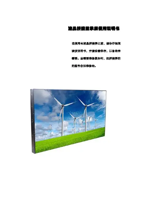
液晶拼接显示屏使用说明书在使用本液晶拼接屏之前,请你仔细阅读该说明书,并请妥善保存,以备将来需要。
当需要维修服务时,把拼接屏的的型号告诉维修站。
目录重要安全说明 (2)准备工作 (2)附件 (3)简介 (4)外部设备的安装 (4)整机外围接口示意图............................................................. 错误!未定义书签。
系统组成原理......................................................................... 错误!未定义书签。
大屏幕墙组成框图................................................................. 错误!未定义书签。
DVD的安装........................................................................... 错误!未定义书签。
连接S-Video线缆时 ............................................................. 错误!未定义书签。
Video设备的安装 (7)HDMI信号输入的安装 (7)PC的安装 (7)地址开关的设定 (8)外接控制设备的安装 (8)液晶拼接屏拼接软件控制系统(标准) (12)软件概述 (12)软件安装................................................................................. 错误!未定义书签。
运行环境........................................................................................... 错误!未定义书签。
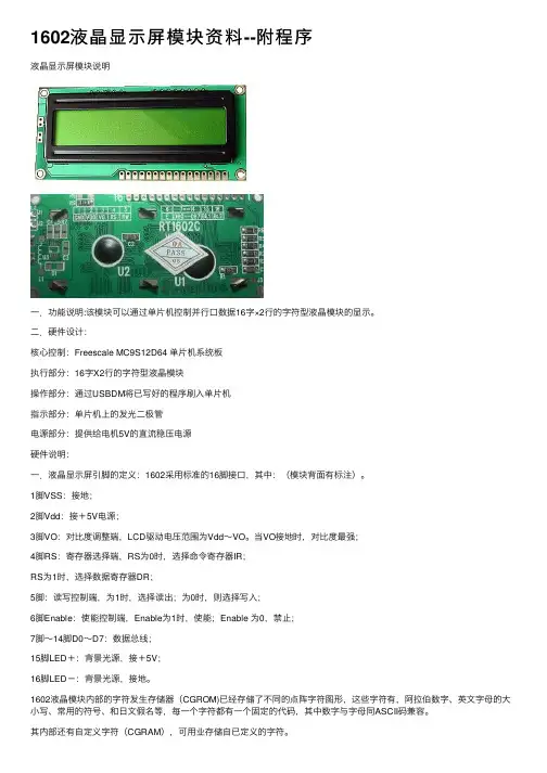
1602液晶显⽰屏模块资料--附程序液晶显⽰屏模块说明⼀.功能说明:该模块可以通过单⽚机控制并⾏⼝数据16字×2⾏的字符型液晶模块的显⽰。
⼆.硬件设计:核⼼控制:Freescale MC9S12D64 单⽚机系统板执⾏部分:16字X2⾏的字符型液晶模块操作部分:通过USBDM将已写好的程序刷⼊单⽚机指⽰部分:单⽚机上的发光⼆极管电源部分:提供给电机5V的直流稳压电源硬件说明:⼀.液晶显⽰屏引脚的定义:1602采⽤标准的16脚接⼝,其中:(模块背⾯有标注)。
1脚VSS:接地;2脚Vdd:接+5V电源;3脚VO:对⽐度调整端,LCD驱动电压范围为Vdd~VO。
当VO接地时,对⽐度最强;4脚RS:寄存器选择端,RS为0时,选择命令寄存器IR;RS为1时,选择数据寄存器DR;5脚:读写控制端,为1时,选择读出;为0时,则选择写⼊;6脚Enable:使能控制端,Enable为1时,使能;Enable 为0,禁⽌;7脚~14脚D0~D7:数据总线;15脚LED+:背景光源,接+5V;16脚LED-:背景光源,接地。
1602液晶模块内部的字符发⽣存储器(CGROM)已经存储了不同的点阵字符图形,这些字符有,阿拉伯数字、英⽂字母的⼤⼩写、常⽤的符号、和⽇⽂假名等,每⼀个字符都有⼀个固定的代码,其中数字与字母同ASCII码兼容。
其内部还有⾃定义字符(CGRAM),可⽤业存储⾃已定义的字符。
指令1:清显⽰屏;指令2:光标复位;指令3:光标和显⽰模式设置 I/D:光标移动⽅向,⾼电平右移,低电平左移,S:屏幕上所有⽂字是否左移或者右移。
⾼电平表⽰有效,低电平则⽆效。
指令4:显⽰开关控制。
D:控制整体显⽰的开与关,⾼电平表⽰开显⽰,低电平表⽰关显⽰ C:控制光标的开与关,⾼电平表⽰有光标,低电平表⽰⽆光标 B:控制光标是否闪烁,⾼电平闪烁,低电平不闪烁。
指令5:光标或显⽰移位 S/C:⾼电平时移动显⽰的⽂字,低电平时移动光标。
lcd1602流程图LCD1602流程图是指在液晶显示屏模块上显示特定信息的流程图。
下面我们将介绍一个简单的LCD1602流程图,包括初始化液晶模块、设置显示模式、输入要显示的内容等步骤。
首先,我们需要准备一个Arduino开发板和一个LCD1602模块。
将LCD模块的VCC和GND引脚分别连接到Arduino的3.3V和GND引脚上,将SDA和SCL引脚连接到Arduino的A4和A5引脚上。
然后,编写以下步骤来实现流程图。
第一步,初始化液晶模块。
在Arduino开发环境中,我们需要包含LiquidCrystal_I2C.h库文件,然后创建一个LiquidCrystal_I2C对象。
使用begin()函数初始化LCD模块,并设置显示模式和光标的闪烁。
第二步,设置显示模式。
使用setCursor()函数将光标移动到特定位置,并使用print()函数输入要显示的内容。
根据需要可以设置一到两行进行显示。
第三步,设置滚动显示。
使用scrollDisplayLeft()或scrollDisplayRight()函数在屏幕上滚动显示内容。
第四步,设置光标显示状态。
使用noCursor()函数关闭光标显示,使用cursor()函数开启光标显示。
第五步,设置光标闪烁状态。
使用noBlink()函数关闭光标闪烁,使用blink()函数开启光标闪烁。
第六步,设置显示打开/关闭状态。
使用noDisplay()函数关闭显示,使用display()函数开启显示。
第七步,设置自定义字符。
使用createChar()函数在CGRAM (字符生成RAM)中自定义字符,并使用write()函数在屏幕上显示。
第八步,清除屏幕。
使用clear()函数清除屏幕上的内容。
第九步,设置屏幕显示次数。
使用blinkDisplay()函数设置屏幕的显示次数,并使用count()函数检测屏幕的显示次数。
第十步,控制光标位置。
使用setCursor()函数将光标移动到特定位置。
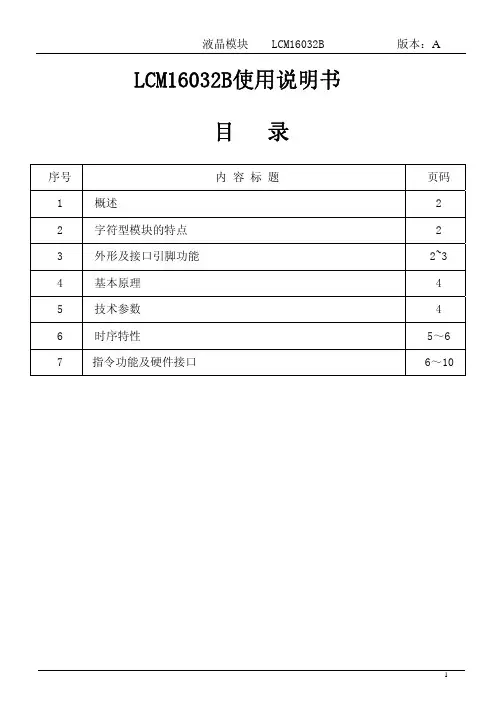
LCM16032B使用说明书目 录序号 内 容 标 题 页码1 概述 22 字符型模块的特点 23 外形及接口引脚功能 2~34 基本原理 45 技术参数 46 时序特性 5~67 指令功能及硬件接口 6~101.概述方便、带中文字库、显示清晰,广泛应用于各种人机交流面板。
LCM16032B 液晶显示模块是160×32 点阵的汉字图形型液晶显示模块,可显示汉字及 图形,内置8192 个中文汉字(16X16 点阵)、128 个字符(8X16 点阵)及 64X256点阵显示RAM (GDRAM )。
可与CPU 直接接口,提供两种界面来连接 微处理机:8-位并行及串行两种连接方式。
具有多种功能:光标显示、画 面移位、睡眠模式等。
1.1结构牢:带PCB、背光、铁框1.2 IC 采用矽创公司ST7920,功能强大,稳定性好1.3功耗低:10 - 100mW(不带背光10mW,带背光不大于100mW); 1.4显示内容:●160*32点阵单色图片;●内置8192 个中文汉字(16X16 点阵)、128 个字符(8X16 点阵)及64X256点阵显示RAM (GDRAM ).1.5指令功能强:可组合成各种输入、显示、移位方式以满足不同的要求;1.6接口简单方便:采用3线SPI 串行接口,可只需3位MPU 的端口。
也可选用8位并行接口。
1.7工作温度宽:-20℃ - 70℃;1.8可靠性高:寿命为50,000小时(25℃)。
3.外形尺寸及接口引脚功能图1.外形尺寸我司专注于液晶屏及液晶模块的研发、制造。
所生产LCM16032B型液晶模块由于使用2.LC M 16032B图像型点阵液晶模块的特性模块的接口引脚功能引脚 符 号 名 称 功 能1 VSS接地 0V2 VDD 电路电源 5V,或3.3V 可选3 V0 LCD V0电压输入 可以通过此脚对LCD 驱动电压进行调整4RS(CS*)寄存器选择信号(串行时为片选:CS)1. 并行接口时:1:数据寄存器 0:指令寄存器2. 串行接口时:片选信号,低电平有效5 R/W(SID*) 读写选择(串行时为串行数据:SID) 1.并行接口时:0: 写 1:读2.串行时为串行数据输入:SID 6E(SCLK*)读写使能信号(串行时为串行时钟:SCLK) 1. 并行接口时:读写使能信号 2. 串行时为串行时钟:SCLK 7~14 D0~D7数据DB0~DB7并行接口时:数据总线DB0~DB7 串行接口时:无效,空脚4位并行接口时,DB4~DB7作为数据总线,DB0~DB3不起作用15 PSB 并行/串行选择 1:选择并行,0:选择串行,也可在PCB 上与VDD(1)或VSS(0)连接达到选择并/串接口。
LCD驱动程序开发指南LCD驱动开发指引1、LCD驱动概述LCD驱动程序调试,是整个⼿机研发过程中⾮常重要的⼀个环节,在每个新的机型开发的初期,最先都要调试LCD驱动程序,我们俗称“点屏”。
“点屏”的调试包括两个部分,⼀是点亮LCD的背光,⼆是调试LCD显⽰。
背光驱动调试的⽅法与技巧,会在背光⽂档中叙述,暂不在这篇⽂档⾥讨论,本⽂将重点讨论LCD的电路原理、驱动程序分析、LCD驱动调试经验总结和具体驱动调试案例的分析。
2、LCD原理及电路分析相关概念:LCD:全称是Liquid Crystal Display 液晶显⽰屏LCM:全称是Liquid Crystal Module指的是液晶显术模块,包括液晶屏及液晶的外围FPC电路和结构件。
LCD的FPC电路:指LCM模块中的液晶外围电路,这部分电路由LCD模组⼚家按照我们对LCD的接⼝要求进⾏设计的。
在LCD驱动调试中,看FPC电路图也是很重要的⼀个环节。
LCD外围电路:我们通常也简称为LCD电路,指的是baseband端的LCD接⼝电路部分,这部分电路由我们⾃⾏设计。
LCD模组⼚家:指信利,天马,京东⽅这些⼚家。
他们将LCD制作成可以供我们⽣产使⽤的LCM模组。
2.1LCD芯⽚介绍⽬前⼿机使⽤的⼤部分显⽰器件都是LCD(Liguid Crystal Display)器件,⽬前康佳使⽤的LCM模块由信利、京东⽅、天马、凌达这⼏家⼚商供货。
但是LCM⽣产⼚家对我们调试驱动并没有任何关系,我们需要了解的是LCM所使⽤的IC型号。
因为,我们实际上是对LCD的IC进⾏编程,间接控制LCD⾯板,常⽤的IC有HD66773、S6B33B2/ S6B33B6、HD66777等。
LCD驱动的编程,除了要关注IC的型号,还要关注LCD FPC的电路设计,LCD外围电路设计,基带芯⽚的LCD接⼝单元,背光IC的控制等⼏个⽅⾯,当然也包括软件的上层程序。
下⾯我们就先了解⼀下LCD IC的内部结构,这是编程要关注的最主要⽅⾯。
LCD12864系列点阵型液晶显示模块使用说明书一、OCM12864液晶显示模块概述1.OCM12864液晶显示模块是128×64点阵型液晶显示模块,可显示各种字符及图形,可与CPU直接接口,具有8位标准数据总线、6条控制线及电源线。
采用KS0107控制IC。
2.外观尺寸:113×65×11mm(ocm12864-1), 93×70×10mm(ocm12864-2)78×70×10mm(ocm12864-3),3.视域尺寸:×38.8mm(ocm12864-1) ×38mm(ocm12864-2),64×44mm(ocm12864-3)4.<5.重量:大约g补充说明:外观尺寸可根据用户的要求进行适度调整。
二、最大工作范围1、逻辑工作电压(Vcc):~2、电源地(GND):0V3、LCD驱动电压(Vee):0~-10V4、输入电压:Vee~Vdd5、工作温度(Ta):0~55℃(常温) / -20~70℃(宽温)}6、保存温度(Tstg):-10~65℃三、电气特性(测试条件 Ta=25,Vdd=+/1、输入高电平(Vih):2、输入低电平(Vil):3、输出高电平(Voh):4、输出低电平(Vol):5、工作电流:四、接口说明—12864-3A接口说明表管脚号管脚电平说明1CSA H/L]片选择信号,低电平时选择前64列。
2CSB H片选择信号,低电平时选择后64列。
3GND0V【逻辑电源地。
4VCC5V逻辑电源。
5VEE-10V'LCD驱动电源。
6D/I H/L数据\指令选择,高电平:数据D0-D7将送入显示RAM;低电平:数据D0-D7将送入指令寄存器执行。
7R/W%读\写选择,高电平:读数据;低电平:写数据。
H/L8E L读写使能,高电平有效,下降沿锁定数据。
D7-D0位数据为1表示显示,数据为0表示不显示。
HS12864-18液晶显示模块使用说明书感谢您关注和使用我们的液晶产品。
如果您在使用中有任何疑问,请拨打我们的客户服务热线寻求技术支持和获取相关资料,我们竭诚为您服务。
您可以登录我们的网站了解最新产品信息。
或者您可以在我公司网站的留言簿栏目留下您宝贵的意见。
深圳汉昇实业有限公司SHENZHEN HANSHENG INDUSTRIAL CO.,LTD地址:深圳市南山区西丽镇官龙工业村东区18栋5楼邮编:518055公司主页:联系电话:传真:一、 概述HS12864-18使用KS0108(或其兼容芯片)作为控制器,适配M6800系列时序,具有8位标准数据总线。
可显示各种字符及图形。
每个KS0108拥有64×64位(512字节)的显示RAM,HS12864-18显示屏上的64×64点,显示RAM中的数据直接作为显示驱动信号。
HS12864-18具有操作指令简单,低功耗的特点。
HS12864-18采用COB工艺制作。
二、 外形结构1. 外形图2. 主要外形尺寸项 目 标 准 尺 寸 单 位模 块 体 积 75.0×54.7×12.5(max) mm视 域 60.0×32.6 mm行 列 点 阵 数 128×64 dots点 距 离 0.43×0.43 mm点 大 小 0.40×0.40 mm三、 硬件说明1. 接口定义管脚符号电平功能描述1 VDD 5.0V 供电电源,5.0V2 VSS 0V 电源地3 V0 负压 LCD驱动电压输入端(对比度调节)4-11 DB0~DB7H/L 数据线12 CS1 L 片选信号1,低有效,对应左半屏64×64点13 CS2 L 片选信号2,低有效,对应右半屏64×64点14 /RST H/L 复位信号,低有效15 R/W H/L 读/写信号高:读操作低:写操作16 RS H/L 寄存器选择端高:数据寄存器低:命令寄存器17 E H,H->L 使能信号18 V out 负压负压输出端19 LEDA 5.0V 背光正极20 LEDK 0V 背光负极2. 最大工作范围(1)逻辑工作电压(Vdd):4.5~5.5V(2)电源地(VSS): 0V(3)工作温度(Ta): -20~70℃(宽温)(4)存储温度(Tstg): -30~80℃3. 电气特性(测试条件 Ta=25,Vdd=5.0+/-0.25V)(1)输入高电平(Vih): 3.5Vmin(2)输入低电平(Vil): 0.55Vmax(3)输出高电平(Voh): 3.75Vmin(4)输出低电平(Vol): 1.0Vmax(5)工作电流: 8.0mAmax (注:不含背光电流)4. 原理简图VSS V0CS1CS25. HS12864-18的对比度调节HS12864-18上有负压电路,生成的负压由Vout 脚输出,加过用户主板返回到液晶模块接口的V0端,由此调节对比度。
液晶显示模块使用手册 FM FM12832D 12832D台 湾 (重庆市) 汇 福 电子有限公司网 站: 邮 件: cqs.hf cqs.hf@@ cqshf cqshf@@ 电 话话: 023023023--6380 0611 6353 72396380 0611 6353 7239 传 真真: 023023023--6353 7239 6353 7239手 机: 139****7064/131****5453联系人联系人:: 王王 强 ( (先生先生先生) / ) / ) / 李李 培 英 ( (小姐小姐小姐)) 地址地址::重庆市重庆市渝中区中山三路渝中区中山三路86号重百电子城二楼1818--2号 地址地址::重庆市渝中区新华路220号B2楼实田电子城18区1919--20号台 湾 (重庆市) 汇 福 电子有限公司网 站: 邮 件: cqs.hf cqs.hf@@ cqshf cqshf@@ 电 话话: 023023023--6380 0611 6353 72396380 0611 6353 7239 传 真真: 023023023--6353 7239 6353 7239手 机: 139****7064/131****5453联系人联系人:: 王王 强 ( (先生先生先生) / ) / ) / 李李 培 英 ( (小姐小姐小姐)) 地址地址::重庆市渝中区中山三路86号重百电子城二楼1818--2号 地址地址::重庆市渝中区新华路220号B2楼实田电子城18区1919--20号目 录录(一)概述 (1)(二) 外形尺寸图 (1)(三) 模块主要硬件构成说明 (2)(四) 模块的外部接口 (3)(五) 指令说明 (4)(六) 读写操作时序 (6)(七) 应用举例 (7)概述一.概述FM12832是一种图形点阵液晶显示器,它主要由行驱动器/列驱动器及128×32全点阵液晶显示器组成。
产品类型: 字符型LCD液晶显示模组产品型号: 1602A客户:客户编号:日期:确认(盖章)制造商客户目录1.修订记录2.概述3.外形尺寸4.硬件方框图5.电气特性6.接口说明7.指令说明8.操作时序说明9.应用例程10.注意事项1 . 修订记录版本发行日期新制/修订内容 V1.0 2020-8-12新制2.概述1602A 字符型液晶显示模块是专门用于显示字母、数字元、符号等的点阵型液晶显示模块。
分4 位和8 位数据传输方式。
提供5×7 点阵+光标的显示模式。
提供显示数据缓冲区DDRAM、字符发生器CGROM 和字符发生器CGRAM,可以使用CGRAM 来存储自己定义的最多8 个5×8 点阵的图形字符的字模数据。
提供了丰富的指令设置:清显示;光标回原点;显示开/关;光标开/关;显示字符闪烁;游标移位;显示移位元等。
提供内部上电自动复位电路,当外加电源时,自动对模块进行初始化操作,将模块设置为默认的显示工作状态。
显示字符数: 16 字符 X 2 行字符点阵:5X7字阵+光标显示颜色及背光颜色: STN 蓝,黄绿,灰; 背光黑,白,黄绿偏光膜:全透/半透观察角度: 6:00显示占空比: 1/16驱动偏压: 1/5控制芯片:SPLC780D或兼容IC(如AIP31066)字符发生器 ROM (CGROM): 10880 bits (192 character 5*8 dots) 或(64character 5*11 dots)字符发生器 RAM (CGRAM): 64X8 bits (8 characters 5*8 dots)或(4 characters 5*11 dots)显示数据 RAM (DDRAM) :80X8 bits (80 characters max)尺寸 (Unit: mm)外形尺寸: 80X36X11可视区域 : 64.5X13.8字符字体: 5X7 dots + 光标字符尺寸:55.7X11点尺寸:0.54X0.6字符间距: 3.52X5.85重量:g 对比度:V0外部调节或内部固定对比度工作电压: +3.3V或+5V 默认5V3.外形尺寸:4.硬件方框图:5.电气特性5.1极限参数5.2.1 直流参数1(Ta=25o C,Vdd=4.5V~5.5V)5.2.2 直流参数2(Ta=25o C,Vdd=2.7V~4.5V)典型值参数名称符号条件最小值最大值单位电源电压Vdd -0.37.0VLCD 驱动电压V5Vdd-10.0Vdd+0.3V 输入电压Vi -0.3Vdd+0.3V 工作温度(T)Top --2070℃储存温度(T)Tstg--3080℃标称值参数名称符号条件最小典型最大单位电源电压Vdd-GND - 4.5 5.0 5.5V 工作电流(不包括背光)Idd 0.9 1.5 1.7mA LCD 驱动电流Iee -0.6-mA LCD 驱动电压Vdd-V5Vdd=5V4.2 4.5 4.8V LED 背光工作电流If 171820mA LED 背光功耗Pd Vf=3.0~3.2V90100110mW 输入高电平Vih 2.5-Vdd V 输入低电平Vil -0.3-0.6V 输出高电平Voh Ioh=-0.205mA 2.4--V 输出低电平VolIo1=1.2mA--0.4V标称值参数名称符号条件最小典型最大单位电源电压Vdd-GND - 2.7 3.3 4.5V 工作电流(不包括背光)Idd 0.450.9 1.0mA LCD 驱动电流Iee -0.6-mA LCD 驱动电压Vdd-V5Vdd=3.3V4.2 4.5 4.8V LED 背光工作电流If 171820mA LED 背光功耗Pd Vf=3.0~3.2V556066mW 输入高电平Vih 0.7Vdd -Vdd V 输入低电平Vil -0.3-0.55V 输出高电平Voh Ioh=-0.1mA 0.75Vdd--V 输出低电平VolIol=0.1mA--0.2VddV液晶显示模块使用说明书5.3.1 交流参数1(Ta=25o C,Vdd=4.5V~5.5V)5.3.2 交流参数2(Ta=25o C,Vdd=2.7V~4.5V)交流测试波形图写模式读模式6.接口说明脚号符号功能备注1Vss 0V 2Vdd +5V3Vo 电源供应LCD 偏压调节对比度调节4RS 数据/指令选择(H:数据 L: 指令)5R/W 读/写选择(H:读 L:写)6E 使能信号7DB0数据位 08DB1数据位19DB2数据位210DB3数据位311DB4数据位412DB5数据位513DB6数据位614DB7数据位715A LED 背光正16KLED 背光负7.指令说明模块具有4位/8位MCU 并行通讯模式,4位/8位总线通过指令寄存器的DL 位进行选定。
液晶显示模块开基本步骤
————————————————————————————————作者:————————————————————————————————日期:
核心器件: SG12864-5C
SG12864-5C是采用三星电子公司生产的KS0713为内显示控制芯片的小型液晶显示模块。
该128×64点阵液晶显示模块具有二种不同功耗模式,价格低,数据可读可写,使用方便等优点。
其所采用的KS0713更是一种小型的大规模集成并带有驱动器的点阵型液晶控制芯片。
KS0713体积小,外观尺寸只有42mm×39mm,29个引脚;可直接由微处理器控制;数据读写操作不受外部时钟控制;集成化程度高,自带液晶所必需的电源驱动。
图1 ADC倒转列地址和显示列地址之间的对应关系示意图
液晶显示模块开发的基本步骤
点阵型液晶显示模块的开发基本可以分为三步:
根据开发系统的要求完成单片机与液晶显示模块的接口,通常的接口有总线模式和I/O模式两种。
特别要注意,液晶显示模块对负电压的要求,如果负电压值不符合要求,则会造成液晶屏显示一片全黑,或是对比度太低。
根据控制器的时序图和寄存器的命令表格,通过编写程序往显存的指定地址送一个字节,比如0xFF,只要液晶上显示一条实线线段,如果可以正常启动并有数据显示,无论数据显示的对错甚至显示的是乱码,都表明液晶模块的初始化已经完成,数据传输通道已经基本打通。
仔细研究显存的排列方式/数据的传输方式是纵向还是横向,字节内的位顺序是左高右低,还是左低右高,1是对应黑点还是白点,显存地址是怎样排列的,是自动加1,还是要另外设置等等。
SG12864-5C液晶显示模块中采用的KS0713显示控制芯片
SG12864-5C(128×64点阵式LCD)液晶显示模块在悬空背光源管脚的状态下,其电流最大值仅为0.25mA,通常典型电流值为0.17mA,输入电压为3V~3.6V。
满足了绝大部分嵌入
式系统对低功耗液晶显示的要求。
模块所采用的KS0713控制器直接接收8位并行数据,在显示的同时将数据存储在模块内的数据存储器中(DDRAM)。
控制芯片KS0713的初始化
KS0713初始化的基本步骤和其它同类控制芯片的初始化基本相同。
值得开发人员特别注意的是:KS0713内部的ADC,SHL定义了数据逐行、逐列显示的逐次顺序,其关系顺序如表1所示。
基于TI(德州仪器)公司的16位微处理器MSP430F149在C语言开发环境下对KS0713的初始化:
void Init_LCD(void) //定义初始化函数
{ P6OUT &=~RESET;//复位位置零
Delay(500);
P6OUT |= RESET; //复位位置位
Delay(5);
P6OUT &=~CS;//片选位置零
Send_Command(0xE2);//复位指令
Send_Command(0xA1);//ADC指令(ADC=1)数据传输SEG132~SEG1,液晶屏幕显示SEG1~SEG132
Send_Command(0xC0);//SHL指令(SHL=0)传输,显示COM1~COM64
Send_Command(0xA3);//设定LCD占空比为1/9
Send_Command(0x2F);//设定电源控制
Send_Command(0x26);//调节寄存器选择
Send_Command(0x81);//设定参考电压模式
Send_Command(0x1C);//设定参考电压寄存器
Send_Command(0x40);//设定显示行(COM1)
Send_Command(0xAF); }//等待显示开始
显示数据存储器
DDRAM用来存放液晶的显示数据,它是一个65行.132列的地址空间。
65行构成了9页,其中前8页由8列构成(DB0~DB7),第9页是单独的一行(只有DB0)。
显示数据DB0~DB7直接通过MCU的数据口送入,并通过DB0~DB7直接读写到对应的8行。
同时每一个点阵可以通过确定行地址和列地址来确定位置。
显示数据的起始位置
由于KS0713的地址空间是65×132的,实际在控制LCD时,由于只用到64×128的地址空间,就存在着起始地址的问题。
数据并行传输之后始终是从DB0(第一行)开始显示。
而列地址则不同。
内部地址对应的方式不同则会导致起始数据列地址的不同。
如果LCD的第0列地址和KS0713的第0列地址相对应,则相应的起始列地址为0x00;如果LCD的第0列地址和KS0713的第1列地址相对应,则相应的起始列地址为0x01;以此类推。
通过实验发现SG1 2864-5C液晶显示模块,其内部LCD的第0列地址实际上和KS0713的第4列地址相对应,而与其所提供的通用汇编演示程序:MOV A,#02;的列起始地址有出入,而且原文件中也未对其所举范例中列地址为何从#02开始做出明确的解释。
实际以此液晶显示模块显示传输的并行数据的起始列地址应为#04。
字模点阵数据的提取和传输
SG12864-5C的逐行、逐列显示顺序可以根据用户的不同要求在初始化时加以设置。
通过使用SG12864-5C,发现KS0713控制芯片向LCD送数据的方式也和人们通常习惯的横向数据传输方式不同,采用的是竖向数据传输方式:对于64行128列的LCD,先送第1列,第0行~第7行的数据;第2列,第0行~第7行的数据;第3列,第0行~第7行的数据;直到第128列,第0行~第7行的数据。
再送第1列,第8行~第15行的数据;第2列,第8行~第15行的数据;最终第128列,第56行~第63行的数据。
ADC选择指令可倒转列地址和显示列地址之间的对应关系,如图1所示。
因而,要求送数据格式为:先送第1列,第7行~第0行的数据;第2列,第7行~第0行的数据;第3列,第7行~第0行的数据;第1列,第15行~第8行的数据;第2列,第15行~第8行的数据;第128列,第63行~第56行的数据。
由此,对于字模的提取,KS0713也就有了特殊的要求:为了能够在LCD上显示出图2(a)的图形,我们必须先将图2(a)横向左右调换得到图2(b),再将图2(b)沿纵向上下调换得到图2 (c)。
最终传输以图2(c)的格式所提取字模数据,才可以得到图2(a)的显示。
(a)(b) (c)
图2 KS0713字模提取示意图
对于在初始化之下采用功能不完善的字模提取软件,在取得“纵向8点左高位”输出格式的数据时,可以参考图1,利用表2手工提取字模。
结语
本文介绍了采用KS0713控制芯片的SG12864-5C液晶显示模块的应用,详细介绍了控制芯片KS0713在使用时应注意的问题,并提出了直观的技巧性的解决方法。
<。