五相步进电机驱动电路开发(论文翻译)_图文(精)
- 格式:doc
- 大小:2.36 MB
- 文档页数:44
五相步进电机实验概述五相步进电机是一种常用的电动机,具有高精度、低噪音、快速响应等特点,被广泛应用于机器人、精密仪器、通讯设备、医疗器械等领域。
在五相步进电机的驱动控制方面,实验验证是必不可少的环节。
本文以五相步进电机实验为出发点,介绍了五相步进电机的基本原理、实验装置、实验步骤以及实验结果分析等内容。
1. 基本原理五相步进电机是一种将交流电信号转换为直流电信号的电机,其工作原理是通过五组电磁线圈的电流变化来实现转动。
五相步进电机的运行分为两种模式:全步进模式和半步进模式。
在全步进模式下,最小步长角度为1.8度,即转一圈需要200个步进信号;而在半步进模式下,最小步长角度为0.9度,即转一圈需要400个步进信号。
五相步进电机的步进运动是通过一个称为步进驱动器的设备来实现的。
2. 实验装置五相步进电机实验的主要装置有五相步进电机、步进驱动器、控制电路板、程序设计器以及计算机等。
步进电机是由五组电磁线圈组成的,每个线圈都可以独立控制。
步进驱动器用于控制电流的变化,从而实现步进运动。
控制电路板用于将计算机上的命令转换成相应的电流信号,并通过步进驱动器传输给步进电机。
程序设计器则用于编程控制步进电机的转动角度和步长等参数。
计算机是整个实验装置的核心,通过计算机可以实现对步进电机的实时监控和控制。
3. 实验步骤(1)连接电路。
首先,将五相步进电机、步进驱动器、控制电路板和计算机连接起来,并进行相应的设置。
(2)编写控制程序。
使用编程语言编写相应的控制程序,包括控制步进电机转动的角度和步长等参数。
(3)运行程序并实时监控。
将编写好的程序上传至程序设计器,然后运行程序,并实时监控五相步进电机的运动状态。
(4)分析实验结果。
根据实际运行情况,对实验结果进行分析和比较,评估该设备的性能和可靠性。
4. 实验结果分析通过五相步进电机实验,我们可以对该设备的转动速度、精度和稳定性等方面进行评估和分析。
实验结果表明,五相步进电机具有转动稳定性好、响应速度快等优点,适用于需要精准控制转动角度和步长的应用场景。
About stepper motor and drive systemStep characteristics for machine for angular displacement for entering the electrical engineering is first kind will give or get an electric shocking the pulse signal conversion cowgirl or line potential moving battery carry outing a piece, having the fast stopping, accurate step entering and directly accepting the arithmetic figure measuring, because of but got the extensive application.Such as in the drafting machine, print the machine and optical instrument inside, and all adopt the inside of a place control system for entering the electrical engineering to positioning to paint the pen print head or optical prinipal, especially indrstry process the type control, and move to spread to feel the to can immediately attain the precision fixed position because of its precision and need not potential, and control the technique along with the calculator of continuously deveolp, applied to would be more and more extensive.Control and can is divided into the simple control sum the complicacy to control to motor two kind.The simple control points to proceeds to start to motor, the system move, positive and negative revolution and sequential plicacy the control point to the motor's revolving speed, screw angle, turning moment, tension, electric current etc. physics quantisty progress control.Control technique that the development that motor get force is in latest development achievement that micro-electronics technique, electric power electronics, spread to feel the the technique, automatic control the technique, tiny machine the application technique to wait.Exactly the advance of these techniques make the motor control the technique at near two 10-year insides change for turn overing the ground of day is take placed.Among them the motor's control division have already been controled by emulation gradually let locate to regard single flake machine as principle of microprocessor control, formation the mix control system of the arithmetic figure and emulation and the application of the pure arithmetic figure control system, combine control the direction to total amount word to quickly deveolp.The motor's drive part of power forusing the piece experienced a few renewals to change the on behalf, current switch speed sooner, more simple whole type power piece of control the MOSFET become the main current with IGBT.Stepper motors have the following benefits:•Low cost•Ruggedness•Simplicity in construction•High reliability•No maintenance•Wide acceptance•No tweaking to stabilize•No feedback components are needed•They work in just about any environment•Inherently more failsafe than servo motors.There is virtually no conceivable failure within the stepper drive module that could cause the motor to run away. Stepper motors are simple to drive and control in an open-loop configuration. They only require four leads. They provide excellent torque at low speeds, up to 5 times the continuous torque of a brush motor of the same frame size or double the torque of the equivalent brushless motor. This often eliminates the need for a gearbox. A stepper-driven-system is inherently stiff, with known limits to the dynamic position error.Stepper Motor DisadvantagesStepper motors have the following disadvantages:•Resonance effects and relatively long settlingtimes•Rough performance at low speed unless amicrostep drive is used•Liability to undetected position loss as a result ofoperating open-loop•They consume current regardless of loadconditions and therefore tend to run hot•Losses at speed are relatively high and can causeexcessive heating, and they are frequently noisy(especially at high speeds).•They can exhibit lag-lead oscillation, which isdifficult to damp. There is a limit to their availablesize, and positioning accuracy relies on themechanics (e.g., ballscrew accuracy). Many ofthese drawbacks can be overcome by the use ofa closed-loop control scheme.Note: The Compumotor Zeta Series minimizes orreduces many of these different stepper motor disadvantages.There are three main stepper motor types:•Permanent Magnet (P.M.) Motors•Variable Reluctance (V.R.) Motors•Hybrid MotorsWhen the motor is driven in its full-step mode, energizing two windings or “phases”at a time (see Fig. 1.8), the torque available on each step will be the same (subject to very small variations in the motor and drive characteristics). In the half-step mode, we are alternately energizing two phases and then only one as shown in Fig. 1.9. Assuming the drive delivers the same winding current in each case, this will cause greater torque to be produced when there are two windings energized. In other words, alternate steps will be strong and weak. This does not represent a major deterrent to motor performance—the available torque is obviously limited by the weaker step, but there will be a significant improvement in low-speed smoothness over the full-step mode.Applications in hazardous environmentsor in a vacuum may not be able to use a brushed motor. Either a stepper or a brushless motor is called for, depending on the demands of the load. Bear in mind that heat dissipation may be a problem in a vacuum when the loads are excessive.continuous duty applications suit the servo motor, and in fact a step motor should be avoided in such applications because the high-speed losses can cause excessive motor heating.are the natural domain of the stepper due to its high torque at low speeds, good torque-to-inertia ratio and lack of commutation problems.The brushes of the DC motor can limit its potential for frequent starts, stops and direction changes.continuous duty applications are appropriate to the step motor. At low speeds it is very efficient in terms of torque output relative to both size and input power. Microstepping can be used to improve smoothness in lowspeed applications such as a metering pump drive for very accurate flow control.Stepper motor is a stepper motor for precise electrical and mechanical actuators, which are widely used in industrial machinery, digital control, for the system reliability, interoperability, maintainability, and cost-optimal, according to the control system functional requirements and Control system through the microcontroller memory, I/O interface, interrupt, keyboard, LED display of the expansion of the annular distributor stepping motor, drive and protection circuit, man-machine interface circuit, interrupt system and reset circuit, a single voltage drive circuit, etc.designed to achieve a four-phase stepper motor rotating, and emergency stop functions.To achieve the stepping motor system in NC Machine Tools, system design, two external interrupts, in order to achieve within a certain period of time stepper motor repeated Reversible function, ie, the turret CNC automatic feed movement. With the continuous development of single chip microcomputer, microcontroller in household electronic products widely applied, since the since the early sixties, the stepper motor applications are greatly enhanced.People use it to drive the clock and other instruments with pointers, printers, plotters, disk CD-ROM drive, a variety of automatic control valves, various tools, as well as robots and other mechanical devices.In addition,as the acIn addition, as the actuator, stepper motor is one of mechanical and electrical integration of the key products are widely used in a variety of automatic control systems, microelectronics and computer technology with the development of its requirements with the Japanese fear of growing in all the field of application of the national economy has. Stepper motor digital control system of electromechanical actuators commonly used, due to its high precision, small size, flexible to control, so the smart meter and position control hasbeen widely used in large-scale integrated circuits technology development, and SCM The increasing popularity of design features, the lowest price of the stepper motor control driver provides advanced technology and adequate resources.步进电机及其驱动系统简介步进电机是一种将电脉冲信号转换成相应的角位移或线位移的机电执行元件,具有快速启停、精确步进以及直接接受数字量的特点,因而得到了广泛的应用。
摘要着重对步进电动机的PLC控制系统作了研究。
步进电动机的拍数控制采用步进指令,实现五相步进控制的独立模块,按照指令执行相应的模块即可。
正反转控制是用一个输出继电器实现输出脉冲顺序的控制。
速度的控制就是对输出脉冲时间的控制,本设计用时间继电器指令、数据加减1指令、数据比较指令、位数据传输指令等实现了它的控制。
采用PLC控制步进电动机可以用很低的成本实现很复杂的控制方案,而且由于PLC编程的灵活性,使修改控制方案成为轻而易举的事情,只要重新编程序即可。
关键词:步进电机可编程序控制器五项步进引言可编程序控制器简称为PLC,它出现于20世纪60年代,随着PLC的迅速发展,它的性能越来越高,价格越来越便宜。
因此就有可能比较普遍地应用PLC来控制各类电机,完成各种新颖的、高性能的控制策略,使电机的各种潜在能力得到充分的发挥,使电机的性能更符合使用要求,还可以制造出各种便于控制的新型电机,使电机出现新的面貌。
近10年来,随着PLC价格的不断降低和用户需求的不断扩大,越来越多的中小设备开始采用PLC进行控制,PLC在我国的应用增长十分迅速。
随着中国经济的高速发展和基础自动化水平的不断提高,今后一段时期内PLC在我国仍将保持高速增长势头。
通用PLC应用于专用设备时可以认为它就是一个嵌入式控制器,但PLC 相对一般嵌入式控制器而方具有更高的可靠性和更好的稳定性。
实际工作中碰到的一些用户原来采用嵌入式控制器,现在正逐步用通用PLC或定制PLC 取代嵌入式控制器。
第一章绪论步进电机的控制系统由可编程控制器、环行脉冲分配器和步进电机功率驱动器组成,控制系统中PLC用来产生控制脉冲;通过PLC编程输出一定数量的方波脉冲,控制步进电机的转角进而控制伺服机构的进给量;同时通过编程控制脉冲频率一一既伺服机构的进给速度;环行脉冲分配器将可编程控制器输出的控制脉冲按步进电机的通电顺序分配到相应的绕组。
plc控制的步进电机可以采用软件环行分配器,也可以采用如图1所示的硬件环行分配器。
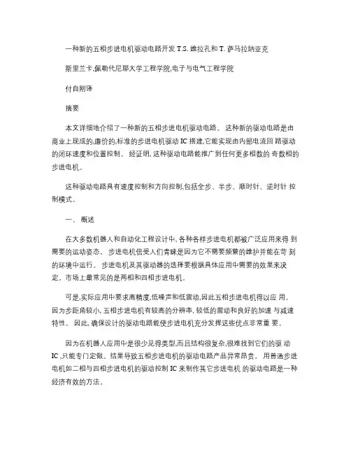
一种新的五相步进电机驱动电路开发 T.S. 维拉孔和 T. 萨马拉纳亚克斯里兰卡,佩勒代尼耶大学工程学院,电子与电气工程学院付自刚译摘要本文详细地介绍了一种新的五相步进电机驱动电路。
这种新的驱动电路是由商业上现成的,廉价的,标准的步进电机驱动 IC 搭建,它能实现由内部电流回路驱动的闭环速度和位置控制。
经证明, 这种驱动电路能推广到任何更多相数的奇数相的步进电机。
这种驱动电路具有速度控制和方向控制,包括全步、半步、顺时针、逆时针控制模式。
一、概述在大多数机器人和自动化工程设计中, 各种各样步进电机都被广泛应用来得到需要的运动姿态。
步进电机倍受人们青睐是因为它不需要频繁的维护并能在苛刻的环境中运行。
步进电机及其驱动器的选择要根据具体应用中需要的效果来决定。
市场上最常见的是两相和四相步进电机。
可是,实际应用中要求高精度,低噪声和低震动,因此五相步进电机得以应用。
因为步距角较小, 五相步进电机有较高的分辨率, 较低的震动和良好的加速与减速特性。
因此, 确保设计的驱动电路能使步进电机充分发挥这些优点非常重要。
因为在机器人应用中是很少见得类型,而且结构很复杂,很难找到它们的驱动IC ,只能专门定做。
结果导致五相步进电机的驱动电路产品异常昂贵。
用普通步进电机如二相与四相步进电机的驱动控制 IC 来制作其它步进电机的驱动电路是一种经济有效的方法。
L297继承了控制单极性和双极性步进电机所需要的所有控制电路系统。
L298N 双 H 桥驱动器形成了一个完善的步进电机微处理器接口。
在这里,我们通过给 L297和 L298N 加上微处理器和逻辑控制系统研究开发出了一种新的五相步进电机驱动电路。
第二部分解释了元器件特性。
第三部分介绍了控制逻辑电路设计。
第四部分是接口设计,结果在第五部分。
最后,第六部分加以总结。
二、主要元器件特性分析如图一所示,集成块 L297可以与 H 桥集成电路一起使用作为步进电机驱动器。
在该设计中, H 桥的功能用 L298N 或者 L293E 实现。
步进电机的构造(以5相步进为例)
步进电机的构造主要采纳图示的方式进行讲解:步进电动机构造上大致分为定子与转子两部分。
转子由转子1、转子2、永久磁钢等3 部分构成。
而且转子朝轴方向已经磁化,转子 1 为N 极时,转子2 则为S 极。
定子拥有小齿状的磁极,共有10个,皆绕有线圈。
其线圈的对角位置的磁极相互连接着,电流流通后,线圈即会被磁化成同一极性。
(例如某一线圈经由电流的流通后,对角线的磁极将同化成S 极或N 极。
)对角线的2个磁极形成1个相,而由于有A 相至E相等5个相位,因此称为5 相步进电动机。
系统构成图示转子的外圈由50个小齿构成,转子1 和转子2 的小齿于构造上互相错开1/2 螺距。
由此转子形成了100个小齿。
目前已经有转子单个加工至100齿的高辨别率型,那么高辨别率型的转子就有200个小齿。
因此其机械上就可以实现一般步进电机半步(一般步进电机半步需要电气细分达到)的辨别率。
电动机构造图2∶与转轴成垂直方向的断面图
1。
五相十拍步进电动机控制程序的设计与调试1.任务描述五相步进电动机有五个绕组:A、B、C、D、E正转顺序:ABC BC BCD CD CDEDE DEA EA EAB AB反转顺序:ABC BC BCD CD CDEDE DEA EA EAB AB2.控制要求用五个开关控制其工作:1号开关控制其运行(启/停)。
2号开关控制其低速运行(转过一个步距角需0.5S)。
3号开关控制其中速运行(转过一个步距角需0.1S)。
4号开关控制其高速运行(转过一个步距角需0.03S)。
5号开关控制其转向(ON为正转,OFF为反转)备注:调试时,一定要使时间大一些。
0.03秒太小了。
会使继电器输出类型的PLC 损坏。
3.程序设计的基本思路在进行程序设计时,首先应明确对象的具体控制要求。
由于CPU对程序的串行扫描工作方式,会造成输入输出的滞后,而由扫描方式引起的滞后时间,最长可达两个扫描周期,程序越长,这种滞后越明显,则控制精度就越低。
因此,在实现控制要求的基础上,应使程序尽量简洁﹑紧凑。
另一方面,同一控制对象,根据生产的工艺流程不同,控制要求或控制时序会发生变化,此时,要求程序修改方便、简单,即要求程序有较好的柔性。
以SIMATIC移位指令为步进控制的主体进行程序设计,可较好的满足上述设计要求。
功能要求对五相十拍步进电机的控制,主要分为两个方面:五相绕组的接通与断开顺序控制。
正转顺序:ABC→BC→BCD→CD→CDE→DE→DEA→EA→EAB→AB反转顺序:ABC←BC←BCD←CD←CDE←DE←DEA←EA←EAB←AB以及每个步距角的行进速度。
围绕这两个主要方面,可提出具体的控制要求如下:(1)可正转或反转;(2)运行前可以设置正转或者是反转;(3)步进三种速度可分为高速(0.05S),中速(0.3S),低速(0.5S)三档,并可随时手控变速;4.性能要求在实现控制要求的基础上,应使程序尽量简洁﹑紧凑。
另一方面,同一控制对象,根据生产的工艺流程不同,控制要求或控制时序会发生变化,此时,要求程序修改方便、简单,即要求程序有较好的柔性。
第3卷第2期2004年4月 江南大学学报(自然科学版)Journal of Southern Yangtze U niversity(N atural Science Edition) V ol.3 N o.2Apr. 2004 文章编号:1671-7147(2004)02-0160-04 收稿日期:2003-09-04; 修订日期:2004-02-13. 作者简介:刁红泉(1979-),男,江苏如东人,控制理论与控制工程专业硕士研究生.颜钢锋(1959-),男,浙江永康人,教授,硕士生导师.主要从事纺织C AD/C AM 、非线性系统等研究.基于单片机的通用型五相混合式步进电机驱动器设计刁红泉, 颜钢锋(浙江大学电气工程学院,浙江杭州310027)摘 要:分析了电脑绣花机系统中,现有的五相混合式步进电机驱动器存在低频转矩振荡、高频输出转矩不足和多电源供电及不通用等诸多不足之处的基础上,设计出一种基于单片机的通用型五相混合式步进电机驱动器.该驱动器使用单一电源供电,驱动五相电机时采用三相励磁PW M 输出方式,改善了驱动的矩频特性;同时,此驱动器在不脉冲细分的情形下,可以驱动二、三、四相步进电机。
此设计在电脑绣花机系统中投入应用,并取得良好的效果.关键词:单片机;步进电机;励磁方式;硬件电路;软件设计中图分类号:T M 34;T M 301.2文献标识码:ADesign of Five 2Phase H ybrid G eneral 2PurposeStepping Motor Driver B ased on MCUDI AO H ong 2quan , Y AN G ang 2feng(C ollege of E lectrical Engineering ,Zhejiang University ,Hangzhou 310027,China )Abstract :Base on the analysis of the defects of present five 2phase hybrid stepping m otor drivers in com put 2erised embroidery machine such as low frequency torque vibrations ,high frequency inadequate torque output ,multi power supplies and out of general 2purpose ,this paper designs a general 2purpose stepping m otor driver based on MC U.The new driver uses single power supply and three 2phase excitation and gives PW M output.The design im proves the stability in low frequency and the torque 2frequency characteristic in high frequency.Even under the condition without im pulse 2subdivision ,it can excite the m otor of 2,3,4phases.It has been applied in the com puterised embroidery machine and has achieved a real g ood effect.K ey w ords :MC U ;stepping m otor ;excitation ways ;hardware circuit ;s oftware design 步进电机作为执行部件,广泛用于自动控制系统的各个领域.混合式步进电动机因其具有运行频率高、动态力矩大、波动小、运转平稳、低噪声、定位精度和分辨率高等优点,已广泛应用于各种机电一体化设备中.在纺织机械中,最常用的步进电机是五相混合式步进电机,而电脑绣花机系统中所用步进电机型号一般为110BYG 550[1],在分析电脑绣花机中现有步进电机驱动器的基础上,为减小其低频转矩振荡,提高其高频输出转矩,方便使用,设计出一种通用型步进电机驱动器.在不需要脉冲细分的条件下,此步进电机驱动器能够驱动二、三、四相步进电机,实现步进电机驱动器的通用性(主要是驱动三相、五相混合式步进电机).目的是降低成本,提高性能和通用性.1 现有步进电机驱动器的分析步进电机驱动器输入的控制信号一般有4个:OPT O (公共阳极)、FREE (脱机电平)、DIR (方向电平)、CP (步进脉冲).现有电脑绣花机系统步进电机驱动器(以某型号为例),使用AT89C2051控制芯片,接受外部控制信号,输出五路信号,经过译码电路之后得到十路输出信号,然后分别通过上下桥臂驱动电路驱动功率M OSFET ,得到五相输出用来驱动步进电机.由于输出PW M 频率较低,在低频工作时,其输出电流冲击较大;现有步进电机驱动器的励磁方式为两相励磁,这种方式下的转矩输出不是最大的,尤其在高频情况下,输出转矩不足.其输入电源需要两路输入:控制电源(AC220V )、工作电源(AC90V ),双路电源输入尤其是AC90V 的输入需要变压器配合,即用步进电机驱动器时必须使用变压器,这既造成使用的不便,也增加了开销.2 步进电机的一些理论分析2.1 转矩分析步进电机的转矩 T X =T PK sin [Zθ-2(X -1)Pπ](1)其中T PK 为最大转矩,θ为定子齿和转子齿轴线间电角度(0≤θ≤2π),P 为相数,X 为相序数(1≤X ≤P ).步进电机的励磁方式(单相励磁、双相励磁等)不同,相应的输出转矩也不同.对于三相步进电机:单相:T A =T PK sin Zθ(2)双相:T AC =T A -T C = T PK sin Zθ+T PK sin (Z θ-13π)= 1.73T PK sin (Zθ-π6)(3)从式(2)和(3)中,可以得出,双相励磁最大静态峰值输出转矩是单相励磁输出转矩的1.73倍(三相励磁可以进一步增大输出转矩,由于功耗问题和实现问题,双相是最经济的提高输出转矩的办法)对于五相步进电机单相:T A =T PK sin Zθ双相:T Ad =T A -T d = T PK sin Zθ+T PK sin (Z θ-15π)≈ 1.90T PK sin (Zθ-π10)(4)三相:T AB d =T A +T B -T D = T PK sin Zθ+T PK sin (Z θ-25π)- T PK sin (Zθ-65π)≈2.62・T PK sin (Z θ-π5)(5)从式(5)和(6)可以得出,双相励磁得到的静态峰值转矩大约是单相励磁峰值的1.90倍,而三相励磁时最大静态峰值转矩是单相励磁的2.62倍(四相或者五相励磁可以增大输出转矩,但是由于功耗问题和实现问题,三相相是最经济的提高输出转矩的办法).步进电机驱动器的设计采用三相励磁,这样可以充分利用磁芯容量,提高输出转矩,增强步进电机的负载能力尤其是高频负载能力.对于三、五相混合式步进电机线圈绕组接线方法,选用星形接法.2.2 星形接法最大输出转矩开关序列对于五相步进电机,将三相励磁最大输出转矩方式,转换成五相逆变桥的上下桥臂的开关序列,再按照此序列控制五相桥,便能实现三相励磁最大转矩输出.五相步进电机绕组排列顺序(如图1),图中开关大写字母表示正相绕组,小写字母表示反相绕组.从图中可以看出,当相邻的三相导通的时候(大写字母表示正向通电,小写字母表示反向通电),由式(6)可知此时输出转矩最大.故从图(1)中就可以推出三相励磁十拍运行方式的开关序列:AdB -dBe -BeC -eCa -CaD -aDb -DbE -bEc -EcA -cAd (大写字母表示上桥臂开通,小写字母表示下桥臂开通).图1 五相步进电机绕组排列顺序Fig.1 Winding sequence of five 2ph ase stepping motor161 第2期刁红泉等:基于单片机的通用型五相混合式步进电机驱动器设计 对于三相步进电机,最大输出转矩两相励磁六拍运行方式的开关序列:Ac -cB -Ba -aC -Cb -bA (大写字母表示上桥臂开通,小写字母表示下桥臂开通).3 步进电机驱动器硬件电路设计根据以上分析,设计出基于89C51单片机的改进型步进电机驱动器.驱动器硬件电路图(如图2),此驱动器和现有驱动器输入输出兼容,可以直接替换现有步进电机驱动器.图中没有画出电源部分,此驱动器采用单一交流工频220V 供电,其中控制电路供电由变压器输出提供;110BYG 550系列步进电机的工作电压为80V ~300V ,而220V 交流电经过全桥不可控整流之后输出电压大约为311V ,故主工作电源需经过斩波电路降压之后再提供.拨板开关是用来设置整步、半步方式和设置驱动的步进电机相数,默认值是五相混合式步进电机和半步方式.图2 通用型步进电机驱动器硬件电路图Fig.2 H ardw are Circuit Diagram of G eneral 2purposeStepping Motor Driver 由于上桥臂开关管和下桥臂开关管不共地,故上下桥臂驱动电路需要单独设计:上桥臂驱动电路接受给定控制信号,经放大电路放大,然后经过高频脉冲变压器隔离之后驱动上桥臂开关管;下桥臂驱动电路接受给定控制信号,由光耦隔离后经放大电路驱动下桥臂开关管.在驱动电路中,上桥臂驱动电路设计是关键技术问题,我们采用双D 触发器C D4013,接充放电电路组成高频振荡器,接小功率高频逆变桥(由9014和9015组成)逆变输出驱动高频脉冲变压器,变压器输出通过全桥整流得到直流电压驱动开关管.输出采用PW M 方式,这样可以减少电流冲击,并且能够近似保持恒流.通用型驱动器相比现有驱动器的有以下改进之处.1)用89C51替代89C2051和译码电路,在不增加成本的基础上增强了性能;2)采用单一220V 电源供电,省去了变压器,降低了使用成本,方便使用;3)驱动五相步进电机时采用三相励磁,增大了输出转矩,提高了输出容量;4)在不脉冲细分的情况下,可以驱动二、三、四相和五相步进电机,只要通过拨板开关设置就可以实现.4 系统软件设计在硬件基础上,用C 语言设计出系统软件,步进电机驱动器软件主要由:主程序、CP 中断服务子程序和定时中断服务子程序组成.主程序主要实现中断控制寄存器初始化、定时器工作模式设定、中断使能禁止、脱机查询和输出等功能;CP 中断服务子程序主要实现步进脉冲双相增减,方向查询等功能.定时器中断服务子程序主要是实现PW M 控制功能.主程序和CP 中断服务子程序流程(如图3、4),定时中断服务子程序较简单,故不给出流程图.图3 主程序流程Fig.3 F low ch art of m ain routine261江南大学学报(自然科学版) 第3卷 5 结 论通用型步进电机驱动器相比现有步进电机驱动器性能有很大的改进,低频转矩稳定,高频输出转矩大.此驱动器已经成功的应用于电脑绣花机系统中,用于驱动110BYG 550系列五相混合式步进电机.此驱动器还可以驱动二、三、四相步进电机,实现驱动其的通用性;此驱动器生产成本低于200元,远低于现有步进电机驱动器近千元的市场价,这样既降低了电脑绣花机成本,又提高了刺绣质量.图4 CP 中断服务子程序流程Fig.4 F low ch art of CP interrupt service subroutine参考文献:[1]刁红泉,颜钢锋.电脑绣花机控制系统整体设计方案[J ].工程设计学报,2003(4):188-191.[2]李广弟.单片机基础[M].北京:北京航空航天大学出版社,1994.[3]马忠梅,籍顺心,张凯,等.单片机的C 语言应用程序设计[M].北京:北京航空航天大学出版社,1999.(责任编辑:戴陵江,邢宝妹)(上接第159页)5 结 语应用专家模糊控制算法,在Matlab 环境下编程实现,对非精确的倒立摆系统进行实时控制,取得了非常好的控制效果,证明了专家模糊控制算法的通用性和先进性,即使是非精确系统也可以取得很好的控制效果.将Matlab 应用于实时控制,大大简化了系统建模、算法的实现和仿真分析.在今后的工作中,还将应用智能控制算法,继续在Matlab 环境下编程实现对二级倒立摆系统的实时控制.参考文献:[1]李廷军,林雪原,柳准备,等.模糊控制在倒立摆控制系统中的应用[J ].现代电子技术,2002,(5):66-68.[2]C AO S G,ROES N W ,FE NG G,et al .Analysis and design form a class of complex control system ,fuzzy m odeling and identification[J ].Autom ation ,1997,33(6):1017-1028.[3]何强,何英.Matlab 扩展编程[M].北京:清华大学出版社,2002.[4]孙增圻.智能控制理论与技术[M].北京:清华大学出版社,1997.[5]涂承宇,涂承媛,杨晓莱,等.模糊控制理论与实践[M].北京:地震出版社,1998.(责任编辑:戴陵江,邢宝妹)361 第2期刁红泉等:基于单片机的通用型五相混合式步进电机驱动器设计。
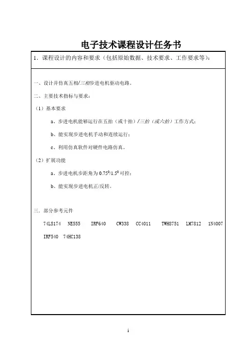
电子技术课程设计任务书1.课程设计的内容和要求(包括原始数据、技术要求、工作要求等) :一、设计并仿真五相/三相步进电机驱动电路。
二、主要技术指标与要求: (1)基本要求 a、步进电机能够运行在五拍(或十拍)/三拍(或六拍)工作方式; b、能实现步进电机手动和连续运行; c、利用仿真软件对硬件电路仿真。
(2)扩展功能 a、步进电机步距角为 0.750/1.50 可控; b、能实现步进电机正/反转。
三.部分参考元件 74LS174 IRF540 NE555 74HC138 IRF640 CW338 CC4011 TWH8751 LM7812 1N4007i电子技术课程设计任务书2.对课程设计成果的要求〔包括图表、实物等硬件要求〕 : 设计电路,安装调试或仿真,分析实验结果,并写出设计说明书。
要求图纸布局合理,符合工程要求,所有的器件的选择要有计算依据。
3.主要参考文献:[1] 彭介华. 电子技术课程设计指导[M]. 北京:高等教育出版社,1997 [2] 毕满清. 电子技术实验与课程设计[M]. 北京:机械工业出版社,1995 [3] 陈明义. 电工电子技术课程设计指导[M]. 长沙:中南大学出版社,2002 [4] 陈永甫. 新编 555 集成电路应用 800 例[M]. 北京:电子工业出版社 [5] . [6] 陈隆昌.控制电机[M]. 西安:西安电子科技大学出版社,2004 20004.课程设计工作进度计划: 序号1 2 3 4 5 6 7起 迄 日 期2010-1-10 2010-1-11 2010-1-12 2010-1-13 2010-1-14~2010-1-21 2010-1-22 2010-1-23 徐祖华工 作 内 容布置任务,教师讲解设计方法及要求 学生查找阅读资料,并确定方案 学生设计小组会议,讨论方案 设计及计算 仿真实验并写说明书,小组讨论 答辩 答辩 日期: 2010 年 1 月 6 日指导教师ii。
步进电机及其驱动电路原理图2012年05月21日14:20 来源:本站整理作者:秩名我要评论(6)步进电机是工业控制及仪表中最常用的控制元件之一,它有输入脉冲与电机轴转成比例的特征,在智能机器人、软盘驱动器、数据机床中广泛运用,微电脑控制步进电机最适宜系统中设计使用20BY-0型号步进电机,它实用+5V直流电源,步距角为18度,电机线圈由四相组成。
步进电机是工业控制及仪表中最常用的控制元件之一,它有输入脉冲与电机轴转成比例的特征,在智能机器人、软盘驱动器、数据机床中广泛运用,微电脑控制步进电机最适宜系统中设计使用20BY-0型号步进电机,它实用+5V直流电源,步距角为18度,电机线圈由四相组成。
如下图所示,即A、B、C、D四相。
驱动电路由脉冲信号控制,所以调节脉冲信号的频率便可以改变步进电机的转速。
途中BA、BB、BC、BD即为脉冲信号输入插孔,驱动器输出A、B、C、D接步进电机。
原理步进电机是将电脉冲信号转变为角位移或线位移的开环控制元件。
在非超载的情况下,电机的转速、停止的位置只取决于脉冲信号的频率和脉冲数,而不受负载变化的影响,即给电机加一个脉冲信号,电机则转过一个步距角。
这一线性关系的存在,加上步进电机只有周期性的误差而无累积误差等特点。
使得在速度、位置等控制领域用步进电机来控制变的非常的简单。
虽然步进电机已被广泛地应用,但步进电机并不能象普通的直流电机,交流电机在常规下使用。
它必须由双环形脉冲信号、功率驱动电路等组成控制系统方可使用。
因此用好步进电机却非易事,它涉及到机械、电机、电子及计算机等许多专业知识。
目前,生产步进电机的厂家的确不少,但具有专业技术人员,能够自行开发,研制的厂家却非常少,大部分的厂家只一、二十人,连最基本的设备都没有。
仅仅处于一种盲目的仿制阶段。
这就给户在产品选型、使用中造成许多麻烦。
鉴于上述情况,我们决定以广泛的感应子式步进电机为例。
叙述其基本工作原理。
望能对广大用户在选型、使用、及整机改进时有所帮助。
( Word to PDF - 未滨册 ) / Development of a Novel Drive Topology for a FivePhase Stepper MotorT.S. Weerakoon and L. SamaranayakeDept. of Electrical and Electronic Engineering, Faculty of Engineering, University of Peradeniya, Sri LankaAbstract-In this paper, a novel drive topology for a five phase stepper motor is described in detail. Commercially off the shelf, low cost, standard stepper motor drive ICs are used to derive a novel drive topology for five phase stepper motors which enables closed loop speed and position control powered by inner current control loop. It is proved that the derived topology can be generalized to any stepper motor with higher odd number of phases.The designed driver consists of full step, half step, clockwise and counter clockwise drive modes with the speed control and current control.I. INTRODUCTIONIn most of the robotics and automation engineering designs various types of stepper motors are used to obtain the required motion profiles. Stepper motors are preferred, as they do not require frequent maintenance and due to their ability to operate in many harsh environments. Selection of the motors and their drive circuits depend on the required performance characteristics of the applications. The two phase and four phase stepper motors are the most common types available in the market.However, for applications requiring high precision, low noise and lower vibration, Five Phase Stepper Motors are used. Due to smaller step angle, five phase stepper motors offer higher resolution, lower vibration and higher accelerations and decelerations. Therefore it is essential to make sure that these motor characteristics can be obtained from the designed drive topology.Because the five phase stepper motors are a rarely used type in the robotic applications and the construction is typically complicated, it is very difficult to find driver ICs, which are manufactured exclusive for them. As a result, the available Driver circuits for five phase stepper motors are very expensive.Using the available drive control ICs manufactured for common kinds of stepper motors such as 2 phased and 4 phased and using them in modeling new driver topology for other stepper motors would be a cost effective approach.The IC L297 integrates all the control circuitry required to control bipolar and unipolar stepper motors. The L298N dual H bridge drive forms a complete microprocessor to stepper motor interface. Here, novel drive topology is investigated and developed for five phase stepper motors by adding a microprocessor and logical control system with L297 and L298N. The complete topology is described in this paper. Section II explains the component characteristics. Section III is on the control logic circuit design phenomena. The interface design is given in Section IV with results in Section V. Finally the conclusions are presented in Section VI.II. CHARACTERISTIC ANALYSIS OF MAIN COMPONENTS The IC L297 can be used with an H bridge driver IC for motor drive applications as( Word to PDF - 未滨册 ) /shown in Fig.1. In this design H bridge function is achieved from the L298N or L293E. This may change depending on the power rating of the motor. The control signals to the L297 may be received from microcontroller or from external switches. A single IC can drive a 2 phase bipolar permanent magnet motor, a 4 phase unipolar permanent magnet motor or a 4 phase variable reluctance motor. Because very few electronic components are used, it has many advantages such as lower cost, higher reliability and the ability to house in a comparatively smaller space. The L297 generates three modes of phase sequences, namely half step mode, full step mode and wave mode depending on the input signals it receives.Fig. 1. Circuit diagram to drive a 2 phase bipolar or 4 phase unipolar stepper motor using L297 and L298N ICsA.CURRENT CONTROLSmall stepper motors generally need small DC supplies that control the winding currents and they are limited by the winding resistances. On the other hand, motors with the larger rated torque values have windings with smaller resistances. Therefore, they require a controlled current supply.The L297 provides load current control in the form of two Pulse Width Modulation (PWM) chopper circuits and each chopper circuit consists of a comparator, a flip-flop and an external sensing resistor.In this method, while the motor current is increasing, the control system applies the supply voltage to the motor. When the current is reached up to the threshold, the control system tries to maintain the current at the desired value by changing the duty ratio of the voltage supply as shown in Fig.2. For each chopper circuit, the duty ratio (D) of the voltage supply to the motor is defined as:D = T on / (T on + T off),where the T on and T off are switch on and off durations respectively of the H bridge. In the chopper circuit, the flip-flop is set by each pulse from the oscillator, enabling the output and allowing the load current to increase. As it increases the voltage across the sensing resistor increases and when this voltage reaches V ref the flip-flop is reset, disabling the output until the next oscillator pulse arrives. In this method V ref determines the peak load current.( Word to PDF - 未滨册 ) /Fig. 2. Circuit containing the flip-flop,the oscillator and the comparator used F ig.3. PWM operation of the voltage for current control for current controllingFig.3 shows how the current through the motor is controlled. When the motor current goes beyond the set point, the voltage applied to the motor terminal will be grounded. Therefore the current will decay and finally the motor current can be controlled.The L298N is a monolithic circuit contains two H bridges. In addition, the emitter connections of the lower transistors are brought out to external terminals allowing the connection of current sensing resisters.B. CURRENT CONTROL IN INHIBIT CHOPPER MODEInhibit chopper control mode and phase line chopper control mode are two of the most common types of current control techniques available. In the latter case when the voltage across the sensing resistor reaches to V ref, only the low side switch is made off. Hence this method is not suitable and inhibit chopper control mode has to be used. The required switching sequences for this can be taken directly from L297.Inhibit chopper mode can be selected by pulling down (grounded) the CONTROL input signal of L297. Then chopper acts on INH to control the current through the motor coils. Therefore the contribution of INH signal generated from L297 is very important to create ENABLE signal for L298N. In the case when the voltage across the sensing resister reaches to V ref, the chopper flip-flop is reset and INH is activated and is brought to low. Then it turns off all four switches of the bridge. The chopping frequency is determined by the internal oscillator of the L297. After switching off all transistors, the diodes provide a path to divert the winding current. The switches of the H bridge are made on in the next oscillator cycle.Fig.4 explains current control phenomena at an instant when phase signal A is high and B is low. These A and B signals are fed to two AND gates connected to low and high side switches in the L298N to generate excitation signal with the same INH1 signal in order to control the load current. The AND gate output will become high only if and only if the INH1 is high.( Word to PDF - 未滨册 ) /Fig. 4. Inhibit chopper waveform when CONTROL is LOWIII. LOGIC CIRCUIT DESIGNINGIn any mode of operations, wave patterns of A, B, C and D phases of the L297 repeat after four clock cycles as shown in Fig.5. Translation of the repetition of the phase waveform after the ten clock cycles is essential to derive the drive topology for the five phase stepper motor.Fig. 5. In the normal operation, L297 two phases of a 4 phase stepper motor or two ends of a 2 phase stepper motor winding are made ON at a time and the sequence repeats after every 4 clock cycles( Word to PDF - 未滨册 ) /Fig. 6. Five phase excitation sequenceBy analyzing the three modes of operations of the L297, it is clear that in the normaldrive mode, which is usually called as two-phase-on drive mode, should be selected to achieve the required excitation sequence for a 5 phase stepper motor as shown in the Fig.6.By studying the required excitation sequence for 5 phase stepper motor and A, B, C, Dphase sequences of the L297, the required logic circuit was designed. The procedure mentioned below was followed.(i) Separation of High and Low side transistor excitation pattern for each phasefrom five phase excitation sequences as shown in Fig.6.(ii) Selection of suitable phases from A, B, C and D of L297 to generate the highside excitation sequences.(iii) Generating input signals to the L298N using A, B, C, D output signals of themicrocontroller and the relevant AND gates.(iv) Create ENA (enable A) and ENB (enable B) signals for L298NBy dividing ten (10) steps of required phase pattern in to twenty (20) steps can be equated to the four clock cycles of output wave pattern generated by the L297. The Fig.7 explains the clock cycle selection for required high and low side excitation sequence.High side transistor excitation sequence can be generated from L297 by selectingsuitable output phases of the L297. The selected order, which is the two-phase-on mode of L297 is shown in the Fig.8. The microcontroller signals are used to generate the required high side pulse patterns. The DM74LS08 Quad 2-Input AND Gates are used to AND microcontroller signals and signals received from L297.As shown in Fig.9, the input signals and Enable signals determine the high side and low side transistor switching patterns. Therefore ENABLED (EN) signals are fed from the microcontroller. But to achieve current control of the motor INH signal must engaged with the Enabled signal to the L298N as explained under current control section. The Fig.10 explains how the EN signal to L298N is generated using the required Enable( Word to PDF - 未滨册 ) /signal created by the microcontroller and Inhibit (INH) signal from L297. An AND operation of these two signals generates the relevant EN signal for L298N.Fig. 7. Required High and Low side transistor excitation sequencesFig. 8. Generation of Input signals to the L298NThe L298N consists with H-bridges and one output of a bridge was used for a phase. Two inputs of one H bridge is dependent each other. Therefore both outputs of a single bridge cannot be used. To generate five phases, it is required to have three numbers of L298N dual full bridge driver ICs. The selection of inputs and outputs of L298N are( Word to PDF - 未滨册 ) /shown in Fig.13 of Section IV.Fig. 9. Pull up and Pull down operation of L298NFig.10. Generation of ENABLED signalIV. INTERFACE DESIGNINGThe logic circuitry used to generate required input signals for L298N and microcontroller control signals play a major role in the driver circuit. The Fig.11 shows interface of L297, DM74LS08 Quad 2-Input AND Gates ICs and L298N with the microcontroller PIC16F877A.The circuit configuration for L297 is shown in Fig.12. The control signal has to be grounded to obtain the inhibit control mode in order to limit the current through the( Word to PDF - 未滨册 ) /motor windings. The CLOCK signal is supplied by the microcontroller and HALF/FULL pin should always to be low for full mode (two-phase-on) of operation. The ENABLED signal is used to control the motion of the motor. When it is low, all INH1, INH2, A, B, C, D pins are brought to low. The V ref value sets the current flowing through the motor. There are two L297 ICs used and it is necessary to synchronize them. It can be done easily by using the SYNC pin of L297.Fig. 11. Block diagram of the systemThe Fig.13 shows how the input and output terminals are used in L298N. Usually 100nF non-inductive capacitors are used between both V s and V c with the ground. The value of the current sensing resistor has to be as small as 0.5Ω in order to avoid large voltage drops at large currents.External diode bridges provide current circulating paths when the inputs of the IC are chopped. Usually Schottky diodes are used here because they are faster in recovery.V. RESULTSThe theoretical and logical analysis of the stepper drive circuit design approach shows that it is a simple construction having several modes of operation and control.( Word to PDF - 未滨册 ) /Fig. 12. Configuration of L297 Fig.13. Configuration of L298NThe performance of the stepper drive circuit shown in the Fig.14 was tested for the following capabilities:1. Speed control capability2. Current control capabilityThe Fig.15 (a) and (b) show the excitation wave forms at each phase terminal. The excitation sequences for all five phases reveal that they are working according to the requirement. Fig.15 (b) shows additional orange and green phase excitation sequences to compare the black phase excitation with the others. Due to the charging and the discharging of the capacitors by the current flowing through the windings of the motor, there are some transients at each excitation points.The speed control of the motor has been achieved by varying the frequency of the excitation sequence of the five terminals. It is clearly shown that the pulse width of the voltage sequences of Fig.15 (a), (b) gets doubled in the Fig.16 (a), (b) in same time scale of 5ms/div. It is observed that the rotating speed (speed 1) of the motor relevant to the excitation sequence shown in Fig.15 is half that of the speed (speed 2) of the excitation sequence shown in Fig.16. Hence by varying the pulse frequency of the excitation sequence generated by the PIC microcontroller, the speed of the motor can be varied.( Word to PDF - 未滨册 ) /Fig. 14. Drive circuit with microcontroller( Word to PDF - 未滨册 ) /Fig. 15(a). Voltages of the Blue, Red, Orange and Green phases at speed 1( Word to PDF - 未滨册 ) / Fig. 15(b). Voltages of the Orange, Green and Black phases at speed 1Fig. 16 (a). Voltages of Blue, Red, Orange and Green phases at speed 2( Word to PDF - 未滨册 ) /Fig. 16 (b). Voltages of the Red, Orange, Green and Black phases at speed 2The current controlling capability of the motor drive circuit has been demonstrated in the Fig.17(a), (b), (c). For the sake of demonstration, only the RED phase has been considered and Fig.17(a) shows the current wave at higher V ref(=600mV) which is greater than the V sense. Then the INH signal does not pull down to limit the current absorb by the motor. Each phase has positive and negative current components, because the phase voltage varies from +V s, +V s/2 to 0V and current to the phase varies from positive, zero to negative respectively, corresponding to the latter voltage variation. By chopping the inhibit (INH) signal to the L298N, the voltage at the motor terminals is limited to control the current through each winding.( Word to PDF - 未滨册 ) /Fig. 17(a). Phase Current and INH signal variation at V ref= 120 mVFig. 17 (b) and (c) show the current controlling capability at two different V ref values of 200mV and 120 mV.Fig. 17(b). Phase Current and INH signal variation at V ref = 200 mV( Word to PDF - 未滨册 ) /Fig. 17(c). Phase Current and INH signal variation at V ref= 120 mVVI. CONCLUSIONSThe proposed novel drive for 5 phase stepper motor is a cost effective motor drivercompared to the available stepper motor drive circuits in the market. Since the driver has necessary controlling, it can be used for five phase stepper motors for generalapplications.The simple construction and compacted design of the driver provides another advantagethat the driver can be used for robotics applications because it requires small space. Finally the designed driver can be considered as a prototype of a low cost five phase stepper motor drive circuit having additional many functions such as current control, speed control etc. It can be introduced to the local market as a low cost compact drive circuit.REFERENCES[1] N.Sedaghati Mokhtari, “Micro-step Driving for Stepper Motor: A Case Study”, Available:http://ece.ut.ac.ir/silab/publications/pdf/sedaghati_iscee06.pdf[2] Data sheet of the L297 IC, Available:/datasheets_pdf/L/2/9/7/L297.shtml[3] Data sheet of the L298N IC, Avilable:/datasheets_pdf/L/2/9/8/L298N.shtml[4] Thomas L. Hopkins ‘Stepper motor driver considerations common problems and solutions”, Available:/InfoWeb/design_center/Appnotes_Archive/1675. pdf[5] H.Sax, “Stepper motor driving applications note”, Available:( Word to PDF - 未滨册 ) / /myfiles/data/1679.pdf。
毕业设计(论文)学院专业姓名XX大学毕业设计(论文)任务书站名姓名专业年级设计(或论文)题目:五相步进电动机控制完成日期:年月日具体要求:1、要求对五相步进电动机五个绕组依次自动实现如下方式的循环通电控制:第一步:A—B—C—D—E第二步:A—AB—BC—CD-DE-EA第三步:AB—ABC-BC-BCD-CD—CDE—DE-DEA第四步:EA-ABC—BCD-CDE—DEA五相步进电动机的模拟控制的实验面板图:图所示前言随着现代工业自动化的日益发展,电动机作为重要的电器元件,被广泛的应用在各种自动化控制系统中.步进电动机由于其具有易于电脑操作、步数误差小、精度高、使用系统时间长和成本低等优点,被广泛应用于工业控制中。
其中五相混合式步进电机总体性能优于其它种类的步进电动机,是工业上应用最为广泛的步进电动机品种,被广泛的应用在各个领域中。
所以对五相步进电动机实现自动化是工业自动化的必然趋势。
打印机作为计算机的输出设备之一,运用步进电动机作为打印机的字车动力源和走纸机构,通过牵引机构将步进电动机的转动转变为走纸移动,可以实现打印纸的纵向移动,因其要求精度比较高,所以,打印机的走纸结构能够使用五相步进电动机来控制。
对五相步进电动机的使用,工业中应用比较广泛,但大都应用于高精度的机床控制系统中,整个系统比较庞大,所以,本文以步进电动机在的打印机中的精密控制为背景介绍使用PLC控制五相步进电动机按照给定频率自动运行和自由调速的模拟控制方法.摘要主要阐述了以五相步进电动机在针式打印机走纸结构中的应用为背景,介绍了一种用三菱FX—2N系列PLC实现对规格型号90BYG550A-0301的五相步进电动机控制的方法,利用PLC产生脉冲信号对五相步进电动机进行模拟控制,实现对五相步进电动机五个绕组的通电状态,达到五相步进电动机按照固定速度的循环自动运行的目的,并实现步进电动机正反转和调速控制.用PLC控制五相步进电动机驱动针式打印机的走纸结构控制纸张的进退,实现打印机的打印工作。
-13-!应用与设计五相步进电机控制系统研究长沙电力学院曾吉吉昭湖南教育学院张小兵Study of a Control System on the 5-Phase Step -MotorZeng ZhezhaoZhang Xiaobing摘要:CIPH9803A 是一种可编程五相步进电机控制芯片,它具有步数、递转启动、停止、暂停、高速、快速等多种设置功能。
文中介绍了CIPH9803A 的引脚功能和工作原理,并给出了其在五相步进电机控制系统中的应用电路。
关键词:CIPH9803A;五相步进电机;控制系统分类号:TM383.6文献标识码:B文章编号:1006-6977(2002)02-0013-01五相步进电机控制系统研究图1CIPH9803A 的引脚排列1引言CIPH9803A 是一种可编程五相步进电机控制芯片。
该芯片具有步数设置(最大步数高达100万步)、可逆运转、启动、停车、暂停、工速、快速等多种设置功能,它具有一个传感信号输入端口,可控制步进电机的定位停车。
实际应用表明,以CIPH9803A 专用芯片为核心的五相步进电机控制电路具有成本低、可靠性高等优点,特别适合机床设备的技术改造。
2引脚功能和技术参数2.1引脚功能CIPH9803A 芯片的引脚排列如图1所示。
各引脚功能如下:RST:复位引脚,高电平有效,正常工作时,该引脚应为低电平;OUT1~OUT5:分别为五相步进电机的A ~E 相的激励输出,均为负脉冲有效,负载电流小于25mA ;XTAL1、XTAL2:晶体振荡电路接入端;STOP:步进电机停车输入端,负脉冲有效。
当步进电机运行到指定位置时,可将光电传感器产生的负脉冲输入到该端,以自动停止步进电机的运行;LED :按键指示输出端,低电平有效。
在键盘的任一键按下时,该端输出低电平;GND:电源地;VDD:电源正端(+2.7~+6.5V );C1~C4:分别用于连接行列式键盘的第1~4列;R1~R4:分别用于连接行列式键盘的第1~4行。
一种新的五相步进电机驱动电路开发 T.S. 维拉孔和 T. 萨马拉纳亚克斯里兰卡,佩勒代尼耶大学工程学院,电子与电气工程学院付自刚译摘要本文详细地介绍了一种新的五相步进电机驱动电路。
这种新的驱动电路是由商业上现成的,廉价的,标准的步进电机驱动 IC 搭建,它能实现由内部电流回路驱动的闭环速度和位置控制。
经证明, 这种驱动电路能推广到任何更多相数的奇数相的步进电机。
这种驱动电路具有速度控制和方向控制,包括全步、半步、顺时针、逆时针控制模式。
一、概述在大多数机器人和自动化工程设计中, 各种各样步进电机都被广泛应用来得到需要的运动姿态。
步进电机倍受人们青睐是因为它不需要频繁的维护并能在苛刻的环境中运行。
步进电机及其驱动器的选择要根据具体应用中需要的效果来决定。
市场上最常见的是两相和四相步进电机。
可是,实际应用中要求高精度,低噪声和低震动,因此五相步进电机得以应用。
因为步距角较小, 五相步进电机有较高的分辨率, 较低的震动和良好的加速与减速特性。
因此, 确保设计的驱动电路能使步进电机充分发挥这些优点非常重要。
因为在机器人应用中是很少见得类型,而且结构很复杂,很难找到它们的驱动IC ,只能专门定做。
结果导致五相步进电机的驱动电路产品异常昂贵。
用普通步进电机如二相与四相步进电机的驱动控制 IC 来制作其它步进电机的驱动电路是一种经济有效的方法。
L297继承了控制单极性和双极性步进电机所需要的所有控制电路系统。
L298N 双 H 桥驱动器形成了一个完善的步进电机微处理器接口。
在这里,我们通过给 L297和 L298N 加上微处理器和逻辑控制系统研究开发出了一种新的五相步进电机驱动电路。
第二部分解释了元器件特性。
第三部分介绍了控制逻辑电路设计。
第四部分是接口设计,结果在第五部分。
最后,第六部分加以总结。
二、主要元器件特性分析如图一所示,集成块 L297可以与 H 桥集成电路一起使用作为步进电机驱动器。
在该设计中, H 桥的功能用 L298N 或者 L293E 实现。
这要根据步进电机的额定功率而定。
输入 L297的控制信号可能来自为控制器或者外部开关。
一个 IC 能驱动一个两相双极性永磁式步进电机, 一个四相单极性永磁式步进电机或者一个四相变磁阻式步进电机。
因为用到的电子元器件非常少, 该设计好处颇多, 比如,花费少,可靠性高,占用的空间相对较小。
按照接收到的输入信号的不同,L297产生三种不同模式的相位序列,即半步模式,全步模式和波形模式。
图一用 L297和 L298N 构成的驱动一个两相单极性步进电机或一个四相单极性步进电机的电路图A. 电流控制小型步进电机一般小型直流电源来控制绕组电流,它们的绕组电阻也是有限制的。
在另一方面, 拥有较大额定扭矩值的步进电机具有较小的绕组电阻。
因此, 它们需要对电流进行控制。
L297以两个脉冲宽度调制(PWM 斩波电路的形式提供负载电流控制,每个斩波电路由一个比较器,一个触发器和一个外部感应电阻组成。
在该理论中,当电机电流增加时,控制系统将电源电压施加到电机。
如图二所示, 当电流值达到阈值时, 控制系统将通过改变电源电压的占空比来维持电流的期望值。
对于每一个斩波电路来说, 步进电机电源电压的占空比 (D 定义为: D = Ton / (Ton + Toff ,其中 T on 和 T off 分别是 H 桥的导通和断开时间。
在斩波电路中,触发器由来自振荡器的各个脉冲置位,从而允许输出和允许负载电流增长。
感应电阻两端的电压随着负载电流的增长而增长, 当电压增长到 V ref 时, 触发器被重置,输出中断直到下次振荡器脉冲到来。
在该方法中, V ref 决定了负载电流的峰值。
图二包含触发器、振荡器和电压比较器的电流控制电路图三用于电流控制的 PWM 操作的电压图三展示了穿过电机的电流是如何被控制的。
当电机的电流超过设定值时, 施加于电机端得电压将降为零。
因此,电流将会衰减,最终电机电流被控制住。
L298N 是一块包含着两个 H 桥的单片集成电路。
此外, 低位晶体管的发射极被引出来作为扩展端子以允许电流敏感电阻的连接。
B .抑制斩波模式下的电流控制抑制斩波控制模式和相位线斩波控制模式是当今两种最常见的电流控制技术。
在后一种方式中, 当敏感电阻的电压达到 V ref 时 , 只有低端的开关断开。
因此这种方法并不适用,我们选用抑制斩波模式。
需要的开关序列可以直接来自L297N 。
抑制斩波模式可以通过将 L297N 的 CONTROL 端接地实现。
然后斩波作用于INH 端来控制通过电机线圈的电流。
因此, L297输出的 INH 信号对创造 L298N 的使能信号起着非常重要的作用。
在敏感电阻的电压达到 V ref 的情况下, 斩波触发器被重置, INH 端子被激活并处于低电平状态。
然后,所有四个桥电路截止。
斩波频率由 L2907内部的振荡器决定。
在所有的晶体管截止之后,二极管为绕组电流提供转移通路。
在下一个振荡周期里, H 桥导通。
图四说明了当相信号 A 处于高电平而相信号 B 处于低电平的时刻的电流控制情况。
为了产生和 INH1信号相同的激发信号来控制负载电流,这些 A 和 B 信号被输入到与 L298N 中高、低电平开关相连的两个与门。
当且仅当 INH1为高电平时,与门的输出为高电平。
图四当 CONTROL 为低电平时的抑制斩波波形三、逻辑电路设计如图五所示,在任何运行模式下, L297的 A,B,C,D 相的波形每隔四个时钟周期重复一次。
为构建五相步进电机驱动电路, 在十个时钟周期之后对相波形进行转换十分重要。
图五在一般工作模式下, L297四相步进电机的两相或者两相步进电机绕组被导通, 每四个时钟周期后序列重复图六五相激励序列通过分析 L297的 3种工作模式,很明显应该选择一般工作模式,也通常被称作两相导通模式,来产生如图六所示的激励五相步进电机的序列。
通过研究五相步进电机所需要的激励序列和 L297的 A,B,C,D 相序列来设计出需要的逻辑电路。
按照下列步骤进行。
1、如图六所示,从五相的激励序列中分离出每一相的高低侧晶体管激励模式。
2、从 L297的 A,B,C,D 选出合适的相位来产生高侧激励序列。
3、利用微控制器的 A,B,C,D 输出信号和相关的与门产生 L298N 的输入信号。
4、产生 L298N 的 ENA (A 使能和 ENB (B 使能信号。
将 10步的相型分为 20步等同于 L297输出的四个时钟周期的相型。
图七解释了高、低侧激励序列的时钟周期选择。
通过选择 L297的合适的输出相位,可以产生高侧晶体管的激励序列。
已经选择的顺序,即 L297的两相导通模式如图八所示。
微控制器信号用以产生所需的高侧脉冲模型。
有四个输入端的 DM74LS08含有两个门, 用来将接收到的 L297信号和微控制器信号相与。
如图九所示,输入信号和使能信号共同决定了高低侧晶体管的开关模式。
因此,微控制器提供了使能(EN 信号。
但是为了达控制电机电流的目的, INH 信号必须与L298N 的使能信号衔接,这在下面的电流控制部分会有解释。
图十解释了怎样利用由微控制器产生的所需的使能信号和来自 L297的抑制(INH 信号来产生 L298N 的EN 信号。
这两种信号的与操作产生了 L298N 相关的 EN 信号。
图七需要的高低侧晶体管的激励序列图八 L298N 输入信号的产生L298N包含两个H桥,其中一个H桥的输出端被用作一相。
H桥的两个输入端彼此独立。
因此,单独一个H桥的两个输出端都无法使用。
为了产生五个相数(的信号,需要使用3个L298N双H桥驱动IC。
L298N的输入端与输出端选择将在第四部分的图十三中加以说明。
图九L298N的拉高与接低操作图十使能信号的产生四、接口设计用以产生L298N需要的输入信号的逻辑电路和微控制器控制信号在驱动电路中扮演着主要角色。
图十一展示了L297的接口,DM74LS08双与门IC和与微控制器PIC16F877A相连的L298N。
图十二说明了电路的配置。
为了限制通过电机绕组的电流,控制信号必须接地以进入抑制控制模式。
微控制器提供了CLOCK信号,HALF/FULL引脚必须接地来进入全步模式(两相导通模式。
ENABLED是用来控制电机运转的。
当它处于低电平状态时,INH1, INH2, A, B, C, D都被置于低电平状态。
V ref的取值设定了通过电机的电流。
这里用到了两个L297,必须使它们同步。
这可以通过使用L297的SYNC引脚轻易做到。
图十一系统框图图十三说明了L298N的输入与输出端的使用方法。
通常会在V s和V c与地之间使用100nF的无感电容。
为了避免大电流时的大幅度电压降落,电流敏感电阻器的阻值必须小到0.5Ω。
当IC的输入被截断时,外部桥式二极管提供电流通路。
这里通常使用肖特基二极管,因为肖特基二极管容易恢复。
五、结论对步进电机驱动电路的设计方式的理论分析和逻辑分析显示了驱动电路是一种具有几种操作模式和控制模式的简单结构。
图十二L297的配置图十三L298N的配置如图十四所示的步进电机驱动电路实物通过了下列性能测试:1.速度控制性能2.电流控制性能图十五(a和(b展示了在每一相线端得激励信号波形。
步进电机五相的激励序列说明它们是按要求工作的。
图15(b显示了橙色的和绿色的激励序列来使黑色的激励序列与其他激励序列相比较。
因为流过电机绕组的电流会使电容器充放电,在每一个激励点都会发生突变。
通过变换电机五相的激励序列的频率,可以达到控制电机速度的目的。
可以明显地看到,在相同的时间分辨率5ms/div 下,在图十六(a,(b 中的电压序列的脉冲宽度是图十五(a,(b中的两倍。
可以看出,与图十五所示的激励序列相关的步进电机的转动速度(速度1是与图十六所示激励序列相关的步进电机转动速度的一半。
因此,通过改变由PIC微控制器产生的激励序列的脉冲频率,步进电机的速度也随之改变。
图十四带微控制器的驱动电路图十五(a在速度1下的蓝、红、橙、绿相电压图15(b在速度1下的橙,绿、黑相电压图16(a在速度2下的蓝、红、橙绿相电压图16(b在速度2下的红、橙、绿、黑相电压图17(a、(b、(c证明了该步进电机驱动电路的电流控制能力。
为了达到证明效果,这里只考虑了红色相电压,图17给出了在更高的V ref (=600mV下的电流波形,该电压高于V sense。
此时,INH信号并未接地来限制通过步进电机的电流。
每一相都有正负电流部分,因为相电压从+V s, +V s/2变化到0V,相电流也分别从正、零变为负,相当于后者的电压变化。
通过截断L298N的抑制信号(INH 信号,电机端子上的电压被限制以控制通过电机绕组的电流。