MMBD7000HS-7-F
- 格式:pdf
- 大小:78.85 KB
- 文档页数:4

M-7000Introduction:Congratulations on your purchase of an M-7000 powered loudspeaker, engineered and manufactured by Britelite Enterprises. The M-7000 includes a high-output compression driver, and 15” woofer to produce an even, smooth studio quality sound in a sound reinforcement speaker. Our design goal was to build a speaker with accurate playback, smooth dispersion of mid and high frequencies and an ergonomic design for easy transport and setup. The result is a sound reinforcement system dynamic enough to use at home, in the studio, parties or in home theater.Features:2-way amplified Active Speaker2X15” Long-throw woofer with high-temperature voice coilUltra-wide, smooth dispersion of high and mid frequenciesMic/Line input and pass-thru connectorUSB & SD Card input supports .wav & MP3Bluetooth Compatible with TWSLED lightingCautions:1. All Operating Instructions should be read before using this equipment.2. To reduce the risk of electrical shock, do not open this unit. There are NO REPLACEABLE PARTS INSIDE. Please refer servicing to a qualified service technician.3. Do not expose this unit to direct sunlight or to a heat source such as a radiator or stove.4. This unit should only be cleaned with a damp cloth. Avoid solvents or other cleaning detergents.5. When moving this equipment, it should be placed in its original carton and packaging. This will reduce the risk of damage during transit.6. DO NOT EXPOSE THIS UNIT TO RAIN OR MOISTURE.7. DO NOT US ANY SPRAY CLEANER OR LUBRICANT ON ANY CONTROLS OR SWITCHES8. Make sure All of your equipment is completely OFF and lower ALL VOLUME, LEVEL & GAIN controls before connecting a sound source.9. Only LINE LEVEL SIGNALS SHOULD BE SENT TO YOUR SPEAKER.Disregarding any of the above will void your warrantyFunctions1. MP3 module:2. Treble volume : Control the Volume of treble3. Bass volume : Control the Volume of bass4. Master volume : Control the Volume of speaker .5. Line input volume: Control the Volume of line input6. Microphone volume: Control the Volume of microphone input7. Mircophone input: XLR microphone input8. RCA line input& output9. Mircophone input: 6.35 jack microphone input10. Line input: XLR11. Line output: XLR12.Power on/off13. Power Cord Connector - Connect here an IEC main power cable in order to supplythe unit.14.LED lighting on/off15.115-230 voltage switchPlacement Tips-Avoid placing loudspeakers in the corners of a room. This increases thelow-frequency output and can cause the sound to be muddy and indistinct.-Avoid placing loudspeakers against a wall. This, too, increases the low frequency output, though not as much as corner placement. However, if you do need to reinforce the low frequencies, this is a good way to do it.-Avoid placing the active speakers directly on a hollow stage floor. A hollow stage can resonate at certain frequencies, causing peaks and dips in the frequency response of the room. It’s better to place the speakers on a sturdy table or tripod stands.-Position the speakers so the high-frequency drivers are two to four feet above ear level to the audience to maintain high frequency quality.TroubleshootingNo Power-First check to make sure the speaker is plugged in to a live AC outlet.Make sure the POWER switch is on.No Sound-Make sure input LEVEL control turned up.-Make sure signal source is working and the connecting cables are in good shape and securely connected at both ends. Make sure the output volume control on the mixing console is turned up.-Make sure the preamp or mixer does not have a Mute button engaged.Bad Sound – Noise - HummingIf the sound is loud and distorted, verify that the levels are set properly on the speaker and mixing console.Make sure all connectors are secure and they are plugged in to the proper connector (i.e., Mic cable plugged in to MIC input, Line level source plugged in to Line Level Input. It is a good idea to periodically clean all electrical connections with anon-lubricating electrical contact cleaner.Make sure none of the signal cables are routed near AC cables, power transformers or other electrical power cords.If humming occurs, turn the LEVEL control of the speaker all the way down. If the noise disappears, it’s coming from the signal source. If not, try disconnecting the cable connected to the INPUT jack. If the noise disappears, it could be a “ground loop,” Try the following ideas:o Use balanced connections throughout your system for best noise rejection. (XLROPERATIONS MANUAL FOR EDISON PROFESSIONALcables, balanced ¼” jacks; RCA cables are not balanced)o Whenever possible, plug all the audio equipment’s power cords into the same outlet. o The hum may appear when using an unbalanced source (CD player, iPod, etc.). Use can use an RCA to XLR adapter to turn an unbalanced cable to a balanced cable. o If the hum persists, try removing components one at a time from the back of the mixer and check each for hum. Reducing the Bass or Treble levels (10 and 11) may reduce humming.Care and MaintenanceYour active speakers will provide many years of reliable service if you follow these guidelines:Avoid exposing the loudspeaker to moisture. If they are set up outdoors, be sure they are under cover if you expect rainAvoid exposure to extreme cold. If you must operate loudspeakers in a cold environment, warm up the voice coils slowly by sending a low-level signal through them for about 15 minutes prior to high-power operation.Use a dry cloth to clean the cabinets. Only do this when the power is turned off. Avoid getting moisture into any of the openings of the cabinet, particularly where the drivers are located.Limited WarrantyThis Limited Product Warranty is provided by Britelite Enterprises. Britelite warrants to Customer that the product is free from defects in materials and workmanship under normal use during the Warranty Period of 90 days for parts and 1-year labor. If the product fails to conform to the warranty then Britelite or its authorized service will either repair or replace any nonconforming product, provided that Customer gives notice of noncompliance within the Warranty Period to Britelite by emailing******************************************(Mexicocustomerscancall01554624 0251). Please retain the original dated receipt as evidence of proof of purchase.FCC Radiation Exposure Statement:This equipment complies with FCC radiation exposure limits set forth for an uncontrolled environment. This equipment should be installed and operated with minimum distance 20cm between the radiator & your body.FCC WarningThis device complies with Part 15 of the FCC Rules. Operation is subject to the following two conditions:(1) This device may not cause harmful interference, and (2) This device must accept any interference received, including interference that may cause undesired operation.NOTE 1: This equipment has been tested and found to comply with the limits for a Class B digital device, pursuant to part 15 of the FCC Rules. These limits are designed to provide reasonable protection against harmful interference in a residential installation. This equipment generates, uses and can radiate radio frequency energy and, if not installed and used in accordance with the instructions, may cause harmful interference to radio communications. However, there is no guarantee that interference will not occur in a particular installation. If this equipment does cause harmful interference to radio or television reception, which can be determined by turning the equipment off and on, the user is encouraged to try to correct the interference by one or more of the following measures:- Reorient or relocate the receiving antenna.- Increase the separation between the equipment and receiver.- Connect the equipment into an outlet on a circuit different from that to which the receiver is connected.- Consult the dealer or an experienced radio/TV technician for help.NOTE 2: Any changes or modifications to this unit not expressly approved by the party responsible for compliance could void the user's authority to operate the equipment.Please do not return the product to the dealer or place of purchase. Contact Britelite directly for warranty support.。


2订单号__________________________________________试验倾斜角度____________________________________最终倾斜角度____________________________________转速____________________________________________额定马力________________________________________ 风扇组件52102 钢毂板 110 工具包 - 叶片螺栓 111 叶片螺栓 120 工具包 - 中心钢毂盘五金件 121 帽螺栓 5/8 英寸 122 平面垫圈 5/8 英寸 123 卸扣 1/2 英寸 130 工具包 - 叶片螺栓五金件 131 机制螺栓 3/4 英寸 132 平面垫圈 3/4 英寸 133 六角自锁螺母 3/4 英寸或 六角螺母 3/4 英寸和自锁垫圈 3/4 英寸 134 螺纹脂 140 工具包 - 钢毂盘盖五金件 141 机制螺栓 3/8 英寸 142 平面垫圈 3/8 英寸 143 自锁垫圈 3/8 英寸 144 六角螺母 3/8 英寸 145 六角自锁螺母 3/8 英寸 146 垫片 150 工具包 - 平衡五金件 160 手册 170 工具包 - 钢毂盘支架 1930 毫米钢毂盘装配的必需配置 171 钢毂盘支架 172 机制螺栓 1/2 英寸 173 平面垫圈 1/2 英寸 174 六角自锁螺母 1/2 英寸200 叶片300 钢毂盘盖 图 1 - 典型风扇装配实际组件外观可能有所不同3➠注风扇钢毂盘安装以下指示信息详细说明在 Marl ey Geareducer ® 上安装 Marl ey HP7000 风扇的过程,该风扇配有使用带螺栓的风扇钢毂盘固定板的锥形风扇(输出)轴承或使用锥形分离轴衬的直叶式风扇轴承。
其他减速设备的安装可能有所不同。

Bondstrand ® Series 2000M-FP and 7000M-FP Fire-Resistant Fiberglass Pipe and FittingsBondstrand Series 2000M-FP is a fiberglass-reinforced epoxy resin piping system intended primarily for wet and dry deluge systems where excellent corrosion resistance as well as fire resistance are necessary and low weight is desired. Series 2000M-FP features a thick intumescent coating applied at the factory to the exterior of Series 2000M pipe and fittings. When exposed to fire, the coating expands to form an incombustible foam char that protects and insulates the piping. The intumescent coating is available in 5 mm and 8 mm thicknesses.Series 7000M-FP pipe and fittings are electrically conductive.• Offshore fire protection systems (wet and dry)• Onshore above ground fire protection piping• American Bureau of Shipping (U.S.) • Det Norske Veritas • Germanischer Lloyd• Lloyd’s Register of Shipping (U.K.)• National Sanitation Foundation (U.S.) • United Kingdom Offshore Operators Association• United States Coast GuardDescriptionUses and ApplicationsListings and Approvals forBondstrand Series 2000M-FP and 7000M-FPPiping SystemsBondstrand Series 2000M-FP and 7000M-FP have been demonstrated to be capable of maintaining service pressure following exposure to a hydrocarbon fire (temp ~ 2000°F) no less than 5 minutes duration in the dry condition, and 25 minutes in the full-flow condition with expectation that service life would exceed 6 hours.Pipe system design for pressure ratings up to: 17.2 bar (250 psi) for 1 - 16 inch and 16.0 bar (232 psi) for 18 - 40 inch, depending type of fittings. Refer to NOV Fiber Glass Systems.Individual system components may not have the same ratings as the pipe. Refer to the detailed product information for the specific components to determine the pressure rating for the system as a whole.PerformanceBondstrand products are manufactured to meet the highest standard of quality in accordance with ISO 9001. The products are designed to meet ANSI and ASTM standards. Bondstrand 2000M-FP and 7000M-FP piping meet all applicable requirements of ASTM F 1173 for fiberglass-reinforced resin pipe and fittings.Bondstrand 2000M-FP and 7000M-FP products have been tested by Southwest Research Institute (SwRI) for performance in jet fire conditions in accordance with UKOOA guidelines. The 2000M-FP and 7000M-FP system meets the requirements for fire endurance in a hydrocarbon jet fire, certified by SwRI.Testing and Standards•***************Pipe — Filament-wound fiberglass-reinforced epoxy pipe with nominal 0.020-inch (0.5 mm) integral resin-rich reinforced liner (2000M-FP) or with no liner, with comingled carbon fibers (7000M-FP) and 5 mm or 8 mm external intumescent coating. For typical physical and mechanical properties, refer to Bondstrand Product Data, Bondstrand Series 2000M and 7000M Fiberglass Pipe and Fittings for Shipboard and Offshore Platform Service.Fittings — Wide range of lined filament-wound fiberglass-reinforced epoxy fittings.Flanges — One-piece filament-wound fiberglass-reinforced epoxy resin flanges in heavy-duty hub-less configuration. Flange covers made with intumescent material is used to protect flanges. Joining systems — Quick-Lock straight/taper adhesive-bonded joint featuring integral pipe stop in bell for predictable, precise laying lengths. Taper/taper bonded joints supplied in larger sizes.Thermosetting adhesive for bonded joints – This includes both the Quick Lock and Taper/Taper joitns - PSX™•34 or PSX™•60 two-part epoxy adhesive.PSX•60 adhesive is conductive and is to be used on all installations of Bondstrand 7000M pipe.Typical joint lengths— All diameters are supplied in nominal 20 ft. (6.1m) lengths.Fittings — See Bondstrand Product Data, Series 2000M-FP and 7000M-FP Fittings, for dimen-sions, shipping weights and pressure ratings.90° and 45° elbows Deluge couplings sized to accept standard spray nozzles Tees and reducing tees Reducing saddles furnished with**Couplings * Quick-Lock® socket outlet Nipples * Flanged outlet ReducersFlanges — Series 2000M-FP and 7000M-FP flanges are offered in one configuration:• One-piece hubless (heavy duty)Bondstrand marine flanges are produced with the following drillings for easy connection to piping systems currently in common use; other drillings, as well as undrilled flanges, are available:• ANSI B16.5 Cl 150 & Cl 300 • JIS B2211 5 kg/cm 2• API 605 Cl 150 & Cl 300 • JIS B2212 10 kg/cm 2• ISO 2084 NP-10 & NP-16 • JIS B2213 16 kg/cm 2See Bondstrand Product Data,Series 2000M-FP and 7000M-FP Flanges for dimensions and weights for the drillings given above. Flange covers made of the intumescent material used on the exterior of the pipe are available and required for complete system performance in a fire situation.CharacteristicsFittings and FlangesInstallation2The installation procedures for Bondstrand Series 2000M-FP and 7000M-FP are described in Bond-strand Installation Guide. Standard pipe and fittings are joined using PSX™•34 or PSX™•60 ad-hesive. Electrically conductive systems are bonded with PSX•60 adhesive. Before adhesive cures, remove the excess adhesive from the joined pipe and fittings. The joint gaps in the intumescentcoating between adjacent pipe and fittings are filled with a similar intumescent compound.Sizes above 16” are available upon request.3Consult NOV Fiber Glass Systems for further recommendations concerning shore side or offshore use of Bondstrand piping systems. For particular questions regarding the installation and use of Bondstrand Series 2000M-FP and 7000M-FP pipe and fittings, refer to the NOV Fiber Glass Sys-tems Marine Engineering Manual.Technical SupportSupport Spacing•***************©2014 National Oilwell Varco. All rights reserved.MOS3200ENG November 2014National Oilwell Varco has produced this brochure for general information only, and it is not intended for design purposes. Although every effort has been made to maintain the accuracy and reliability of its contents, National Oilwell Varco in no way assumes responsibility for liability for any loss, damage or injury resulting from the use of information and data herein nor is any warranty expressed or implied. Always cross-reference the bulletin date with the most current version listed at the web site noted in this literature.North AmericaSouth AmericaEurope Asia PacificMiddle East 17115 San Pedro Ave. Suite 200 Estrada de Acesso á ZonaP .O. Box 6, 4190 CANo. 7A, Tuas Avenue 3 P .O. Box 17324San Antonio, Texas 78232 USA Industrial Portuária da Suape, s/no. Geldermalsen, The Netherlands Jurong, Singapore 639407 Dubai, UAEPhone: 210 477 7500 Recife, PE, Brazil 55.590-000 Phone: 31 345 587 587 Phone: 65 6861 6118 Phone: 971 4881 3566Phone: 55 81 3501 0023Note: Support spacing shown is based on pipe filled with water having a density of 1000 kg/m 3 with no provision for weight of valves, flanges, etc.。

磁芯材质对照表・NCD和其它厂商铁氧体材料牌号对照表• NCD和其它厂商铁氧体材料牌号对照表・NCD和其它厂商铁氧体材料牌号对照表-3材料总览功率铁氧体材料LP2・导磁率Vs.频率特性・功率损耗Vs.温度特性FrequcmytkHEj功率铁氧体材料LP3特性 符号 单位LP3Characteristics SymbolUnit初始磁导率 Initial permeability □ i -2300±25% 相对损耗因数Relative loss factor tan6/uiX10-6 <4饱和磁通密度 Bs mT25℃ 500 Saturation flux density 1194A/m100℃ 390 剩磁 Remanence Br mT 130 矫顽力 Coercivity Hc A/m 13idDnnTJDtJ(teiiT12D・功率损耗Vs.频率特性'—I100mTSOmTLP2 1DOT二・导磁率Vs.温度特性・导磁率Vs.频率特性10・功率损耗Vs.温度特性1m・功率损耗Vs.频率特性F叫厕期1^|相对损耗因数Relative loss factor tan6/ui X10-6<3饱和磁通密度BsmT 25℃490Saturation flux density1194A/m100℃380剩磁 Remanence Br mT110矫顽力 Coercivity Hc A/m10功率损耗Pc kW/m325℃Power loss80℃60 (f=25kHz,B=200mT)100℃50功率损耗Pc kW/m325℃600Power loss80℃400 (f=100kHz,B=200mT)100℃350居里温度 Curie temperature Tc℃三200密度 Density d kg/m3X103 4.8・导磁率Vs.频率特性Ui Vs. Frequency・功率损耗Vs.温度特性1G-1t f10Frequency kHz)・功率损耗Vs.频率特性・高磁导率铁氧体材料・导磁率Vs.温度特性“峥1a•阻抗Vs.频率特性EE磁芯价格:¥面议Al:1kHz,0.5mA,100TsPc:100kHz,200mT,100°C100kHz,100mT,100°C(*)。


目录第一章产品篇……………………………………………………………………1 产品种类…………………………………………………………………………………2 产品命名规则……………………………………………………………………………3 产品特点…………………………………………………………………………………4 产品技术参数表…………………………………………………………………………5 产品性能修正……………………………………………………………………………6 产品工作原理……………………………………………………………………………第二章控制篇……………………………………………………………………1 机组控制…………………………………………………………………………………2 控制功能…………………………………………………………………………………第三章安装篇……………………………………………………………………1 安装注意事项……………………………………………………………………………2 安装流程…………………………………………………………………………………3 机组安装要求……………………………………………………………………………4 配管………………………………………………………………………………………5 电气安装…………………………………………………………………………………第四章维修篇……………………………………………………………………1 机组故障一览表…………………………………………………………………………2 典型故障排查……………………………………………………………………………3 案例分析…………………………………………………………………………………4 机组配电…………………………………………………………………………………5 机组部件及拆装…………………………………………………………………………6 爆炸图及零部件清单……………………………………………………………………第一章产品篇1.产品种类1.1 GMV室外机1.2 GMV室内机◆GMV多联室内机组-H系列(R22)2.2kW~4kW 4.5kW~8kW 9kW~14kW普通静压风管机GMV(L)-R22P/HGMV(L)-R25P/HGMV(L)-R28P/HGMV(L)-R32P/HGMV(L)-R36P/HGMV(L)-R40P/HGMV(L)-R45P/HGMV(L)-R50P/HGMV(L)-R56P/HGMV(L)-R63P/HGMV(L)-R71P/HGMV(L)-R80P/HGMV(L)-R90P/H(S)GMV(L)-R100P/H(S)GMV(L)-R112P/H(S)GMV(L)-R125P/H(S)GMV(L)-R140P/H(S)超薄风管机GMV(L)-R22P/HLGMV(L)-R25P/HLGMV(L)-R28P/HLGMV(L)-R32P/HLGMV(L)-R36P/HLGMV(L)-R40P/HLGMV(L)-R45P/ HLGMV(L)-R50P/HLGMV(L)-R56P/HLGMV(L)-R63P/HLGMV(L)-R71P/ HL四面出风天井机GMV(L)-R28T/HGMV(L)-R36T/HGMV(L)-R45T/HGMV(L)-R50T/HGMV(L)-R56T/HGMV(L)-R63T/HGMV(L)-R71T/HGMV(L)-R80T/HGMV(L)-R90T/H(S)GMV(L)-R100T/H(S)GMV(L)-R112T/H(S)GMV(L)-R125T/H(S)单面出风天井机GMV(L)-R22Td/H GMV(L)-R28Td/H GMV(L)-R36Td/H挂壁机GMV(L)-R22G/HGMV(L)-R28G/HGMV(L)-R36G/H挂壁机GMV(L)-R45G/HGMV(L)-R50G/H◆GMV多联室内机组-R410A系列2.产品命名规则2.1 室外机命名规则GMV/W 补充代号型式代号设计序号室外机代号功能特征气候类型制冷量*电源种类补充制冷剂种类产品代号室外机型号含义如下表:标准主型号含义产品 代号气候类型型式代号功能特征制冷量室外机 代号* 补充代号:压缩机(或室外机)数量表示方法GMVT1-省略 T2-低温 气候 T3-高温 气候热泵型 省略 L-单冷型R-数码多联 P-交流变频多联 Re-低温热泵数码多联 Pd-直流变频多联名义制冷量×102 (W )W用数字表示,单压缩机省略;型号示例:GMV -R100W/H :表示名义制冷量为10kW 的H 系列数码多联热泵型空调室外机。
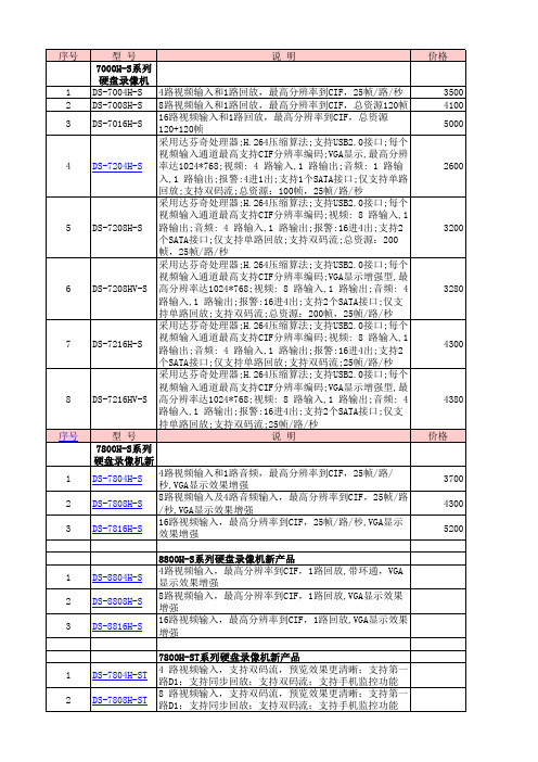

设备硬盘支持型号列表时间:2014-08-25发布出处:海康威视浏览数:54168温馨提示:由于市场上硬盘型号较多,相同型号也可能版本有所不同,我们不可能一一进行测试,敬请见谅!请按照适用型号选择您设备可以支持的硬盘。
分类适用型号80/70-S系列DVR支持硬盘列表DS-8000HF-S, DS-8000HE-S(L), DS-8000HT-S,DS-8000HC-S, DS-8000HC-SL, DS-8000HS-S, DS-8000HS-ST DS-7000H-S, DS-6100HC(-SATA), DS-6100HF(-SATA)81/72/88/78-S系列DVR支持硬盘列表DS-8100HF-S, DS-8100HFS-S, DS-8100HE-ST, DS-8100HE-S, DS-8100HC-S, DS-8100HS-S, DS-8100HL-S,DS-7200HV-S, DS-7200HF-S, DS-7100H-S,DS-7600H-SDS-7800HF-S, DS-8800H-S, DS-7800H-S,DS-6500,DS-7200H-S90/91-S(H)系列DVR/NVR支持硬盘列表DS-9000HF-SH, DS-9000HF-S,DS-9100HF-SH, DS-9100HF-S DS-9600N-SH, DS-9500N-S,DS-7600N-S81-ST、78/72/88-ST(SN/SE)系列支持硬盘列表DS-8100HS-ST, DS-8100HC-ST,DS-8800H-ST,DS-7800HF-ST,DS-7800H-ST/SE/SN,DS-7800HF-SN, DS-7200HV-SN/ST, DS-7200HF-STDS-660081HFS-ST、81HE-ST、73HF-ST支持硬盘列表DS-8100HFS-ST, DS-8100HE-ST, DS-7300HF-ST72/78/79/81/88/73-SH/SNH 系列支持硬盘列表DS-7800H-SNH、DS-7800H-SHT、DS-7800H-SLT、DS-7800HW-SH、DS-7800HF-SH、DS-7200HW-SH、DS-7200HV-SHT、DS-7200HF-SH、DS-72 00HVI-SV、DS-7900HF-SH、DS-7900HW-SH、DS-7900H-SH、DS-7300H W-SH、DS-7300HF-SH、DS-7300HC-SH、DS-7300HI-SH、DS-7300HFI-SH、DS-8100HC-SH、DS-8100HS-SH、DS-8800H-SH、DS-8100HFS-SH、D S-8100HWS-SH、8100HW-EX/C、8100HE-SH、7200HW-EX/C、8800HW-E4、8800HE-E8、8800HW-SH、7900HW-E4、7900HE-E4、7900HW-E4、7 800HW-EX/C、7800HE-E2、DS-7800HW-SNH、DS-7100HC-E1、DS-7100 HW-E1(型号、路数不一样,支持的硬盘型号可能不相同)91/81/90/80HF(H)-ST91HW-ST 96/86/77/76N-ST 支持硬盘列表DS-9100HFH-ST, DS-9100HW-ST, DS-9100HF-ST,DS-9100HF-XTDS-8100HF-ST, DS-8100HW-ST, DS-8100HD-SDS-9000HF-ST,DS-9000HF-XT,DS-8000HF-ST,DS-9600N-ST(包含9664N-ST),DS-9600N-XT(非RAID),DS-8600N-ST(包含8664N-ST),DS-7700N-ST,DS-7700N-SP,DS-7600N-ST,DS-7600N-SP DS-9500N-ST、DS-8500N-STRH系列NVR支持硬盘列表DS-9000HF-RH,DS-9100HF-RH DS-9604/9608/9612/9616N-RH DS-9516N-RRT系列DVR/NVR支持的硬盘列表DS-9000HF-RT,DS-9100HF-RTDS-9600N-RT(包括9664N-RT)、DS-9500N-RTDS-9664N-XT系列支持的硬盘列表DS-9664N-XT DS-9664N-RH支持硬盘列表DS-9664N-RHDS-7600N-SE(/N)(/P)支持硬盘列表DS-7601N-SE, DS-7604/7608N-SE, DS-7604/7608N-SE(/N)DS-7604/7608N-SE(/P)SH/SL系列DVR支持硬盘列表7204HF-SH, 7804HF-SH,7808H-SH,7808H-SL,7816H-SH,7816H-SLDS-96000N-E系列支持硬盘列表DS-96128N-E16、DS-96128N-E16/H、DS-96256N-E16、DS-96256N-E16/H、DS-96128N-E24、DS-96128N-E24/H、DS-96256N-E24、DS-96256N-E24/H76 77 86 N-E1 E2 E2 E8系列支持硬盘列表76xx-Ex、77xx-E4、86xx-E8、78xx-Ex、79xx-Ex、7104N-SL/W系列网络存储设备支持硬盘列表DS-A9, DS-A10, DS-A20, DS-A820, DS-AS10系列IPC支持的存储卡列表海康威视IPC摄像机。
DUAL SURFACE MOUNT SWITCHING DIODEFeatures• Fast Switching Speed • Surface Mount Package Ideally Suited for Automated Insertion • For General Purpose Switching Applications • High Conductance • Lead, Halogen and Antimony Free, RoHS Compliant (Note 3)• "Green" Device (Note 4)Mechanical Data• Case: SOT-23• Case Material: Molded Plastic, “Green” Molding Compound.UL Flammability Classification Rating 94V-0 • Moisture Sensitivity: Level 1 per J-STD-020 • Terminals: Matte Tin Finish annealed over Alloy 42 leadframe(Lead Free Plating) Solderable per MIL-STD-202, Method 208 • Polarity: See Diagram • Marking Information: See Page 2 • Ordering Information: See Page 2 • Weight: 0.008 grams (approximate)Maximum Ratings @T A = 25°C unless otherwise specifiedCharacteristic Symbol Value Unit Peak Repetitive Reverse VoltageWorking Peak Reverse Voltage DC Blocking Voltage V RRM V RWM V R 100 V RMS Reverse Voltage V R(RMS) 71 V Forward Continuous Current (Note 1) I FM300 mA Non-Repetitive Peak Forward Surge Current @ t = 1.0μs@ t = 1.0sI FSM2.0 1.0 AThermal CharacteristicsCharacteristic Symbol Value UnitPower Dissipation (Note 1) P D350 mW Thermal Resistance Junction to Ambient Air (Note 1) R θJA357 °C/W Operating and Storage Temperature Range T J , T STG-65 to +150 °CElectrical Characteristics @T A = 25°C unless otherwise specifiedCharacteristic Symbol Min Max Unit TestConditionReverse Breakdown Voltage (Note 2) V (BR)R 100 ⎯ V I R = 100μAForward Voltage V F 0.55 0.67 0.75 ⎯ 0.700.821.10 1.25 V I F = 1.0mA I F = 10mA I F = 50mAI F = 150mAReverse Current (Note 2) I R ⎯1.03.0 100 25 μA μAμA nA V R = 50V V R = 100V V R = 50V, T J = 125°C V R = 20V Total Capacitance C T⎯ 2.0 pF V R = 0, f = 1.0MHz Reverse Recovery Time t rr ⎯4.0 ns I F = I R = 10mA,I rr = 0.1 x I R , R L = 100ΩNotes:1. Part mounted on FR-4 board with recommended pad layout, which can be found on our website at /datasheets/ap02001.pdf.2. Short duration pulse test used to minimize self-heating effect.3. No purposefully added lead. Halogen and Antimony Free.4. Diodes Inc.'s "Green" policy can be found on our website at ./products/lead_free/index.php.TOP VIEWSOT-23MMBD7000HSMMBD7000HCT , AMBIENT TEMPERATURE (ºC)Fig. 1 Power Derating Curve, T otal PackageA P D , P O W E R D I S S I P A T I O N (m W )1002003004005000.110.010.001I , I N S T A N T A N E O U S F O R W A R D C U R R E N T (A )F V , INSTANTANEOUS FORWARD VOLTAGE (V)Fig. 2 Forward Characteristics, Per Element F1001,000V , INSTANTANEOUS REVERSE VOLTAGE (V)Fig. 3 Typical Reverse Characteristics, Per ElementR I , I N S T A N T A N E O U S R E V E R S E C U R R E N T (n A )R 0.00.20.40.60.81.81.61.41.21.02.0C , T O T A L C A P A C I T A N C E (p F )T V , DC REVERSE VOLTAGE (V)Fig. 4 Total Capacitance vs. Reverse Voltage, Per ElementROrdering Information (Note 5)Part Number Case Packaging MMBD7000HS-7-F SOT-23 3000/Tape & Reel MMBD7000HC-7-FSOT-23 3000/Tape & ReelNotes:5. For packaging details, go to our website at /datasheets/ap02007.pdf.Marking InformationDate Code KeyYear 2009 2010 2011 2012 2013 2014 2015 2016Code W X Y Z A B C DMonth Jan Feb Mar Apr May Jun Jul Aug Sep Oct Nov DecCode 1 2 3 4 5 6 7 8 9 O N Dxxx = Product Type Marking Code: MMBD7000HC = KHC MMBD7000HS = KHS YM = Date Code Marking Y = Year (ex: W = 2009) M = Month (ex: 9 = September) xxx Y MPackage Outline DimensionsSuggested Pad LayoutSOT-23Dim Min Max Typ A 0.37 0.51 0.40 B 1.20 1.40 1.30 C 2.30 2.50 2.40 D 0.89 1.03 0.915 F 0.45 0.60 0.535 G 1.78 2.05 1.83 H 2.80 3.00 2.90 J 0.0130.10 0.05 K 0.903 1.10 1.00 K1 - - 0.400 L 0.45 0.61 0.55 M 0.0850.18 0.11α0° 8°- All Dimensions in mmDimensions Value (in mm)Z2.9 X 0.8 Y 0.9 C 2.0 E 1.35X EYCZIMPORTANT NOTICEDIODES INCORPORATED MAKES NO WARRANTY OF ANY KIND, EXPRESS OR IMPLIED, WITH REGARDS TO THIS DOCUMENT, INCLUDING, BUT NOT LIMITED TO, THE IMPLIED WARRANTIES OF MERCHANTABILITY AND FITNESS FOR A PARTICULAR PURPOSE (AND THEIR EQUIVALENTS UNDER THE LAWS OF ANY JURISDICTION).Diodes Incorporated and its subsidiaries reserve the right to make modifications, enhancements, improvements, corrections or other changes without further notice to this document and any product described herein. Diodes Incorporated does not assume any liability arising out of the application or use of this document or any product described herein; neither does Diodes Incorporated convey any license under its patent or trademark rights, nor the rights of others. Any Customer or user of this document or products described herein in such applications shall assume all risks of such use and will agree to hold Diodes Incorporated and all the companies whose products are represented on Diodes Incorporated website, harmless against all damages.Diodes Incorporated does not warrant or accept any liability whatsoever in respect of any products purchased through unauthorized sales channel. Should Customers purchase or use Diodes Incorporated products for any unintended or unauthorized application, Customers shall indemnify and hold Diodes Incorporated and its representatives harmless against all claims, damages, expenses, and attorney fees arising out of, directly or indirectly, any claim of personal injury or death associated with such unintended or unauthorized application.Products described herein may be covered by one or more United States, international or foreign patents pending. Product names and markings noted herein may also be covered by one or more United States, international or foreign trademarks.LIFE SUPPORTDiodes Incorporated products are specifically not authorized for use as critical components in life support devices or systems without the express written approval of the Chief Executive Officer of Diodes Incorporated. As used herein:A. Life support devices or systems are devices or systems which:1. are intended to implant into the body, or2. support or sustain life and whose failure to perform when properly used in accordance with instructions for use provided in thelabeling can be reasonably expected to result in significant injury to the user.B. A critical component is any component in a life support device or system whose failure to perform can be reasonably expected to cause the failure of the life support device or to affect its safety or effectiveness.Customers represent that they have all necessary expertise in the safety and regulatory ramifications of their life support devices or systems, and acknowledge and agree that they are solely responsible for all legal, regulatory and safety-related requirements concerning their products and any use of Diodes Incorporated products in such safety-critical, life support devices or systems, notwithstanding any devices- or systems-related information or support that may be provided by Diodes Incorporated. Further, Customers must fully indemnify Diodes Incorporated and its representatives against any damages arising out of the use of Diodes Incorporated products in such safety-critical, life support devices or systems.Copyright © 2010, Diodes Incorporated。