土木工程专业外文翻译
- 格式:docx
- 大小:15.22 KB
- 文档页数:1

土木工程专业英语单词Torque 转动扭矩 Impose 施加, 将…强加于Composite 合成的, 复合的Sag 下垂Deflect 偏转, 弯曲, 倾斜Misalignment 安装误差Plaster 灰泥, 灰浆, 涂层Buckling 弯曲, 折曲, 下垂Stiffness 刚度, 刚性 In contradistinction to M 与M截然不同Tension 张力, 拉力 Compression 压缩, 压力Diagrammatic sketch 示意图Ceramics 陶瓷, 陶瓷材料Inertia 惯性 Lifetime 使用寿命Iterative 反复的, 迭代的 Durability 耐久性, 持久性Pinpoint 准确定位, 针尖 Evolve 经过实验研究得出Statics 静力学 Strength of materials 材料力学Deformation 变形Influx 流入, 灌注Distortion 变形Boring machine 镗床Boom 吊杆, 悬臂, 起重杆 Dragline 拉铲挖土级, 挖掘斗Gray cast iron 灰铸铁Modulus of elasticity 弹性模量Rigidity 刚性, 刚度, 稳定性 Slip 滑度, 打滑Creep 蠕变 Yield 屈服于, 屈服Rupture 破裂, 断裂, 破坏 Load-carrying capacity 承载能力Terminology 专用名词 Helical spring 螺旋型弹簧Concentrated 集中的, 浓缩的 Distribute 分布, 分发, 散布Resultant 合力, 合成的 Centroid 矩心, 重心Torsional 扭的, 转的Bending 挠曲, 弯曲Flexural 弯曲的, 挠性的 couple 对, 双, 力偶Non-load-bearing 非承重 brittle 脆弱的, 脆性的ASTM 美国材料试验学会BSI 英国标准学会SAA 澳大利亚标准学会 Passage 一段, 一节Plastic deformation 塑性变形moisture content 含水量Timber 木材 veracity 诚实, 真实性Ready-mixed concrete 预拌混凝土building contractor 建筑承包商Hydraulic press 水压机 grading 分等, 分类, 级配Fatigue 疲劳ductility 可延展性Toughness 韧性 stress-strain curve 应力-应变曲线Durability 耐久性, 耐用年限 chloride 氯化物, 漂白粉Sulphate 硫酸盐alkali 碱性, 碱Permeability 渗透性, 透气性 weathering 风化Disruptive 分裂的, 摧毁的 thaw 融化, 解冻Entrain 携带, 传输 leaching 浸出, 溶析Carbonation 炭化作用blasting 破裂, 吹风Attrition 磨损 cavity 洞穴Hydraulic structure 水工建筑物 pervious 透水的, 透光的Aggregate 集料, 骨料 homogeneous 均质的, 均匀的Compact 压实, 捣紧 kerb 路缘, 道牙Air-entrained concrete 加气混凝土 glaze 珐琅质, 上釉Stainless steel 不锈钢galvanize 电镀Gutter 排水沟, 楼都不 humidity 湿度, 湿气Porous 多孔的, 疏松的 spectrum 谱Infrared 红外的, 产生红外辐射的 ultraviolet 紫外的Gravel 砾石, 卵石 anodized 受过阳极化处理的Hydrate 水合物reinforcement 加强, 加固Spall 剥落, 散裂 erosion 侵蚀, 腐蚀Abrasion 磨损, 磨耗 quarry 方形砖Eddy 涡流, 漩涡运动 reinforcing steel 钢筋Reinforced concrete 钢筋混凝土 reinforcing bar 钢筋Longitudinal 长度的, 纵向的, 轴向的 dispose 处置Incline 倾斜, 弄斜 moment 力矩Bond 结合, 结合力, 粘合力 interlock 连动, 连接Forestall 阻止, 预防 embed 放入, 埋入Prestressing steel 预应力钢筋 rebar 钢筋Splice 接头 congestion 充满Form 模坂 ACI 美国混凝土协会Code 法规, 规程 galvanize 电镀Undue 过度的, 过分的 BS 英国标准Blending machine 弯筋机mandrel 芯棒Jig 夹具 dowel 夹缝丁, 暗销Wire clip 钢丝剪reference number 参考号数Mill scale 热轧钢表面氧化皮spacer 隔离物Clip 夹子, 剪刀slab 板, 块, 楼板Cradle 吊架, 托架, 支架chair 托架, 支板Mild steel 低碳钢 tack 图钉, 点焊焊缝Hydraulic 水力的, 液力的 additive 添加剂Admixture 外加剂 binder 胶结剂Aggregate 聚集, 结合, 骨料, 填料aerate 充气Aerate concrete 加气混凝土cellular 蜂窝状的Portland 波特兰水泥 pulverize 粉化, 磨碎Granulate 成粒状, 轧碎 blastfurnace 高炉, 鼓风炉Slag 矿渣, 炉渣 pigment 颜料, 色料Retarder 延迟剂, 缓凝剂accelerator 加速剂, 促凝剂Curing (混凝土)养护compaction 压实, 捣实Ambient 周围的, 外界的shrinkage 收缩, 下沉, 压缩Autoclave 蒸压器, 热压处理 frost 粗糙的, 无光泽的Efflorescence 风化, 粉化, 粉化物 sodium 钠Calcium 钙potassium 钾Carbonate 炭化 pozzolana 火山灰Sulphate 硫酸盐autoclaved aerated concrete 高压蒸养加气混凝土Hard-burnt 高温焙烧的, 炼制的 veneer 镶片, 砌面, 表层Mallet 木锤, 大锤 chisel 凿子Mold 模子, 模具mass production 大量生产Update 使现代化trade journal 行业杂志Periodical 定期的, 定期刊行的 editorial board 编辑委员会Beholder 旁观者 ordinance 规格, 条例, 法令Suspended structure 悬吊结构 joist 梁, 垳条Through bridge 下承桥 chord 弦杆Bracing 拉条, 支撑 web-girder 腹板大梁Box-girder 箱梁 plan view 平面图Outline 外形, 剖面 drawing 附图Bills of materials 材料清单radiator 散热器General arrangement 总体布置detail drawing 详图Cladding 包层, 包壳 panel 面板, 仪表盘GA drawing 总体平面图 zoom 变焦距In situ 原地, 在原地cumbersome 笨重的, 麻烦的Parameterized 参数化 specification 详细说明, 规范Verify 校验, 验证, 说明homogeneous 均匀的, 对等的Buckling 弯曲, 翘曲, 弯折 deterministic 确定的, 决定的Probabilistic 概率的, 随机的 deviation 偏差, 偏移, 参数Psychological 心理的, 精神的 cross-section 横断面, 横截面Amortization 阻尼 proof-load 检验荷载Field 场地, 工地survey 调查, 测量, 勘察Intrinsic 内在的, 固有的 stochastic 随机的, 不确定的Seismic 地震的, 与地震有关的 single load 集中荷载Foundation 基础, 地基gravity 重力Lateral 横向的, 侧面的 transient 瞬时的, 不稳定的Basement 底座, 基础, 地下室 erratic 反复无常的, 无规律的Footing 基础, 基脚, 底座, 垫层overdesign 保险设计Underdesign 欠安全设计 appurtenance 附属物, 附属设备Firewall 防火墙parapet 栏杆, 护墙, 女儿墙Remold 改造, 改型, 重铸 ductwork 管道系统, 管网Tenant 租用 latitude 纬度, 宽度, 范围Tributary 支流, 附庸, 辅助的cantilever 悬臂, 悬臂梁, 支架Provision 预防, 规定, 条款 overload 超载, 超重Reference 参考书 uncertainty 不确定性Slighting 轻蔑的, 不尊重的 likelihood 像有, 相似Pef = pounds per cubic foot 磅/平方英尺reliability 可靠性, 安全性Methodology 方法论 shield 屏蔽Shield 屏蔽, 遮护 without recourse to 不依赖Reason 推理, 论证 weir 堰, 拦河堰Spillway 溢洪道, 泻水道clause 条款项目Deploy 适用, 配置 filler wall 填充墙, 柱间墙Shear wall 剪力墙ignorance 外行Up-to-date 现代的, 最新likewise 同样Bucket 吊斗, 挖斗 wheelarrow 手推车, 独轮小车Buggy 手推车, 小斗车segregation 分凝, 离析Chute 斜槽 place 场所, 浇筑Lift 混凝土浇筑层, , 升降机displacement 偏移Compact 夯实 honeycomb 蜂窝结构Tamping 夯实, 捣固, 捣实 spinkling 喷洒Calcium chloride 氯化钙 settlement 沉陷Grout 水浆, 灌浆cohesive 粘聚的, 粘结的Workable 和易性好的,塑性的slump 坍塌度Workability 可塑性 air-entraining 加气的Deposit 存储, 浇注consolidation 加固, 压实Bleeding 渗漏subsidence 沉降, 下降Laitance 水泥浮浆 float 镘刀, 抹子Capillary 毛细管的, 毛细现象 flash set 急凝Aluminate 铝酸盐 burlap 麻袋, 粗麻布Membrane 膜, 隔板 emulsion 乳胶体, 乳液Polyethylene 聚乙烯 waterproof 防水Harden 硬化, 凝固 gravel 砾石, 卵石Immersion 浸入, 插入 headroom 净空高度, 头上空间Nominal 铭牌的, 名义的 power-driven 动力驱动的, 电动的External vibrator 表面振捣器 architect 建筑师Nonhomogeneous 不均匀的, 多相的creep 蠕变Shrink 缩小structure code 结构规范Ultimate strength 极限强度 load factor 荷载系数From M onwards 从m算起来 prestressed concrete 预应力混凝土Faulty 有缺点的, 报废的, 不合格的 embed 放入, 埋入Abutment 桥台,岸墩 thrust 推, 轴向力Jack 千斤顶, 支柱 motorway 汽车道, 快车道Tendon 钢筋束, 筋post-tensioned prestressing 后张法预应力Pre-tensioned prestressing 先张法预应力 manoeuvrable 机动的, 容易驾驶的Plain concrete 无筋混凝土 precompression 预加压力, 预先压缩Leak 漏, 渗漏camber 弯度, 曲度, 凸形Proportioning 使成比例, 确定几何尺寸 analogous 类似的, 类比的, 模拟的With reference to 参考, 参照, 关于centroid 矩心, 面积矩心, 质心Refinement 精制, 改善, 改进 bond 结合, 粘合, 粘合强度Transmit 传递, 寄, 传送 interlocking 可联动的, 联锁Plain bar 光面钢筋, 无结钢筋 formed bar 变形钢筋, 竹结钢筋Hoop 环, 箍, 铁箍tie 拉杆, 系杆Stirrup 箍筋, 钢筋箍 crushing 压碎, 轧碎Bearing 承载, 承受, 支撑点 bearing pressure 支承压力Rib 肋, 棱, perimeter 周边, 周长, 周界Blanketing 覆盖, 包上, 掩盖 mortar 砂浆, 灰浆, 灰泥Bentonite 膨润土, 膨土岩 trench 沟槽, 沟道, 沟管Tremie 混凝土导管(水下浇筑用) full prestressing 全预应力Partial prestressing 部分预应力reservoir 水库, 蓄水池Eccentric 偏心的, 呈偏心运动的, 偏心器 counteract 中和, 平衡Intermitterntly 间隙的, 断续的, 周期的 infrequent 不常见的, 稀少的Objectionable 不能采用的, 不适宜的reverse 颠倒的, 改变方向的, 交换的Cement paste 水泥浆sack 袋, 包, 一包, 一袋Water-cement ratio 水灰比trial-batch (混凝土)小量试拌Slump test 坍塌度试验 truncate 缩短, 截去Air-entraining agent 加气剂 plasticizer 增塑剂, 塑化剂revolving-drum mixer 转筒式搅拌机 ready-mixed 运送时搅拌的transit0mixed 运送时拌的 batch 配料, 分批配料congested 拥挤的, 充塞的 haul 搬运, 运输discharge 卸货, 卸载 hopper 漏斗, 装料车batching plant 拌和厂 batching 配料, 定配合比ecclesiastical 基督教会的, 教士的 landmark 陆标, 里程碑, 界标mobility 可动性, 机动性, 流动性 topographical 地形的, 地形测量的subservient 辅助性的tax 使受压力, 负担shear wall core 剪力墙筒体 prefabrication 预制的, 预制品slip-formwork 滑模 crane 起重机, 用起重机吊codify 编成法典, 编纂 elevator 升降机escalator 升降梯, 自动扶梯drift 漂移, 位移prescribe 规定, 命令, 指示I-beam 工字梁, 工字钢masonry 砖石工程, 砌筑体staircase 楼梯lofty 高耸的, 极高的condominium 各住户认购各自一套公寓楼brace 支撑, 支柱bundle 捆, 扎, 粘合soaring 高耸的, 高涨的 tributary 支流, 从属的prototype 原型, 样机web 腹板, 梁板torsion 扭转, 转矩 orthogonal 互相垂直的, 正交的, 直角的stiffen 加强, 加固 urbanization 都市化habitation 住宅, 住所deterrent 制止物, 威慑因素premium 奖金, 质量改进的clutter 混乱, 干扰, 弄乱multi-discipline 多学科pedestrian 行人, 步行者plaza 广场, 大空地sway 摇, 摆动overturn 倾倒, 翻转 clear span 净高clear spacing 净距 zoning 分区, 区域化excavation 挖掘, 挖方 overlook 检查, 监督interim 间歇底, 暂时的empiricism 经验主义elastoplastic 弹塑性的subset 子系统compartmentalize 间隔化,隔开,分段 mantle 罩,外壳,地幔erosion 侵蚀,冲刷,磨损 waterborne 水生的,水力运输的boulder 漂砾,大块石 cobble 圆石,鹅软石pebble 小软石,小砾石 degradation 剥蚀,退化avalanche 山崩,坍方,崩塌 stratum 地层,岩层meandering 曲折的,弯曲的,曲流的 stratified 有层次的,分层的water table 地下水位 detritus 瓦砾,腐质percolation 渗透,渗滤 soil profile 土壤剖面,土层剖面residual soil 残积土transported soil 运积土ground water 地下水superstructure 上层结构earth fill 土堤substructure 下部结构,基础工事demarcation 分界线 sanitary 环境卫生的sanitary fill 垃圾堆积场reclamation 废料回收,改造,垦殖disposal 处理,清理,处置boring 钻探,打眼mat 席,垫,钢筋网 caisson 沉箱retaining-wall 挡土墙uneven settlement 不均匀沉降overburden 超载,过载 strap beam 搭扣形梁unsound 不坚固的,不牢固的pile 桩,打桩hardpan 硬土层,坚固基础 raft 筏,木排combined footing 联合基础 cantilever footing 悬臂基础raft of floating foundation 筏式基础或浮筏基础soil mass 土体pile shaft 桩身 stratum 地层, 矿层end-bearing pile 端承桩 uplift 举起, 抬起water table 地下水位scour 冲刷, 洗涤deposit 沉积, 浇注, 矿床 soil-exploration 土质勘察footing 基础, 基脚, 底座 strip 带, 条, 狭长片raft 筏, 垫板 capital 柱头fixity 固定, 不变eccentric 偏心的, 不同圆心的nonuniformity 不均匀性, 不均质性 scheduling 编制时间表drain 消耗, 耗尽premium 奖金, 佣金hold up 阻碍procurement 取得, 获得, 采购vector 矢量, 向量prerequisite 先决条件, 前提concurrent 同时进行的, 并行的 lead time 产品设计至实际投产时间litigation 诉讼, 打官司 chronological 按时间顺序的hoist 卷扬机, 起重机 utility 实用的, 公用事业utility line 公用事业管线 accrue 产生, 出现dismantle 拆除, 拆卸 remuneration 酬劳, 报酬commensurate 同量的, 相应的 degenerate into 简化成, 变质成in-house 机构内部的 critical path 关键路径lay down 规定, 制定计划 wearing surface 磨耗面base course 基层 asphalt 柏油landscaping 风景设计, 风景布置 bulldozer 推土机, 压路机vibrating roller 振动压路机 bitumen 沥青grill 格栅, 铁格网mesh 网, 网格, 筛concrete train 混凝土铺路机组 slipform paver 滑模铺路机hold in place 把…固定在引诱的位置runway 跑道, 通道Tokaido line 新干线 catalyst 触媒, 催化剂Side-effect 副作用 decentralization 分散, 疏散Unity 整体, 单元 outstrip 超过Crude 天然的, 原油piecemeal 片断, 点Ferment 酵素, 发酵, 蓬勃发展 underlying 基础的, 根本的Geographer 地理学家 operations research 运筹学Cable-stayed 斜拉的, 张拉的 girder 梁, 垳, 梁杆Cast-in-place 现场浇筑的 AASHT美国洲际公路及运输工作者协会AREA 美国铁路工程师协会 crossing 交叉, 十字路口Pier 桥墩 elevated 高架的, 高的, 高架铁路Clearance 间隙, 净空, 间距 segment 部分, 段Dominance 支配, 控制, 优势 one-way slab 单向配筋板Versus 与…的关系曲线 statically determinate structure 静定结构Skew 斜的, 扭的, 弯曲的on-site 现场的, 就地的, 工地Shear key 受剪键bituminous concrete 沥青混凝土Dissipate 清除, 消除 composite structure 混合结构Acronym 缩写词, 缩语chore 零星工作, 零活In the foreseeable future 在可遇见的未来一段时间内 impetus 动力, 刺激Draughtsman 绘图员, 起草者 repetitious 重复的, 反复的Mundane 世间的, 世俗的jargon 行话, 术语, 难懂的话Level 水平, 水位, 水平仪 theodolite 精密经纬仪Envision 想象, 遇见, 展望contour map 等高线, 地形图Plat 地段, 地区图, 地段图grading 校准, 定标, 土工修正Stake 标桩, 定位木桩picture 图画, 设想, 想象Cut 挖土, 挖方 fill 填筑, 填方, 填土, 路堤Borrow 取土, 采料, 采料场 indeterminate structure 超静定结构Myriad 万, 无数, 无数的 photogrammetry 摄影测绘sGeotechnical engineering 岩土工程 mass transit 公共交通Transmission line 输电线infiltrate 渗入, 渗透Estimator 估价者, 评价者rival 对手, 竞争, 比得上Off-the-shelf 现成的, 成品的, 畅销的 afterthought 回想, 反省, 后悔, 马后炮Timeliness 及时, 时间性, 好时机 inception 开始, 起头, 开端Culminate 达到顶点, 结束 beneficiary 受益人, 受惠人Outset 开始, 最初 working drawing 施工图Prescribe 规定, 命令 delineation 描绘, 描述Co-ordinate 相同, 同等的事物 prerogative 特权, 特性Board of directors 董事会 estimating 估价Margin 边缘, 余量, 余地tender 投标, 承包, 标件Incisive 尖锐的, 深刻的, 透彻的 realm 范围, 部门, 类Forethought 预先考虑好的modus 方法, 程式Modus operandi 做法, 方法, 工作方式nullify 废弃, 取消Indispensable 不可缺少的, 必需的 corollary 推论, 结果Doom 毁灭, 灭亡, 判决 obverse 较显著面Tactical 战术的, 策略的deployment 部署, 调度, 配置Ensemble 整体, 总效果 pictorial 绘图的, 插图的Dispassionate 冷静的, 不带偏见的 prognosis 预测, 预报Ubiquitous 普遍存在的, 随遇的 denominator 分母, 标准Handmaiden 起陪衬作用的 liken 比拟Jobbing 做临时工trade journal 行业期刊Cost plus 附加费 premise 前提, 房产Speculation 投机, 投机买卖sub-contractor 转包商, 分包商Order 订单 on-cost 杂费, 间接成本Microfiche 缩微胶片, 平片。

土木工程专业英语
土木工程专业英语 abandon v.放弃
abbreviation n.缩写
abrasion n.擦伤,磨损
abundance a.丰富,充裕,大量 access road 入口
accessibility n.可大性,可接近性 acid corrode 酸性腐蚀
acre n.英亩
acronym n.简称,只取首字母的缩写词 adapter n.适配器,转换接头,附件admeasurement contract 计价合同 admixture n.掺和剂
adverse a.不利的
aerodynamic a.空气动力的
aggregate n.骨料,集料
reactive aggregate 活性骨料
agitation n.拌和
air conditioning 空气调节
air-entrained concrete 加气混凝土 akin a.类似的,同样的(常跟to连用) alcove n.凹室,壁龛
alkaline a.碱性(的) high-alkai a.高碱性的
allocate v.分配,分派,配给 allowable stress 允许应力
allowable stress approach 允许应力法 allowance n.留量,容差,补助alkali-aggregate reaction 碱-骨料反应 alternative n.比较方案 a.交替的,变更的,比较的
aluminum(aluminium) n.铝
aluminium alloy 铝合金
amalgam n.混合物,软的混合物 amenity n.舒适,适宜,愉快 analogous a。

外文原文:Civil EngineeringCivil engineering is the planning, design, construction, and management of the built environment. This environment includes all structures built according to scientific principles, from irrigation and drainage systems to rocket launching facilities.Civil engineers build roads, bridges, tunnels, dams, harbors, power plants, water and sewage systems, hospitals, schools, mass transit, and other public facilities essential to modern society and large population concentrations. They also build privately owned facilities such as airport, railroads, pipelines, skyscrapers, and other large structures designed for industrial, commercial, or residential use. In addition, civil engineers plan, design, and build complete cities and towns, and more recently have been planning and designing space platforms to self-contained communities.The word civil derives from the Latin for citizen. In 1782, Englishman John Seaton used the term to differentiate his nonmilitary engineering work from that of the military engineers who predominated at the time. Since then, the term civil engineer has often been used to refer to engineers who build public facilities, although the field is much broader.Scope Because it is so broad, civil engineering is subdivided into a number of technical specialties. Depending on the type of project, the skills pf many kinds of civil engineer specialties may be needed. When a project begins, the site is surveyed and mapped by civil engineers who experiment to determine if the earth can bear the weight of project. Environmental specialists study the project’s impact on the local area, the potential for air and groundwater pollution, the project’s impact on local animal and plant life, and how the project can be designed to meet government requirements aimed at protecting the environment. Transportation specialists determine what kind of facilities are needed to ease the burden on local roads and other transportation networks that will result from the completed project. Meanwhile, structural specialists raise preliminary data to make detailed designs, plans, and specifications for the project. Supervising and coordinating the work of these civil engineer specialists, from beginning to end of the project, are the construction management specialists. Based on information supplied by the other specialists, construction management civil engineers estimate quantitiesand costs of materials and subcontractors, and perform other supervisory work to ensure the project is completed on time and as specified.Many civil engineers, among them the top people in the field, work in design. As we have seen, civil engineers work on many different kinds of structures, so it is normal practice for an engineer to specialize in just one kind. In designing buildings, engineers often work as consultants to architectural or construction firms. Dams, bridges, water supply systems, and other large projects ordinarily employ several engineers whose work is coordinated by a system engineer who is in charge of the entire project. In many cases, engineers from other disciplines are involved. In a dam project, for example, electrical and mechanical engineers work on the design of the powerhouse and its equipment. In other cases, civil engineers are assigned to work on a project in another field; in the space program, for instance, civil engineers were necessary in the design and construction of such structures as launching pads and rocket storage facilities.Throughout any given project, civil engineers make extensive use of computers. Computes are used to design the project’s various elements (computer-aided design, or CAD) and to manger it. Computers are a necessity for the modern civil engineer because they permit the engineer to efficiently handle the large quantities of data needed in determining the best way to construct a project.Structural engineering In this specialty, civil engineers plan and design structures of all types, including bridges dams, power plants, supports for equipment, special structures for offshore projects, the United States space program, transmission towers, giant astronomical and radio telescopes, and many other kinds of projects.Using computers, structural engineers determine the forces a structure must resist, its own weight, wind and hurricane forces temperature changes that expand or contract construction materials, and earthquakes. They also determine the combination of appropriate materials: steel, concrete, plastic, stone, asphalt, brick, aluminum, or other construction materials.Water resources engineering Civil engineers in this specialty deal with all aspects of the physical control of water. Their projects help prevent floods, supply water for cities and for irrigation, manage and control rivers and water runoff, and maintain beaches and other waterfront facilities. In addition, they design and maintain harbors, canals, and locks, build huge hydroelectric dams and smaller dams and water impoundments of all kinds, help design offshorestructures, and determine the location of structures affecting navigation.Geotechnical engineering Civil engineers who specialize in this filed analyze the properties of soils and rocks that support structures and affect structural behavior. They evaluate and work to minimize the potential settlement of buildings and other structures that stems from the pressure of their weight on the earth. These engineers also evaluate and determine how to strengthen the stability of slopes and how to protect structures against earthquakes and the effects of groundwater.Environmental engineering In this branch of engineering, civil engineers design, build, and supervise systems to provide safe drinking water and to prevent and control pollution of water supplies, both on the surface and underground. They also design, build, and supervise projects to control or eliminate pollution of the land and air. These engineers build water and wastewaters treatment plants, and design air scrubbers and other devices to minimize or eliminate air pollution caused by industrial processes, incineration, or other smoke-producing activities. They also work to control toxic and hazardous wastes through the construction of special dump sites or the neutralizing of toxic and hazardous substances. In addition the engineers design and manage sanitary landfills to prevent pollution of surrounding land.Transportation engineering Civil engineers working in this specialty build facilities to ensure safe and efficient movement of both people and goods. They specialize in designing and maintaining all types of transportation facilities, highways and streets, mass transit systems, railroads and airfields ports and harbors. Transportation engineers apply technological knowledge as well as consideration of the economic, political, and social factors in designing each project. They work closely with urban planners since the quality of the community is directly related to the quality of the transportation system.Pipeline engineering In this branch of civil engineering, engineers build pipelines and related facilities, which transport liquids, gases, or solids ranging from coal slurries (mixed coal and water) and semi liquids wastes, to water, oil and various types pf highly combustible and noncombustible gases. The engineers determine pipeline design, the economic and environmental impact of a project on regions it must traverse, the type pf materials to be used-steel, concrete, plastic, or combinations of various materials, installation techniques, methods for testing pipeline strength, and controls for maintaining proper pressure and rate of flow of materials being transported. When hazardous materials are being carried, safety is a major consideration as well.Construction engineering Civil engineers in this field oversee the construction of a project from beginning to end. Sometimes called project engineers, they apply both technical and managerial skills, including knowledge of construction methods, planning, organizing, financing, and operating construction projects. They coordinate the activities of virtually everyone engaged in the work: the surveyors, workers who lay out and construct the temporary roads and ramps, excavate for the foundation, build the forms and pour the concrete; and workers who build the steel frame-work. These engineers also make regular progress reports to the owners of the structure.Construction is a complicated process on almost all engineering projects. It involves scheduling the work and utilizing the equipment and the materials so that coats are kept as low as possible. Safety factor must also be taken into account, since construction can be very dangerous. Many civil engineers therefore specialize in the construction phase.Community and urban planning Those engaged in this area of civil engineering may plan and develop communities within a city, or entire cities. Such planning involves far more than engineering considerations; environmental, social, and economic factors in the use and development of land and natural resources are also key elements. They evaluate the kinds of facilities needed, including streets and highways, public transportation systems, airports, and recreational and other facilities to ensure social and economic as well as environmental well-being.Photogrammetry, surveying, and mapping The civil engineers in this specialty precisely measure the Earth’s surface to obtain reliable information for locating and designing engineering projects. This practice often involves high-technology methods such as satellite and aerial surveying, and computer processing of photographic imagery. Radio signals from satellites, scanned by laser and sonic beams, are converted to maps to provide very accurate measurements for boring tunnels, building highways and dams, plotting flood control and irrigation projects, locating subsurface geologic formations that may affect a construction project and a host of other building uses.Other specialties Three additional civil engineering specialties that are not entirely within the scope of civil engineering teaching.Engineering research Research is one of the most important aspects of scientific and engineering practice. A researcher usually works as a member of a team with other scientists and engineers. He or she is often employed in alaboratory that financed by government or industry. Areas of research connected with civil engineering include soil mechanics and soil stabilization techniques, and also the development and testing of new structural materials.Engineering management Many civil engineers choose careers that eventually lead to management. Others are also to start their careers in management positions. The civil engineer manager combines technical knowledge with an ability to organize and coordinate worker power, materials, machinery, and money. These engineers may work in government municipal, county, state, or federal; in the U.S.Army Corps of Engineers as military or civilian management engineers; or in semiautonomous regional or city authorities or similar organization. They may also manage private engineering firms ranging in size from a few employees to hundreds.Engineering teaching The civil engineer who chooses a teaching career usually teaches both graduate and undergraduate students in technical specialties. Many teaching civil engineers engage in basic research that eventually leads to technical innovations in construction materials and methods. Many also serve as consultants on engineering projects, or on technical boards and commissions associated with major projects.中文译文:土木工程土木工程是指对建成环境的规划、设计、建造、管理等一系列活动。

(1)Concrete and reinforced concrete are used as building materials in every country. In many, including Canada and the United States, reinforced concrete is a dominant structural material in engineered construction.(1)混凝土和钢筋混凝土在每个国家都被用作建筑材料。
在许多国家,包括加拿大和美国,钢筋混凝土是一种主要的工程结构材料。
(2)The universal nature of reinforced concrete construction stems from the wide availability of reinforcing bars and the constituents of concrete, gravel, sand, and cement, the relatively simple skills required in concrete construction.(2) 钢筋混凝土建筑的广泛存在是由于钢筋和制造混凝土的材料,包括石子,沙,水泥等,可以通过多种途径方便的得到,同时兴建混凝土建筑时所需要的技术也相对简单。
(3)Concrete and reinforced concrete are used in bridges, building of all sorts, underground structures, water tanks, television towers, offshore oil exploration and production structures, dams, and even in ships.(3)混凝土和钢筋混凝土被应用于桥梁,各种形式的建筑,地下结构,蓄水池,电视塔,海上石油平台,以及工业建筑,大坝,甚至船舶等。

1.Central iron & Steel Research institute, Beijing 100081, China2.Chinese Society for Metals, Beijing 100711, China高层建筑与钢结构HUi Wei-jun,DONG HanWENG Yu-ging,CHEN Si-lian,WANG Mao-giu摘要耐火钢其实就是对火灾有一定抵抗能力的钢材,日本认为耐火钢是焊接结构用轧制钢材的一类,在我国它是建筑用低合金钢的一种。
耐火钢于普通的建筑用钢不同,它要求具有良好的耐高温性能,作为常温下的承载材料,只要求在遇到火灾的较短时间内(1到3小时)高温条件下能够保持高的屈服强度,常温下钢材强度的2/3相当于该材料的长期允许应力值,当发生火灾时,如果耐火钢的屈服点仍然在此值以上,建筑物就不会倒塌。
因此,就要求耐火钢在一定高温下的屈服不低于室温下屈服强度的2/3。
本文研究的目的在于研究提高耐火港的强韧性、抗震性和耐火性能。
关键字高层建筑;钢结构;发展应用1.前言近年来,虽然一般的建筑结构设计取得了很大的进步,但是取得显著成绩的还要数超高层建筑结构设计。
最初的高层建筑设计是从钢结构的设计开始的。
钢筋混凝土和受力外包钢筒系统运用起来是比较经济的系统,被有效地运用于大批的民用建筑和商业建筑中。
50层到100层的建筑被成为超高层建筑。
而这种建筑在美国被广泛的应用是由于新的结构系统的发展和创新。
这样的高度需要大柱和梁的尺寸,这样以来可以使建筑物更加坚固以至于在允许的限度范围内承受风荷载而不产生弯曲和倾斜。
过分的倾斜会导致建筑物的隔离构件、顶棚以及其它建筑细部产生循环破坏。
除此之外,过大的摇动也会使建筑物的使用者感觉到这样的晃动而产生不舒服的感觉。
无论是钢筋混凝土结构系统还是钢结构系统都充分利用了整个建筑的刚度潜力,因此,不能指望利用多余的刚度来限制侧向位移。

土木工程专业外语词汇大全中英翻译1. 综合类大地工程geotechnical engineering1. 综合类反分析法back analysis method1. 综合类基础工程foundation engineering1. 综合类临界状态土力学critical state soil mechanics1. 综合类数值岩土力学numerical geomechanics1. 综合类土soil, earth1. 综合类土动力学soil dynamics1. 综合类土力学soil mechanics1. 综合类岩土工程geotechnical engineering1. 综合类应力路径stress path1. 综合类应力路径法stress path method2. 工程地质及勘察变质岩metamorphic rock2. 工程地质及勘察标准冻深standard frost penetration2. 工程地质及勘察冰川沉积glacial deposit2. 工程地质及勘察冰积层(台)glacial deposit2. 工程地质及勘察残积土eluvial soil, residual soil2. 工程地质及勘察层理beding2. 工程地质及勘察长石feldspar2. 工程地质及勘察沉积岩sedimentary rock2. 工程地质及勘察承压水confined water2. 工程地质及勘察次生矿物secondary mineral2. 工程地质及勘察地质年代geological age2. 工程地质及勘察地质图geological map2. 工程地质及勘察地下水groundwater2. 工程地质及勘察断层fault2. 工程地质及勘察断裂构造fracture structure2. 工程地质及勘察工程地质勘察engineering geological exploration 2. 工程地质及勘察海积层(台)marine deposit2. 工程地质及勘察海相沉积marine deposit2. 工程地质及勘察花岗岩granite2. 工程地质及勘察滑坡landslide2. 工程地质及勘察化石fossil2. 工程地质及勘察化学沉积岩chemical sedimentary rock2. 工程地质及勘察阶地terrace2. 工程地质及勘察节理joint2. 工程地质及勘察解理cleavage2. 工程地质及勘察喀斯特karst2. 工程地质及勘察矿物硬度hardness of minerals2. 工程地质及勘察砾岩conglomerate2. 工程地质及勘察流滑flow slide2. 工程地质及勘察陆相沉积continental sedimentation2. 工程地质及勘察泥石流mud flow, debris flow2. 工程地质及勘察年粘土矿物clay minerals2. 工程地质及勘察凝灰岩tuff2. 工程地质及勘察牛轭湖ox-bow lake2. 工程地质及勘察浅成岩hypabyssal rock2. 工程地质及勘察潜水ground water2. 工程地质及勘察侵入岩intrusive rock2. 工程地质及勘察取土器geotome2. 工程地质及勘察砂岩sandstone2. 工程地质及勘察砂嘴spit, sand spit2. 工程地质及勘察山岩压力rock pressure2. 工程地质及勘察深成岩plutionic rock2. 工程地质及勘察石灰岩limestone2. 工程地质及勘察石英quartz2. 工程地质及勘察松散堆积物rickle2. 工程地质及勘察围限地下水(台)confined ground water 2. 工程地质及勘察泻湖lagoon2. 工程地质及勘察岩爆rock burst2. 工程地质及勘察岩层产状attitude of rock2. 工程地质及勘察岩浆岩magmatic rock, igneous rock2. 工程地质及勘察岩脉dike, dgke2. 工程地质及勘察岩石风化程度degree of rock weathering 2. 工程地质及勘察岩石构造structure of rock2. 工程地质及勘察岩石结构texture of rock2. 工程地质及勘察岩体rock mass2. 工程地质及勘察页岩shale2. 工程地质及勘察原生矿物primary mineral2. 工程地质及勘察云母mica2. 工程地质及勘察造岩矿物rock-forming mineral2. 工程地质及勘察褶皱fold, folding2. 工程地质及勘察钻孔柱状图bore hole columnar section3. 土的分类饱和土saturated soil3. 土的分类超固结土overconsolidated soil3. 土的分类冲填土dredger fill3. 土的分类充重塑土3. 土的分类冻土frozen soil, tjaele3. 土的分类非饱和土unsaturated soil3. 土的分类分散性土dispersive soil3. 土的分类粉土silt, mo3. 土的分类粉质粘土silty clay3. 土的分类高岭石kaolinite3. 土的分类过压密土(台)overconsolidated soil3. 土的分类红粘土red clay, adamic earth3. 土的分类黄土loess, huangtu(China)3. 土的分类蒙脱石montmorillonite3. 土的分类泥炭peat, bog muck3. 土的分类年粘土clay3. 土的分类年粘性土cohesive soil, clayey soil3. 土的分类膨胀土expansive soil, swelling soil3. 土的分类欠固结粘土underconsolidated soil3. 土的分类区域性土zonal soil3. 土的分类人工填土fill, artificial soil3. 土的分类软粘土soft clay, mildclay, mickle3. 土的分类砂土sand3. 土的分类湿陷性黄土collapsible loess, slumping loess3. 土的分类素填土plain fill3. 土的分类塑性图plasticity chart3. 土的分类碎石土stone, break stone, broken stone, channery, chat, crushed stone, deritus 3. 土的分类未压密土(台)underconsolidated clay3. 土的分类无粘性土cohesionless soil, frictional soil, non-cohesive soil3. 土的分类岩石rock3. 土的分类伊利土illite3. 土的分类有机质土organic soil3. 土的分类淤泥muck, gyttja, mire, slush3. 土的分类淤泥质土mucky soil3. 土的分类原状土undisturbed soil3. 土的分类杂填土miscellaneous fill3. 土的分类正常固结土normally consolidated soil3. 土的分类正常压密土(台)normally consolidated soil3. 土的分类自重湿陷性黄土self weight collapse loess4. 土的物理性质阿太堡界限Atterberg limits4. 土的物理性质饱和度degree of saturation4. 土的物理性质饱和密度saturated density4. 土的物理性质饱和重度saturated unit weight4. 土的物理性质比重specific gravity4. 土的物理性质稠度consistency4. 土的物理性质不均匀系数coefficient of uniformity, uniformity coefficient4. 土的物理性质触变thixotropy4. 土的物理性质单粒结构single-grained structure4. 土的物理性质蜂窝结构honeycomb structure4. 土的物理性质干重度dry unit weight4. 土的物理性质干密度dry density4. 土的物理性质塑性指数plasticity index4. 土的物理性质含水量water content, moisture content4. 土的物理性质活性指数4. 土的物理性质级配gradation, grading4. 土的物理性质结合水bound water, combined water, held water4. 土的物理性质界限含水量Atterberg limits4. 土的物理性质颗粒级配particle size distribution of soils, mechanical composition of soil 4. 土的物理性质可塑性plasticity4. 土的物理性质孔隙比void ratio4. 土的物理性质孔隙率porosity4. 土的物理性质粒度granularity, grainness, grainage4. 土的物理性质粒组fraction, size fraction4. 土的物理性质毛细管水capillary water4. 土的物理性质密度density4. 土的物理性质密实度compactionness4. 土的物理性质年粘性土的灵敏度sensitivity of cohesive soil4. 土的物理性质平均粒径mean diameter, average grain diameter4. 土的物理性质曲率系数coefficient of curvature4. 土的物理性质三相图block diagram, skeletal diagram, three phase diagram4. 土的物理性质三相土tri-phase soil4. 土的物理性质湿陷起始应力initial collapse pressure4. 土的物理性质湿陷系数coefficient of collapsibility4. 土的物理性质缩限shrinkage limit4. 土的物理性质土的构造soil texture4. 土的物理性质土的结构soil structure4. 土的物理性质土粒相对密度specific density of solid particles4. 土的物理性质土中气air in soil4. 土的物理性质土中水water in soil4. 土的物理性质团粒aggregate, cumularpharolith4. 土的物理性质限定粒径constrained diameter4. 土的物理性质相对密度relative density, density index4. 土的物理性质相对压密度relative compaction, compacting factor, percent compaction, coefficient of compaction4. 土的物理性质絮状结构flocculent structure4. 土的物理性质压密系数coefficient of consolidation4. 土的物理性质压缩性compressibility4. 土的物理性质液限liquid limit4. 土的物理性质液性指数liquidity index4. 土的物理性质游离水(台)free water4. 土的物理性质有效粒径effective diameter, effective grain size, effective size4. 土的物理性质有效密度effective density4. 土的物理性质有效重度effective unit weight4. 土的物理性质重力密度unit weight4. 土的物理性质自由水free water, gravitational water, groundwater, phreatic water4. 土的物理性质组构fabric4. 土的物理性质最大干密度maximum dry density4. 土的物理性质最优含水量optimum water content5. 渗透性和渗流达西定律Darcy s law5. 渗透性和渗流管涌piping5. 渗透性和渗流浸润线phreatic line5. 渗透性和渗流临界水力梯度critical hydraulic gradient5. 渗透性和渗流流函数flow function5. 渗透性和渗流流土flowing soil5. 渗透性和渗流流网flow net5. 渗透性和渗流砂沸sand boiling5. 渗透性和渗流渗流seepage5. 渗透性和渗流渗流量seepage discharge5. 渗透性和渗流渗流速度seepage velocity5. 渗透性和渗流渗透力seepage force5. 渗透性和渗流渗透破坏seepage failure5. 渗透性和渗流渗透系数coefficient of permeability5. 渗透性和渗流渗透性permeability5. 渗透性和渗流势函数potential function5. 渗透性和渗流水力梯度hydraulic gradient6. 地基应力和变形变形deformation6. 地基应力和变形变形模量modulus of deformation6. 地基应力和变形泊松比Poisson s ratio6. 地基应力和变形布西涅斯克解Boussinnesq s solution6. 地基应力和变形残余变形residual deformation6. 地基应力和变形残余孔隙水压力residual pore water pressure6. 地基应力和变形超静孔隙水压力excess pore water pressure6. 地基应力和变形沉降settlement6. 地基应力和变形沉降比settlement ratio6. 地基应力和变形次固结沉降secondary consolidation settlement6. 地基应力和变形次固结系数coefficient of secondary consolidation6. 地基应力和变形地基沉降的弹性力学公式elastic formula for settlement calculation 6. 地基应力和变形分层总和法layerwise summation method6. 地基应力和变形负孔隙水压力negative pore water pressure6. 地基应力和变形附加应力superimposed stress6. 地基应力和变形割线模量secant modulus6. 地基应力和变形固结沉降consolidation settlement6. 地基应力和变形规范沉降计算法settlement calculation by specification6. 地基应力和变形回弹变形rebound deformation6. 地基应力和变形回弹模量modulus of resilience6. 地基应力和变形回弹系数coefficient of resilience6. 地基应力和变形回弹指数swelling index6. 地基应力和变形建筑物的地基变形允许值allowable settlement of building6. 地基应力和变形剪胀dilatation6. 地基应力和变形角点法corner-points method6. 地基应力和变形孔隙气压力pore air pressure6. 地基应力和变形孔隙水压力pore water pressure6. 地基应力和变形孔隙压力系数Apore pressure parameter A6. 地基应力和变形孔隙压力系数Bpore pressure parameter B6. 地基应力和变形明德林解Mindlin s solution6. 地基应力和变形纽马克感应图Newmark chart6. 地基应力和变形切线模量tangent modulus6. 地基应力和变形蠕变creep6. 地基应力和变形三向变形条件下的固结沉降three-dimensional consolidation settlement 6. 地基应力和变形瞬时沉降immediate settlement6. 地基应力和变形塑性变形plastic deformation6. 地基应力和变形谈弹性变形elastic deformation6. 地基应力和变形谈弹性模量elastic modulus6. 地基应力和变形谈弹性平衡状态state of elastic equilibrium6. 地基应力和变形体积变形模量volumetric deformation modulus6. 地基应力和变形先期固结压力preconsolidation pressure6. 地基应力和变形压缩层6. 地基应力和变形压缩模量modulus of compressibility6. 地基应力和变形压缩系数coefficient of compressibility6. 地基应力和变形压缩性compressibility6. 地基应力和变形压缩指数compression index6. 地基应力和变形有效应力effective stress6. 地基应力和变形自重应力self-weight stress6. 地基应力和变形总应力total stress approach of shear strength6. 地基应力和变形最终沉降final settlement7. 固结巴隆固结理论Barron s consolidation theory7. 固结比奥固结理论Biot s consolidation theory7. 固结超固结比over-consolidation ratio7. 固结超静孔隙水压力excess pore water pressure7. 固结次固结secondary consolidation7. 固结次压缩(台)secondary consolidatin7. 固结单向度压密(台)one-dimensional consolidation7. 固结多维固结multi-dimensional consolidation7. 固结固结consolidation7. 固结固结度degree of consolidation7. 固结固结理论theory of consolidation7. 固结固结曲线consolidation curve7. 固结固结速率rate of consolidation7. 固结固结系数coefficient of consolidation7. 固结固结压力consolidation pressure7. 固结回弹曲线rebound curve7. 固结井径比drain spacing ratio7. 固结井阻well resistance7. 固结曼代尔-克雷尔效应Mandel-Cryer effect7. 固结潜变(台)creep7. 固结砂井sand drain7. 固结砂井地基平均固结度average degree of consolidation of sand-drained ground7. 固结时间对数拟合法logrithm of time fitting method7. 固结时间因子time factor7. 固结太沙基固结理论Terzaghi s consolidation theory7. 固结太沙基-伦杜列克扩散方程Terzaghi-Rendulic diffusion equation7. 固结先期固结压力preconsolidation pressure7. 固结压密(台)consolidation7. 固结压密度(台)degree of consolidation7. 固结压缩曲线cpmpression curve7. 固结一维固结one dimensional consolidation7. 固结有效应力原理principle of effective stress7. 固结预压密压力(台)preconsolidation pressure7. 固结原始压缩曲线virgin compression curve7. 固结再压缩曲线recompression curve7. 固结主固结primary consolidation7. 固结主压密(台)primary consolidation7. 固结准固结压力pseudo-consolidation pressure7. 固结K0固结consolidation under K0 condition8. 抗剪强度安息角(台)angle of repose8. 抗剪强度不排水抗剪强度undrained shear strength8. 抗剪强度残余内摩擦角residual angle of internal friction8. 抗剪强度残余强度residual strength8. 抗剪强度长期强度long-term strength8. 抗剪强度单轴抗拉强度uniaxial tension test8. 抗剪强度动强度dynamic strength of soils8. 抗剪强度峰值强度peak strength8. 抗剪强度伏斯列夫参数Hvorslev parameter8. 抗剪强度剪切应变速率shear strain rate8. 抗剪强度抗剪强度shear strength8. 抗剪强度抗剪强度参数shear strength parameter8. 抗剪强度抗剪强度有效应力法effective stress approach of shear strength 8. 抗剪强度抗剪强度总应力法total stress approach of shear strength8. 抗剪强度库仑方程Coulomb s equation8. 抗剪强度摩尔包线Mohr s envelope8. 抗剪强度摩尔-库仑理论Mohr-Coulomb theory8. 抗剪强度内摩擦角angle of internal friction8. 抗剪强度年粘聚力cohesion8. 抗剪强度破裂角angle of rupture8. 抗剪强度破坏准则failure criterion8. 抗剪强度十字板抗剪强度vane strength8. 抗剪强度无侧限抗压强度unconfined compression strength8. 抗剪强度有效内摩擦角effective angle of internal friction8. 抗剪强度有效粘聚力effective cohesion intercept8. 抗剪强度有效应力破坏包线effective stress failure envelope8. 抗剪强度有效应力强度参数effective stress strength parameter8. 抗剪强度有效应力原理principle of effective stress8. 抗剪强度真内摩擦角true angle internal friction8. 抗剪强度真粘聚力true cohesion8. 抗剪强度总应力破坏包线total stress failure envelope8. 抗剪强度总应力强度参数total stress strength parameter9. 本构模型本构模型constitutive model9. 本构模型边界面模型boundary surface model9. 本构模型层向各向同性体模型cross anisotropic model9. 本构模型超弹性模型hyperelastic model9. 本构模型德鲁克-普拉格准则Drucker-Prager criterion9. 本构模型邓肯-张模型Duncan-Chang model9. 本构模型动剪切强度9. 本构模型非线性弹性模量nonlinear elastic model9. 本构模型盖帽模型cap model9. 本构模型刚塑性模型rigid plastic model9. 本构模型割线模量secant modulus9. 本构模型广义冯·米赛斯屈服准则extended von Mises yield criterion 9. 本构模型广义特雷斯卡屈服准则extended tresca yield criterion9. 本构模型加工软化work softening9. 本构模型加工硬化work hardening9. 本构模型加工硬化定律strain harding law9. 本构模型剑桥模型Cambridge model9. 本构模型柯西弹性模型Cauchy elastic model9. 本构模型拉特-邓肯模型Lade-Duncan model9. 本构模型拉特屈服准则Lade yield criterion9. 本构模型理想弹塑性模型ideal elastoplastic model9. 本构模型临界状态弹塑性模型critical state elastoplastic model9. 本构模型流变学模型rheological model9. 本构模型流动规则flow rule9. 本构模型摩尔-库仑屈服准则Mohr-Coulomb yield criterion9. 本构模型内蕴时间塑性模型endochronic plastic model9. 本构模型内蕴时间塑性理论endochronic theory9. 本构模型年粘弹性模型viscoelastic model9. 本构模型切线模量tangent modulus9. 本构模型清华弹塑性模型Tsinghua elastoplastic model9. 本构模型屈服面yield surface9. 本构模型沈珠江三重屈服面模型Shen Zhujiang three yield surface method 9. 本构模型双参数地基模型9. 本构模型双剪应力屈服模型twin shear stress yield criterion9. 本构模型双曲线模型hyperbolic model9. 本构模型松岗元-中井屈服准则Matsuoka-Nakai yield criterion9. 本构模型塑性形变理论9. 本构模型谈弹塑性模量矩阵elastoplastic modulus matrix9. 本构模型谈弹塑性模型elastoplastic modulus9. 本构模型谈弹塑性增量理论incremental elastoplastic theory9. 本构模型谈弹性半空间地基模型elastic half-space foundation model9. 本构模型谈弹性变形elastic deformation9. 本构模型谈弹性模量elastic modulus9. 本构模型谈弹性模型elastic model9. 本构模型魏汝龙-Khosla-Wu模型Wei Rulong-Khosla-Wu model9. 本构模型文克尔地基模型Winkler foundation model9. 本构模型修正剑桥模型modified cambridge model9. 本构模型准弹性模型hypoelastic model10. 地基承载力冲剪破坏punching shear failure10. 地基承载力次层(台)substratum10. 地基承载力地基subgrade, ground, foundation soil10. 地基承载力地基承载力bearing capacity of foundation soil10. 地基承载力地基极限承载力ultimate bearing capacity of foundation soil10. 地基承载力地基允许承载力allowable bearing capacity of foundation soil10. 地基承载力地基稳定性stability of foundation soil10. 地基承载力汉森地基承载力公式Hansen s ultimate bearing capacity formula10. 地基承载力极限平衡状态state of limit equilibrium10. 地基承载力加州承载比(美国)California Bearing Ratio10. 地基承载力局部剪切破坏local shear failure10. 地基承载力临塑荷载critical edge pressure10. 地基承载力梅耶霍夫极限承载力公式Meyerhof s ultimate bearing capacity formula 10. 地基承载力普朗特承载力理论Prandel bearing capacity theory10. 地基承载力斯肯普顿极限承载力公式Skempton s ultimate bearing capacity formula 10. 地基承载力太沙基承载力理论Terzaghi bearing capacity theory10. 地基承载力魏锡克极限承载力公式V esic s ultimate bearing capacity formula10. 地基承载力整体剪切破坏general shear failure11. 土压力被动土压力passive earth pressure11. 土压力被动土压力系数coefficient of passive earth pressure11. 土压力极限平衡状态state of limit equilibrium11. 土压力静止土压力earth pressue at rest11. 土压力静止土压力系数coefficient of earth pressur at rest11. 土压力库仑土压力理论Coulomb s earth pressure theory11. 土压力库尔曼图解法Culmannn construction11. 土压力朗肯土压力理论Rankine s earth pressure theory11. 土压力朗肯状态Rankine state11. 土压力谈弹性平衡状态state of elastic equilibrium11. 土压力土压力earth pressure11. 土压力主动土压力active earth pressure11. 土压力主动土压力系数coefficient of active earth pressure12. 土坡稳定分析安息角(台)angle of repose12. 土坡稳定分析毕肖普法Bishop method12. 土坡稳定分析边坡稳定安全系数safety factor of slope12. 土坡稳定分析不平衡推理传递法unbalanced thrust transmission method12. 土坡稳定分析费伦纽斯条分法Fellenius method of slices12. 土坡稳定分析库尔曼法Culmann method12. 土坡稳定分析摩擦圆法friction circle method12. 土坡稳定分析摩根斯坦-普拉斯法Morgenstern-Price method12. 土坡稳定分析铅直边坡的临界高度critical height of vertical slope12. 土坡稳定分析瑞典圆弧滑动法Swedish circle method12. 土坡稳定分析斯宾赛法Spencer method12. 土坡稳定分析泰勒法Taylor method12. 土坡稳定分析条分法slice method12. 土坡稳定分析土坡slope12. 土坡稳定分析土坡稳定分析slope stability analysis12. 土坡稳定分析土坡稳定极限分析法limit analysis method of slope stability 12. 土坡稳定分析土坡稳定极限平衡法limit equilibrium method of slope stability 12. 土坡稳定分析休止角angle of repose12. 土坡稳定分析扬布普遍条分法Janbu general slice method12. 土坡稳定分析圆弧分析法circular arc analysis13. 土的动力性质比阻尼容量specific gravity capacity13. 土的动力性质波的弥散特性dispersion of waves13. 土的动力性质波速法wave velocity method13. 土的动力性质材料阻尼material damping13. 土的动力性质初始液化initial liquefaction13. 土的动力性质地基固有周期natural period of soil site13. 土的动力性质动剪切模量dynamic shear modulus of soils13. 土的动力性质动力布西涅斯克解dynamic solution of Boussinesq13. 土的动力性质动力放大因素dynamic magnification factor13. 土的动力性质动力性质dynamic properties of soils13. 土的动力性质动强度dynamic strength of soils13. 土的动力性质骨架波akeleton waves in soils13. 土的动力性质几何阻尼geometric damping13. 土的动力性质抗液化强度liquefaction stress13. 土的动力性质孔隙流体波fluid wave in soil13. 土的动力性质损耗角loss angle13. 土的动力性质往返活动性reciprocating activity13. 土的动力性质无量纲频率dimensionless frequency13. 土的动力性质液化liquefaction13. 土的动力性质液化势评价evaluation of liquefaction potential13. 土的动力性质液化应力比stress ratio of liquefaction13. 土的动力性质应力波stress waves in soils13. 土的动力性质振陷dynamic settlement13. 土的动力性质阻尼damping of soil13. 土的动力性质阻尼比damping ratio14. 挡土墙挡土墙retaining wall14. 挡土墙挡土墙排水设施14. 挡土墙挡土墙稳定性stability of retaining wall14. 挡土墙垛式挡土墙14. 挡土墙扶垛式挡土墙counterfort retaining wall14. 挡土墙后垛墙(台)counterfort retaining wall14. 挡土墙基础墙foundation wall14. 挡土墙加筋土挡墙reinforced earth bulkhead14. 挡土墙锚定板挡土墙anchored plate retaining wall14. 挡土墙锚定式板桩墙anchored sheet pile wall14. 挡土墙锚杆式挡土墙anchor rod retaining wall14. 挡土墙悬壁式板桩墙cantilever sheet pile wall14. 挡土墙悬壁式挡土墙cantilever sheet pile wall14. 挡土墙重力式挡土墙gravity retaining wall15. 板桩结构物板桩sheet pile15. 板桩结构物板桩结构sheet pile structure15. 板桩结构物钢板桩steel sheet pile15. 板桩结构物钢筋混凝土板桩reinforced concrete sheet pile15. 板桩结构物钢桩steel pile15. 板桩结构物灌注桩cast-in-place pile15. 板桩结构物拉杆tie rod15. 板桩结构物锚定式板桩墙anchored sheet pile wall15. 板桩结构物锚固技术anchoring15. 板桩结构物锚座Anchorage15. 板桩结构物木板桩wooden sheet pile15. 板桩结构物木桩timber piles15. 板桩结构物悬壁式板桩墙cantilever sheet pile wall16. 基坑开挖与降水板桩围护sheet pile-braced cuts16. 基坑开挖与降水电渗法electro-osmotic drainage16. 基坑开挖与降水管涌piping16. 基坑开挖与降水基底隆起heave of base16. 基坑开挖与降水基坑降水dewatering16. 基坑开挖与降水基坑失稳instability (failure) of foundation pit16. 基坑开挖与降水基坑围护bracing of foundation pit16. 基坑开挖与降水减压井relief well16. 基坑开挖与降水降低地下水位法dewatering method16. 基坑开挖与降水井点系统well point system16. 基坑开挖与降水喷射井点eductor well point16. 基坑开挖与降水铅直边坡的临界高度critical height of vertical slope 16. 基坑开挖与降水砂沸sand boiling16. 基坑开挖与降水深井点deep well point16. 基坑开挖与降水真空井点vacuum well point16. 基坑开挖与降水支撑围护braced cuts17. 浅基础杯形基础17. 浅基础补偿性基础compensated foundation17. 浅基础持力层bearing stratum17. 浅基础次层(台)substratum17. 浅基础单独基础individual footing17. 浅基础倒梁法inverted beam method17. 浅基础刚性角pressure distribution angle of masonary foundation 17. 浅基础刚性基础rigid foundation17. 浅基础高杯口基础17. 浅基础基础埋置深度embeded depth of foundation17. 浅基础基床系数coefficient of subgrade reaction17. 浅基础基底附加应力net foundation pressure17. 浅基础交叉条形基础cross strip footing17. 浅基础接触压力contact pressure17. 浅基础静定分析法(浅基础)static analysis (shallow foundation)17. 浅基础壳体基础shell foundation17. 浅基础扩展基础spread footing17. 浅基础片筏基础mat foundation17. 浅基础浅基础shallow foundation17. 浅基础墙下条形基础17. 浅基础热摩奇金法Zemochkin s method17. 浅基础柔性基础flexible foundation17. 浅基础上部结构-基础-土共同作用分析structure- foundation-soil interactionanalysis 17. 浅基础谈弹性地基梁(板)分析analysis of beams and slabs on elastic foundation 17. 浅基础条形基础strip footing17. 浅基础下卧层substratum17. 浅基础箱形基础box foundation17. 浅基础柱下条形基础18. 深基础贝诺托灌注桩Benoto cast-in-place pile18. 深基础波动方程分析Wave equation analysis18. 深基础场铸桩(台)cast-in-place pile18. 深基础沉管灌注桩diving casting cast-in-place pile18. 深基础沉井基础open-end caisson foundation18. 深基础沉箱基础box caisson foundation18. 深基础成孔灌注同步桩synchronous pile18. 深基础承台pile caps18. 深基础充盈系数fullness coefficient18. 深基础单桩承载力bearing capacity of single pile18. 深基础单桩横向极限承载力ultimate lateral resistance of single pile18. 深基础单桩竖向抗拔极限承载力vertical ultimate uplift resistance of single pile18. 深基础单桩竖向抗压容许承载力vertical ultimate carrying capacity of single pile18. 深基础单桩竖向抗压极限承载力vertical allowable load capacity of single pile18. 深基础低桩承台low pile cap18. 深基础地下连续墙diaphgram wall18. 深基础点承桩(台)end-bearing pile18. 深基础动力打桩公式dynamic pile driving formula18. 深基础端承桩end-bearing pile18. 深基础法兰基灌注桩Franki pile18. 深基础负摩擦力negative skin friction of pile18. 深基础钢筋混凝土预制桩precast reinforced concrete piles18. 深基础钢桩steel pile18. 深基础高桩承台high-rise pile cap18. 深基础灌注桩cast-in-place pile18. 深基础横向载荷桩laterally loaded vertical piles18. 深基础护壁泥浆slurry coat method18. 深基础回转钻孔灌注桩rotatory boring cast-in-place pile18. 深基础机挖异形灌注桩18. 深基础静力压桩silent piling18. 深基础抗拔桩uplift pile18. 深基础抗滑桩anti-slide pile18. 深基础摩擦桩friction pile18. 深基础木桩timber piles18. 深基础嵌岩灌注桩piles set into rock18. 深基础群桩pile groups18. 深基础群桩效率系数efficiency factor of pile groups18. 深基础群桩效应efficiency of pile groups18. 深基础群桩竖向极限承载力vertical ultimate load capacity of pile groups 18. 深基础深基础deep foundation18. 深基础竖直群桩横向极限承载力18. 深基础无桩靴夯扩灌注桩rammed bulb ile18. 深基础旋转挤压灌注桩18. 深基础桩piles18. 深基础桩基动测技术dynamic pile test18. 深基础钻孔墩基础drilled-pier foundation18. 深基础钻孔扩底灌注桩under-reamed bored pile18. 深基础钻孔压注桩starsol enbesol pile18. 深基础最后贯入度final set19. 地基处理表层压密法surface compaction19. 地基处理超载预压surcharge preloading19. 地基处理袋装砂井sand wick19. 地基处理地工织物geofabric, geotextile19. 地基处理地基处理ground treatment, foundation treatment19. 地基处理电动化学灌浆electrochemical grouting19. 地基处理电渗法electro-osmotic drainage19. 地基处理顶升纠偏法19. 地基处理定喷directional jet grouting19. 地基处理冻土地基处理frozen foundation improvement19. 地基处理短桩处理treatment with short pile19. 地基处理堆载预压法preloading19. 地基处理粉体喷射深层搅拌法powder deep mixing method19. 地基处理复合地基composite foundation19. 地基处理干振成孔灌注桩vibratory bored pile19. 地基处理高压喷射注浆法jet grounting19. 地基处理灌浆材料injection material19. 地基处理灌浆法grouting19. 地基处理硅化法silicification19. 地基处理夯实桩compacting pile19. 地基处理化学灌浆chemical grouting19. 地基处理换填法cushion19. 地基处理灰土桩lime soil pile19. 地基处理基础加压纠偏法19. 地基处理挤密灌浆compaction grouting19. 地基处理挤密桩compaction pile, compacted column19. 地基处理挤淤法displacement method19. 地基处理加筋法reinforcement method19. 地基处理加筋土reinforced earth19. 地基处理碱液法soda solution grouting19. 地基处理浆液深层搅拌法grout deep mixing method19. 地基处理降低地下水位法dewatering method19. 地基处理纠偏技术19. 地基处理坑式托换pit underpinning19. 地基处理冷热处理法freezing and heating19. 地基处理锚固技术anchoring19. 地基处理锚杆静压桩托换anchor pile underpinning19. 地基处理排水固结法consolidation19. 地基处理膨胀土地基处理expansive foundation treatment19. 地基处理劈裂灌浆fracture grouting19. 地基处理浅层处理shallow treatment19. 地基处理强夯法dynamic compaction19. 地基处理人工地基artificial foundation19. 地基处理容许灌浆压力allowable grouting pressure19. 地基处理褥垫pillow19. 地基处理软土地基soft clay ground19. 地基处理砂井sand drain19. 地基处理砂井地基平均固结度average degree of consolidation of sand-drained ground 19. 地基处理砂桩sand column19. 地基处理山区地基处理foundation treatment in mountain area19. 地基处理深层搅拌法deep mixing method19. 地基处理渗入性灌浆seep-in grouting19. 地基处理湿陷性黄土地基处理collapsible loess treatment19. 地基处理石灰系深层搅拌法lime deep mixing method19. 地基处理石灰桩lime column, limepile19. 地基处理树根桩root pile19. 地基处理水泥土水泥掺合比cement mixing ratio19. 地基处理水泥系深层搅拌法cement deep mixing method19. 地基处理水平旋喷horizontal jet grouting19. 地基处理塑料排水带plastic drain19. 地基处理碎石桩gravel pile, stone pillar19. 地基处理掏土纠偏法19. 地基处理天然地基natural foundation19. 地基处理土工聚合物Geopolymer19. 地基处理土工织物geofabric, geotextile19. 地基处理土桩earth pile19. 地基处理托换技术underpinning technique19. 地基处理外掺剂additive19. 地基处理旋喷jet grouting19. 地基处理药液灌浆chemical grouting19. 地基处理预浸水法presoaking19. 地基处理预压法preloading19. 地基处理真空预压vacuum preloading19. 地基处理振冲法vibroflotation method19. 地基处理振冲密实法vibro-compaction19. 地基处理振冲碎石桩vibro replacement stone column19. 地基处理振冲置换法vibro-replacement19. 地基处理振密、挤密法vibro-densification, compacting19. 地基处理置换率(复合地基)replacement ratio19. 地基处理重锤夯实法tamping19. 地基处理桩式托换pile underpinning19. 地基处理桩土应力比stress ratio20. 动力机器基础比阻尼容量specific gravity capacity20. 动力机器基础等效集总参数法constant strain rate consolidation test20. 动力机器基础地基固有周期natural period of soil site20. 动力机器基础动基床反力法dynamic subgrade reaction method20. 动力机器基础动力放大因素dynamic magnification factor20. 动力机器基础隔振isolation20. 动力机器基础基础振动foundation vibration20. 动力机器基础基础振动半空间理论elastic half-space theory of foundation vibr ation20. 动力机器基础基础振动容许振幅allowable amplitude of foundation vibration 20. 动力机器基础基础自振频率natural frequency of foundation20. 动力机器基础集总参数法lumped parameter method20. 动力机器基础吸收系数absorption coefficient20. 动力机器基础质量-弹簧-阻尼器系统mass-spring-dushpot system21. 地基基础抗震地基固有周期natural period of soil site21. 地基基础抗震地震earthquake, seism, temblor21. 地基基础抗震地震持续时间duration of earthquake21. 地基基础抗震地震等效均匀剪应力equivalent even shear stress of earthquake 21. 地基基础抗震地震反应谱earthquake response spectrum21. 地基基础抗震地震烈度earthquake intensity21. 地基基础抗震地震震级earthquake magnitude21. 地基基础抗震地震卓越周期seismic predominant period21. 地基基础抗震地震最大加速度maximum acceleration of earthquake21. 地基基础抗震动力放大因数dynamic magnification factor21. 地基基础抗震对数递减率logrithmic decrement21. 地基基础抗震刚性系数coefficient of rigidity21. 地基基础抗震吸收系数absorption coefficient22. 室内土工试验比重试验specific gravity test22. 室内土工试验变水头渗透试验falling head permeability test22. 室内土工试验不固结不排水试验unconsolidated-undrained triaxial test22. 室内土工试验常规固结试验routine consolidation test22. 室内土工试验常水头渗透试验constant head permeability test22. 室内土工试验单剪仪simple shear apparatus22. 室内土工试验单轴拉伸试验uniaxial tensile test22. 室内土工试验等速加荷固结试验constant loading rate consolidatin test22. 室内土工试验等梯度固结试验constant gradient consolidation test22. 室内土工试验等应变速率固结试验equivalent lumped parameter method22. 室内土工试验反复直剪强度试验repeated direct shear test22. 室内土工试验反压饱和法back pressure saturation method22. 室内土工试验高压固结试验high pressure consolidation test22. 室内土工试验各向不等压固结不排水试验consoidated anisotropically undrained test 22. 室内土工试验各向不等压固结排水试验consolidated anisotropically drained test 22. 室内土工试验共振柱试验resonant column test22. 室内土工试验固结不排水试验consolidated undrained triaxial test22. 室内土工试验固结快剪试验consolidated quick direct shear test22. 室内土工试验固结排水试验consolidated drained triaxial test22. 室内土工试验固结试验consolidation test22. 室内土工试验含水量试验water content test22. 室内土工试验环剪试验ring shear test22. 室内土工试验黄土湿陷试验loess collapsibility test22. 室内土工试验击实试验22. 室内土工试验界限含水量试验Atterberg limits test22. 室内土工试验卡萨格兰德法Casagrande s method22. 室内土工试验颗粒分析试验grain size analysis test22. 室内土工试验孔隙水压力消散试验pore pressure dissipation test22. 室内土工试验快剪试验quick direct shear test22. 室内土工试验快速固结试验fast consolidation test22. 室内土工试验离心模型试验centrifugal model test22. 室内土工试验连续加荷固结试验continual loading test22. 室内土工试验慢剪试验consolidated drained direct shear test22. 室内土工试验毛细管上升高度试验capillary rise test22. 室内土工试验密度试验density test22. 室内土工试验扭剪仪torsion shear apparatus22. 室内土工试验膨胀率试验swelling rate test22. 室内土工试验平面应变仪plane strain apparatus22. 室内土工试验三轴伸长试验triaxial extension test22. 室内土工试验三轴压缩试验triaxial compression test22. 室内土工试验砂的相对密实度试验sand relative density test22. 室内土工试验筛分析sieve analysis。

Reinforced ConcretePlain concrete is formed from a hardened mixture ofcement ,water ,fine aggregate, coarse aggregate (crushed stone or gravel),air, and often other admixtures. The plastic mix is placed and consolidated in the formwork, then cured to facilitate the acceleration of the chemical hydration reaction lf the cement/water mix, resulting in hardened concrete. The finished product has high compressive strength, and low resistance to tension, such that its tensile strength is approximately one tenth lf its compressive strength. Consequently, tensile and shear reinforcement in the tensile regions of sections has to be provided to compensate for the weak tension regions in the reinforced concrete element.It is this deviation in the composition of a reinforces concrete section from the homogeneity of standard wood or steel sections that requires a modified approach to the basic principles of structural design. The two components of the heterogeneous reinforced concrete section are to be so arranged and proportioned that optimal use is made of the materials involved. This is possible because concrete can easily be given any desired shape by placing and compacting the wet mixture of the constituent ingredients are properly proportioned, the finished product becomes strong, durable, and, in combination with the reinforcing bars, adaptable for use as main members of any structural system.The techniques necessary for placing concrete depend on the type of member to be cast: that is, whether it is a column, a bean, a wall, a slab, a foundation. a mass columns, or an extension of previously placed and hardened concrete. For beams, columns, and walls, the forms should be well oiled after cleaning them, and the reinforcement should be cleared of rust and other harmful materials. In foundations, the earth should be compacted and thoroughly moistened to about 6 in. in depth to avoid absorption ofthe moisture present in the wet concrete. Concrete should always be placed in horizontal layers which are compacted by means of high frequency power-driven vibrators of either the immersion or external type, as the case requires, unless it is placed by pumping. It must be kept in mind, however, that over vibration can be harmful since it could cause segregation of the aggregate and bleeding of the concrete.Hydration of the cement takes place in the presence of moisture at temperatures above 50°F. It is necessary to maintain such a condition in order that the chemical hydration reaction can take place. If drying is too rapid, surface cracking takes place. This would result in reduction of concrete strength due to cracking as well as the failure to attain full chemical hydration.It is clear that a large number of parameters have to be dealt with in proportioning a reinforced concrete element, such as geometrical width, depth, area of reinforcement, steel strain, concrete strain, steel stress, and so on. Consequently, trial and adjustment is necessary in the choice of concrete sections, with assumptions based on conditions at site, availability of the constituent materials, particular demands of the owners, architectural and headroom requirements, the applicable codes, and environmental reinforced concrete is often a site-constructed composite, in contrast to the standard mill-fabricated beam and column sections in steel structures.A trial section has to be chosen for each critical location in a structural system. The trial section has to be analyzed to determine if its nominal resisting strength is adequate to carry the applied factored load. Since more than one trial is often necessary to arrive at the required section, the first design input step generates into a series of trial-and-adjustment analyses.The trial-and –adjustment procedures for the choice of a concretesection lead to the convergence of analysis and design. Hence every design is an analysis once a trial section is chosen. The availability of handbooks, charts, and personal computers and programs supports this approach as a more efficient, compact, and speedy instructional method compared with the traditional approach of treating the analysis of reinforced concrete separately from pure design.EarthworkBecause earthmoving methods and costs change more quickly than those in any other branch of civil engineering, this is a field where there are real opportunities for the enthusiast. In 1935 most of the methods now in use for carrying and excavating earth with rubber-tyred equipment did not exist. Most earth was moved by narrow rail track, now relatively rare, and the main methods of excavation, with face shovel, backacter, or dragline or grab, though they are still widely used are only a few of the many current methods. To keep his knowledge of earthmoving equipment up to date an engineer must therefore spend tine studying modern machines. Generally the only reliable up-to-date information on excavators, loaders and transport is obtainable from the makers.Earthworks or earthmoving means cutting into ground where its surface is too high ( cuts ), and dumping the earth in other places where the surface is too low ( fills). Toreduce earthwork costs, the volume of the fills should be equal to the volume of the cuts and wherever possible the cuts should be placednear to fills of equal volume so as to reduce transport and double handlingof the fill. This work of earthwork design falls on the engineer who lays out the road since it is the layout of the earthwork more than anything else which decides its cheapness. From the available maps ahd levels, the engineering must try to reach as many decisions as possible in the drawing office by drawing cross sections of the earthwork. On the site when further information becomes available hecan make changes in jis sections and layout,but the drawing lffice work will not have been lost. It will have helped him to reach the best solution in the shortest time.The cheapest way of moving earth is to take it directly out of the cut and drop it as fill with the same machine. This is not always possible, but when it canbe done it is ideal, being both quick and cheap. Draglines, bulldozers and face shovels an do this. The largest radius is obtained with the dragline,and the largest tonnage of earth is moved by the bulldozer, though only over short distances.The disadvantages of the dragline are that it must dig below itself, it cannot dig with force into compacted material, it cannot dig on steep slopws, and its dumping and digging are not accurate.Face shovels are between bulldozers and draglines, having a larger radius of action than bulldozers but less than draglines. They are anle to dig into a vertical cliff face in a way which would be dangerous tor a bulldozer operator and impossible for a dragline. Each piece of equipment should be level of their tracks and for deep digs in compact material a backacter is most useful, but its dumping radius is considerably less than that of the same escavator fitted with a face shovel.Rubber-tyred bowl scrapers are indispensable for fairly level digging where the distance of transport is too much tor a dragline or face shovel. They can dig the material deeply ( but only below themselves ) to a fairly flat surface, carry it hundreds of meters if need be, then drop it and level it roughly during the dumping. For hard digging it is often found economical to keep a pusher tractor ( wheeled or tracked ) on the digging site, to push each scraper as it returns to dig. As soon as the scraper is full,the pusher tractor returns to the beginning of the dig to heop to help the nest scraper.Bowl scrapers are often extremely powerful machines;many makers build scrapers of 8 cubic meters struck capacity, which carry 10 m ³ heaped. The largest self-propelled scrapers are of 19 m ³ struck capacity ( 25 m ³ heaped )and they are driven by a tractor engine of 430 horse-powers.Dumpers are probably the commonest rubber-tyred transport since they can also conveniently be used for carrying concrete or other building materials. Dumpers have the earth container over the front axle on large rubber-tyred wheels, and the container tips forwards on most types, though in articulated dumpers the direction of tip can be widely varied. The smallest dumpers have a capacity of about 0.5 m ³, and the largest standard types are of about 4.5 m ³. Special types include the self-loading dumper of up to 4 m ³ and the articulated type of about 0.5 m ³. The distinction between dumpers and dump trucks must be remembered .dumpers tip forwards and the driver sits behind the load. Dump trucks are heavy, strengthened tipping lorries, the driver travels in front lf the load and the load is dumped behind him, so they are sometimes called rear-dump trucks.Safety of StructuresThe principal scope of specifications is to provide general principles and computational methods in order to verify safety of structures. The “ safety factor ”, which according to modern trends is independent of the nature and combination of the materials used, can usually be defined as the ratio between the conditions. This ratio is also proportional to the inverse of the probability ( risk ) of failure of the structure.Failure has to be considered not only as overall collapse of the structure but also as unserviceability or, according to a more precise. Common definition. As the reaching of a “ limit state ” which causes the construction not to accomplish the task it was designed for. There are two categories of limit state :(1)Ultimate limit sate, which corresponds to the highest value of the load-bearing capacity. Examples include local buckling or global instability of the structure; failure of some sections and subsequent transformation of the structure into a mechanism; failure by fatigue; elastic or plastic deformation or creep that cause a substantial change of the geometry of the structure; and sensitivity of the structure to alternating loads, to fire and to explosions.(2)Service limit states, which are functions of the use and durability of the structure. Examples include excessive deformations and displacements without instability; early or excessive cracks; large vibrations; and corrosion.Computational methods used to verify structures with respect to the different safety conditions can be separated into:(1)Deterministic methods, in which the main parameters are considered as nonrandom parameters.(2)Probabilistic methods, in which the main parameters are considered as random parameters.Alternatively, with respect to the different use of factors of safety, computational methods can be separated into:(1)Allowable stress method, in which the stresses computed under maximum loads are compared with the strength of the material reduced by given safety factors.(2)Limit states method, in which the structure may be proportioned on the basis of its maximum strength. This strength, as determined by rational analysis, shall not be less than that required to support a factored load equal to the sum of the factored live load and dead load ( ultimate state ).The stresses corresponding to working ( service ) conditions with unfactored live and dead loads are compared with prescribed values( service limit state ) . From the four possible combinations of the first two and second two methods, we can obtain some useful computational methods. Generally, two combinations prevail:(1)deterministic methods, which make use of allowable stresses.(2)Probabilistic methods, which make use of limit states.The main advantage of probabilistic approaches is that, at least in theory, it is possible to scientifically take into account all random factors of safety, which are then combined to define the safety factor. probabilistic approaches depend upon :(1)Random distribution of strength of materials with respect to the conditions of fabrication and erection ( scatter of the values of mechanical properties through out the structure );(2)Uncertainty of the geometry of the cross-section sand of the structure ( faults and imperfections due to fabrication and erection of the structure );(3)Uncertainty of the predicted live loads and dead loads acting on the structure;(4)Uncertainty related to the approximation of the computational method used ( deviation of the actual stresses from computed stresses ).Furthermore, probabilistic theories mean that the allowable risk can be based on several factors, such as :(1)Importance of the construction and gravity of the damage by its failure;(2)Number of human lives which can be threatened by this failure;(3)Possibility and/or likelihood of repairing the structure;(4)Predicted life of the structure.All these factors are related to economic and social considerations such as:(1)Initial cost of the construction;(2)Amortization funds for the duration of the construction;(3)Cost of physical and material damage due to the failure of the construction;(4)Adverse impact on society;(5)Moral and psychological views.The definition of all these parameters, for a given safety factor, allows construction at the optimum cost. However, the difficulty of carrying out a complete probabilistic analysis has to be taken into account. For such an analysis the laws of the distribution of the live load and its induced stresses, of the scatter of mechanical properties of materials, and of the geometry of the cross-sections and the structure have to be known. Furthermore, it is difficult to interpret the interaction between the law of distribution of strength and that of stresses because both depend upon the nature of the material, on the cross-sections and upon the load acting on the structure. These practical difficulties can be overcome in two ways. The first is to apply different safety factors to the material and to the loads, without necessarily adopting the probabilistic criterion. The second is an approximate probabilistic method which introduces some simplifying assumptions ( semi-probabilistic methods ) .。
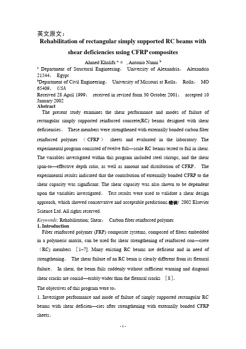
英文原文:Rehabilitation of rectangular simply supported RC beams with shear deficiencies using CFRP compositesAhmed Khalifa a,*, Antonio Nanni ba Department of Structural Engineering,University of Alexandria,Alexandria 21544,Egyptb Department of Civil Engineering,University of Missouri at Rolla,Rolla,MO 65409,USAReceived 28 April 1999;received in revised form 30 October 2001;accepted 10 January 2002AbstractThe present study examines the shear performance and modes of failure of rectangular simply supported reinforced concrete(RC) beams designed with shear deficiencies。
These members were strengthened with externally bonded carbon fiber reinforced polymer (CFRP)sheets and evaluated in the laboratory. The experimental program consisted of twelve full—scale RC beams tested to fail in shear. The variables investigated within this program included steel stirrups, and the shear span-to—effective depth ratio, as well as amount and distribution of CFRP。
![[中英]土木工程专业英语词汇](https://img.taocdn.com/s1/m/68d33d03e55c3b3567ec102de2bd960591c6d957.png)
土木工程专业英语词汇第一节一般术语1. 工程结构building and civil engineering structures房屋建筑和土木工程的建筑物、构筑物及其相关组成部分的总称。
2. 工程结构设计design of building and civil engineering structures在工程结构的可靠与经济、适用与美观之间,选择一种最佳的合理的平衡,使所建造的结构能满足各种预定功能要求。
3. 房屋建筑工程building engineering一般称建筑工程,为新建、改建或扩建房屋建筑物和附属构筑物所进行的勘察、规划、设计、施工、安装和维护等各项技术工作和完成的工程实体。
4. 土木工程civil engineering除房屋建筑外,为新建、改建或扩建各类工程的建筑物、构筑物和相关配套设施等所进行的勘察、规划、设计、施工、安装和维护等各项技术工作和完成的工程实体。
5. 公路工程highway engineering为新建或改建各级公路和相关配套设施等而进行的勘察、规划、设计、施工、安装和维护等各项技术工作和完成的工程实体。
6. 铁路工程railway engineering为新建或改建铁路和相关配套设施等所进行的勘察、规划、设计、施工、安装和维护等各项技术工作和完成的工程实体。
7. 港口与航道工程port ( harbour ) and waterway engineering为新建或改建港口与航道和相关配套设施等所进行的勘察、规划、设计、施工、安装和维护等各项技术工作和完成的工程实体。
8. 水利工程hydraulic engineering为修建治理水患、开发利用水资源的各项建筑物、构筑物和相关配设施等所进行的勘察、规划、设计、施工、安装和维护等各项技术工作和完成的工程实体。
9. 水利发电工程(水电工程)hydraulic and hydroelectric engineering以利用水能发电为主要任务的水利工程。

Earthquake Resistant Structural Systems -土木工程外文翻译3Building Engineering Ⅱ: Building Structures and SeismicResistance3.1Text3.1.1PassageEarthquake ResistantStructural Systems1Rigid Frame StructuresRigid frame structures typically comprise floor diaphragms supported on beams which link to continuous columns (Figure 3-1). The joints between beam and columns are usually considered to be “rigid”. The frames are expected to carry the gravity loads through the flexural action of the beams and the prop ping action of the columns. Negative moments are induced in the beam adjacent to the columns causing the mid-span positive moment to be significantly less than in a simply supported span. In structures in which gravity loads dictate the design, economies in member size that arise from this effect tend to be offset by the higher cost of the rigid joints.Figure 3-1 Rigidframe structureLateral loads, imposed within the plane of the frame, are resisted through the development of bending moments in the beams and columns. Framed buildings often employ moment resistant frames in two orthogonal directions, in which case the column elements are common to both frames.Rigid frame structures are well suited to accommodate high levels of inelastic deformation. When a capacity design approach is employed, it is usual to assign the end zones of the flexural beams to accept the post-elastic deformation expected, and to design the column members such that their dependable strength is in excess of the over-strength capacity of the beam hinges, thereby ensuring they remain within their elastic response range regardless of the intensity of ground shaking. Rigid frame structures are, however, often quite flexible. When they aredesigned to be fully ductile, special provisions are often needed to prevent the premature onset of damage to non-structural components.Rigid frame construction is ideally suited for reinforced concrete building because of the inherent rigidity of reinforced concrete joints. The rigid frame form is also used for steel framebuildings. But moment resistant connections in steel tend to be costly. The sizes of the columns and girders at any level of a rigid-frame are directly influenced by the magnitude of the external shear at that level, and they therefore increase toward the base. Consequently, the design of the floor framing can not be repetitive as it is in some braced frames. A further result is that sometimes it is not possible in the lowest storeys to accommodate the required depth of girder within the normal ceiling space.While rigid frames of a typical scale that serve alone to resist lateral loading have an economic height limit of about 25 storeys, smaller scale rigid frames in the form of a perimeter tube, or typically scaled rigid frames in combination with shear walls or braced bents, can be economic up to much greater heights.2Infilled Frame StructuresInfilled frames (Figure 3-2) are the most usual form of construction for tall buildings of up to 30 storeys in height. Column and girder framing of reinforced concrete, or sometimes steel, is infilled by panels of brickwork, or cast-in-place concrete.Figure 3-2 InfilledframeWhen an infilled frame is subjected to lateral loading, the infill behaves effectively as a strut along its compression diagonal to brace the frame. Because the infills serve also as external walls or internal partitions, the system is an economical way of stiffening and strengthening the structure.The complex interactive behavior of the infill in the frame, and the rather random quality of masonry, had made it difficult to predicate with accuracy the stiffness and strength of an infilled frame. For these reasons, the use of the infills for bracing buildings has mainly been supplementary to the rigid frame action of concrete frames.3Shear WallsA shear wall is a vertical structural element that resists lateral forces in the plane of the wall through shear and bending. The high in planstiffness and strength of concrete and masonry walls make them ideally suitable for bracing building as shear walls.A shear wall acts as a beam cantilevered out of the ground or foundation9 and, just as with a beam, part of its strength derives from its depth. Figure 3-3 shows two examples of a shear wall, one in a simple one-storey building and another in a multistorey building. In Figure 3-3a, the shear walls are oriented in one direction, so only lateral forces in this direction can be resisted. The roof serves as the horizontal diaphragm and must also be designed to resist the lateral loads and transfer them to the shear walls.a) End shear walls and interior shear wall b)Interior shear walls forbracing in two directionFigure 3-3 Shear wallFigure 3-3a also shows an important aspect of shear walls in particular and vertical elements in general. This is the aspect of symmetry that has a bearing on whether torsional effects will be produced. The shear walls in Figure 3-3a show the shear walls symmetrical in the plane of loading.Figure 3-3b illustrates a common use of shear walls at the interior of a multi-storey building. Because walls enclosing stairways, elevator shafts, and mechanical chases are mostly solid and run the entire height of the building, they are often used for shear walls. Although not as efficient from a strictly structural point of view, interior shear walls do leave the exterior of the building open for windows.Notice that in Figure 3-3b there are shear walls in both directions, which is a more realistic situation because both wind and earthquake forces need to be resisted in both directions. In this diagram, the two shear walls are symmetrical in one direction, but the single shear wall produces a nonsymmetric condition in the other since it is off center. Shear walls do not need to be symmetrical in a building, but symmetry is preferred to avoid torsional effects. If, in low-to medium-rise building, shear walls are combined with frames, it is reasonable to assume that the shear wall attract all the lateral loading so that the frame may be designed for only gravity loading. It is essentially important in shear wall structures to try to plan the wall layout so that the lateral load tensile stresses are suppressed by the gravity load stresses. This allows them to be designed to have only the minimum reinforcement.Since shear walls are generally both stiff and can be inherently robust, it is practical to design them to remain nominally elastic under design intensity loadings, particularly in regions of low or moderate seismicity. Under increased loadingintensities, post-elastic deformations will develop within the lower portion of the wall (generally considered to extend over a height of twice the wall length above the foundation support system).Good post-elastic response can be readilyachieved within this region of reinforced concrete or masonry shear walls through the provision of adequate confinement of the principal reinforcing steel and the prohibition oflap splices of reinforcing bars. Shear wall structures are generally quite stiff and, as such interstorey drift problems are rare and generally easily contained. The shear wall tends to act as a rigid body rotating about a plastic hinge which forms at the base of the wall. Overall structural deformation is thus a function of the wall rotation. Inter-storey drift problems which do occur are limited to the lower few floors.A major shortcoming with shear walls within buildings is that their size provides internal (or external) access barriers which may contravene the architectural requirements. This problem canbe alleviated by coupling adjacent more slender shear walls so a coupled shear wall structure is formed. The coupling beams then become shear links between the two walls and with careful detailing can provide a very effective, ductile control mechanism (Figure 3-4).Figure 3-4 Coupled shear wallstructure4Braced FramesA braced frame is a truss system of the concentric or eccentric type in which the lateral forces are resisted through axial stresses in the members. Just as with a truss, the braced frame depends on diagonal members to provide a load path for lateral forces from each building element to the foundation. Figure 3-5 shows a simple one-storey braced frame. At one end of the building two bays are braced and at the other end only one bay is braced. This building is only braced in one direction and the diagonal member may be either in tension or compression,depending on which way the force is applied.a)Single story braced buildingb) Multistory bracedbuilding Figure 3-5Braced frameFigure 3-5b shows two methods of bracing a multistorey building. A single diagonal compression member in one bay can be used to brace against lateral loads coming from either direction. Alternately, tension diagonals can be used to accomplish the same result, but they must be run both ways to account for the load coming from either direction.Braced framing can be placed on the exterior or interior of a building, and may be placed in one structural bay or several. Obviously, a braced frame can present design problems for windows and doorways, but it is a very efficientand rigid lateral force resisting system.Two major shortcomings of braced systems are that their inclined diagonal orientation oftenconflicts with conventional occupancy use patterns; and secondly they often require careful detailing to avoid large local torsional eccentricities being introduced at the connections with the diagonal brace being offset from the frame node.5Wall-frame StructuresWhen shear walls are combined with rigid frames (Figure 3-6), the walls, which tend to deflect in a flexural configuration, and the frames, which tend to deflect in a shear mode, are constrained to adopt a common shape by the horizontal rigidity of the girders and slabs. As a consequence, the walls and frames interact horizontally, especially at the top, to produce a stiffer and stronger structure. The interacting wall-frame combination is appropriate for buildings in the 40-to-60-storey range, well beyond of rigid frame or shear wall alone.Figure 3-6Wall-frame structureIn addition, less well-known feature of the wall- frame structure is that, in a carefully “tuned” structure, the shear in the frame can be made approximately uniform over the height, allowing the floor framing to be repetitive. Although the wall-frame structure is usually perceived as a concrete structural form, with shear walls and concrete frames, a steel counterpart using braced frames and steel rigid frames offers similar benefit of horizontal interaction. The braced frames behave with an overall flexural tendency to interact with the shear mode of the rigid frames.6Framed-Tube StructuresThe lateral resistance of framed-tube structures is provided by very stiff moment resisting frames that form a “tube” around the perimeter of the building. The frames consist of closely spaced column, 2~4m between centers, joined by deep spandrel girders (Figure 3-7). Although the tube carries all the lateral loading, the gravity load is shared between the tube and interior columns or walls. When lateral loading acts, the perimeter frames aligned in thedirection of loading act as the “web” of the massive tube cantilever, and those normal to the direction of the loading act as the “flanges”.Figure 3-7Frame-tube structureThe close spacing of the columns throughout the height of the structures is usually unacceptable at the entrance level. The columns are therefore merged, or terminated on a transfer beam, a few storeys above the base so that only a few, larger, more widely spaced columns continue to the base. The tube form was developed originally for buildings of rectangular plan; however, for other plan shapes, and has occasionally been used in circular and triangular configurations.The tube is suitable for both steel and reinforced construction and has been used for buildings ranging from 40 to more storeys. The highly repetitive pattern of the frames lends itself to prefabrication in steel, and to the use of rapidly gang forms in concrete, which make for rapid construction.The framed tube has been one of the most significant modern developments in high-rise structural form. It offers a relatively efficiently, easily constructed structure, appropriate for use up to the greatest of heights. Aesthetically, the tube’s externally evident form is regarded with mixed enthusiasm: some praise the logical clearly expressed structure while others criticize the girder-like façade as small-windowed and uninteresting repetitious.The tube structure’s structural efficiency, although high, still leaves scope for improvement because the “flange” frames tend to suffer from “shear lag”; this result in mid-face “flange” columns being less stresses than the corner columns and, therefore, not contributing as fully as they could to the flange action.7Tube-in-Tube or Hull-Core StructuresThis variation of the framed tube consists of an outer framed tube, the “hull” together with an internal elevator and service core (Figure 3-8). The hull and the inner core act jointly in resisting both gravity and lateral loading. In a steel structure the core may consist of braced frames, whereas in a concrete structure it wouldconsist of an assembly of shear walls.Figure 3-8Tube-in-tubeTo some extent, the outer framed tube and the inner core interact horizontally as the shear and flexural components of a wall-frame structure, with the benefit of increase lateral stiffness. However, the structural tube usually adopts a highly dominant role because of its much greater structural depth.8Braced-Tube StructuresAnother way of improving the efficiency of the framed tube, thereby increasing its potential for greater heights as well as allowing greater spacing between the columns, is to add diagonal bracing to the faces of the tube. This arrangement was first used in a steel structure in 1969, in Chicago’s John Hancock Building (Figure 3-9). Because the diagonal of a braced tube are connected to the columns at each intersection, they virtually eliminate the effects of shear lag in both the flange and web frames.As a result, the structure behaves under lateral loading more like a braced frame, with greatly diminished bending in the members of the frames. Consequently, the spacing of the columns can be larger and the depth of the spandrels less, thereby allowing larger size windows than in the conventional tube structure.Figure 3-9Braced-TubeStructuresIn the braced-tube structure the bracing contributes also to the improved performance of the tube in carrying gravity loading: differences between gravity load stresses in the columns are evened out by the braces transferring loading from the more highly to the less highly stressed columns.9Bundled-Tube StructuresThis structural form has been used for the Sears Tower in Chicago. The Sears Tower consists of four parallel rigid steel frames in each orthogonal direction, interconnected to form nine “bundled” tubes. As in the single-tube structure, the frames in the direction of lateral loading serves as “webs” of the vertical cantilever, with the normal frame acting as “flanges”.The introduction of internal webs greatly reduces the shear lag in the flanges; consequently their columns are more evenly stressed than in the single-tube structure, and their contribution to the lateral stiffness is great. This allows columns of the frames to be spaced further apart and to be less obtrusive. In the Sears Tower, advantage was taken of the bundled form to discontinue some of the tubes, and so reduce the plan of the building at stages up to the height.3.1.2New Words and Expressionsbraced frame支撑框架braced-tube桁架筒bundled-tube束筒couplingbeam 连梁coupledshear wall 联肢墙framedtube 框筒inter-storeydrift 层间位移propping[ 'prɔpiŋ ] n. 支撑rigid frame框架shear lag 剪力滞后spandrel [ 'spændrəl ] n.上下层窗间墙stairway [ 'stεəwei ] n.楼梯transfer beam 转换粱tube-in-tube / hull-core 筒中筒wall-frame structure 框架-剪力墙结构3.1.3Exercises1Please name the types of earthquake resistant structural systems.2How does a rigid frame structureresist the gravity load and lateralload? 3 Why are shear walls in both directions preferred?4 How are the loads shared between frame and tube in a framed-tube structure?3.2Reading Materials3.2.1Passage OneReinforced ConcreteStructuresConcrete and reinforced concrete are used as building materials in every country. In many, including the United States and Canada, reinforced concrete is a dominant structural material in engineered construction. The universal nature of reinforced concrete construction stems from thewide availability of reinforcing bars and the constituents of concrete, gravel, sand, and cement, the relatively simple skills required in concrete construction, and the economy of reinforced concrete compared to other forms of construction. Concrete and reinforced concrete are used in bridges, buildings of all sorts, underground structures, water tanks, television towers, offshore oil exploration and production structures, dams, and even in ships.1Mechanics of Reinforced Concrete Concrete is strong in compression but weak in tension. As a result, cracks develop whenever loads, or restrained shrinkage or temperature changes, give rise to tensile stresses in excess of the tensile strength of the concrete. In the plain concrete beam, the moments due to applied loads are resisted by an internal tension-compression couple involving tension in the concrete. Such a beam fails very suddenly and completely when the first crack forms. In a reinforced concrete beam, steel bars are embedded in the concrete in such a way that the tension forces needed for moment equilibrium after the concrete cracks can be developed in the bars.The construction of a reinforced concrete member involves building a form or mold in the shape of the member being built. The form must be strong enough to support the weight and hydrostatic pressure of the wet concrete, and any forces applied to it by workers, concrete buggies, wind, and so on. The reinforcement is placed in this form and held in place during the concreting operation. After the concrete has hardened, the forms are removed.2Factors Affecting Choice of Concrete for aStructureThe choice of whether a structure should be built of concrete, steel, masonry, or timber depends on the availability of materials and on a number of value decisions.(1)EconomyFrequently, the foremost consideration is the overall cost of the structure. This is, of course, a function of the costs of the materials and the labor necessary to erect them. Frequently, however, the overall cost is affected as much or more by the overall construction time since the contractor and owner must allocate money to carry out the construction and will not receive a return on this investment until the building isready for occupancy. As a result, financial savings due to rapid construction may more than offset increased material costs. Any measures the designer can take to standardize the design and forming will generally pay off in reduced overall costs.In many cases the long-term economy of the structure may be more important than the first cost. As a result, maintenance and durability are important considerations.(2)Suitability of Material for Architectural andStructural FunctionA reinforced concrete system frequently allows the designer to combine the architectural and structural functions. Concrete has the advantage that it is placed in a plastic condition and is given the desired shape and texture by means of the forms and the finishing techniques. This allows such elements as flat plates or other types of slabs to serve as load-bearing elements while providing the finished floor and ceiling surfaces. Similarly, reinforced concrete wails can provide architecturally attractive surfaces in addition to having the ability to resist gravity, wind, or seismic loads. Finally, the choice of size or shape is governed by the designer and not bythe availability of standard manufactured members.(3)Fire ResistanceThe structure in a building must withstand the effects of a fire and remain standing while the building is evacuated and the fire is extinguished.A concrete building inherently has a 1- to 3-hour fire rating without special fireproofing or other details. Structural steel or timber buildings must befireproofed to attain similar fire ratings.(4)RigidityThe occupants of a building may be disturbed if their building oscillates in the wind or the floors vibrate as people walk by. Due to the greater stiffness and mass of a concrete structure, vibrations are seldom a problem.(5)Low MaintenanceConcrete members inherently require less maintenance than do structural steel or timber members. This is particularly true if dense, air-entrained concrete has been used for surfaces exposed to the atmosphere, and if care has been taken in the design to provide adequate drainage off and away from the structure.(6)Availability of MaterialsSand, gravel, cement, and concrete mixing facilities are very widely available, and reinforcing steel can be transported to most job sites more easily than can structural steel. As a result, reinforced concrete is frequently used in remote areas.On the other hand, there are a number of factors that may cause one to select a material other than reinforced concrete. These include: (1)Low Tensile StrengthAs stated earlier, the tensile strength of concrete is much lower than its compressive strength (about 1/10), and hence concrete is subject to cracking. In structural uses this is overcome by using reinforcement to carry tensile forces and limit crack widths to within acceptable values. Unless care is taken in design and construction, however, these cracks may be unsightly or may allow penetration of water.(2)Forms and ShoringThe construction of a cast-in-place structure involves three steps not encountered in the construction of steel or timber structures. These are the construction of the forms, the removal of these forms, and propping or shoring the new concrete to support its weight until its strength is adequate. Each of these steps involves labor and/or materials which are not necessary with other forms of construction.(3)Relatively Low Strength per Unit of Weightor VolumeThe compressive strength of concrete is roughly 5% to 10% that of steel, while its unit density is roughly 30% that of steel. As a result, a concrete structure requires a larger volume and a greater weight of material than does acomparable steel structure. As a result, long-span structures are often built from steel.(4)Time-dependent Volume ChangesBoth concrete and steel undergo approximately the same amount of thermal expansion and contraction. Because there is less mass of Steel to be heated or cooled, and because steel is a better conductor than concrete, a steel structure is generally affected by temperature changes to a greater extent than is a concrete structure. On the other hand, concrete undergoes drying shrinkage, which, if restrained, may cause deflections or cracking. Furthermore, deflections will tend to increase with time, possibly doubling, due to creep of the concrete under sustained loads.3Building CodesThe first set of building regulations for reinforced concrete were drafted under the leadership of Professor Morsch of the University of Stuttgart and were issued in Prussia in 1904. Design regulations were issued in Britain, France, Austria, and Switzerland between 1907 and 1909.The American Railway Engineering Association appointed a Committee on Masonry in 1890. In 1903 this committee presented specifications for Portland cement concrete. Between 1908 and 1910 a series of committee reports led to the Standard Building Regulations for the Use of Reinforced Concrete published in 1910 by the National Association of Cement Users which subsequently became the American Concrete Institute.A Joint Committee on Concrete and Reinforced Concrete was established in 1904 by the American Society of Civil Engineers, American Society for Testing and Materials, the American Railway Engineering Association, and the Association of American Portland Cement Manufactures. This group was later joined by the American Concrete Institute. Between 1904 and 1910 the Joint Committee carried out research. A preliminary report issued in 1913 lists the more important papers and books on reinforced concrete published between 1898 and 1911. The final report of this committee was published in 1916. The history of reinforced concrete building codes in the United States wasreviewed in 1954 by Kerekes and Reid.The design and construction of buildings is regulated by municipal bylaws called building codes. These exist to protect the public health and safety. Each city and town is free to write or adopt its own building code, and in that city or town, only that particular code has legal status. Because of the complexity of building code writing, cities in the United States generally base their building codes on one of three model codes: the Uniform Building Code, the Standard Building Code, or the Basic Building Code. These codes cover such things as use and occupancy requirements, fire requirements, heating and ventilating requirements, and structural design.The definitive design specification for reinforced concrete buildings in North America is the Building Code Requirements for Reinforced Concrete (ACI-318-95), which is explained in a Commentary.This code, generally referred to as the ACI Code, has been incorporated in most building codes in the United States and serves as the basis for comparable codes in Canada, New Zealand,Australia, and parts of Latin America. The ACI Code has legal status only if adopted in a local building code.Each nation or group of nations in Europe has its own building code for reinforced concrete. The CEB-FIP Model Code for Concrete Structures is intended to serve as the basis for future attempts to unify European codes. This code and the ACI Code are similar in many ways.3.2.2Passage TwoEarthquake Induced Vibration ofStructures1Seismicity and Ground MotionsThe most common cause of earthquakes is thought to be the violent slipping of rock masses along major geological fault lines in the Earth’s crust, or lithosphere. These fault lines divide the global crust into about 12 major tectonic plates, which are rigid, relatively cool slabs about 100km thick. Tectonic plates float on the molten mantle of the Earth and move relative to one another at the rate of 10 to 100mm/year.The basic mechanism causing earthquakes inthe plate boundary regions appears to be that the continuing deformation of the crustal structure eventually leads to stresses which exceed the material strength. A rupture will then initiate at some critical point along the fault line and willpropagate rapidly through the highly stressed material at the plate boundary. In some cases, the plate margins are moving away from one another. In those cases, molten rock appears from deep in the Earth to fill the gap, often manifesting itself as volcanoes. If the plates are pushing together, one plate tends to dive under the other and, depending on the density of the material, it may resurface in the form of mountains and valleys. In both these scenarios, there may be volcanoes and earthquakes at the plate boundaries, both being caused by the same mechanism of movement in the Earth's crust. Another possibility is that the plate boundaries will slide sideways past each other, essentially retaining the local surface area of the plate. It is believed that about three quarters of the world's earthquakes are accounted for by this rubbing-striking-slipping mechanism, with ruptures occurring on faults on boundaries between tectonic plates. Earthquake occurrence maps tend to outline the plate boundaries. Such earthquakes are referred to as interplate earthquakes.Earthquakes also occur at locations away。
Experimental research on seismic behavior of abnormal jointin reinforced concrete frameAbstract :Based on nine plane abnormal joint s , one space abnormal joint experiment and a p seudo dynamic test of a powerplant model , the work mechanism and the hysteretic characteristic of abnormal joint are put to analysis in this paper. A conception of minor core determined by the small beam and small column , and a conclusion that the shear capacity of ab2normal joint depends on minor core are put forward in this paper. This paper also analyzes the effect s of axial compres2 sion , horizontal stirrup s and section variation of beam and column on the shear behavior of abnormal joint . Finally , the formula of shear capacity for abnormal joint in reinforced concrete f rame is provided.Key words : abnormal j oint ; minor core ; seismic behavior ; shear ca paci t yCLC number :TU375. 4 ; TU317. 1 Document code :A Article ID :100627930 (2006) 022*******1 Int roductionFor reinforced concrete f rame st ructure , t he joint is a key component . It is subjected to axialcomp ression , bending moment and shear force. The key is whet her the joint has enough shear capaci2ty. The Chinese Code f or S eismic Desi gn of B ui l di ngs ( GB5001122001) adopt s the following formulato calculate t he shear capacity of the reinforced concrete f rame joint .V j = 1. 1ηj f t b j h j + 0. 05ηj Nb jb c+ f yv A svjh b0 - a′ss(1)Where V j = design value of t he seismic shear capacity of the joint core section ;ηj = influential coefficient of t he orthogonal beam to the column ;f t = design value of concrete tensile st rength ;b j = effective widt h of the joint core section ;h j = dept h of the joint core section , Which can be adopted as t he depth of the column section int he verification direction ;N = design value of axial compression at t he bot tom of upper column wit h considering the combi2 nation of the eart hquake action , When N > 015 f c b c h c , let N = 0. 5 f c b c h c ;b c = widt h of t he column section ;f yv = design value of t he stirrup tensile st rengt h ;A svj = total stirrup area in a set making up one layer ;h b0 = effective dept h of t he beam.If t he dept h of two beams at the side of t he joint is unequal , h b0 = t he average depth of two beams.a′s = distance f rom the cent roid of the compression beam steel bar to the ext reme concrete fiber . s = distance of t he stirrup .Eq. 1 is based on t he formula in t he previous seismiccode[1 ] and some modifications made eavlicr and it is suit2able to the normal joint of reinforced concrete f rame , butnot to t he abnormal one which has large different in t hesection of t he upper column and lower one (3 600 mm and1 200 mm) , lef t beam and right beam (1 800 mm and 1200 mm) . The shear capacity of abnormal joint s calculat2ed by Eq. 1 may cause some unsafe result s. A type of ab2normal joint which of ten exist s in t he power plant st ruc2t ure is discussed ( see Fig. 1) , and it s behavior was st ud2ied based on t he experiment in t his paper2 Experimental workAccording to the above problem , and t he experiment of plane abnormal joint s and space abnormal joint , a p seudo dynamic test of space model of power plant st ruct ure was carried out . The aim of t hisst udy is to set up a shear force formula and to discuss seismic behavior s of t he joint s.According to the characteristic of t he power plant st ruct ure , nine abnormal joint s and one space abnormal joint were designed in t he experiment . The scale of the model s is one2fif t h. Tab. 1 and Tab.2 show t he dimensions and reinforcement detail s of t he specimens.Fig. 2 shows the typical const ruction drawing of t he specimen. Fig. 3 shows the loading set up . These specimens are subjected to low2cyclic loading , the loading process of which is cont rolled by force and displacement , t he preceding yield loading by force and subsequent yield by t he displacement .The shear deformation of the joint core , t he st rain of the longit udinal steel and t he stirrup are main measuring items.3 Analysis of test result s3. 1 Main resultsTab. 3 shows t he main result s of t he experiment .3. 2 Failure process of specimenBased on t he experiment , t he process of t he specimens’failure includes four stages , namely , t he initial cracking , t he t horough cracking , the ultimate stage and t he failure stage.(1) Initial cracking stageWhen t he first diagonal crack appears along t he diagonal direction in t he core af ter loading , it s widt h is about 0. 1mm , which is named initial cracking stage of joint core. Before t he initial cracking stage , t he joint remains elastic performance , and the variety of stiff ness is not very obvious on t hep2Δcurve. At t his stage concrete bear s most of the core shear force while stirrup bears few. At t he timewhen t he initial crack occur s , t he st ress of t he stirrup at t he crack increase sharply and t he st rain is a2bout 200 ×10 - 6 —300 ×10 - 6 . The shear deformation of t he core at t his stage is very small (less than 1×10 - 3 radian ,generally between 0. 4 ×10 - 3 and 0. 8 ×10 - 3 radian) .(2) Thorough cracking stageWit h the load increasing following t he initial cracking stage , the second and t hird crossing diago2 nal cracks will appear at t he core. The core is cut into some small rhombus pieces which will become at least one main inclined crack across t he core diagonal . The widt h of cracks enlarges obviously , andt he wider ones are generally about 0. 5mm , which is named core t horough cracking stage. The st ress of stirrup increases obviously , and the stirrup in t he middle of t he core is near to yielding or has yiel2 ded. The joint core shows nonlinear property on t he p2Δcurve , and it enter s elastic2plastic stage. Theload at t horough cracking stage is about 80 % —90 % load.(3) Ultimate stageAt t his stage , t he widt h of t he cracks is about 1mm or more and some new cracks continue to oc2 cur . The shear deformation at t he core is much larger and concrete begins to collap se. Af ter several cyclic loading , the force reaches the maximum value , which is called ultimate stage. The load increase is due to t he enhancing of the concrete aggregate mechanical f riction between cracks. At t he same timet he st ress of stirrup increases gradually. On t he one hand stirrup resist s t he horizontal shear , and on t he ot her hand the confinement effect to t he expanding compression concrete st rengthens continuous2ly , which can also improve t he shear capacity of diagonal compression bar mechanism.(4) Failure stageAs the load circulated , concrete in t he core began to collap se , and t he deformation increased sharply , while the capacity began to drop . It was found t hat t he slip of reinforcement in t he beam wasvery serious in t he experiment . Wit h t he load and it s circulation time increasing , t he zoon wit houtbond gradually permeated towards t he internal core , enhancing t he burden of t he diagonal compressionbar mechanism and accelerates the compression failure of concrete. Fig. 4 shows t he p hotos of typical damaged joint s.A p seudo dynamic test of space model ofpower plant st ruct ure was carried out to researcht he working behavior of t he abnormal joint s in re2al st ructure and the seismic behavior of st ructure.Fig. 5 shows the p hoto of model .The test includes two step s. The fir st is thep seudo dynamic test . At t his step , El2Cent rowave is inp ut and the peak acceleration variesf rom 50 gal to 1 200 gal . The seismic response is measured. The second is t he p seudo static test . Theloading can’t stop until t he model fail s.Fig. 7 Minor coreThe experiment shows t hat t he dist ribution and development of t hecrack is influenced by t he rest rictive effect of the ort hogonal beam , andt he crack of joint core mainly dist ributes under t he orthogonal beam( see Fig. 6) , which is different f rom t he result of t he plane joint test ,but similar to J 4210.3. 3 Analysis of test results3. 3. 1 Mechanical analysisIn t he experiment , t he location of the initial crack of t he exteriorjoint and the crushed position of concrete both appear in the middle oft he joint core , and t he position is near t he centerline of t he upper col2umn. The initial crack and crushed position of t he concrete of the interior joint both appear in t he mi2 nor core ( see Fig. 4 ,Fig. 7) . For interior abnormal joint t he crack doesn’t appear or develop in t he ma2j or core out side of the mi nor core until t horough cracking takes place , while t he crack seldom appearsin t he shadow region ( see Fig. 7) as the joint fail s. Therefore , for abnormal joint , t he shear capacity oft he joint core depends on t he properties of t he mi nor core , namely , on t he st rengt h grades of concrete ,t he size and the reinforcement of t he mi nor core , get t he effect of t he maj or core dimension can’t be neglected.Mechanical effect s are t he same will that of t he normal joint , when t he forces t ransfer to t he mi2 nor core t hrough column and beam and reinforcement bar . Therefore , t he working mechanisms of nor2mal joint , including t russ mechanism , diagonal compression bar mechanism and rest rictive mechanismof stirrup , are also suitable for mi nor core of t he abnormal joint , but their working characteristic is not symmet rical when the load rever ses. Fig. 8 illust rates t he working mechanism of t he abnormal joint .When t he load t ransfer to mi nor core , t he diagonal compression bar area of mi nor core is biggert han normal joint core2composed by small column and small beam of abnormal joint , which is due to t he compressive st ress diff usion of concrete compressive region of the beam and column , while at t hesame time t he compression carried by the diagonal compression bar becomes large. Because t he main part of bond force of column and beam is added to t he diagonal comp ression bar but cont rasting wit h t he increased area of diagonal compression bar , t he increased action is small . The region in the maj orcore but out of the mi nor core has less st ress dist ribution and fewer cracks. The region can confine t heexpansion of t he concrete of t he mi nor core diagonal compression bar concrete , which enhances t he concrete compressive st rengt h of mi nor core diagonal compression bar .Making t he mi nor core as st udy element , the area increment of concrete diagonal compression barin mi nor core is related to t he st ress diff usion of t he beam and column compressive region. The magni2t ude of diff usion area is related to height difference of t he beam sections and column sections. Name2ly , it is related to t he size of mi nor core section and maj or core section. Thus , the increased shearst rengt h magnit ude caused by mi nor core rest rictive effect on maj or core can be measured quantitative2ly by t he ratio of maj or core area to mi nor core area. And it al so can be expressed that t he rest rictive effect is quantitatively related to t he ratio. Obviously , t he bigger t he ratio is and t he st ronger t he con2finement is , t he st ronger t he bearing capacity is.The region in the maj or core but under the mi nor core still need stirrup bar because of t he hori2 zontal force t ransferred by bigger beam bar . But force is small .3. 3. 2 load2displacement curves analysisFig. 9 shows t he typical load2displacement curves at t he beam end of t he exterior and interiorjoint . The figure showing t hat t he rigidity of t he specimens almo st doesn’t degenerate when t he initialcrack appear s in t he core , and a turning point can be found at t he curve but it isn’t very obvious. Wit ht he crack developing , an obvious t urning point can be found at t he curve , and at t his time , t he speci2men yields. Then t he load can increase f urt her , but it can’t increase too much f rom yielding load to ultimate load. When t he concrete at t he core collap ses and the plastic hinge occured at t he beamend ,t he load begins to decrease rat her t han increase.The ductility coefficient of two kinds of joint s is basically more than 3 (except for J 3 - 9) . But it should be noted t hat the design of specimens is based on the principle of joint core failure. The ratio of reinforcement of beam and column tends to be lower t han practical project s. If t he ratio is larger , t he failure of joint is probably prior to t hat of beam and column , so t he hysteretic curve reflect s t he ductil ity property of joint core.Joint experiment should be a subst ruct ure test (or a test of composite body of beams and col2 umns) . So t he load2displacement curves at t he beam end should be a general reflection of t he joint be2havior work as a subst ruct ure. Providing t hat the joint core fails af ter t he yield of beam and column (especially for beam) , t he load2displacement curves at t he beam end is plump , so the principle of “st rong col umn and weak beam , st ron ger j oi nt" should be ensured which conforms to t he seismic re2sistant principle.The experiment shows t hat t he stiff ness of joint core is large. Before the joint reaches ultimatestage , t he stiff ness of joint core decreases a little and the irrecoverable residual deformation is very small under alternate loading. When joint core enter s failure stage , t he shear deformation increases sharply , and t he stiff ness of joint core decreases obviously , and t he hysteretic curve appears shrink2 age , which is because of t he cohesive slip of beam reinforcement .3. 4 Influential Factors of Abnormal Joint Shear CapacityThe fir st factor is axial compression. Axial compression can enlarge t he compression area of col2 umn , and increase t he concrete compression area of joint core[124 ] . At t he same time , more shearst ransferred f rom beam steel to t he edge of joint core concrete will add to t he diagonal compression bar ,which decreases t he edge shear t hat leads to the crack of joint core concrete. So t he existence of axial comp ression cont ributes to imp roving t he capacity of initial cracks at joint core.The effect of axial compression on t horough cracking load and ultimate load isn’t very obvious[1 ] . The reason is t hat cont rasting wit h no axial compression , the accumulated damage effect of joint coreunder rever sed loading wit h axial compression is larger . Alt hough axial compression can improve t heshear st rengt h of concrete , it increases accumulated damage effect which leads to a decrease of the ad2vantage of axial compression. Therefore t he effect of axial compression on t horough cracking loadandultimate load is not very obvious.Hence , considering the lack of test data of abnormal joint , t he shear capacity formula of abnormal joint adopt 0. 05 nf c b j h j to calculate the effect of axial compression , which is based on the result s of t his experiment and referenced to t he experimental st udy and statistical analysis of Meinheit and J irsa ,et [5 ] .The second factor is horizontal stirrup . Horizontal stirrup has no effect on t he initial crackingshear of abnormal joint , while greatly improves t he t horough cracking shear . Af ter crack appeared , t he stirrup begins to resist t he shear and confines t he expansion of concrete[ 6 ] . This experiment showst hat t he st ress of stirrup s in each layer is not equal . When the joint fail s , t he stirrup s don’t yield simultaneous. Fig. 10 shows t he change of st ress dist ribution of stirrup s along core height wit h t he loadincreasing. Through analyzing test result s , it can be known t hat 80 percent of the height at the joint core can yield.The last factor is the change of sec2tion size of t he beam and column. Thesection change decreases t he initial crack2ing load about 30 p resent of abnormaljoint and makes t he initial crack appear att he position of joint mi nor core. The rea2son for t his p henomenon is t hat small up2per column section makes t he confinementof mi nor core concrete decrease and t heedge shear increase. But t he section change has lit tle effect on thorough cracking load. Af ter t horoughcracking , the joint enter s ultimate state while the external load can’t increase too much , which is dif2 ferent f rom t he behavior of abnormal joint t hat can carry much shear af ter thorough cracking.3. 5 Shear force formula of abnormal jointAs a part of f rame , t he design of joint shall meet t he requirement s of the f rame st ruct ure design , namely , t he joint design should not damage t he basic performance of t he st ruct ure.According to the principle of st ronger j oi nt , it is necessary for joint to have some safety reserva2 tion. The raised cost for conservational estimation of t he joint bearing capacity is small . But t he con2 servational estimation is very important to t he safety of the f rame st ruct ure. At t horough cracking stage , t he widt h of most cracks is more t han 0. 2 mm , which is bigger than t he suggested limit value in t he concrete design code. Big cracks will influence t he durability of st ruct ure. Hence , the bearing capacity at t horough cracking stage is applied to calculating t he bearing capacity of joint . According to t he analysis of t he working mechanisms of abnormal joint , it could be concludedt hat t he bearing capacity of joint core mainly depends on mi nor core when t he force t ransferred f rommaj or core to mi nor core. All kinds of working mechanisms are suitable to mi nor core element . Thus , a formula for calculating t he shear capacity of abnormal joint can be obtained based on Eq. 1. According to the above analysis of influential factor s of shear capacity of abnormal joint , and ref2 erence to Eq. 1 , a formula for calculating t he shear capacity of reinforced concrete f rame abnormal jointis suggested as followsV j = 0. 1ηjξ1 f c b j h j + 0. 1ηj nξ2 f c b j h j +ξ3 f yv A svj h0 - a′s s(2)Where h0 = effective dept h of small beam section in abnormal joint ;ξ1 = influential coefficient consider2ing mi nor core on working as cont rol element for calculating ;ξ2 = influential coefficient considering effect of axial compression ratio , it s value is 0. 5 , andξ3 = influential coefficient considering t hestir2rup doesn’t yield simultaneous , it s value is 0. 8 , n = N/ f c b c h j .From Fig. 8 , the shear capacity of abnormal joint depends on mi nor core , while maj or core has re2st rictive effect on mi nor core. The effect is related to t he ratio of maj or core area to mi nor core area , so assumingξ1 =αA d A x (3)Where A d = area of abnormal joint maj or core , choosing it as t he value of t he dept h of big beam multiplying t he height of lower column ; A x = area of abnormal joint mi nor core , choosing it as t he value oft he depth of small beam multiplying the height of upper column ; andα= parameter to be defined , it s value is 0. 8 derived f rom t he result s of t he experiment ( see Tab. 4)Then Eq. 2 can be replaced byV j = 0. 1ηjαA d A x f c b j h j + 0. 05ηj n f c b j h j + 0. 8 f yv h0 - a′s s(4)4 ConclusionsThe following conclusions can be drawn f rom t his study.(1) The seismic behavior of abnormal joint in reinforced concrete f rame st ruct ure is poor . Af tert horough cracking , t he joint enter s ultimate state while the external load can’t increase too much , andt he safety reservation of joint isn’t sufficient .(2) The characteristic of bearing load of minor core is similar to that of normal joint , but t he area bearing load is different . The shear capacity depend on t he size , t he st rengt h of concrete and the rein2forcement of mi nor core in abnormal joint . The maj or core has rest rictive effect on mi nor core. (3) Joint experiment should be a subst ruct ure test or a test of composite body of beams and col2 umns. Therefore t he load2displacement curves of t he beam end should be a general reflection of t he joint behavior working as a subst ruct ure. Studies of t he hysteretic curve of subst ruct ure should be based on t he whole st ructure. It is critical to guarantee t he stiff ness and st rengt h of joint core in prac2tice.(4) The formula of shear capacity for abnormal joint in reinforced concrete f rame is provided.References[1 ] TAN GJ iu2ru . The seismic behavior of steel reinforced concrete f rame [M] . Nanjing :Dongnan University Press ,1989 :1572163.[2 ] The research group of reinforcement concrete f rame joint . Shear capacity research of reinforced concrete f rame jointon reversed2cyclic loading[J ] . Journal of Building St ructures , 1983 , (6) :9215.[3 ] PAULA Y T ,PARK R. Joint s reinforced concrete f rames designed for earthquake resistance[ R] . New Zealand :De2partment of civil Engineering , University of Canterbury , Christchurch , 1984.[4 ] FU Jian2ping. Seismic behavior research of reinforced concrete f rame joint with the consideration of axialforce[J ] .Journal of Chongqing Univ , 2000 , (5) :23227.[5 ] MEINHEIT D F ,J IRSA J O. Shear st rength of R/ C beam2column connections [J ] . ACI St ructural Journal , 1993 ,(3) :61271.[6 ] KITA YAMA K, OTANI S ,AO YAMA H. Development of design criteria for RC interior beam2column joints ,de2sign of beam2column joint s for seismic resistance[ R] . SP123 ,ACI ,Det roit , 1991 :61272.[7 ] GB5001122001 ,Code for seismic design of buildings [ S] . Beijing : China Architectural and BuildingPress ,2001.钢筋混凝土框架异型节点抗震性能试验研究摘要:基于8个钢筋混凝土框架异型节点的试验研究,分析了异型框架节点的受力与常规框架节点的异同。

土木工程类英文专业词汇土木工程是一个涉及土地开发、设计、建造和维护的复杂领域。
在这个领域中,有许多具有专业性、特定含义和用途的英文术语。
掌握这些专业词汇对于在这个领域工作或学习的人来说非常必要。
本文将介绍土木工程常用的英语专业词汇。
1.Civil engineering –土木工程学Civil engineering is a discipline that deals with the design, construction, and maintenance of the built environment, including buildings, roads, bridges, and other infrastructure.2.Architecture –建筑学Architecture is the art and science of designing and building structures, such as buildings and bridges.3.Planning –规划Planning is the process of making a detailed plan or layout for a project, including determining what resources will be needed to complete the project.4.Surveying –测量Surveying is the process of measuring and mapping the surface of the Earth, including land, water bodies, and buildings.5.Structural engineering –结构工程Structural engineering is a sub-discipline of civil engineering that deals with the design and analysis of structures, such as buildings, bridges, and other infrastructure.6.Geotechnical engineering –岩土工程Geotechnical engineering is a sub-discipline of civil engineering that deals with the study of soil and rock mechanics, and the design and construction of structures that are built on or in the ground.7.Transportation engineering –交通运输工程Transportation engineering is a sub-discipline of civil engineering that dealswith the design and construction of transportation infrastructure, such as roads, highways, and airports.8.Hydrology –水文学Hydrology is the study of water and its movement on the surface of the Earth, including precipitation, streams, rivers, and groundwater.9.Water resources engineering –水资源工程Water resources engineering is a sub-discipline of civil engineering that deals with the study of water resources and the design and construction of structures that manage and distribute water, including dams, reservoirs, and water treatment plants.10.Environmental engineering –环境工程Environmental engineering is a sub-discipline of civil engineering that deals with the study of environmental engineering principles and the design and construction of structures that protect the environment, such as water treatment plants and wastewater treatment plants.11.Construction –建造Construction refers to the process of building structures from design plans and specifications.12.Industrial engineering –工业工程Industrial engineering is a discipline that deals with the optimization of complex processes, systems, and organizations, with the goal of improving efficiency, productivity, and safety.13.Quantity surveying –工程测量Quantity surveying is the process of determining the quantity, cost, and value of materials needed to complete a construction project.14.Building –建筑物Building refers to a structure that is built for a specific purpose, such as a house, office building, or factory.15.Foundation –基础Foundation refers to the part of a structure that is in direct contact with the ground and supports the weight of the structure.16.Reinforcement –钢筋加固Reinforcement refers to the process of adding materials, such as steel bars, to strengthen a structure.17.Retaining wall –挡土墙A retaining wall is a structure that is built to support soil and prevent it from sliding down a slope.18.Roadway –道路A roadway is a paved surface that is designed for vehicles and pedestrians to travel on.19.Bridge –桥梁A bridge is a structure that is built to span a physical obstacle, such as a river or gorge, and provide a safe means of transportation.20.Culvert –排水管A culvert is a structure that is built to allow water to pass under a roadway or other structure.21.Dam –水坝A dam is a structure that is built to control the flow of water and to provide water for human consumption, irrigation, and hydroelectric power.22.Pile –桩A pile is a foundation support structure that is driven into the ground to supporta structure.23.Slab –地板A slab is a flat, horizontal surface that is used as a flooring material or to supporta structure.24.Tunnel –隧道A tunnel is an underground structure that is built for transportation, utilities, or other purposes.25.Asphalt –沥青Asphalt is a sticky, black, and highly viscous liquid that is used as a binder for paving materials.以上就是土木工程类英文专业词汇的介绍,这些专业词汇对于在土木工程领域中工作或学习的人来说都是非常重要的。

7 Rigid-Frame StructuresA rigid-frame high-rise structure typically comprises parallel or orthogonally arranged bents consisting of columns and girders with moment resistant joints. Resistance to horizontal loading is provided by the bending resistance of the columns, girders, and joints. The continuity of the frame also contributes to resisting gravity loading, by reducing the moments in the girders.The advantages of a rigid frame are the simplicity and convenience of its rectangular form.Its unobstructed arrangement, clear of bracing members and structural walls, allows freedom internally for the layout and externally for the fenestration. Rigid frames are considered economical for buildings of up to' about25 stories, above which their drift resistance is costly to control. If, however,a rigid frame is combined with shear walls or cores, the resulting structure is very much stiffer so that its height potential may extend up to 50 stories or more. A flat plate structure is very similar to a rigid frame, but with slabs replacing the girders As with a rigid frame, horizontal and vertical loadings are resisted in a flat plate structure by the flexural continuity between the vertical and horizontal components.As highly redundant structures, rigid frames are designed initially on the basis of approximate analyses, after which more rigorous analyses and checks can be made. The procedure may typically include the following stages:1. Estimation of gravity load forces in girders and columns by approximate method.2. Preliminary estimate of member sizes based on gravity load forces witharbitrary increase in sizes to allow for horizontal loading.3. Approximate allocation of horizontal loading to bents and preliminary analysisof member forces in bents.4. Check on drift and adjustment of member sizes if necessary.5. Check on strength of members for worst combination of gravity and horizontalloading, and adjustment of member sizes if necessary.6. Computer analysis of total structure for more accurate check on memberstrengths and drift, with further adjustment of sizes where required. This stage may include the second-order P-Delta effects of gravity loading on the member forces and drift..7. Detailed design of members and connections.This chapter considers methods of analysis for the deflections and forces for both gravity and horizontal loading. The methods are included in roughly the order of the design procedure, with approximate methods initially and computer techniques later. Stability analyses of rigid frames are discussed in Chapter 16.7.1 RIGID FRAME BEHAVIORThe horizontal stiffness of a rigid frame is governed mainly by the bending resistance of the girders, the columns, and their connections, and, in a tall frame, by the axial rigidity of the columns. The accumulated horizontal shear above any story of a rigid frame is resisted by shear in the columns of that story (Fig. 7.1). The shear causes the story-height columns to bend in double curvature with points of contraflexure at approximately mid-story-height levels. The moments applied to a joint from the columns above and below are resisted by the attached girders, which also bend in double curvature, with points of contraflexure at approximately mid-span. These deformations of the columns and girders allow racking of the frame and horizontal deflection in each story. The overall deflected shape of a rigid frame structure due to racking has a shear configuration with concavity upwind, a maximum inclination near the base, and a minimum inclination at the top, as shown in Fig.7.1.The overall moment of the external horizontal load is resisted in each story level by the couple resulting from the axial tensile and compressive forces in the columns on opposite sides of the structure (Fig. 7.2). The extension and shortening of the columns cause overall bending and associated horizontal displacements of the structure. Because of the cumulative rotation up the height, the story drift dueto overall bending increases with height, while that due to racking tends to decrease. Consequently the contribution to story drift from overall bending may, in. the uppermost stories, exceed that from racking. The contribution of overall bending to the total drift, however, will usually not exceed 10% of that of racking, except in very tall, slender,, rigid frames. Therefore the overall deflected shape of a high-rise rigid frame usually has a shear configuration.The response of a rigid frame to gravity loading differs from a simply connected frame in the continuous behavior of the girders. Negative moments are induced adjacent to the columns, and positive moments of usually lesser magnitude occur in the mid-span regions. The continuity also causes the maximum girder moments to be sensitive to the pattern of live loading. This must be considered when estimating the worst moment conditions. For example, the gravity load maximum hogging moment adjacent to an edge column occurs when live load acts only on the edge span andalternate other spans, as for A in Fig. 7.3a. The maximum hogging moments adjacent to an interior column are caused, however, when live load acts only on the spans adjacent to the column, as for B in Fig. 7.3b. The maximum mid-span sagging moment occurs when live load acts on the span under consideration, and alternate other spans, as for spans AB and CD in Fig. 7.3a.The dependence of a rigid frame on the moment capacity of the columns for resisting horizontal loading usually causes the columns of a rigid frame to be larger than those of the corresponding fully braced simply connected frame. On the other hand, while girders in braced frames are designed for their mid-span sagging moment, girders in rigid frames are designed for the end-of-span resultant hogging moments, which may be of lesser value. Consequently, girders in a rigid frame may be smaller than in the corresponding braced frame. Such reductions in size allow economy through the lower cost of the girders and possible reductions in story heights. These benefits may be offset, however, by the higher cost of the more complex rigid connections.7.2 APPROXIMATE DETERMINATION OF MEMBER FORCES CAUSED BY GRAVITY LOADSIMGA rigid frame is a highly redundant structure; consequently, an accurate analysis can be made only after the member sizes are assigned. Initially, therefore, member sizes are decided on the basis of approximate forces estimated either by conservativeformulas or by simplified methods of analysis that are independent of member properties. Two approaches for estimating girder forces due to gravity loading are given here.7.2.1 Girder Forces—Code Recommended ValuesIn rigid frames with two or more spans in which the longer of any two adjacent spans does not exceed the shorter by more than 20 %, and where the uniformly distributed design live load does not exceed three times the dead load, the girder moment and shears may be estimated from Table 7.1. This summarizes the recommendations given in the Uniform Building Code [7.1]. In other cases a conventional moment distribution or two-cycle moment distribution analysis should be made for a line of girders at a floor level.7.2.2 Two-Cycle Moment Distribution [7.2].This is a concise form of moment distribution for estimating girder moments in a continuous multibay span. It is more accurate than the formulas in Table 7.1, especially for cases of unequal spans and unequal loading in different spans.The following is assumed for the analysis:1. A counterclockwise restraining moment on the end of a girder is positive anda clockwise moment is negative.2. The ends of the columns at the floors above and below the considered girder are fixed.3. In the absence of known member sizes, distribution factors at each joint aretaken equal to 1 /n, where n is the number of members framing into the joint in the plane of the frame.Two-Cycle Moment Distribution—Worked Example. The method is demonstrated by a worked example. In Fig, 7.4, a four-span girder AE from a rigid-frame bent is shown with its loading. The fixed-end moments in each span are calculated for dead loading and total loading using the formulas given in Fig, 7.5. The moments are summarized in Table 7.2.The purpose of the moment distribution is to estimate for each support the maximum girder moments that can occur as a result of dead loading and pattern live loading.A different load combination must be considered for the maximum moment at each support, and a distribution made for each combination.The five distributions are presented separately in Table 7.3, and in a combined form in Table 7.4. Distributions a in Table 7.3 are for the exterior supports A andE. For the maximum hogging moment at A, total loading is applied to span AB with dead loading only on BC. The fixed-end moments are written in rows 1 and 2. In this distribution only .the resulting moment at A is of interest. For the first cycle, joint B is balanced with a correcting moment of - (-867 + 315)/4 = - U/4 assigned to M BA where U is the unbalanced moment. This is not recorded, but half of it, ( - U/4)/2, is carried over to M AB. This is recorded in row 3 and then added to the fixed-end moment and the result recorded in row 4.The second cycle involves the release and balance of joint A. The unbalancedmoment of 936 is balanced by adding -U/3 = -936/3 = -312 to M BA (row 5), implicitly adding the same moment to the two column ends at A. This completes the second cycle of the distribution. The resulting maximum moment at A is then given by the addition of rows 4 and 5, 936 - 312 = 624. The distribution for the maximum moment at E follows a similar procedure.Distribution b in Table 7.3 is for the maximum moment at B. The most severe loading pattern for this is with total loading on spans AB and BC and dead load only on CD. The operations are similar to those in Distribution a, except that the T first cycle involves balancing the two adjacent joints A and C while recording only their carryover moments to B. In the second cycle, B is balanced by adding - (-1012 + 782)/4 = 58 to each side of B. The addition of rows 4 and 5 then gives the maximum hogging moments at B. Distributions c and d, for the moments at joints C and D, follow patterns similar to Distribution b.The complete set of operations can be combined as in Table 7.4 by initially recording at each joint the fixed-end moments for both dead and total loading. Then the joint, or joints, adjacent to the one under consideration are balanced for the appropriate combination of loading, and carryover moments assigned .to the considered joint and recorded. The joint is then balanced to complete the distribution for that support.Maximum Mid-Span Moments. The most severe loading condition for a maximum mid-span sagging moment is when the considered span and alternate other spans and total loading. A concise method of obtaining these values may be included in the combined two-cycle distribution, as shown in Table 7.5. Adopting the convention that sagging moments at mid-span are positive, a mid-span total; loading moment is calculated for the fixed-end condition of each span and entered in the mid-span column of row 2. These mid-span moments must now be corrected to allow for rotation of the joints. This is achieved by multiplying the carryover moment, row 3, at the left-hand end of the span by (1 + 0.5 D.F. )/2, and the carryover moment at the right-hand end by -(1 + 0.5 D.F.)/2, where D.F. is the appropriate distribution factor, and recording the results in the middle column. For example, the carryover to the mid-span of AB from A = [(1 + 0.5/3)/2] x 69 = 40 and from B = -[(1+ 0.5/4)/2] x (-145) = 82. These correction moments are then added to the fixed-end mid-span moment to give the maximum mid-span sagging moment, that is, 733 + 40 + 82 = 855.7.2.3 Column ForcesThe gravity load axial force in a column is estimated from the accumulated tributary dead and live floor loading above that level, with reductions in live loading as permitted by the local Code of Practice. The gravity load maximum column moment is estimated by taking the maximum difference of the end moments in the connected girders and allocating it equally between the column ends just above and below the joint. To this should be added any unbalanced moment due to eccentricity of the girderconnections from the centroid of the column, also allocated equally between the column ends above and below the joint.第七章框架结构高层框架结构一般由平行或正交布置的梁柱结构组成,梁柱结构是由带有能承担弯矩作用节点的梁、柱组成。

土木工程翻译Civil engineering is a branch of engineering that deals with the design, construction, and maintenance of infrastructure. It is one of the oldest engineering disciplines and encompasses various fields such as structural engineering, transportation engineering, environmental engineering, and geotechnical engineering.Structural engineering focuses on the design and analysis of structures such as buildings, bridges, and dams. This involves calculating loads and stresses and ensuring that these structures can withstand them safely.Transportation engineering deals with the planning, design, and operation of transportation systems such as highways, railways, and airports. It involves studying traffic flow, designing roads and traffic signals, and optimizing transportation networks. Environmental engineering is concerned with the protection and improvement of the natural environment. It involves the management of waste, water, and air pollution, as well as the design of systems for water and wastewater treatment.Geotechnical engineering is the study of soil and rock mechanics and their applications in civil engineering. It involves analyzing the properties of soils and rocks to design foundations, excavations, and slopes.In addition to these core fields, civil engineering also includes other disciplines such as construction engineering, coastal engineering, and urban planning. Construction engineering focuseson the management and execution of construction projects, ensuring that they are completed on time and within budget. Coastal engineering deals with the planning and design of coastal structures to protect against erosion and storm surges. Urban planning involves the design and development of cities and towns, considering factors such as land use, transportation, and infrastructure.Civil engineers work on a wide range of projects, from small-scale residential buildings to large-scale infrastructure projects such as highways and airports. They are responsible for ensuring the safety, efficiency, and sustainability of these projects. They work closely with architects, surveyors, and construction workers to bring their designs to life.In conclusion, civil engineering is a diverse and multidisciplinary field that plays a crucial role in shaping the built environment. It involves the design, construction, and maintenance of infrastructure and encompasses various sub-disciplines such as structural engineering, transportation engineering, environmental engineering, and geotechnical engineering. Civil engineers are responsible for creating and maintaining the infrastructure that supports our modern society.。

Finite element method analysis of a concrete bridge repaired with fiber reinforced plastic laminatesJoseph W.Tedesco, J.Michael Stallings.Mahmoud El-Mihilmy, Department of Civil Engineering,Auburn University,Auburn,AL 36849,USAMartin Peltyn and Early,Reno,NV 89502,USAAbstractMany reinforced concrete bridges throughout the United States on county and state highway systems are deteriorated and/or distressed to such a degree that structural strengthening of the bridge or reducing the allowable truck loading on the bridge by load posting is necessary to extend the service life of the bridge .The structural performance of many of these bridges can be improved through external bonding of fiber reinforced plastic(FRP) laminates or plates.This paper summarizes the results of a comprehensive finite element method(FEM)analysis of a deteriorated reinforced concrete bridge repaired with externally bonded FRP laminates.Static and dynamic analyses of the bridge were conducted for conditions both before and after the FRP repairs,with loading by two identical test trucks of known weight and configuration.The results of the FEM analyses were corroborated with field test data.The results of a parametric study to assess the effects of altering the cross sectional dimensions and material properties of the FRP laminates upon bridge girder deflections and reinforcing steel stresses is also presented.在美国,许多通过各地县,洲际的公路系统的钢筋混凝土桥梁被恶化和/或困扰到这种程度,桥梁结构加固或通过荷载记录减少卡车容许载荷对延长大桥服务年限是必需的。

DESIGN AND EXECUTION OF GROUND INVESTIGATION FOREARTHWORKSABSTRACTThe design and execution of ground investigation works for earthwork projects has become increasingly important as the availability of suitable disposal areas becomes limited and costs of importing engineering fill increase. An outline of ground investigation methods which can augment ‘traditional investigation methods’ particularly for glacial till / boulder clay soils is presented. The issue of ‘geotechnical certification’ is raised an d recommendations outlined on its merits for incorporation with ground investigations and earthworks.1. INTRODUCTIONThe investigation and re-use evaluation of many Irish boulder clay soils presents difficulties for both the geotechnical engineer and the road design engineer. These glacial till or boulder clay soils are mainly of low plasticity and have particle sizes ranging from clay to boulders. Most of our boulder clay soils contain varying proportions of sand, gravel, cobbles and boulders in a clay or silt matrix. The amount of fines governs their behaviour and the silt content makes it very weather susceptible.Moisture contents can be highly variable ranging from as low as 7% for the hard grey black Dublin boulder clay up to 20-25% for Midland, South-West and North-West light grey boulder clay deposits. The ability of boulder clay soils to take-in free water is well established and poor planning of earthworks often amplifies this.The fine soil constituents are generally sensitive to small increases in moisture content which often lead to loss in strength and render the soils unsuitable for re-use as engineering fill. Many of our boulder clay soils (especially those with intermediate type silts and fine sand matrix) have been rejected at the selection stage, but good planning shows that they can in fact fulfil specification requirements in terms of compaction and strength.The selection process should aim to maximise the use of locally available soils and with careful evaluation it is possible to use o r incorporate ‘poor ormarginal soils’ within fill areas and embankments. Fill material needs to be placed at a moisture content such that it is neither too wet to be stable and trafficable or too dry to be properly compacted.High moisture content / low strength boulder clay soils can be suitable for use as fill in low height embankments (i.e. 2 to 2.5m) but not suitable for trafficking by earthwork plant without using a geotextile separator and granular fill capping layer. Hence, it is vital that the earthworks contractor fully understands the handling properties of the soils, as for many projects this is effectively governed by the trafficability of earthmoving equipment.2. TRADITIONAL GROUND INVESTIGATION METHODSFor road projects, a principal aim of the ground investigation is to classify the suitability of the soils in accordance with Table 6.1 from Series 600 of the NRA Specification for Road Works (SRW), March 2000. The majority of current ground investigations for road works includes a combination of the following to give the required geotechnical data:▪Trial pits▪Cable percussion boreholes▪Dynamic probing▪Rotary core drilling▪In-situ testing (SPT, variable head permeability tests, geophysical etc.) ▪Laboratory testingThe importance of ‘phasing’ the fieldwork operations cannot be overstressed, particularly when assessing soil suitability from deep cut areas. Cable percussion boreholes are normally sunk to a desired depth or ‘refusal’ with disturbed and undisturbed samples recovered at 1.00m intervals or change of strata.In many instances, cable percussion boring is unable to penetrate through very stiff, hard boulder clay soils due to cobble, boulder obstructions. Sample disturbance in boreholes should be prevented and loss of fines is common, invariably this leads to inaccurate classification.Trial pits are considered more appropriate for recovering appropriate size samples and for observing the proportion of clasts to matrix and sizes of cobbles, boulders. Detailed and accurate field descriptions are therefore vitalfor cut areas and trial pits provide an opportunity to examine the soils on a larger scale than boreholes. Trial pits also provide an insight on trench stability and to observe water ingress and its effects.A suitably experienced geotechnical engineer or engineering geologist should supervise the trial pitting works and recovery of samples. The characteristics of the soils during trial pit excavation should be closely observed as this provides information on soil sensitivity, especially if water from granular zones migrates into the fine matrix material. Very often, the condition of soil on the sides of an excavation provides a more accurate assessment of its in-situ condition.3. ENGINEERING PERFORMANCE TESTING OF SOILSLaboratory testing is very much dictated by the proposed end-use for the soils. The engineering parameters set out in Table 6.1 pf the NRA SRW include a combination of the following:▪Moisture content▪Particle size grading▪Plastic Limit▪CBR▪Compaction (relating to optimum MC)▪Remoulded undrained shear strengthA number of key factors should be borne in mind when scheduling laboratory testing:▪Compaction / CBR / MCV tests are carried out on < 20mm size material.▪Moisture content values should relate to < 20mm size material to provide a valid comparison.▪Pore pressures are not taken into account during compaction and may vary considerably between laboratory and field.▪Preparation methods for soil testing must be clearly stipulated and agreed with the designated laboratory.Great care must be taken when determining moisture content of boulder clay soils. Ideally, the moisture content should be related to the particle size andhave a corresponding grading analysis for direct comparison, although this is not always practical.In the majority of cases, the MCV when used with compaction data is considered to offer the best method of establishing (and checking) the suitability characteristics of a boulder clay soil. MCV testing during trial pitting is strongly recommended as it provides a rapid assessment of the soil suitability directly after excavation. MCV calibration can then be carried out in the laboratory at various moisture content increments. Sample disturbance can occur during transportation to the laboratory and this can have a significant impact on the resultant MCV’s.IGSL has found large discrepancies when performing MCV’s in the field on low plasticity boulder clays with those carried out later in the laboratory (2 to 7 days). Many of the aforementioned low plasticity boulder clay soils exhibit time dependant behaviour with significantly different MCV’s recorded at a later date – increased values can be due to the drainage of the material following sampling, transportation and storage while dilatancy and migration of water from granular lenses can lead to deterioration and lower values.This type of information is important to both the designer and earthworks contractor as it provides an opportunity to understand the properties of the soils when tested as outlined above. It can also illustrate the advantages of pre-draining in some instances. With mixed soils, face excavation may be necessary to accelerate drainage works.CBR testing of boulder clay soils also needs careful consideration, mainly with the preparation method employed. Design engineers need to be aware of this, as it can have an order of magnitude difference in results. Static compaction of boulder clay soils is advised as compaction with the 2.5 or 4.5kg rammer often leads to high excess pore pressures being generated – hence very low CBR values can result. Also, curing of compacted boulder clay samples is important as this allows excess pore water pressures to dissipate.4. ENGINEERING CLASSIFICATION OF SOILSIn accordance with the NRA SRW, general cohesive fill is categorised in Table 6.1 as follows:▪2A Wet cohesive▪2B Dry cohesive▪2C Stony cohesive▪2D Silty cohesiveThe material properties required for acceptability are given and the design engineer then determines the upper and lower bound limits on the basis of the laboratory classification and engineering performance tests. Irish boulder clay soils are predominantly Class 2C.Clause 612 of the SRW sets out compaction methods. Two procedures are available:▪Method Compaction▪End-Product CompactionEnd product compaction is considered more practical, especially when good compaction control data becomes available during the early stages of an earthworks contract. A minimum Target Dry Density (TDD) is considered very useful for the contractor to work with as a means of checking compaction quality. Once the material has been approved and meets the acceptability limits, then in-situ density can be measured, preferably by nuclear gauge or sand replacement tests where the stone content is low.As placing and compaction of the fill progresses, the in-situ TDD can be checked and non-conforming areas quickly recognised and corrective action taken. This process requires the design engineer to review the field densities with the laboratory compaction plots and evaluate actual with ‘theoretical densities’.5. SUPPLEMENTARY GROUND INVESTIGATION METHODS FOR EARTHWORKSThe more traditional methods and procedures have been outlined in Section 2. The following are examples of methods which are believed to enhance ground investigation works for road projects:▪Phasing the ground investigation works, particularly the laboratory testing▪Excavation & sampling in deep trial pits▪Large diameter high quality rotary core drilling using air-mist or polymer gel techniques译文:土方工程的地基勘察与施工摘要:当工程场地的处理面积有限且填方工程费用大量增加时,土方工程的地基勘察设计与施工已逐渐地变得重要。