变压器直阻选型指南
- 格式:doc
- 大小:15.50 KB
- 文档页数:1
500KV变电站主变压器的选型要领变压器是变电站较重要的电气设备之一,它的安全可靠运行关系到变电站乃至电网的安全稳定。
为保证变压器能够安全可靠运行,需要抓好选型、设计、制造、安装、运行维护以及检修各个环节。
其中较为关键的是要抓好源头,把好设计选型关。
选择变压器的结构型式、技术参数和性能指标,大体上应遵循以下两方面原则:一是要满足安装地所在电力系统方面的需求;二是要考虑变压器制造方面的可行性。
满足第一方面的要求这是不言而喻的,但不能不顾及第二方面的限制而过分强调第一方面,二者之间要统筹兼顾。
如果一味强调系统方面的要求,提出的技术参数和性能指标过高或过于苛刻,就可能使变压器结构复杂、制造难度增大,其后果轻者是无谓地增加制造成本,造成不必要的投资浪费;重者是将导致变压器可靠性降低,难以保证安全运行,给电网安全留下隐患。
由于结构的原因,变压器技术参数和性能指标之间互相关联,有些是不能同时兼顾的。
例如,空载损耗和负载损耗,不能要求两者都小,若空载损耗值取值较低,负载损耗则要相对较大,反之亦然。
还有高阻抗变压器,相对低阻抗变压器而言负载损耗总要高一些。
而对于三绕组变压器,不能对高—中、高—低和中—低绕组之间的短路阻抗全部做出规定,较多只能规定其中的两个。
这是因为当规定了任意两个短路阻抗值之后,余下的那个短路阻抗值就随之确定下来了。
在规定变压器技术参数和性能指标时要充分注意上述因素。
2 、500kV变电站主变压器选型原则2.1 容量的选择在国内已运行的50OkV变电站主变压器中。
整组容量有750MV A、800MV A、1000MV A和1200MV A 四种规格。
变压器容量的选择应考虑电网发展远景和变电站的较终规模。
总的来说,选择大容量变压器比选择多台小容量变压器要相对经济一些。
例如,一个变电站的较终规模为3组750MV A变压器,选择3组750MV A变压器不如选择1组1000MV A变压器和1组1200MV A变压器经济。
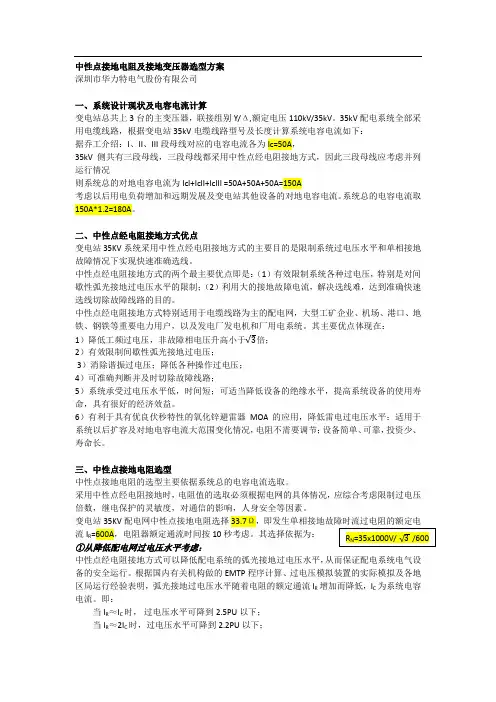
中性点接地电阻及接地变压器选型方案深圳市华力特电气股份有限公司一、系统设计现状及电容电流计算变电站总共上3台的主变压器,联接组别Y/Δ,额定电压110kV/35kV。
35kV配电系统全部采用电缆线路,根据变电站35kV电缆线路型号及长度计算系统电容电流如下:据乔工介绍:I、II、III段母线对应的电容电流各为Ic=50A,35kV侧共有三段母线,三段母线都采用中性点经电阻接地方式,因此三段母线应考虑并列运行情况则系统总的对地电容电流为IcI+IcII+IcIII =50A+50A+50A=150A考虑以后用电负荷增加和远期发展及变电站其他设备的对地电容电流。
系统总的电容电流取150A*1.2=180A。
二、中性点经电阻接地方式优点变电站35KV系统采用中性点经电阻接地方式的主要目的是限制系统过电压水平和单相接地故障情况下实现快速准确选线。
中性点经电阻接地方式的两个最主要优点即是:(1)有效限制系统各种过电压,特别是对间歇性弧光接地过电压水平的限制;(2)利用大的接地故障电流,解决选线难,达到准确快速选线切除故障线路的目的。
中性点经电阻接地方式特别适用于电缆线路为主的配电网,大型工矿企业、机场、港口、地铁、钢铁等重要电力用户,以及发电厂发电机和厂用电系统。
其主要优点体现在:1)降低工频过电压,非故障相电压升高小于√3倍;2)有效限制间歇性弧光接地过电压;3)消除谐振过电压;降低各种操作过电压;4)可准确判断并及时切除故障线路;5)系统承受过电压水平低,时间短;可适当降低设备的绝缘水平,提高系统设备的使用寿命,具有很好的经济效益。
6)有利于具有优良伏秒特性的氧化锌避雷器MOA的应用,降低雷电过电压水平;适用于系统以后扩容及对地电容电流大范围变化情况,电阻不需要调节;设备简单、可靠,投资少、寿命长。
三、中性点接地电阻选型中性点接地电阻的选型主要依据系统总的电容电流选取。
采用中性点经电阻接地时,电阻值的选取必须根据电网的具体情况,应综合考虑限制过电压倍数,继电保护的灵敏度,对通信的影响,人身安全等因素。
变压器选型手册变压器是电力系统中非常重要的元器件之一,其主要作用是将电压从一个水平变为另一个水平,并且在电路中传递电能。
在实际应用中,为了使变压器可以正常运行,需要对变压器进行选型。
本文将为大家介绍变压器选型的一些基本知识,以及选型时需要注意的一些问题。
一、选型前的基本知识1. 电压等级变压器的电压等级是指其额定电压的大小。
一般来说,变压器的电压等级应当与电网的电压等级相匹配,否则就会产生很大的问题。
2. 额定容量变压器的额定容量是指其正常运行时可以承载的最大负荷,单位为千伏安(kVA)。
3. 绕组形式变压器的绕组形式分为单相和三相两种,其中单相变压器适用于小容量的电力系统,而三相变压器适用于大型电力系统。
4. 冷却方式变压器的冷却方式一般分为自然冷却和强制风冷却两种。
在不同的应用环境下,需要选择不同的冷却方式。
二、选型时需要注意的问题1. 选型时需要考虑变压器的额定容量是否能够满足实际负载需求。
2. 选型时需要注意变压器的电压等级是否与电网的电压等级相匹配,否则容易造成电路故障。
3. 选型时需要考虑变压器的绕组类型,以及是否符合实际应用的要求。
4. 选型时需要考虑变压器的冷却方式,以及是否能够满足实际使用条件下的散热要求。
5. 选型时需要考虑变压器的安装位置,以及是否需要采取一些特殊措施来避免电磁干扰等问题。
三、变压器的选型流程1. 确定电压等级:根据实际需求,确定变压器的电压等级,以便对变压器的其他参数进行确定。
2. 确定额定容量:根据实际负载需求,确定变压器的额定容量,以便对变压器的其他参数进行确定。
3. 确定绕组形式:根据具体的应用需求,确定变压器的绕组形式。
4. 确定冷却方式:根据实际使用条件,确定变压器的冷却方式。
5. 确定其他参数:根据实际需求,确定变压器的其他参数,如铁芯材料、空载损耗等。
四、结语在进行变压器选型时,需要考虑多方面的因素,以确保变压器能够正常运行。
希望本文能够为各位读者提供一些帮助。
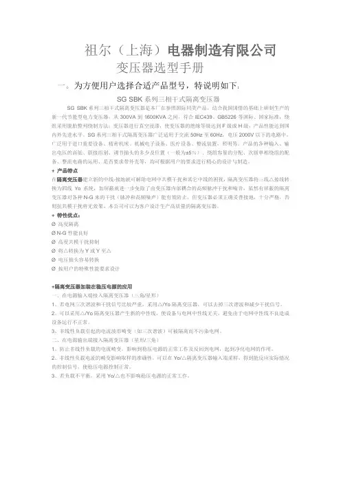
祖尔(上海)电器制造有限公司变压器选型手册一。
为方便用户选择合适产品型号,特说明如下:SG SBK系列三相干式隔离变压器SG SBK系列三相干式隔离变压器是本厂在参照国际同类产品,结合我国国情的基础上研制生产的新一代节能型电力变压器,从300VA到1600KVA之间,符合IEC439、GB5226等国际、国家标准,绕组采用脱胎整列绕制方法;变压器进行真空浸漆,使变压器的绝缘等级达到F级或H级,产品性能达到国内外先进水平。
SG系列三相干式隔离变压器广泛适用于交流50Hz至60Hz,电压2000V以下的电路中,广泛用于进口重要设备、精密机床、机械电子设备、医疗设备、整流装置,照明等。
产品的各种输入、输出电压的高低、联接组别、调节抽头的多少及位置(一般为±5%)、绕组容量的分配、次级单相绕组的配备、整流电路的运用、是否要求带外壳等,均可根据用户的要求进行精心的设计与制造。
+ 产品特点在隔离变压器建立新的中线-接地就可解除电网中共模干扰和其它中线的困扰,隔离变压器将三线△接线转换为四线Yo系统,加屏蔽就进一步免除了由变压器内部耦合的高频脉冲干扰和噪音,虽然有屏蔽的隔离变压器对各种N-G来的干扰(脉冲和高频噪声)能有效防止,但变压器必须正确妥善接地,十分严格,否则抗共模干扰将无效果。
本公司可以为客户设计生产高质量的隔离变压器。
+ 特性优点:Ø 高度隔离Ø N-G性能良好Ø 高度共模干扰抑制Ø 将△转换为Y或Y至△Ø 电压抽头容易转换Ø 按用户的特殊性能要求设计+隔离变压器加装在稳压电源的应用一、在电源输入端接入隔离变压器(三角/星形)1、若电网三次谐波和干扰信号比较严重,采用△/Yo隔离变压器,可以去掉三次谐波和减少干扰信号。
2、可以采用△/Yo隔离变压器产生新的中性线,使设备与电网中性线无关,避免由于电网中性线不良造成设备运行不正常。
500KV变电站主变压器的选型要领变压器是变电站较重要的电气设备之一,它的安全可靠运行关系到变电站乃至电网的安全稳定。
为保证变压器能够安全可靠运行,需要抓好选型、设计、制造、安装、运行维护以及检修各个环节。
其中较为关键的是要抓好源头,把好设计选型关。
选择变压器的结构型式、技术参数和性能指标,大体上应遵循以下两方面原则:一是要满足安装地所在电力系统方面的需求;二是要考虑变压器制造方面的可行性。
满足第一方面的要求这是不言而喻的,但不能不顾及第二方面的限制而过分强调第一方面,二者之间要统筹兼顾。
如果一味强调系统方面的要求,提出的技术参数和性能指标过高或过于苛刻,就可能使变压器结构复杂、制造难度增大,其后果轻者是无谓地增加制造成本,造成不必要的投资浪费;重者是将导致变压器可靠性降低,难以保证安全运行,给电网安全留下隐患。
由于结构的原因,变压器技术参数和性能指标之间互相关联,有些是不能同时兼顾的。
例如,空载损耗和负载损耗,不能要求两者都小,若空载损耗值取值较低,负载损耗则要相对较大,反之亦然。
还有高阻抗变压器,相对低阻抗变压器而言负载损耗总要高一些。
而对于三绕组变压器,不能对高—中、高—低和中—低绕组之间的短路阻抗全部做出规定,较多只能规定其中的两个。
这是因为当规定了任意两个短路阻抗值之后,余下的那个短路阻抗值就随之确定下来了。
在规定变压器技术参数和性能指标时要充分注意上述因素。
2 、500kV变电站主变压器选型原则2.1 容量的选择在国内已运行的50OkV变电站主变压器中。
整组容量有750MV A、800MV A、1000MV A和1200MV A 四种规格。
变压器容量的选择应考虑电网发展远景和变电站的较终规模。
总的来说,选择大容量变压器比选择多台小容量变压器要相对经济一些。
例如,一个变电站的较终规模为3组750MV A变压器,选择3组750MV A变压器不如选择1组1000MV A变压器和1组1200MV A变压器经济。
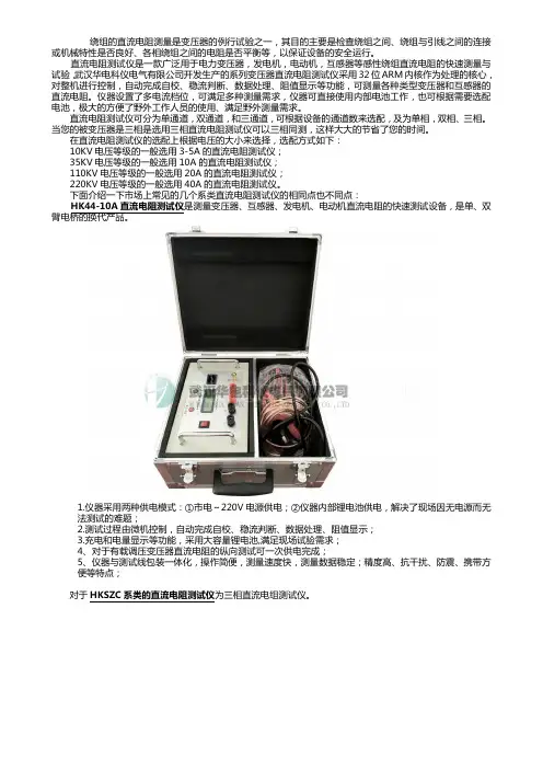
绕组的直流电阻测量是变压器的例行试验之一,其目的主要是检查绕组之间、绕组与引线之间的连接或机械特性是否良好、各相绕组之间的电阻是否平衡等,以保证设备的安全运行。
直流电阻测试仪是一款广泛用于电力变压器,发电机,电动机,互感器等感性绕组直流电阻的快速测量与试验,武汉华电科仪电气有限公司开发生产的系列变压器直流电阻测试仪采用32位ARM内核作为处理的核心,对整机进行控制,自动完成自校、稳流判断、数据处理、阻值显示等功能,可测量各种类型变压器和互感器的直流电阻。
仪器设置了多电流档位,可满足多种测量需求,仪器可直接使用内部电池工作,也可根据需要选配电池,极大的方便了野外工作人员的使用、满足野外测量需求。
直流电阻测试仪可分为单通道,双通道,和三通道,可根据设备的通道数来选配,及为单相,双相、三相。
当您的被变压器是三相是选用三相直流电阻测试仪可以三相同测,这样大大的节省了您的时间。
在直流电阻测试仪的选配上根据电压的大小来选择,选配方式如下:10KV电压等级的一般选用3-5A的直流电阻测试仪;35KV电压等级的一般选用10A的直流电阻测试仪;110KV电压等级的一般选用20A的直流电阻测试仪;220KV电压等级的一般选用40A的直流电阻测试仪。
下面介绍一下市场上常见的几个系类直流电阻测试仪的相同点也不同点:HK44-10A直流电阻测试仪是测量变压器、互感器、发电机、电动机直流电阻的快速测试设备,是单、双臂电桥的换代产品。
1.仪器采用两种供电模式:①市电~220V电源供电;②仪器内部锂电池供电,解决了现场因无电源而无法测试的难题;2.测试过程由微机控制,自动完成自校、稳流判断、数据处理、阻值显示;3.充电和电量显示等功能,采用大容量锂电池,满足现场试验需求;4、对于有载调压变压器直流电阻的纵向测试可一次供电完成;5、仪器与测试线包装一体化,操作简便,测量速度快,测量数据稳定;精度高、抗干扰、防震、携带方便等特点;对于HKSZC系类的直流电阻测试仪为三相直流电组测试仪。

电力设计手册500kva变压器选型
目前东北电力系统已建或待建500千伏变电所主变压器,选用普通型或自耦型两种型式。
对于主变压器型式的选择,涉及国家技术经济政策、设备制造、生产运行以及对所在电力系统通讯线路干扰、系统继电保护的影响等有关问题,须作技术经济论证方可确定。
本文就主变压器选用自耦型变压器有关技术经济问题作简要分析探讨,以供选型参考。
一、自耦变与普通变经济分析比较日前我国变压器制造厂已生产500千伏变压器的系列有:普通型三相式(双卷或三巷)240、360MVA;单相式(双卷或三卷)240、250MVA;自耦型三相式240、360。
500KVA变压器低压侧的额定电流约为750A,选TMY-3(60x6)+1x40x4的铜排或选用2根YJV-3x150+1x120的铜电缆,配电柜总开关选用1000A的框架断路器。
低压侧出线定义范围较广,这个“低压侧”是相对于变压器高压侧而言,没有电压等级概念,可以是10kv也可以是110kv。
出线是相对于“进线”而言,送入变电所的电源线称为进线,变电所供给负载的称为出线。
同理,发电厂送出线和母线上接到负载的也称为出线。
中性点接地电阻及接地变压器选型方案深圳市华力特电气股份有限公司一、系统设计现状及电容电流计算变电站总共上3台的主变压器,联接组别Y/Δ,额定电压110kV/35kV。
35kV配电系统全部采用电缆线路,根据变电站35kV电缆线路型号及长度计算系统电容电流如下:据乔工介绍:I、II、III段母线对应的电容电流各为Ic=50A,35kV侧共有三段母线,三段母线都采用中性点经电阻接地方式,因此三段母线应考虑并列运行情况则系统总的对地电容电流为IcI+IcII+IcIII =50A+50A+50A=150A考虑以后用电负荷增加和远期发展及变电站其他设备的对地电容电流。
系统总的电容电流取150A*1.2=180A。
二、中性点经电阻接地方式优点变电站35KV系统采用中性点经电阻接地方式的主要目的是限制系统过电压水平和单相接地故障情况下实现快速准确选线。
中性点经电阻接地方式的两个最主要优点即是:(1)有效限制系统各种过电压,特别是对间歇性弧光接地过电压水平的限制;(2)利用大的接地故障电流,解决选线难,达到准确快速选线切除故障线路的目的。
中性点经电阻接地方式特别适用于电缆线路为主的配电网,大型工矿企业、机场、港口、地铁、钢铁等重要电力用户,以及发电厂发电机和厂用电系统。
其主要优点体现在:1)降低工频过电压,非故障相电压升高小于√3倍;2)有效限制间歇性弧光接地过电压;3)消除谐振过电压;降低各种操作过电压;4)可准确判断并及时切除故障线路;5)系统承受过电压水平低,时间短;可适当降低设备的绝缘水平,提高系统设备的使用寿命,具有很好的经济效益。
6)有利于具有优良伏秒特性的氧化锌避雷器MOA的应用,降低雷电过电压水平;适用于系统以后扩容及对地电容电流大范围变化情况,电阻不需要调节;设备简单、可靠,投资少、寿命长。
三、中性点接地电阻选型中性点接地电阻的选型主要依据系统总的电容电流选取。
采用中性点经电阻接地时,电阻值的选取必须根据电网的具体情况,应综合考虑限制过电压倍数,继电保护的灵敏度,对通信的影响,人身安全等因素。
PDF 文件使用 "pdfFactory Pro" 试用版本创建 Taikai Electric Group Co., Ltd is a large-scale ent erpri se of researc hi ng & devel opi ng, m anu fac t u ri ng an d s el l i ng of c om p l et e eq ui p m en t s of p ow er t ran sm i s si on and di st r i bu t i on, up t o 55 0kV as w el l as a professional EPC contractor of transmission and transformation projects. Taikai Group with 1. 55 billion yuan of registered capital and 4.60 billion yuan of total capital, occupies 450,000 square meters of building area, and has more than 6700 employees. The group subordinated wit h 12 c om panies is ranked top 3 in the switchgear line of the whole country, with its comprehensive economic targets and the No. 1 position in Shandong province. The sales revenue has reached 1.05 billion USD last year. The day after the establishment, Taikai has been actively prom oting cultrue-advancingenterprise strategy, to im prove the company core com petence, and construct “animate enterprise, well-known products, and employee with great morale” development environment. The en t erpri se s pi ri t “Honest , Credi t , Prac tic al, and Innovative” and business , object ives “Pursuing Perfect and Repay Society.” Have been to the common corporate values and philosophy. Taikai uses the advanced MIS i nform ation system, and the design and m anufacture of products adopts CAD and CAM technology. All the subordi nated fi liales have passed t he ISO9001-2008 quality managem ent system,OHSAS18001-1999 occupational health and safety managem ent system, and ISO140012004 environmental management system, and “China Compulsory Certification”certification of l ow -vol t el ec t ri c appl i anc e and P CCC c erti fic at ion of nat ional energy produc ts. According to GB/T19001:2000 international quality standard, group has established strict quality management system. Our corporation perseveres in “intensive products and sincere desire service” quality service philosophy, pursues the im provem ent of product and service quality, and devotes our attention to supplying zero-defec t product s and zerodistance highly-efficient service. Taikai insists on independent innovation and technology strengthening enterprise, and the products consist of 5 catagories: switches, switch cubicles, transformers, automatic control, and wires and cables. It covers 6 voltage levels with 550kV and below, more than 180 kinds and over 2000 models. Adheres to the sustainable development informatization, innovative and hi gh t ec hnol ogy, professi onal izat ion, and economization, the group puresues the business pol i cy of Quali t y Devel opi ng Market and Integrity Casting Brand, and devotes itself to band m anagement strategy to build “TK” band. There are more than 30 kinds of products which fill in gaps of country and province, over 20 kinds of products listed in “Chinese National Key New Products Plan and Torch Plan” and ,more than 10 kinds of products have the honour to get national pantent. In rec ent years, Taikai has been chievi ng hypernom al and striding developm ent, and awarded as nationalwide “Key High and New Tech Enterprises” “Nationalwide Torch Plan , Key Enterprise of Tai’an Transm ission and Transformation Products Manufacture Base” , “Nationalwide Enterprise Adhering to Heavy Credi t of Cont ract s” , “Nat ional Model Harmonious Enterprise in Labor Relation” one , of the fifty powerful enterprises in paying taxes by mechanical industry of Shandong province, one of the ten prop enterprises in economy of Tai’an city, the “civilized unit” by Shandong prov i nc e for c ont i nu ous fou r years, t he advanced unit i n m aki ng peopl e ric h and vitalizing Shandong province. According to the category of transmission and t rans for m at i on eq ui p m ent s , Tai k ai has establ ished 12 w holly-owned subsidiaries, which are all enterprises above designated size. Standing one the area of over 1,333, 333m 2 , with the professional and dedicated at t i t u d e, Tai k ai p eo p l e s p eed u p t h e development step of these 12 companies. W e are trying our best to promote“Taikai” from equipment m anufacture to overall design and installation of substations, and the dom estic l eadi ng and i nt ernat i onal advanc ed transmission and transformation manufacture base.Enterprise Spirit: Honest, Credit, Practical, and Innovative Enterprise Tenet: Pursuing perfect to repay society Operation Principle: Maintaining the domestic leading position, and Achieve world top-ranking Quality Policy: For all the positions, prevention should come first, and improve the quality management system continuously. To provide the electric system excellent product with better performance, quality and price to make more contributes to the society.PDF 文件使用 "pdfFactory Pro" 试用版本创建 Shandong Taikai Power Engineering Co., Ltd (hereinafter briefed as TKPE), subordinated to Taikai Electric Group, is an economic entity of independent corporation, and enjoys right in foreign trade & power engineering business. TKPE is the leading company in supplying complete equipments for high-volt power transmission and transformation substation, including: Transformer, GIS, Circuit Breaker, Disconnector, Current Transformer, Voltage Transformer, Switch Cubicle, Prefabricated Substation, and Integrated Protection Devices. TKPE is an EPC c ontractor of power transmission and transformation substation projects and the incorporated facilities for thermal station, hydropower station and combined cycle power station and the supplying of professional international trade service, which is approved by China Ministry of Construction. TKPE possesses credential of import and export enterpris, economic cooperation concerning foreign interests, and construction permit of contracting installation, maintenance, and commission. TKPE adopts firs t-c las s engineer management technology, internal computer network, internet, CAD drawing software and comprehensive management software. “TK” brand complete products, reputable all over the world, have been exported to Poland, Russia, Sudan, Vietnam, Myanmar, Turkey, Pakistan, Kazakhstan, Mongolia, Nigeria, Algeria, Nepal, India and etc. TKPE would establish and perfect the quality control and internal management system for a project under the condition of guarantying the quality and reliability of the equipment to meet customer’s requirements in safety, sanitary, environment protection, risk control and etc. TKPE sincerely wishes to cooperate with y ou f or m u t ual b en ef it an d f u r th er development, we promise to provide you qualified product and considerate service.PDF 文件使用 "pdfFactory Pro" 试用版本创建 TRANSFORMER10~35kV Oil-immersed Power Transformer SC(B) Serial Epoxy Casting Dry Transformer SCBZ9-315~2500/10 Serial Epoxy Casting Dry Transformer with OLTCINSTRUMENT TRANSFORMER1 7LVQB-35~500 Series SF6 Current Transformer Oil-immersed Vertical Current Transformer LVB(T)-35~220 Oil-immersed Inverted Current Transformer51 54 57 60 63 65 67 68 6912 13JDQXF-35~220 Voltage Transformer TYD-35~220 Capacitor Voltage Transformer JLSQ-10(35) Combined Transformer Metallic Oxide Lightning Arrester Compound-Bushing Zero-Clearance LA Porcelain Bushing LASG10 Type-H Insulating Dry TransformerSCBH10 Series Amorphous Alloy Dry Type Transformer15 35~500kV Oil-immersed Power Transformer Commutator Transformer17 28 29Furnace TransformerREACTORBKGKL Shunt Reactor30 32 41 46 48 50CKGKL Dry-type Air-lore Reactor XKGKL Current Limiting Reactor Dry-type core Reactor LKGKL Filter Reactor 330kV,550kV Oil-Immersed ReactorPDF 文件使用 "pdfFactory Pro" 试用版本创建 10~35kVOil-immersed Power Transformer1 OverviewThis product applies to 3-phases, 50Hz, 35kV and below power system, and is the main transformation equipment of small and medium enterprise. The product has widely used in agricultural and industrial power distribution, power and lighting. The company draw on advanced technology, using new materials and optimized design to make the products more reasonable, the electric strength, mechanical strength, and heat dissipation capacity of the product to be significantly improved. The product meets GB1094.1~2-1996, GB1094.3~4-2003, GB/T6451-1999.2 Model and DefinitionsS(F)Z □-M- □/ □ Rated voltage (kV) Rated power (kVA) Full seal Design series no. On-load switch Cooling method (air cooling) Number of phase (three phases)3 Service and Installation ConditionsAltitude:≤1000m Environment temperature:The maximum temperature:+40℃,the maximum monthly average temperature:+30℃,the maximum yearly average temperature:+20℃,The lowest temperature:-45℃ (3) Power demand:approximate sine wave, three-phase symmetrical (4) Installation site:outside or inside, the environment has no significant contamination Note: it should be explained if the transformer is used in special conditions in order.4 Main ParametersS9 serial 35kV oil-immersed power transformer with OCTCVoltage group and tap Type S9-50 S9-80 S9-100 S9-125 S9-160 S9-200 S9-250 S9-315 S9-400 S9-500 S9-630 S9-800 S9-1000 S9-1250 S9-1600 S9-2000 S9-2500 35 38.5 ± 5% or 0.4 Yyn0 or Dyn11 HV HV tap LV Vector No load group loss 0.21 0.28 0.29 0.34 0.36 0.43 0.51 0.61 0.73 0.86 1.04 1.23 1.44 1.76 2.12 2.65 2.96 Load loss 1.27/1.21 1.81/1.72 2.12/2.02 2.5/2.38 2.97/2.83 3.5/3.33 4.16/3.96 5.01/4.77 6.05/5.76 7.28/6.93 8.28 9.90 12.15 14.67 17.55 20.7 24.5 No load Short-circuit Weight current impedance 2.0 1.8 1.8 1.70 1.60 1.50 1.40 1.30 1.30 1.20 1.10 1.00 1.00 0.90 0.80 0.70 0.60 6.5 900 1020 1100 1220 1320 1580 1780 1795 2230 2460 2970 3595 4010 4795 5760 6000 6830 Dimension (mm) L 1220 1220 1220 1220 1810 1990 2010 2020 2020 2040 2320 2365 2390 2470 2660 2670 2500 W 950 1070 1070 1250 1020 1020 1120 1120 1200 1220 1190 1510 1520 1530 1600 1650 3000 H 1710 1770 1800 1900 1930 2080 2130 2200 2290 2400 2410 2365 2425 2610 2650 2730 2700 1070 × 1070 820 × 820 660 × 660 Gauge(mm)± 2 × 2.5% 0.69Note: (1) For the transformer capacity of 500kVA and below, the load loss values of table slash top apply to Dyn11 vector group, the load loss values of table bottom apply to Yyn0 vector group. (2) Dimensions only for reference. (3) Making special parameter power transformer according to customer’s demand.P 1.PDF 文件使用 "pdfFactory Pro" 试用版本创建 S11 type 35kV oil-immersed power transformer with OCTCVoltage group and tapTypeHVHV tapLVVector No load group loss 0.17 0.22 0.24 0.27 0.29 0.34 0.41 0.49 0.58 0.69 0.83 0.98 1.15 1.41 1.7 1.98 2.35Load loss 1.21/1.15 1.72/1.63 2.01/1.92 2.38/2.26 2.82/2.69 3.33/3.16 3.95/3.76 4.76/4.53 5.75/5.47 6.92/6.58 7.87 9.41 11.54 13.94 16.68 19800 23000No load Short-circuit Weight current impedance 1.6 1.44 1.44 1.36 1.28 1.2 1.12 1.04 1.04 0.96 0.88 0.80 0.80 0.72 0.64 0.56 0.48 6.5 785 920 1100 1245 1470 1510 1615 2010 2170 2565 2980 3680 4490 4860 5580 6090 6900Dimension (mm)L W HGauge(mm)S11-50 S11-80 S11-100 S11-125 S11-160 S11-200 S11-250 S11-315 S11-400 S11-500 S11-630 S11-800 S11-1000 S11-1250 S11-1600 S11-2000 S11-2500 35 ± 5% or 0.4 38.5 ± 2 × 2.5% 0.69 Yyn0 or Dyn111070 1090 1165 1265 1310 1350 1400 1640 1720 2030 2070 2220 2370 2390 2430 2550 2630830 850 900 1080 1080 1100 1120 1130 1140 1160 1220 1260 1290 1340 1420 1700 18001770 1790 1870 1950 1970 1980 2040 2080 2120 2160 2240 2340 2440 2580 2620 2700 3050 1070 × 1070 820 × 820 660 × 660(1) For the transformer capacity of 500kVA and below, the load loss values of table slash top apply to Dyn11 vector group, the load loss values of table bottom apply to Yyn0 vector group. (2) Dimensions only for reference. (3) Making special parameter power transformer according to customer’s demand. S9 type 10kV oil-immersed power transformer with OCTCVoltage group and tapTypeHVHV tapLVVector No load group loss 0.13 0.17 0.20 0.25 0.29 0.34 0.40Load loss 0.63/0.60 0.91/0.87 1.09/1.04 1.31/1.25 1.58/1.50 1.89/1.80 2.31/2.20 2.73/2.60 3.20/3.05 3.83/3.65 4.52/4.30 5.41/5.15 6.20 7.50 10.3 12.0 14.5 19.8 23.0No load Short-circuit Weight current impedance 2.3 2.0 1.9 1.9 1.8 1.7 1.6 1.5 1.4 1.4 1.3 1.2 1.1 1.0 1.0 0.9 0.8 0.7 0.6 4.0 320 400 440 490 560 670 770 920 1110 1260 1550 1780 2240 2495 2930 3380 4090 5280 6370Dimension (mm)L W HGauge(mm)S9-30 S9-50 S9-63 S9-80 S9-100 S9-125 S9-160 S9-200 S9-250 S9-315 S9-400 S9-500 S9-630 S9-800 S9-1000 S9-1250 S9-1600 S9-2000 S9-2500 6 6.3 10 11 Yyn0 ± 5% or 0.4 or Dyn111050 1100 1110 1110 1110 1190 1250 1250 1540 1560 1600 1630 1760 2135 2140 2200 2380 2420 2460610 770 770 780 790 800 830 840 990 1010 1040 1200 1230 1250 1370 1370 1385 1450 27001080 1120 1150 1210 1220 1370 1400 1440 1500 1530 1590 1650 1760 1835 1945 1990 2080 2405 2600 1070 × 1070 820 × 820 660 × 660 550 × 550 400 × 4000.48 0.56 0.67 0.80 0.96 1.20 1.40 1.70 1.95 2.40 2.60 3.000.69 10.5 ± 2 × 2.5%Note: (1) For the transformer capacity of 500kVA and below, the load loss values of table slash top apply to Dyn11 vector group, the load loss values of table bottom apply to Yyn0 vector group. (2) Dimensions only for reference. (3) Making special parameter power transformer according to customer’s demand.P 2.PDF 文件使用 "pdfFactory Pro" 试用版本创建 SZ9 type 10kV oil-immersed power transformer with OLTCVoltage group and tap Type SZ9-100 SZ9-125 SZ9-160 SZ9-200 SZ9-250 SZ9-315 SZ9-400 SZ9-500 SZ9-630 SZ9-800 SZ9-1000 SZ9-1250 SZ9-1600 6 6.3 10 10.5 11 ± 4 × 2.5%0.4 0.69HVHV tapLVVector No load group loss 0.29 0.34 0.40 0.48 0.56 Yyn0 or Dyn11 0.67 0.80 0.96 1.20 1.40 1.70 1.95 2.40Load loss 1.58 1.89 2.31 3.06 3.6 4.32 5.22 6.21 7.65 9.36 10.98 13.05 15.57No load Short-circuit Weight current impedance 1.8 1.7 1.6 1.5 1.4 1.4 1.3 1.2 1.1 1.0 1.0 0.9 0.8 4.5 4.0 880 960 1080 1200 1400 1600 1870 2190 2620 3100 3660 4160 4880Dimension (mm)L W HGauge(mm)1630 1660 1710 1740 1940 1980 2050 2060 2590 2620 2650 2720 2880800 850 870 870 880 900 1000 1070 1130 1290 1380 1410 14901370 1380 1410 1450 1560 1610 1680 1760 1970 2070 2120 2190 2210 820 × 820 660 × 660Note: (1) Above parameter applies to 400V of LV. (2) Dimensions only for reference. (3) Making special parameter power transformer according to customer’s demand.S9-M type 10kV oil-immersed power transformer with OCTCVoltage group and tapTypeHVHV tapLVVector No load group loss 0.13 0.17 0.20 0.25 0.29 0.34 0.40Load loss 0.63/0.60 0.91/0.87 1.09/1.04 1.31/1.25 1.58/1.50 1.89/1.80 2.31/2.20 2.73/2.60 3.20/3.05 3.83/3.65 4.52/4.30 5.41/5.15 6.20 7.50 10.3 12.0 14.5 19.8 23.0No load Short-circuit Weight current impedance 2.3 2.0 1.9 1.9 1.8 1.7 1.6 1.5 1.4 1.4 1.3 1.2 1.1 1.0 1.0 0.9 0.8 0.7 0.6 4.5 4.0 360 440 480 530 600 680 790 900 1080 1250 1500 1700 2180 2395 2850 3370 4060 5160 6390Dimension (mm)L W HGauge(mm)S9-M-30 S9-M-50 S9-M-63 S9-M-80 S9-M-100 S9-M-125 S9-M-160 S9-M-200 S9-M-250 S9-M-315 S9-M-400 S9-M-500 S9-M-630 S9-M-800 S9-M-1000 S9-M-1250 S9-M-1600 S9-M-2000 S9-M-25006 6.3 10 10.5 11820 870 880 900 910 950 990 1250 1280 1370 1440 1440 1600 1715 1910 1980 1980 2100 2180670 670 670 680 690 700 720 730 750 780 810 820 860 960 1250 1280 1280 1450 1490990 1030 1060 1120 1170 1190 1210 1320 1380 1400 1470 1530 1570 1585 1700 1740 1830 2020 2230 1070 × 1070 820 × 820 660 × 660 550 × 550 400 × 400Yyn0± 5% or ± 2× 2.5% 0.4 0.690.48 0.56 0.67 0.80 0.96 1.20 1.40 1.70 1.95 2.40 2.60 3.00or Dyn11Note: (1) For the transformer capacity of 500kVA and below, the load loss values of table slash top apply to Dyn11 vector group, the load loss values of table bottom apply to Yyn0 vector group. (2) Dimensions only for reference. (3) Making special parameter power transformer according to customer’s demand.P 3.PDF 文件使用 "pdfFactory Pro" 试用版本创建 S11 type 10kV oil-immersed power transformer with OCTCVoltage group and tapType S11-30 S11-50 S11-63 S11-80 S11-100 S11-125 S11-160 S11-200 S11-250 S11-315 S11-400 S11-500 S11-630 S11-800 S11-1000 S11-1250 S11-1600 S11-2000 S11-2500 6 6.3 10 10.5 11HVHV tapLVVector No load group loss0.10 0.13 0.15 0.18 0.20 0.24 0.28Load loss0.63/0.60 0.91/0.87 1.09/1.04 1.31/1.25 1.58/1.50 1.89/1.80 2.31/2.20 2.73/2.60 3.20/3.05 3.83/3.65 4.52/4.30 5.41/5.15 6.20 7.50 10.3 12.0 14.5 19.8 23.0No load Short-circuit Weight current impedance1.84 1.6 1.52 1.52 1.44 1.36 1.28 1.20 1.12 1.12 1.04 0.96 0.88 0.8 0.8 0.72 0.64 0.56 0.48 4.5 4.0 320 410 470 510 570 700 800 950 1080 1290 1530 1800 2330 2680 3130 3650 4430 4730 6100Dimension (mm)L 1050 1100 1110 1110 1110 1190 1250 1250 1540 1560 1460 1520 1740 2120 2170 2340 2470 2130 2270 W 610 770 770 780 790 800 830 830 990 1010 1030 1190 1230 1240 1420 1450 1510 1710 2100 H 1080 1150 1180 1230 1240 1410 1430 1490 1510 1580 1600 1670 1840 1940 2010 2040 2290 2550 2600Gauge(mm)400 × 400Yyn0 ± 5%or ± 2× 2.5%0.4 0.690.34 0.40 0.48 0.57 0.68 0.81 0.98 1.15 1.36 1.64 1.98 2.35550 × 550or Dyn11660 × 660820 × 820Note: (1) For the transformer capacity of 500kVA and below, the load loss values of table slash top apply to Dyn11 vector group, the load loss values of table bottom apply to Yyn0 vector group. (2) Dimensions only for reference. (3) Making special parameter power transformer according to customer’s demand. S11-M type 10kV oil-immersed power transformer with OCTCVoltage group and tapTypeHVHV tapLVVector No load group loss 0.10 0.13 0.15 0.18 0.20 0.24Load loss 0.63/0.60 0.91/0.87 1.09/1.04 1.31/1.25 1.58/1.50 1.89/1.80 2.31/2.20 2.73/2.60 3.20/3.05 3.83/3.65 4.52/4.30 5.41/5.15 6.20 7.50 10.3 12.0 14.5No load Short-circuit Weight current impedance 1.84 1.6 1.52 1.52 1.44 1.36 1.28 1.20 1.12 1.12 1.04 0.96 0.88 0.8 0.8 0.72 0.64 4.5 4.0 360 485 500 540 610 710 810 960 1050 1280 1430 1690 2270 2580 3060 3560 4470Dimension (mm)L W HGauge(mm)S11-M-30 S11-M-50 S11-M-63 S11-M-80 S11-M-100 S11-M-125 S11-M-160 S11-M-200 S11-M-250 S11-M-315 S11-M-400 S11-M-500 S11-M-630 S11-M-800 S11-M-1000 S11-M-1250 S11-M-1600 6 6.3 10 10.5 11 ± 5%or ±2× 2.5% 0.4 0.69 Yyn0 or Dyn11820 870 880 900 910 950 990 1030 1320 1370 1410 1440 1580 1700 1840 1980 2000670 670 670 680 690 700 720 730 750 780 790 800 870 960 1220 1330 1340990 1060 1090 1140 1180 1220 1240 1310 1330 1400 1420 1490 1650 1690 1760 1790 1910 820 × 820 660 × 660 550 × 550 400 × 4000.28 0.34 0.40 0.48 0.57 0.68 0.81 0.98 1.15 1.36 1.64Note: (1) For the transformer capacity of 500kVA and below, the load loss values of table slash top apply to Dyn11 vector group, the load loss values of table bottom apply to Yyn0 vector group.(2) Dimensions only for reference.(3) Making special parameter power transformer according to customer’s demand.P 4.PDF 文件使用 "pdfFactory Pro" 试用版本创建 S11-M.R serial 10kV oil-immersed power transformer with OCTCVoltage group and tapTypeHVHV tapLVVector No load group loss 0.10 0.13 0.15 0.18Load loss 0.60 0.87 1.04 1.25 1.50 1.80 2.20 2.60 3.05 3.65 4.30 5.10 6.20No load Short-circuit Weight current impedance 1.00 0.90 0.80 0.70 0.60 0.60 0.55 0.55 0.50 0.50 0.45 0.45 0.40 4.5 4.0 350 440 510 550 650 730 810 960 1110 1310 1630 1880 2280Dimension (mm)L W HGauge(mm)S11-M.R-30 S11-M.R-50 S11-M.R-63 S11-M.R-80 S11-M.R-100 S11-M.R-125 S11-M.R-160 S11-M.R-250 S11-M.R-315 S11-M.R-400 S11-M.R-500 S11-M.R-630 6 6.3 10 11 ± 5%or ± 2 × 2. 5% 0.4 0.69 Yyn0 or Dyn111040 1080 1110 1130 1150 1180 1200 1250 1310 1390 1460 1490 1580640 640 650 660 660 670 680 700 720 770 800 810 840990 1050 1100 1150 1210 1250 1280 1390 1420 1480 1550 1620 1700 660 × 660 550 × 550 400 × 4000.20 0.24 0.27 0.33 0.40 0.48 0.57 0.68 0.81S11-M.R-200 10.5Note: (1) Above parameter applies to 400V of LV. (2) Dimensions only for reference. (3) Making special parameter power transformer according to customer’s demand.SH11-M serial 10kV oil-immersed power transformer with OCTCVoltage group and tapTypeHVHV tapLVVector No load group loss 0.033 0.043 0.060 0.075 0.085 0.100Load loss 0.60 0.87 1.25 1.50 1.80 2.20 2.60 3.05 3.65 4.30 5.10 6.20 7.50 10.3 12.0 14.5 17.4No load Short-circuit Weight current impedance 1.50 1.40 1.20 1.10 1.00 0.90 0.90 0.80 0.80 0.70 0.70 0.60 0.60 0.50 0.40 0.40 0.40 5.5 4.5 4.0 480 620 800 880 955 1095 1240 1450 1680 2070 2330 2800 3340 3555 4270 4860 6160Dimension (mm)L W HGauge(mm)SH11-M-30 SH11-M-50 SH11-M-80 SH11-M-100 SH11-M-125 SH11-M-160 SH11-M-200 6 ± 5%or ±2× 2.5% 0.4 0.69 Dyn11 SH11-M-250 6.3 SH11-M-315 10 SH11-M-400 10.5 SH11-M-500 11 SH11-M-630 SH11-M-800 SH11-M-1000 SH11-M-1250 SH11-M-1600 SH11-M-2000885 1215 1310 1320 1360 1410 1465 1540 1580 1705 1655 1840 1950 2110 2290 2040 2330780 830 840 885 920 910 910 910 910 945 1000 1140 1170 1250 1370 1410 16501005 1035 1125 1060 1095 1140 1200 1240 1300 1360 1400 1415 1485 1420 1530 1560 1680 1070 × 1070 820 × 900 660 × 660 550 × 6600.120 0.140 0.170 0.200 0.240 0.320 0.380 0.450 0.530 0.630 0.750Note: (1) Above parameter applies to 400V of LV. (2) Dimensions only for reference. (3) Making special parameter power transformer according to customer’s demand.P 5.PDF 文件使用 "pdfFactory Pro" 试用版本创建 5 Structure and FeaturesCore:the core lamination made from high permeability sheet is cutted on GEORG-line imported from Germany, using step-by-step lapped joint and colligating structure, and meets the demand of low no load loss and low noise level. Winding:using low resistivity oxygen-free copper, and linking the reasonable transposition of the parallel wire, load loss of transformer is greatly reduced. Tank:using barrel structure and large corrugated. The company adopts the technology of carbon dioxide protection, selects sealing material perfectly, machines the seal surface and carries on a strict leak detection procedure. All these assure that the transformer are leakage-free. The new style radiators and coolers improve external appearance quality of transformer greatly. Surface treatment and coating: fine processing to the oil tank surface and using special anti-fouling paint, all these assure that the surface coating does not fall off, and the steel structure does not rust away.6 Outline and Installation Size1.Oil level indicator 2.High voltage bushing 3.LV bushing 4.OCTC 5.LV neutral bushing 6.Pressure relief valve 10kV Oil-immersed Power TransformerP 6.PDF 文件使用 "pdfFactory Pro" 试用版本创建 SC(B) Serial Epoxy Casting Dry Transformer1 OverviewThis serial epoxy casting dry transformer uses high-quality materials, scientific formula and advanced technology. The product has high reliability and long life characteristics. It can be configured with different levels of protection, or does not configure the shell casing depending on the use of the environment. It applies to high-rise buildings, commercial centers, airports, tunnels, chemical plants, nuclear power plants, ships and other important or special place. Using dry-type transformers proprietary technology and casting stress control technology, controlling casting dry-type transformers internal insulation in the best condition, ensures key performance of dry-type transformers. The product calculated field strength during the design process. Make the various components field strength to 75% or less of insulating materials by adjusting the relevant parameters and ensure the product's advanced technical performance. Leading rated performance to relevant links in advance during the product design, so that the product design inputed has included relevant requirements and made the output meet the need.2 Model and DefinitionsS C(B)□ - □ / □Voltage class (kV) Rated capacity (kVA) Design series no. Opal winding circles Castresin type transformer Three-phase transformer3 Service and Installation ConditionsAltitude:1000m Environment temperature The maximum temperature:+40 The maximum monthly average temperature:+30 The maximum yearly average temperature:+20 The lowest yearly temperature:-5 Power voltage waveform: power voltage waveform approximate sine. The symmetry of multi-phase power voltage: connected power voltage of multi-phase transformershould be approximately symmetrical. Protection class:IP00, IP20, IP23. Cooling style:air cold and forced air-cooled Note: it should be explained if the transformer is used in special conditions in order.4 Main ParametersThe core using high-quality cold-rolled silicon steel sheet, 45 degrees inclined ladder joint structure, and cutting processes, the core for curing and surface with the insulating resin sealing process. HV coil using high-quality F insulating copper wire and internationally advanced insulation materials, and the large capacity coil equipped with cooling along the axial airway. LV coil using foil structure, the coil end sealed curing resin after winding, avoiding variety of foreign matter and moisture to enter. Safety, anti-fire, no pollution, it can be directly run the load center.P 7.PDF 文件使用 "pdfFactory Pro" 试用版本创建 Using Germany HTT technical, high mechanical strength, and high anti-short-circuit capability. Partial discharge is small. High thermal stability, high reliability and long service life. Low loss, low noise, energy-saving effect obviously, and maintenance-free. Good moisture-proof performance, and adapt to high humidity and other harsh environments running. Equipped with improved temperature detection and protection systems. Small size, light weight, occupies less space, and lower installation costs. SC10-5~100/10 serial epoxy casting dry transformer SC(B)9-125~2500/10 serial epoxy casting dry transformer SC(B)10-125~2500/10 serial epoxy casting dry transformer SC(B)9-30~2500/35 serial epoxy casting dry transformer.5 Outline DimensionsSC10-5~100/10 epoxy casting dry transformerOutline Dimensions Type SC10-5/10 SC10-10/10 SC10-15/10 SC10-20/10 SC10-25/10 SC10-30/10 SC10-50/10 SC10-63/10 SC10-80/10 SC10-100/10 a 515 515 575 575 585 585 585 785 785 855 b 400 400 400 400 400 400 400 500 500 500 c 300 300 400 400 400 400 400 400 400 550 d 300 300 300 300 300 300 300 400 400 400 j 175 175 195 195 200 205 210 265 265 290 h 540 550 550 550 580 580 655 800 800 860 k 100 100 110 110 110 110 110 100 100 150a:ontic length b:ontic width c:ontic landscape interface dimension d:ontic Longitudinal installation dimensions j:mo k The LV outgoing line spacing distance h: this data is outer dimension for normal product,which will alter if ording data changes,Parties through consultation. Reference SpecificationsRated Power (kVA) 30 50 63 80 100 H.V(kV) 6 6.3 6.6 10 10.5 11 Voltage Combination Tapping Range L.V(kV) Connection Symbol Short circuit No-Load impedance Loss (%) (W) 220 ± 5% ± 2 × 2.5% 0.4 Y yn0 D yn11 310 4 380 410 450 Load Losses 75℃(W) 650 920 1050 1270 1450 Load Losses 120℃(W) 750 1060 1202 1460 1670 No-Load Current (%) 2 1.5 1.5 1.1 1.1 LPA Noise Level (dB) 45 45 46 46 46 Weight (kg) 225 300 470 500 620P 8.PDF 文件使用 "pdfFactory Pro" 试用版本创建 SC(B)9-125~2500/10 Epoxy Casting Dry TransformerType SC(B)9-125/10 SC(B)9-160/10 SC(B)9-200/10 SC(B)9-250/10 SC(B)9-315/10 SC(B)9-400/10 SC(B)9-500/10 SC(B)9-630/10 SC(B)9-630/10 SC(B)9-800/10 SC(B)9-1000/10 SC(B)9-1250/10 SC(B)9-1600/10 SC(B)9-2000/10 SC(B)9-2500/10 Outline Dimensions c d 550 550 550 660 660 660 660 660 660 660 820 820 820 820 820 550 550 550 550 720 720 720 720 720 720 820 820 1070 1070 1070 Shield cap m 550 550 660 660 660 660 660 660 660 820 820 820 820 820 820a 990 1050 1100 1140 1180 1220 1240 1270 1400 1400 1460 1570 1720 1800 1950b 650 650 650 650 820 820 820 820 820 820 920 920h 1050 1080 1130 1150 1250 1300 1350 1410 1400 1460 1580 1620 1860 2050 2200A 1550 1550 1550 1550 1550 1550 1700 1700 1700 1700 1800 1950 2000 2100 2400B 1200 1200 1200 1200 1200 1200 1300 1300 1300 1300 1400 1400 1500 1500 1500n 1150 1150 1150 1150 1150 1150 1250 1250 1250 1250 1350 1350 1450 1450 1450H 1800 1800 1800 1800 1800 1800 1900 1900 1900 1900 1900 2000 2200 2400 26001200 1270 1270a:ontic length b:ontic width c:ontic landscape interface dimension d:ontic Longitudinal installation dimensions h:ontic height, A:outskin’s length, B: outskin’s width, m:outskin’s landscape interface dimension, n:outskin’s Longitudinal interface dimension, H:outskin’s heightReference SpecificationsRated Power (kVA) 125 160 200 250 315 400 500 630 630 800 1000 1250 1600 2000 2500 6 6.3 6.6 10 10.5 11 6 ± 5% ± 2 × 2.5% 0.4 Y yn0 D yn11 4 Voltage Combination Short circuit Load No-Load Connection Losses impedance Tapping Loss (W) H.V.(kV) L.V(kV) Symbol 75℃(W ) (%) Range 530 170 610 700 810 990 1100 1300 1500 1460 1700 1990 2350 2750 3400 4000 1960 2330 2540 3200 3680 4500 5420 5500 6427 7510 8960 10829 13360 15870 Load No-Load LPA Noise Weight Current Losses Level (dB) (Kg) (%) 120℃(W ) 1960 2250 2680 2920 3670 4220 5170 6220 6310 7360 8610 10260 12400 15300 18180 1 0.9 0.9 0.9 0.8 0.8 0.7 0.6 0.6 0.5 0.5 0.4 0.4 0.3 0.3 46 46 47 48 48 49 49 49 50 51 52 53 54 55 56 650 850 870 1100 1400 1550 1700 2200 2300 2500 2900 3550 4600 5500 6200P 9.PDF 文件使用 "pdfFactory Pro" 试用版本创建 。
变压器是利用电磁感应的原理来改变交流电压的装置。
主要功能有:电压变换、电流变换、阻抗变换、隔离、稳压(磁饱和变压器)等,是电路中最常见的部分。
要想让电路达到稳定就要选择合适的变压器。
下面为你介绍变压器选用中的几点问题:一、变压器的制作中,线圈的机器绕制和手工绕制各有什么优缺点?机器绕制变压器的优点是效率高且外观成形漂亮,但绕制高个子小洞眼的环型变压器却比较麻烦,而且在绝缘处理工艺的可靠性方面反不如手工绕制到位。
手工绕制可以将变压器的漏磁做得非常小,其在绕制过程中能针对线圈匝数的布局随时予以调整,所以真正的Hi–END变压器一定是纯手工绕制,纯手工绕制的唯一缺点是效率低、速度慢。
二、环型、EI型、R型、C型几种电源变压器哪一种最好?它们各有其优缺点而不存在谁最好之说,所以严格来讲哪一种变压器都可以做得最好。
从结构上来讲,环型能够做到漏磁最小,但声音听感方面EI型则可以把中频密度感做得更好一些。
单就磁饱和而言,EI型要比环型强,但在效率上则环型又优于EI型。
尽管如此,其问题的关键还是在于你能不能扬长避短而将它们各自的优点充分发挥出来,而这才是做好变压器的最根本。
目前的进口放大器中,环型变压器的应用仍然是主流,这基本说明了一个问题。
发烧友对变压器的评价要客观公正,你不能拿一个没做好的东西作参考而说它不好。
有人说环型变压器容易磁饱和,那你为什么不去想办法把它做到不容易磁饱和?而原本通过技术手段是可以做到这一点的。
不下足功夫或者一味地为了省成本,那它当然就容易磁饱和了。
同理,只要你认真制作,EI型变压器的效率也是能做到很高的。
变压器的品质好坏对声音的影响很大,因为变压器的传输能量与铁芯、线圈密切关联,其传递速率对声音的影响起决定性作用。
像EI型变压器,人们通常觉得它的中频比较厚,高频则比较纤细,为什么呢?因为它的传输速度相对比较慢。
而环型呢?低频比较猛,中高频则又稍弱一点,为什么?因为它传输速度比较快,但是如果通过有效的结构改变,你就可以把环型和EI型都做得非常完美,所以关键还是要看你怎么做。
农业机械化与电气化大型发电机中性点配电变压器电阻接地选型设计张健(南京汽轮电机(集团)有限责任公司,江苏南京210000)摘要:目前,我国投入使用的大型发电机多采用中性O经配电变压器电阻接地的方式。
大型发电机的定子绕组对地电容较大,在出现定子单相接地故障时电容的电流也十分庞大,通过中性o经配电变压器的方式可以实现对故障电流的有效限制。
本文将对大型发电机中性o配变电压器电阻接地的选型设计进行探讨研究。
关键词:大型发电机;配电变压器;电阻;接地1大型发电机中性点配电变压器电阻接地选型设计应遵循的原则11负载电阻设计应遵循的原则对于采用经配电变压器电阻接地这种方法的大型发电机而言,为了有效抑制可能出现的间歇性单相接地故障重燃弧引发的尖峰过电压现象,只有在负载电阻折算到一次侧后的阻值与发电机定子侧系统对地电容的容抗保持基本相等时,才能将该电压值控制在2.6倍的相电压峰值范围内。
但在一切特殊的情况下,电阻值的选择会突破这一范围的限制。
上文中提到的电容主要指的是发电机定子绕组和定子绕组直接相连的设备对地电容,其中有发电机出口至其他连接设备之间连线的对地电容、发电机定子绕组的对地电容、励磁变高压侧绕组的对地电容、断路器对地电容等%1.2接地变压器电压变比的设计原则当大型发电机出现金属性接地故障之后,其中性点电压将在短时间内被抬高到相电压,为了应对这一情况,接地变压器高压侧的电压通常设定为发电机的额定相电压或是线电压。
此外,针对可能出现的电压波动现象,还需要留出一定的余裕,这样可以有效地避免接地变压器出现饱和。
除此之外,为了保障二次设备的安全性,发电机端出现金属性接地故障之后,必须要将接地变压器低压侧的电压控制在100〜500V范围内,因此最好选择低压侧的额定电压%需要特别注意的是,在发电机装设了外加低频电源式定子接地保护的情况下,也应对接地变压器低压侧额定电压进行适当的协调,实现二者的相互配合。
1.3负载电阻容量、接地变压器的设计原则接地变压器以及负载电阻容量的设计需要按照发电机额定运行时机端发生短时金属性接地故障的情况进行设计。
变压器选择、电缆截面的选择与敷设方法根据施工现场使用的机械动力和其他电气机具及照明用电量,根据施工进度计划中施工高峰阶段同时用电的机械设备的最高数量。
施工电梯用电因与塔吊用电阶段间隔开,顾不考虑施工中外挂电梯用电负荷,二次装修阶段塔吊逐步拆除可以满足外挂电梯用电量。
主体结构时钢、木加工厂用电负荷可以转到二次装修阶段用电。
各种机械设备在施工中的需要情况,采用系数计算。
1、场地照明,12台镝灯、取Kx=1、cosф=0.7,tgф=0.7总功率12×3=36KWPj1=1×36=36KW Qj1=36×0.7=25.2KVar2、电焊机:每台平均取30KVA,8台,240KVA取Kx=0.35,JC=65%,cosф=0.45,tgф=1.98Pj2=240×√0.65×0.45=86.4KWQj2=86.4×1.98=171KVar3、电动工具,合计152KW取Kx=0.4,cosф=0.7,tgф=1.02Pj3=152x0.4=61KWQj3=61×1.02=62KVar4、塔吊Kx=0.6,cosф=0.7,tgф=1.02,JC=60%Pe=7×35.9=251 KWPj6=KX×2√JC ×251=232KWQj6=232×1.02=237KVar5、高压泵:每台功率3.5KW,4台,总功率14KW取Kx=1,cosф=0.8,tgф=0.75Pj=4×3.5=14KW6=14×0.75=10.5 KVarQj66、木工房电锯、电刨、砂轮切割机、弯曲机、切断机、套丝机、插捣式振动器。
取Kx=0.6,cosф=0.7,tgф=1.02Pj=0.7×(228)=160 KW5Qj=160×1.02=163KVar54.2、总负荷计算:考虑用电设备运行的同期需要系数、以上7组用电设备,有部分设备交替运行,不同时达到高峰期,故取同期系数0.5。
220kV变电站240MVA主变压器阻抗选择的探讨引言目前国内220kV变电站240MVA主变压器限制低压侧10kV短路电流主要通过两种方式:一种是采用普通变压器加装限流电抗器,另一种是采用高阻抗变压器。
采用哪种方式来限制10kV侧短路电流,对整个工程建设影响很大,因此,必须在工程建设之前,在满足电力系统可靠性的基本条件下,通过技术经济论证确定一种最佳的方案。
1概述1.1国内目前状况分析为了限制220kV变电站低压侧10kV短路电流,在变电站内可以采取多种方法:(1)变压器分裂运行:(2)在变压器低压侧回路加装限流电抗器:(3)变压器低压侧采用分裂绕组:(4)10kV出线加装限流电抗器:(5)采用高阻抗变压器。
根据国内的运行习惯,当变电站中有多台变压器运行时,其低压侧一般是分裂运行的,在此前提下,为了将主变压器低压侧短路电流限制在一定范围内,仍需要采取相关措施。
由于低压侧采用分裂绕组的变压器存在很多问题,而众多10kV出线都加装限流电抗器,费用很高,现在国内限制10kV短路电流主要通过两种方式:一种方式是在变压器的10kV侧回路加装限流电抗器,另一种是直接采用高阻抗变压器,目前这两种方式运行经验已非常丰富。
1.2变电站概况及特点变电站采用240MVA的主变压器,变压器三侧电压为220/110/10kV。
220kV采用双母线接线,110kV采用双母线接线或者双母线双分段接线,10kV采用单母线分段接线。
变电站各电压等级电气设备参数:220kV短路电流水平按50kA考虑,110kV短路电流水平按40kA考虑,10kV短路电流水平按31.5kA考虑,为限制10kV短路电流,将其控制在25kA以内,除了主变低压侧采用分裂运行外,还需采取一些其他限流措施。
1.3限制10kV侧短路电流的方法及其优缺点变电站采用240MVA主变压器,为了限制低压侧短路电流,限流措施在以下两种方案中选择:(1)主变采用高阻抗变压器,阻抗值为Ud12=14%,Ud23=50%,Ud13=65%,10kV短路电流在25kA以内:(2)主变采用常规阻抗变压器,阻抗值为Ud12=14%,Ud23=21%,Ud13=35%,并在主变低压侧回路中加装阻抗值为12%的限流电抗器。