DYK2010说明书
- 格式:doc
- 大小:26.00 KB
- 文档页数:4

DYK系列加热器使用说明书目录一、前言。
1二、技术参数。
2三、结构及工作原理。
3四、安装与使用。
4五、维护与保养。
5六、常见故障与维修。
6七、规格型号。
7前言DYK型空气加热器是我厂近年来研制成功的专门供燃煤发电厂除灰系统使用的新型加热设备,该设备由空气电加热器本体和控制系统二部分组成。
发热元件采用1Cr18Ni9Ti不锈钢无缝管作保护套管,10Cr27A17MO2高温电阻合金丝、结晶氧化镁粉,经压缩工艺成型,使电加热元件的使用寿命得以保证。
控制部分采用先进的数字电路、集成电路触发器、可控硅等组成可调测温、恒温系统,保证了电加热器的正常运行。
该产品适用于电站空气输送斜槽气化风加热,电除尘器灰斗气化风和储灰库气化风加热等方面。
二、技术参数(1)空气电加热器的规格与参数(表一)(2)控制柜的主要技术指标数据1、输入电压:380V±5%(三相四线)2、额定功率:15KW-90KW3、额定电流:23A-136A(单相)4、输出电压:<<210V(单相)5、控温精度:0.5级6、控温范围:0∽400°C三、主要结构及工作原理(1)空气电加热器结构(图一)空气电加热器是由多支管状电热元件、筒体、导流板等几部分组成,管状电热元件是在金属管内放入高温电阻丝,在空隙部分紧密地填入具有良好绝缘性和导热性能的结晶氧化镁粉,采用管状电热元件做发热体,具有结构先进、热效率高、机械强度好、耐磨、耐腐等特点。
筒体内安装了导流隔板,能使空气在流通时受热均匀。
(2)控制柜外形图(五)(3)工作原理XMT型数显温度控制柜采用数显温度条调节仪、集成电路触发器,大功率可控硅和测温元件组成测温、调节、控制回路,在电加热过程中测温元件将空气电加热器出口温度电信号送至数显温度调节仪进行放大,比较后显示测量温度值,同时输出0-10mA电流信号到可控硅触发组件的输入端,控制输出脉冲相位,从而控制可控硅导通角度大小,使控制柜具有良好的控制精度和调节特性。


电动执行器使用说明书日照德艺智能仪表有限公司RIZHAODEYIZIDONGKONGZHISHEBEICHANG电话:0633-8582088 传真:0633-8583926一、产品用途一体化智能电动执行机构采用先进的智能数字控制技术,无需另外配置反馈单元和伺服放大器,可直接接收工业控制仪表或计算机输出的4~20mA DC信号。
可对各种工业球阀、碟阀、风门、挡板、偶合器等实现准确位置控制。
该产品不仅提高了电动执行机构位置控制的精度,而且实现了小型化、智能化、一体化(控制器与执行机构合为一体)。
与传统的电动执行机构相比,具有体积小、重量轻、精度高、功能强、性能可靠、运转成本低、不需要维护保养等特点,可广泛应用于电站、石油、化工、冶金、医药、轻工等行业。
二、型号规格备注:S: 触点信号输出型R:角度信号输出型M:普通型Z:智能型三、主要技术参数电源:交流220V±10%,50Hz/60Hz控制精度:0.3%~3.0%可调输入信号:4~20mA DC或1~5V DC输入阻抗:200Ω位置反馈信号:光电隔离输出4~20mA DC位置反馈电阻:500Ω~1KΩ定位方式选择:手动/自动作用方式选择:正作用/反作用自动定位标定:全开/全闭开关输出容量:交流600V,10A安全位置选择:输入信号故障时电动执行机构所处位置可选为全开/停止/全闭保护功能:内置过热保护器,同时具有软件、电气和机械三重限位保护防护性能:相当于IP67回差:≤1%使用环境温度:-10℃~+70℃相对温度:≤85%阻尼特性:≤半周期安装方向:360°全方位四、工作原理与结构将来自控制单元的输入信号(4~20mA DC/1~5V DC)和来自电位器的位置反馈信号进行比较,按消除偏差的方向驱动马达,在输入信号的设定位置停止。
驱动电机的转动通过直齿柱齿轮传动到蜗杆和蜗轮。
电机按正或反方向转动时,输出轴按顺时针或逆时针方向转动。
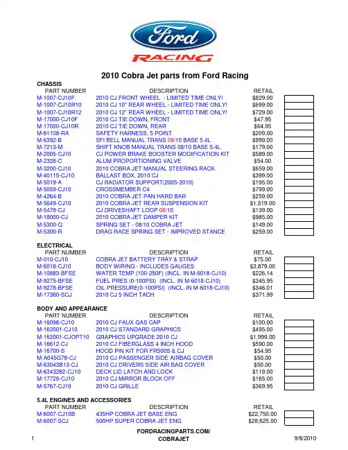
2010 Cobra Jet parts from Ford Racing CHASSISPART NUMBER DESCRIPTION RETAIL M-1007-CJ10F 2010 CJ FRONT WHEEL - LIMITED TIME ONLY!$829.00 M-1007-CJ10R10 2010 CJ 10" REAR WHEEL - LIMITED TIME ONLY!$699.00 M-1007-CJ10R12 2010 CJ 12" REAR WHEEL - LIMITED TIME ONLY!$729.00 M-17000-CJ10F 2010 CJ TIE DOWN, FRONT $47.95 M-17000-CJ10R 2010 CJ TIE DOWN, REAR $64.95 M-61108-RA SAFETY HARNESS, 5 POINT $209.00 M-6392-B SFI BELL MANUAL TRANS 08/10 BASE 5.4L$999.00 M-7213-M SHIFT KNOB MANUAL TRANS 08/10 BASE 5.4L$179.00 M-2005-CJ10 CJ POWER BRAKE BOOSTER MODIFICATION KIT $589.00 M-2328-C ALUM PROPORTIONING VALVE$54.00 M-3200-CJ10 2010 COBRA JET MANUAL STEERING RACK $659.00 M-40115-CJ10 BALLAST BOX, 2010 CJ $399.00 M-5019-A CJ RADIATOR SUPPORT(2005-2010) $195.00 M-5059-CJ10 CROSSMEMBER C4 $799.00 M-4264-B 2010 COBRA JET PAN HARD BAR $259.00 M-5649-CJ10 2010 COBRA JET REAR SUSPENSION KIT $1,519.00 M-5478-CJ CJ DRIVESHAFT LOOP 08/10$139.00 M-18000-CJ 2010 COBRA JET DAMPER KIT $985.00 M-5300-Q SPRING SET - 08/10 COBRA JET$149.00 M-5300-R DRAG RACE SPRING SET - IMPROVED STANCE$259.00 ELECTRICALPART NUMBER DESCRIPTION RETAIL M-010-CJ10 COBRA JET BATTERY TRAY & STRAP $75.00 M-6018-CJ10 BODY WIRING - INCLUDES GAUGES $3,879.00 M-10883-BFSE WATER TEMP (100-250F) (INCL. IN M-6018-CJ10)$226.14 M-9275-BFSE FUEL PRES (0-100PSI) (INCL. IN M-6018-CJ10)$345.95 M-9278-BFSE OIL PRESSURE(0-100PSI) (INCL. IN M-6018-CJ10)$346.01 M-17360-SCJ 2010 CJ 5 INCH TACH $371.99 BODY AND APPEARANCEPART NUMBER DESCRIPTION RETAIL M-16098-CJ10 2010 CJ FAUX GAS CAP $100.00 M-162001-CJ10 2010 CJ STANDARD GRAPHICS $495.00 M-162001-CJOPT10 GRAPHICS UPGRADE 2010 CJ $1,999.00 M-16612-CJ 2010 CJ FIBERGLASS 4 INCH HOOD $590.00 M-16700-S HOOD PIN KIT FOR FR500S & CJ $54.95 M-A045G78-CJ 2010 CJ PASSENGER SIDE AIRBAG COVER $50.00 M-63043B13-CJ 2010 CJ DRIVERS SIDE AIR BAG COVER $50.00 M-6343282-CJ10 DECK LID LATCH AND LOCK $119.00 M-17728-CJ10 2010 CJ MIRROR BLOCK OFF $165.00 M-5767-CJ10 2010 CJ GRILLE $369.95 5.4L ENGINES AND ACCESSORIESPART NUMBER DESCRIPTION RETAIL M-6007-CJ10B 435HP COBRA JET BASE ENG $22,750.00 M-6007-SCJ 500HP SUPER COBRA JET ENG $28,625.00/VISIT WEBSITE FOR DETAILED ENGINE BILL OF MATERIALSM-6316-CJ CRANK DAMPER SFI$779.00 M-9600-SCJ 2010 140MM MAF - 500HP SCJ $635.00 M-9600-CJ 123MM MAF - 435HP ENG $665.95 M-9B659-CJ AIR INLET TUBE 435HP W/TVS$64.99 M-9R504-SCJ AIR INLET TUBE - 500HP SCJ$469.95 M-9Y456-CJ EGR BLOCK OFF PLATE $34.95 M-8080-CJ10 CJ S/C INTERCOOLER KIT $1,500.00 M-6017-CJ10A CONTROLS PACK FOR CJ10 5.4L ENGINES$1,599.00 M-6038-A CJ SOLID MOTOR MOUNT UPRIGHTS KIT $315.00 M-9430-CJ10 5.4L LONG TUBE HEADERS$1,249.00 M-9926-CJ6565MM DUAL BORE THROTTLE BODY - 435HP$689.95 M-9926-CJ65M65MM DUAL BORE MECHANICAL $599.00 M-9926-SCJ OVAL THROTTLE BODY - 500HP TBD M-9926-SCJM OVAL MECHANICAL THROTTLE BODY$679.00 428/352 ENGINESPART NUMBER DESCRIPTION RETAIL M-6007-CJ428COMPLETE COMPETITION READY 428CID ENG CALL M-6007-CJ352COMPLETE COMPETITION READY 352CID ENG CALL VISIT WEBSITE FOR DETAILED ENGINE BILL OF MATERIALSM-9603-CJPR COWL INDUCTION TRAY$999.00 M-9600-CFAC13CARBON FIBER AIR CLEANER$110.95 M-9728-CJ95THROTTLE BRACKET 428$45.00 M-9728-CJ82THROTTLE BRACKET 352$45.00 M-6038-CJPR MOTOR MOUNT KIT$225.00 M-8075-CJ82UPPER RADIATOR PIPE 352$129.95 M-8075-CJ95UPPER RADIATOR PIPE 428$129.95 M-8286-CJPR LOWER RADIATOR PIPE KIT$149.00 M-8500-CJ RADIATOR KIT WITH FAN$1,149.00 M-9424-CJ95INTAKE MANIFOLD 428$660.00 M-9424-CJ82INTAKE MANIFOLD 352$660.00 M-9926-4V175 4 X 1.75" MECHANICAL THROTTLE BODY$699.00 M-6582-LECJ1COBRA JET VALVE COVERS$159.99 M-6049-Z304D CYLINDER HEAD, SOLD INDIVIDUALLY$549.00 M-6010-B302BB ENGINE BLOCK 352$1,759.00 M-6010-BOSS351BB ENGINE BLOCK 428$1,999.00 4.6L 3-VALVE ENGINEPART NUMBER DESCRIPTION RETAIL M-9926-3V DUAL BORE 62MM THROTTLE BODY ELECTRONIC$649.00 M-9926-3VM DUAL BORE 62MM THROTTLE BODY MECHANICAL$599.00 M-9424-463V INTAKE MANIFOLD$599.95 M-6550-3V CAMSHAFT SET$850.00 M-6009-463V 4.6L SHORT BLOCK$1,999.00 M-6067-3V46HEAD GASKET KIT W/HEAD BOLTS$74.95 M-6582-3VB VALVE COVERS BLUE$269.00 M-6582-3VBLK VALVE COVERS BLACK$269.00 M-6050-N3VPA CYLINDER HEAD LH$998.00 M-6049-N3VPA CYLINDER HEAD RH$998.00/M-6017-463V ENGINE INSTALLATION KIT W/ECM AND WIRING $1,350.00M-9430-MC LONG TUBE HEADERS$1,295.00M-6010-A46NA ENGINE BLOCK ALUMINUM BARE$999.00M-6010-BOSS50ENGINE BLOCK IRON BIG BORE BARE $1,199.00M-6010-D46ENGINE BLOCK IRON BARE $619.002008 Cobra Jet PART NUMBER DESCRIPTIONRETAIL M-1007-CJF WHEEL, 2008 CJ FRONT $495.00M-1007-CJR WHEEL, 2008 CJ REAR $585.00M-16098-CJG 2008 CJ GRILLE EMBLEM$84.95M-19216-CJ 5.4L A/C DELETE SVT MUSTANG 10 RIB $162.95M-4602-CJ 2008 CJ DRIVESHAFT$775.95M-6316-CJ FR500CJ SFI CRANK DAMPER $779.95M-5300-Q CJ SPRING KIT$84.95M-8510-M2L FUEL RAIL SPACER KIT $21.99M-9430-CJ 2008 COBRA JET HEADERS $1,199.00M-9603-CJ 2008 CJ CAK$889.00M-9926-CJ2008 CJ THROTTLE BODY(63.5MM) $679.952010 HEADERS 5.4L, 428/352CID WATSON ENGINEERING 14141 5.4L FUEL RAILS17156 ENGINE KIT - RAILS, REGULATOR, FITTINGS, LINES 17157 STEALTH FUEL CELL, TRUNK AND UNDER CAR KIT 17158 COMPLETE FUEL SYSTEM - CELL TO RAIL 18701 FUEL CELL BRACKET428/352 ENGINESHOLBROOK RACING ENGINESMOTORCRAFT #DESCRIPTIONOTC PART #303-D121CRANKSHAFT 3-JAW PULLER303-102CRANKSHAFT DAMPER INSTALLER T74P-6316-B 303-D055STRAP WRENCHD85L-6000-A 303-452 VALVE SPRING COMPRESSOR T93P-6565-AR 303-448CRANKSHAFT HOLDING TOOLT93P-6303-A 303-635CRANKSHAFT FRONT OIL SEAL INSTALLER 303-335OIL SEAL INSTALLERT88T-6701-ALIMITED AVAILABILITY!Contact Distributor for details!Cobra Jet parts from Performance PartnersCobra Jet Special Service Tools 5.4/4.6LPH. PH. 734-762-4315/。

Li f t i n g D ev i c e s2Lifting BeamsEconomicalAdjustable Spreader/Lifting Beam(ASLB16) ............................................. 4 Adjustable Lifting Beam (ALB17) .............. 4 Fixed Spread Lifting Beam (FSLB19) ....... 5 Basket Sling Lifting Beam (BSLB18) ........5 I ndustrialLow Headroom Multiple Spread Lifting Beam (LHLB20) ....................6, 7 Heavy Duty Twin Basket Sling Lifting Beam (HDLB22) ..................................8 Twin Hoist Lifting Beam (THLB25) ...........9 SpreaderFixed Spreader Beam (FSB30) ...............10 Adjustable Spreader Beam (ASB32) .......11 Modular Spreader Beam (MSB14) . (12)Coil LifterD ixon Coil Hook with Pivoting Wedge (DCH80) .....................................13 H eavy Duty Coil Hook (HDCH82) .. (13)Construction ToolsBeam/Girder ClampsBeam Flange Clamp (BFC) (14)Girder Clamp (GC)..................................14 Beam Grab (F) ........................................15 Pipe & Manhole Lifting Pipe Grab (C/S) ......................................16 Pipe Tongs (PLT) ....................................17 Concrete Manhole Lifter (MHL) ..............18 Manhole Sleeve Lifter (MCL) .................19 Tea Cup Pipe Carrier (TC) .....................20 Tea Cup Sling (TCS) ..............................20 Pipe Pick (CPP)......................................21 Barrier Grab (BRG74) . (22)TABLE OF CONTENTSFork Lift AccessoriesBooms F ixed Fork Lift Booms (FFLB) ........................23 S ingle Fork Hook (SFH) .................................23 T elescoping Fork Lift Booms (TFLB) ..............24 D ouble Fork Beam (DFB) ...............................24 P ivoting Fork Lift Booms (PFLB) .. (25)Specialty ProductsFiberglass Battery Lifting Beam (BLB) .............26 Battery Lifting Beam, Low Headroom(BLBLHA) ......................................................27 Adjust-A-Link ....................................................28 Adjust-A-Leg .. (29)Gantry CranesFixed Steel (H90) .......................................30, 31 Adjustable Steel (K90) ................................32, 33Fixed Aluminum (HA90) ...................................34 Adjustable Aluminum (KA90) . (35)3 Quality Engineered ProductsAll of the products in this catalog have beenengineered and produced to the highest qualitystandards and meet or exceed all applicable U.S.government standards including OSHA andASME B30.20 AND B30.9. Random proof testingis standard. Proof testing with certification isavailable upon request for a nominal charge.Product OverviewLifting BeamsPRODUCT INFORMATIONAllow for multiple pick points ofthe load for balance or supportissues. Spreader Beams havea top rigging that add stability tothe lift. Available in 9 standardstyles.Beam/Girder ClampsFor use in lifting and positioningstructural beams. Two stylesmay also be hung from loadbearing beams to suspendhoists or other lifting devices.Coil LiftersUse to lift, manipulate andreposition coils. Requiresminimum aisle space equal toLifter arm length. Available in 2standard styles.Gantry CranesThese portable cranes allow forthe pick up and transport of aload wherever you have asmooth and level floor. Availablein either steel or aluminum, fixedor adjustable height.Pipe & Manhole LiftingFor the lifting and positioningof steel, iron and concrete pipes.Pipe Grabs are for metal pipes.Pipe Picks and Tea Cups forconcrete pipes.Barrier GrabsScissor style grab is the easyway to lift and move concreteroad barriers. Auto-latch forhands-off operation.Forklift AccessoriesThree styles of booms andtwo hook devices provideadded lifting capabilities toyour forklift trucks.Battery Beams provide a non-conductive lifting method forindustrial batteries. (i.e.-forkliftbatteries)Adjust-A-Leg slings allowcontrolled lifting of loads wherelift points are not equidistantfrom the load’s center of gravity.Specialty Products4FEATURES• Use for 2, 3 or 4 point lifting or as spreader beam (add top rigging)• Adjustable lifting points • Good for unbalanced loads • Low headroom • Shackles included • 6" spread adjustments • 4" bail adjustments OPTIONS• Pair of swivel hooks - Code S*• Top chain rigging - Code CFEATURES• Adjust bail for unbalanced load • 6" spread adjustments • Shackles includedOPTIONS• Pair of swivel hooks - Code S*ECONOMICAL LIFTING BEAMSAdjustable Spreader/Lifting Beam (ASLB16)* For Optional Swivel Hooks, add an “S” to part No. Contact Lift-All for added cost.Adjustable Lifting Beam (ALB17)Bail Adjustment forUnbalanced LoadsLift Point Adjustment for Load Length5ECONOMICAL LIFTING BEAMSFEATURES• Fixed spread lifting • Eye hooks with latches• Sealed construction for cleaner beamFixed Spread Lifting Beam (FSLB19)Basket Sling Lifting Beam (BSLB18)FEATURES• Best beam for low headroom applications • Fixed spread lifting• Bent bar hooks allow for 2" wide sling eyes - One set for 3' & 4' spreads - Two sets for 6' - 12' spreads •Spread 2 is 1/2 of Spread 16FEATURES• Great for low headroomapplications• Swivel hooks with latchesstandard•3' & 4' beams have 2 spreads•6' & longer beams have 3 spreads(Inner spread lengths are shorterthan outer spreads by 1' increments•Additional or repositioned holesavailable INDUSTRIAL LIFTING BEAMSLow Headroom Multiple Spread Lifting Beam (LHLB20)7Extra Holes Allows for extra hook positions in addition to the standard holes.Specify number and spread.Low Headroom Multiple Spread Lifting Beam (Continued)Options:Extra HooksAllows for multiple pick points.Saves time from having to move hooks.FasPinsAllows for easy repositioning of hooks.Recommended for frequent hookposition changes.8FEATURES• For use with slings in a basket hitch • Latch hooks designed to minimize sling eye damage• Two sets of fixed hooks are standard for all lengths over 4'• Inner spread is 1/2 of outer spread • Extra spreads available upon requestINDUSTRIAL LIFTING BEAMSHeavy Duty Twin Basket Sling Lifting Beam (HDLB22)9FEATURES• For use with two hoists to increase lift capacity• Swivel hook with latch standardTwin Hoist Lifting Beam (THLB25)INDUSTRIAL LIFTING BEAMSCenter hook offset to accommodate hoists of unequal capacities.Custom pick points for both top and bottom.Center bail and extra pair ofhooks for maximum versatility.10FEATURES• Adds stability to lift where headroom is not limited• Chain rigging standard, wire rope rigging availableFixed Spreader Beam (FSB30)SPREADER BEAMS* Add a "W" for Wire Rope RIggingAdd an "A" for Adjust-A-Link Rigging11SPREADER BEAMSAdjustable Spreader Beam (ASB32)FEATURES• Great versatility and stability where headroom is not limited• Chain rigging standard, wire rope rigging available• Telescoping spread adjusts in 1 in. increments* Add a "W" for Wire Rope RIggingSpread12SPREADER BEAMSModular Spreader Beam (MSB14)FEATURES• Designed to accommodate spreads from 10' to 22'• Capacities in 1 and 2 tons • Lightweight• Faspin with lanyard allows for quick adjustment of spread in 1' increments• Hair pin cotter to rigging attachment • Designed and manufactured to ASME standardsRecommended Optional Top Rigging (Add "R" to Part Number)2 Sets of 2-Leg Tuflex Roundslings per BeamOuter TubeInner Tube - each system contains (2)Short TubeLifting Eye Dimensions13COIL LIFTERSDixon Coil Hook with Pivoting Wedge (DCH80)Heavy Duty Coil Hook (HDCH82)FEATURES• For easy upending of coils from horizontal to vertical• Pivoting wedge great for lifting coils that have been stacked • Wedge also acts as a coil retainer• Excels in use with small, lightweight coils • Good for limited overhead clearance•Standard handle for easier coil positioningFEATURES• Designed for heavy duty applications• High tensile alloy steel plate reduces physical size and weight • Counter balanced to hang level when empty • Inside radius on hooks avoid coil edge contact • Guide handles for ease of hook positioning • Handles a wide range of coil widths•Available with optional padding for additional coil protectionHeadroom14FEATURES• Light weight, portable design• Jaw opening adjusts to a wide range of beam types and flange widths• Built in suspension pin for minimum headroom • Opposing thread screw spindles for rapid operation• Large Bail option available for large crane hooksCONSTRUCTION TOOLSBeam Flange Clamp (BFC)Great for the lifting of or suspension from I-BeamsFEATURES• Heavy duty design for lifting wide range of flange beams and plate girders• Screw-spindle design ensures positive grip • Opposing thread screw spindles for rapid operation• Simple design for minimum maintenanceGirder Clamp (GC)Designed for the lifting of or suspension from large girders and I-BeamsLarge Bail OptionAPBH15FEATURES• Heavy duty design for lifting wide flange beams and plate girders• Recessed base accepts studs in beam surface• Eliminates need for slings, chokers and spreader barsCONSTRUCTION TOOLSBeam Grab (F)(For vertical lifting only, not suspension)Operation:1.Lower grab onto beam.2. Lift arms, if necessary, to slide under beam flange.3. As beam is lifted, pressure forces arms together to secure beam.4. The heavier the beam, the greater the clamping force.W16FEATURES• Automatically clamps to pipe when lowered onto it • Moveable outriggers stabilize the pipe during lift • No blocking required• Quick and efficient handling of properly balanced pipeCONSTRUCTION TOOLSPipe Grab (C OR S)(For cast iron or steel pipe only)Operation:1. Lower grab onto approximate center of pipe. Grab will open and seat on pipe.2. Lift slowly to check for pipe balance. Never exceed a 15° angle.3. If angle exceeds 15°, lower pipe and reposition grab.17FEATURES• Pipe Tongs are made of sturdy construction to handle pipe, round bars, castings, etc• Tongs are provided with bare steel curved gripping arms• Optional replaceable urethane pads available to protect smooth or polished surfaces• Load must be balanced and controlled when lifting • May be used in pairs with a lifting beam for added stabilityCONSTRUCTION TOOLSPipe Tongs (PLT)(For vertical lifting only, not suspension)Decreasing the load by bumping or substantial imbalance can, under certain circumstances loosen the grip.Do not use in diameters other than those specified on nameplate.Specifications - Fixed DiameterSpecifications - Adjustable DiameterFixedAdjustable18FEATURES• Designed for 4"-6" concrete wall thickness• Will not damage concrete seat • Legs can be quickly positioned to balance load• 2 and 3 leg models available • Conforms to ASME B30.9 & B30.20Note: Constant tension required to maintain positive load contact.CONSTRUCTION TOOLSConcrete Manhole Housing Lifter (MHL)2 Leg Model3 Leg Model19TWO LEG LIFTERSTHREE LEG LIFTERSFEATURES• Easy to attach and release from sleeve • The quick and easy way to place cast manhole sleeves• 2 or 3 leg models availableManhole Sleeve Lifter (MCL)Note: Flange diameter range 12"-30".CONSTRUCTION TOOLS20FEATURES• Efficiently handles concrete water and sewer pipes • Three sizes available to lift up to 18 tons • Standard hand grip for ease of installation• Optional spoon handle available to assist Tea Cup placement (Model TC66 only) in small diameter pipesCONSTRUCTION TOOLSTea Cup Pipe Carrier (TC)Tea Cup Sling(TCS)For use with Tea Cup Carriers• 5 ft. standard lengthOPERATION1. Drop TCS Slingdown through hole in pipe2. Align and insert Tea Cup Pipe Carrier onto sling3. Lift pipeModel TC66Tea Cup Spoon Handle (TCSH)(Includes Bolt-on Lip)21FEATURES• Simple and fast• No need to reach inside the pipe• Worker remains above the pipe at all times • Use to easily join length of pipeCONSTRUCTION TOOLSPipe Pick (PP)(For concrete pipe only)Lift arm counter-weighted for easy removal22FEATURES• Labor saving, quick and easy hands-off operation•No slings or chains to attach•Reduces damage to barrier due to moving•Replaceable polyurethane lifting pads for unpaintedbarriers•Replaceable steel "Dog Point" lifting pads for paintedbarriers (typical in coastal areas) CONSTRUCTION TOOLSBarrier Grab (BRG74)The Barrier Grab isdesigned to handle 6"-12"nominal widths at thebarrier top (W)1. Grab in openposition is placedonto barrier. Autolatchwill disengage whenhoist line becomesslack.2. Raising cranehook will thencause pads toengage barrier.3. Lower barrierinto position.4. Slack in hoistline will engageauto-latch, holdinggrab open for removaland placement of nextbarrier.23FEATURES• Easy attachment - no tools required • Welded construction for durability • Promotes versatility of fork lift trucks • 3,000 lb. rated capacityFEATURES• Fixed length beam design• Restraining chain with grab hook FORK LIFT ACCESSORIESFixed Fork Lift Booms (FFLB)Note: Fixed hook shown, swivel hook also available.FFLB-15 Single Pick Point• Use with 1" or 2" wide web sling • Optional swivel hook availableFFLB-40 Multiple Pick Points• 5 alternate hook positions at 1 foot intervals • Fixed or swivel hooks availableSingle Fork Hook (SFH)24FEATURES• Telescoping boom for versatility • T-Pin locks boom into position • Handle on end for easy extension of boom• Swivel hooks with latch are standard• Restraining chain with grab hook standard• 12 ft. maximum horizontal reachFORK LIFT ACCESSORIESTelescoping Fork Lift Booms (TFLB)FEATURES• Easy attachment - no tools required• Welded construction for durability• Promotes versatility of forklift trucksDouble Fork Beams (DFB)Note: Swivel hook shown, fixed hook also available.25FEATURES• Vertical adjustability in 5 increments up to 40°, 6' 4" maximum height• Telescoping boom for versability • T-Pin locks boom into position • Handle on end for easy extension of boom• Swivel hooks with latch are standard• Restraining chain with grab hook standard reachFORK LIFT ACCESSORIESPivoting Fork Lift Booms (PFLB)26FEATURES• Non-conductive for lifting industrial size fork lift or similar batteries• Up to 70% lighter than other beams• Available for single or multiple size batteries• Heavy duty capacities of 4,800 lbs. and 7,000 lbs.• Acid resistant coated polyester straps and hooks • 36" standard spread - custom lengths available • Swivel hooks standardFORK LIFT ACCESSORIESFiberglass Battery Lifting Beam (BLB)Fixed Length (BLBF)Adjustable (BLBA)Optional J HooksAvailable in place of swivel hooksNote: Maximum spread range is 12"* Add a "J" to Part No. for Optional J Hooks27FEATURES• Low Headroom, 18.3"• Adjustable to handle batteries of different lengths • Non-conductive beam• Acid-resistant, coated polyester straps with either swivel or J-hookSPECIALTY BEAMSBattery Lifting Beam (BLBLHA)Low Headroom, AdjustableJ Hooks StandardSwivel Hooks Available28FEATURES• Chain cannot be removed from the master control plate, assuring the capacity rating will not be compromised• Alloy steel master control plate for strength and reliability • Each assembly serialized for traceability• Complies with OSHA - proof tested and certified• Grade 100 chain provides approximately 25% higher capacities than our previous Adjust-A-Links - replaces larger, more expensive slings• New angled plate design reduces bending torque on chain and plate - reduces wear and extends sling life• Wider top bearing surface reduces wear to both plate and crane hook• Versatile - one sling does many jobs• Using two Adjust-A-Links on the same crane hook eliminates the need for expensive triples and quads• Heat treated alloy steel construction for long sling life• Yellow powder coating on master plate and hooks prevents rust – extends sling life• More compact plate design fits larger hooks for easier rigging • Less bulky than typical double adjustable chain slings • High visibility yellow fittings make assembly easy to spot• Easily adjustable to accommodate a wide range of applications • No time wasted searching for just the right slingSPECIALTY SLINGSAdjust-A-LinkThe adjustable, two leg chain slingSingleDoubleBasketNever exceed rated capacities.Chain must be seated at the base of adjusting slot of the Master Control Link.29FEATURES• Easily adjust the legs for a level lift of unbalanced and non-symetrical loads• Can be locked in place for repetitive lifts • Use in pairs for 4 point lifts• Can be used as top rigging for spreader beams • Great as rigging to move machinerySPECIALTY SLINGSAdjust-A-LegThe adjustable, two leg wire rope sling* Reach should be a length of 70% or greater of the distance between pick up points.Level lifting of non-symetrical loads where lift points are not equidistant from center of gravity.Operation:For a level lift, adjust the leg lengths so that the master plate is above the approximate center of gravity. Test position by lifting only until one end of the load is raised. Lower and reposition master plate and legs for another test. Repeat until load raises without tilting. Adjust-A-Leg must be loaded to at least 10% of rated capacity before legs will fully lock into place.Level lifting of symetrical loads where lift points are not equidistant from center of load.Lifting of any load at an angle.Typical Applications30FEATURES• Balanced design allows for easyrolling, even under load•Simple bolt together construction•Includes 4 steel swivel casters• Easy set-up and maintenance GANTRY CRANESFixed Steel (H90)3132FEATURES• Balanced design allows for easy rolling, even under load• Simple bolt together construction • Includes 4 steel swivel casters • Easy set-up and maintenance• Height adjustable in 1 ft. incrementsGANTRY CRANESAdjustable Steel (K90)3334FEATURES•Light-weight Aluminum construction•Balanced design allows for easy rolling,even under load•Simple bolt together construction•Includes 4 poly-coated swivel casters•Easy set-up and maintenance GANTRY CRANESFixed Aluminum (HA90)35FEATURES• Light-weight Aluminum construction • Balanced design allows for easy rolling, even under load• Simple bolt together construction • Includes 4 poly-coated swivel casters • Easy set-up and maintenance• Height adjustable in 6 in. incrementsGANTRY CRANESAdjustable Aluminum (KA90)Manufacturing and Warehousing in:AtlantaChicago Houston Las VegasHeadquarters, Customer Service & Manufacturing:1909 McFarland Dr.Landisville, PA 17538-1810800-909-1964FAX: 717-898-1215E-Mail:*********************CustomerService:****************************Cat. LD-2010 Integra 10M 110LIFTING DEVICES RETURN POLICY1. Items to be returned MUST BE UNUSED and in like new condition.2. An RGA number must be obtained from our Customer Service Agents. No unauthorized returns will be accepted.3. Freight for returns must be prepaid by the customer to the location designated by our Customer Service Agents.4. Requests for returns must be made within 30 days of the original shipment date.5. A 25% restocking charge will apply to all authorized returns.6. Credit will be issued after receipt, inspection and acceptance.7.Custom ordered or modified items may not be returned.。
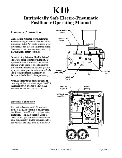
K10Intrinsically Safe Electro-Pneumatic Positioner Operating ManualPneumatic ConnectionSingle Acting Actuator (Spring Return):For single acting actuators Outlet Port 2 is tobe plugged. Outlet Port 1 is to be piped to theactuator inlet port that acts against the spring.(Increasing signal causes pressure to increasein Outlet Port 1 of the positioner).Double Acting Actuator (Double Return):For double acting actuators Outlet Port 2 ispiped to drive the actuator towards the failposition. Outlet Port 1 is piped to drive theactuator away from the fail position. (Increas-ing signal causes pressure to increase in OutletPort 1 of the positioner and pressure todecrease in Outlet Port 2 of the positioner).Note: Air supply to the positioner must beclean, dry, oil free instrument air per ISA-S7.3.Maximum supply pressure is 120 psi. All pneumatic connections are 1/4” NPT. Electrical ConnectionThe electrical connection (4-20 mA Loop Input) to the K10 positioner is polarity sensi-tive. Connect the 4-20 mA Loop Input to ter-minal block J1 on the Connector Board as shown on the right (Positive lead to terminal point 3 and negative lead to terminal point 2). The wire size can range from 20 to 14 AWG.ConduitOpening4-20 mAInput (+)4-20 mAInput (-)Position Sensor Initial Angle (Setting Mode)The K10’s Position Sensor, which measures the absolute position of the valve, has a limited operating angle for proper position measurement. The Position Sensor must remain within the operating angle in both the open and fail valve positions. This is accomplished by initially setting the Position Sensor angle while the valve is in the fail position. The K10 has a mode of operation to accomplish the setting of this initial angle using the following steps.1. Apply loop current to the positioner and adjust to12 mA.2.Press & hold both the high and low buttons untilthe actuator is driven to span position. Release both buttons to remove air pressure from Outlet Port 1.3. If the valve fails clockwise and strokes counter-clockwise, then set switch SW1 to the CCW position. If the valve fails counter-clockwise and strokes clockwise, then set switch SW1 to the CW position (see figure to right).4.With no buttons pressed and the actuator in thefail position, push the Main Shaft Gear (larger of the two) down until it disengages from its shaft locking position.5.Rotate the Main Shaft Gear (both gears willturn), until only the green LED is flashing.Note: If the LED is already green, skip 5 and go to 6.6.Pull up the Main Shaft Gear allowing it to re-engage on the shaft locking it into position.7.Press and hold the High Calibration button untilthe valve fully strokes away from the fail position while watching the LED’s. The red or yellow LED’s must not light as long as the High Cal but-ton is being held down. If the red or yellow LED lights while the High Cal button is being held down, then the Position Sensor Orientation and Actuator air piping are out of phase. Correct the phase error by changing the position of SW1 and repeat this procedure starting from step 2.8.Release the High Calibration button and watch the red LED. The red LED will flash until the valve reaches the fail posi-tion.9.Press the Low Calibration button to exit the Position Sensor Setting Mode (if no buttons are pushed then this mode willtime out automatically in about 2 minutes).Main Shaft GearPosition SensorGearSwitch (SW1)CCWCWCalibrating The K10 PositionerOnce the K10 and actuator have been connected and the initial angle has been set. Low and High Calibration can be performed on the K10. Low Calibration refers to the input current value that drives the valve into the fail position. High Calibration refers to the input current value that drives the valve into the Span Position. Calibration adjusts parameters internal to the K10 that are specific to the actuator, and input current values. The parameters that are adjusted are, the Gain of the K10 servo loop. the end position (Zero/Span) of the valve travel, and Drop-Off point (input current level at which the transducer is forced to the extreme position, to insure that the valve is fully open or closed). The calibration routine uses the input current value to set it’s internal adjustment, so it is important that the input current does not change during the calibration routine.To Do a Low Calibration: (Zero Position)1.Set the Input Current level to the value that drives the valve into the fail position (typically 4 mA).2.Start the Low Calibration routine by pressing and holding the LOW CAL button on the K10 until the Yel-low LED flashes.3.Observe the flashing Yellow LED on the K10 which denotes the various stages of the calibration routine:a.) Flashing 1 time indicates Zero position set routine.b.) Flashing 2 times indicates Transducer Self Calibration routine.c.) Flashing 3 times indicates Gain setting routine.4.When the Green LED begins to flash the Calibration is completed. If the Red LED flashes this is an indica-tion that one of the Calibration routines could not be completed. The number of Red LED flashes indicates the calibration routine that failed.To Do a High Calibration: (Span Position)1.Set the Input Current level to the value that drives the valve into the span position (typically 20 mA).2.Start the High Calibration routine by pressing and holding the HIGH CAL button on the K10 until the Yel-low LED flashes.3.Observe the flashing Yellow LED on the K10 which denotes the various stages of the calibration routine:a.) Flashing 1 time indicates Span position set routine.b.) Flashing 2 times indicates Transducer Self Calibration routine.c.) Flashing 3 times indicates Gain setting routine.4.When the Green LED begins to flash the Calibration is completed. If the Red LED flashes this isan indication that one of the Calibration routines could not be completed. The number of Red LED flashes indicates the calibration routine that failed.Calibration Complete:******Note: For split range enter desired input values during low & high calibration.Advanced FunctionsThe K10 has the ability to change the calibration settings (Gain, Zero, Span, and Drop-Off) manually. This function was intended to make minor changes in the calibration values after doing the Low and High calibration. Some examples where this might be used are decreasing the Gain if the valve still shows some overshoot on rapid position changes, or increasing the High Drop-Off point so it will not be in effect at 20mA. Exercise caution if using the manual calibration, mis-adjustment of these settings on the K10 positioner can result in erratic behav-ior or failure of operation, and may require resetting the EEPROM before auto-calibration can be performed again.To Do a Manual Calibration Adjustment:Before performing a Manual Calibration Adjustment the positioner needs to be calibrated as described previ-ously.1.Apply Input Current to the K10.2.Start the Manual Calibration routine by pressing and holding the Function (center) button on the K10 untilthe Green and Yellow LED flashes.3.Observe the flashing Green and Yellow LED on the K10 which denotes the various stages of the manualcalibration routine, pressing the Function (center) button again advances to the next stage:a.) Flashing 2 time indicates Manual Gain adjustment.b.) Flashing 3 times indicates Low Drop-Off adjustment.c.) Flashing 4 times indicates Zero position adjustment.d.) Flashing 5 times indicates High Drop-Off adjustment.e.) Flashing 6 times indicates Span position adjustment.4. To alter any characteristics of the positioner follow the following steps:a.) Manual gain Increase the positioner gain by pressing and holding the High Cal button. Decrease thePositioner gain by pressing and holding the Low Cal button. The maximum adjust-ment has been achieved when the red LED lights.b.) Low Drop-Off Increase the mA input signal that the positioner drops output port 1 pressure by press-ing the High Cal button. Decrease the mA input signal that the positioner drops outputport 1 pressure by pressing the Low Cal button.c.) Zero position[To adjust the zero position to a point other than the hard stop of the valve the Lowcalibration of the positioner must have been performed at a current slightly lower thanthe zero position current. (Ex. If the zero position current is 4.0 mA the Low Calibra-tion as described in the previous section needs to be performed at 3.9 mA.)]Increase the zero position by pressing and holding the High Cal button. Decrease thezero position by pressing and holding the Low Cal button. Continue to increase ordecrease the zero position by repeatedly pressing and holding the buttons.d.) High Drop-off Decrease the mA input signal that the positioner drops output port 2 pressure bypressing and holding the Low Cal button. Increase the mA Input signal that the posi-tioner drops output port 2 pressure by pressing the High Cal button.e.) Span Position [To adjust the span position to a point other than the hard stop of the valve the Highcalibration of the positioner must have been performed at a current slightly higherthan the span position current. (Ex. If the span position current is 20.0 mA the Highcalibration as described in the previous section needs to be performed at 20.1 mA.)]Decrease the span position by pressing and holding the Low Cal button. Increase thespan position by pressing the High Cal button.5. The Input Current can be changed during the test to observe the adjustment effects on the K10 behavior.6. To save the adjustments and exit the Manual Calibration Mode the Function (center) button must be heldfor approximately 5 seconds (green and yellow flashing LED’s will change to flash just green when adjust-ments are saved) This procedure to save and exit can be performed from any stage during the Manual Cal-ibration.7. Pressing the Function (Center) button during the High Drop-Off adjustment exits the Manual CalibrationMode without saving any adjustments made.Dip SwitchesDip switch #1Off Position (Factory Setting) = Normal Acting (4 mA represents zero/Fail position and 20 mA repre-sents Span position).On Position = Reverse Acting (20 mA represents zero/Fail position and 4 mA represents Span posi-tion).Dip switch #2: NOT USED. Unit will operate with switch in either position.Dip Switch#1Dip Switch#2Dip Switches shown in factory set positionsCCWCWResetting the EEPROM Back to FactoryDefault ValuesThe positioner has an internal Electrically Erasable Programmable Read Only Memory (EEPROM)that is used to store the calibration values. These values remain in the EEPROM memory even if power is removed from the positioner. During normal operation of the positioner the EEPROM will not have to be reset. The memory may become corrupted if power to the positioner is lost while the positioner is writing to the EEPROM. which only happens at the very end of the calibration cycle or at the end of the Position Sensor Initial Angle setup. This memory can be reset back to factory default values by holding down the HIgh Cal button while the positioner is being powered up. After the EEPROM is reset, the positioner will have to be calibrated again.Reversing the 4mA and 20mA Positions (Reverse Acting)Normally 4mA of input current represents the closed valve position and 20mA represents the open valve position. The positioner has the option to switch this so 20mA represents the closed valve position and 4mA represents the open valve position. The normal mode is chosen by setting the positioner DIP Switch position 1 (the one closest to the LED’s) to the “OFF” position (toward the LED’s). The reverse acting mode is chosen by setting the positioner DIP switch position 1 to the “ON” position (away from the LED’s). The positioner should be calibrated again any time the switch position is changed.Setting the Switches1.Operate the actuator to one extreme. Choose the switch you would like to signal this position (upperor lower switch). Disengage the appropriate switch cam from the spline by pushing or pulling against the spring (push down for the upper switch, lift up for the lower switch).2.Turn the cam until the switch is activated. Activation of the switch can be monitored using a continuitytester or equivalent means.3. Release the cam allowing it to re-engage with the spline.4. Operate the actuator to the opposite extreme and repeat steps 1 through 3 for the other switch.Wiring SchematicTOP CAMPUSH DOWNTURN & RELEASEBOTTOM CAMLIFT UPTURN & RELEASETOP CAMPUSH DOWNTURN & RELEASESWITCH#1UPPERNCNOCBROWNPURPLEYELLOW123456REDBLUEORANGECNONCSWITCH#2LOWERGNDParts List1OptionalMechanical SwitchAssembly8*Item #Description1Housing Ass’y Qty 23456111111Shaft Ass’y Electronic Ass’y Transmitter (optional)Manifold Ass’y Motor Ass’y71Connector Board Ass’y81Mechanical Switch Ass’y (optional)*Void FM approval as Non-Incendive when ordered with 2-SPDT switch option .K10 product with optional switches is for use in general purpose applications only.6735241Technical DataInput Current 4 to 20 mA (Analog)Voltage Drop 9 voltsSupply Air Pressure (low) Resolution 0.5% of span Linearity ±1% of spanConduit 1 x 3/4” NPTEntriesHousing Engineered Resin (Nylon)Cover Clear Engineered Resin (Nylon)Shaft Stainless Steel Fasteners Stainless Steel HiVue Copolyester Electrical Version SPDT form CElectrical Rating15 Amps @ 125/250 VAC 10 Amps @ 24 VDC 0.5 Amps @ 125 VDC 0.25 Amps @ 250 VDC(high) 15 to 45 psi40 to 120 psi Hysteresis 0.4% of span Repeatability 0.4% of span Thermal Coefficient 3%/100°COutput Flow Rates 8.0 scfm @ 25 psi (226.5 liter/min) 16.2 scfm @ 90 psi (458.7 liter/min) Air Consumption .003 scfm @ 25 psi (.08 liter/min) .008 scfm @ 90 psi (.23 liter/min) Operating Temp. Range -40°C to 85°C (-40°F to 185°F) GainElectrically Adjustable Air Connection Ports1/4” NPTModMountEngineered Resin (Nylon)Manifold Anodized Aluminum F MAPPROVEDNon-IncendiveClass I, Div 2 Grps A,B,C,D Class II, Div 2 Grps F ,G Class III, Div 2*Void FM approval as Non-Incendive when ordered with 2-SPDT switch option .K10 product with optional switches is for use in general purpose applications only.***DimensionsAppendix AElectro-Pneumatic Positioner Transmitter Calibration Procedure1.Calibrate the Positioner per the operating manual provided with the product.2. Stroke the valve to the fully clockwise extreme.3.Depress the main shaft gear disengaging it from its locking position, take extreme care Not to Turn the main shaftgear, as this will take the positioner out of calibration.4.With the main shaft gear depressed turn the transmitter gear to the fully counter clockwise position, and note thereading (mA) of the transmitter. Next, turn the transmitter gear clockwise until the transmitter changes no more then 0.5 mA from previous reading.5.Turn the clockwise mA adjustment screw to adjust the transmitter reading to the desired output for this valve posi-tion (typically this is 4 mA or 20 mA).6.Stroke the valve to the fully counter clockwise extreme.7.Turn the counter clockwise mA adjustment screw to adjust the transmitter reading to the desired output for thisvalve position. 8.Stroke the valve between the full clockwise and counter-clockwise positions checking and readjusting the (mA) out-put as necessary.Main ShaftMain Shaft Gear mA Adjustment Screw Transmitter GearmA Adjustment Transmitter {OutputTerminals 1 & 2(Not Polarity Dependent)for clockwise positionScrew for counter-clockwise positionCWCCWCCWCW。

电动执行器使用说明书日照德艺智能仪表有限公司RIZHAODEYIZIDONGKONGZHISHEBEICHANG电话:************传真:************一、产品用途一体化智能电动执行机构采用先进的智能数字控制技术,无需另外配置反馈单元和伺服放大器,可直接接收工业控制仪表或计算机输出的4~20mA DC信号。
可对各种工业球阀、碟阀、风门、挡板、偶合器等实现准确位置控制。
该产品不仅提高了电动执行机构位置控制的精度,而且实现了小型化、智能化、一体化(控制器与执行机构合为一体)。
与传统的电动执行机构相比,具有体积小、重量轻、精度高、功能强、性能可靠、运转成本低、不需要维护保养等特点,可广泛应用于电站、石油、化工、冶金、医药、轻工等行业。
二、型号规格备注:S: 触点信号输出型R:角度信号输出型M:普通型Z:智能型三、主要技术参数电源:交流220V±10%,50Hz/60Hz控制精度:0.3%~3.0%可调输入信号:4~20mA DC或1~5V DC输入阻抗:200Ω位置反馈信号:光电隔离输出4~20mA DC位置反馈电阻:500Ω~1KΩ定位方式选择:手动/自动作用方式选择:正作用/反作用自动定位标定:全开/全闭开关输出容量:交流600V,10A安全位置选择:输入信号故障时电动执行机构所处位置可选为全开/停止/全闭保护功能:内置过热保护器,同时具有软件、电气和机械三重限位保护防护性能:相当于IP67回差:≤1%使用环境温度:-10℃~+70℃相对温度:≤85%阻尼特性:≤半周期安装方向:360°全方位四、工作原理与结构将来自控制单元的输入信号(4~20mA DC/1~5V DC)和来自电位器的位置反馈信号进行比较,按消除偏差的方向驱动马达,在输入信号的设定位置停止。
驱动电机的转动通过直齿柱齿轮传动到蜗杆和蜗轮。
电机按正或反方向转动时,输出轴按顺时针或逆时针方向转动。

1235467710111211Use extreme caution when using any device or feature that may take your attention off the road. Your primaryresponsibility is the safe operation of the vehicle. Use only non-essential features and devices when it is safe to do so.89The system illustrated here is the navigation based audio system. Please refer to your navigation supplement for complete information on this system.1 H eadlampsT urns the headlamps off. T urns on parking, instrument panel, license plate and tail lamps.T urns on headlamps. (if equipped) Automatically turns the exterior lamps on/off based on available daylight.(if equipped) T urns on fog lamps by pulling the control towards you.2 p anel d immer C ontrolPress \ to adjustthe instrument panelbrightness. Press and hold to turn on the interior courtesy lights. Press to turn off.3 i nterior t runk r elease4 m ulti -F unCtion l everRotate the end of the control up/down to increase/decrease the speed of the wipers. Push the end of the stalk: • q uickly for a single swipe without fluid • a nd hold briefly forthree swipes with washer fluid • a nd hold for a longerwash cycle.Note: For optimal wiper performance, clean blades and glass regularly . Refer to your Owner’s Guide for more information.5 t ilt /t elesCope s teering W Heel6 m essage C enterDisplays important vehicle information through a constant monitoring of vehicle systems. The system will notify you of potential problems with a display of warnings followed by a longindicator chime. Use the INFO, SETUP and RESET buttons to access variousmenus and settings within the message center. Refer to your Owner’s Guide for more information.7 s teering W Heel C ontrolsTo set the speed: 1. Press ON. 2. A ccelerate to the desired speed. • P ress SET + and takeyour foot off the accelerator. • T o set a higher speed,press and hold SET + or press SET + repeatedly until the desired speed is reached. • T o set a lower speed,press and hold SET – or press SET – repeatedly until the desired speed is reached. • T o return to apreviously set speed, press RESUME. • T o turn off, depress thebrake pedal or press OFF .VOL +/-: Press to increase/decrease volume levels.: Press to access the previous/next radiostation, CD track or preset satellite radio channel.M EDIA: Press repeatedly to access all possible media sources.: Press to access voice recognition, if equipped.: Press to access SYNC ® phone features, if equipped.8 H azard F lasHer9 p assenger a irbag o Illuminates when the passenger airbag has been turned off due to the system sensing light to medium weight in the front passenger seat. For complete information, refer to the FrontPassenger Sensing System in the Seating and Safety Restraints chapter of your Owner’s Guide.10 n avigation s ystem (iF equipped )The Mobile Media Navigation System allows you to record CDs, listen to your saved music, play DVDs and access climate control options in addition to navigating the vehicle. Refer to your Navigation supplement for more information.TracTion conTrol tmIlluminates when Advance-ractionControl TM is active. If the light remains on, contact your authorized dealer as soon as possible.Service engine SoonIlluminates briefly whenthe ignition is turned on. Ifit remains on or is blinking after the engine is started, the On Board Diagnostics System (OBD-II) has detected a malfunction. Drive in a moderate fashion and contact your authorized dealer as airBag readineSSIlluminates briefly when the ignition is turned on. Ifthis light fails to illuminate, remains on or continues to will also sound if there is a malfunction in the indicator light.aBS (anTi-lock Brake SySTem)Illuminates briefly when the ignition is turned on. If the light remains on or continues to flash, a malfunction has been detected. Contact your authorized dealer as soon as possible and have the system serviced. Normal braking (less ABS) is still functional unless the brake warning light is also illuminated.low Tire PreSSure warningIlluminates when your tire pressure is low . If the light remains on, the tire pressure should be checked. If the light does not turn on or begins to flash when the ignition is first turned on or while driving, contact your authorized dealer as soon as possible.ThroTTle conTrol/ TranSmiSSionIlluminates when apowertrain or AWD fault is detected. If the light remains on, or continues to come on, contact your authorized dealer for service as soon as possible.v ol Push to turn the system on/off. T In-dash CD6/MP3 satellite compatible sound system (if equipped)2010QUICK REFERENCE GUIDEfusionAdditionAl feAturesDual automatic temperature control (if equipped)FusionJanuary 2009 First PrintingQuick Reference GuideAE5J 19G217 AAfusionThe system illustrated here is the navigation based climate system.Please refer to your Owner’s Guide for complete information on this system.This Quick Reference Guide is not intended to replace your vehicle Owner’s Guide which contains more detailed information concerning the features of your vehicle, as well as important safety warnings designed to help reduce the risk of injury to you and your passengers. Please read your entire Owner’s Guide carefully as you begin learning about your new vehicle and refer to the appropriate sections when questions arise.All information contained in this Quick Reference Guide was accurate at the time of duplication. We reserve the right to change features, operation and/or functionality of any vehicle specification at any time. Your Ford dealer is the best source for the most current information. For detailed operating and safety information, please consult your Owner’s Guide.Ford Motor CoMpANyCustomer relationship Center | p .o. Box 6248 | dearborn, MI 481211-800-392-3673 (Ford) | (tdd for the hearing impaired: 1-800-232-5952)Press to turn on/off.auTo/driver Side TemPPress to activate automatic temperature control. The system will automatically determine fan speed, air-flow location, A/C (on or off) and outside or recirculated air, to heat or cool the vehicle to reach the desired temperature. Press again to deactivate. T urn to increase/decrease the temperature on the driver side of the vehicle (when PASS TEMP is active) or for the entire vehicle cabin (when PASS TEMP is not active).PaSSenger TemPPress to activate the passenger side climate control (Dual Zone). T urn the control to increase/decrease temperature on the passenger side. Press again to turn off and return to Single Zone where the driver side temperature control determines the temperature for the entire vehicle.maX a/CDistributes recirculated air through the instrument panel vents to cool the vehicle. This mode is more economical and efficient. May also help reduce undesirable odors from entering the vehicle.Fan SPeedPress + to increase or – to decrease fan speed.Distributes outside air through the windshield defroster and demister vents. Can be used toclear thin ice or fog from the windshield.Recirculated air may reduce the amount of time needed to cool down the interior of the vehicle and may also help reduce unde-sirable odors from reaching the interior of the vehicle. Press to activate and clear the rear window and side heated mirrors (if equipped) of thin ice and fog. Press again to deactivate.airFlow modeSSelect if you would like airflow through the panel vents , floor vents , panel and floor vents , or through the defrost/ floor vents .r earvieW C amera (iF equipped )This system provides a visual display of the area behind the vehicle. The display automatically appears on the navigation screen (if equipped) or in the rear view mirror when the vehicle is in Reverse (R) and uses colors (green, yellow and red) to alert you of your proximity to objects. Note: Visibility aids do notreplace the need to watch where the vehicle is moving. Refer to your Owner’s Guide for safety information, more detail, and limitations.synC ® (iF equipped )SYNC ® is a hands-free communications and entertainment system with special phone and media features. For more information, please refer to the SYNC ® Supplement, the SYNC ® section in the Navigation Supplement(if equipped) or visit www .b lind s pot i nFormation s ystem ® (blis ®) WitH C ross t raFFiC a lert (Cta) (iF equipped )BLIS ® uses radar sensors to help you determine if a vehicle may be in your blind spot zone when driving on roads andfreeways. The CTA feature alerts you if a car is coming toward you when you are backing out of a parking space. Note: Visibility aids do not replace the need to watch where the vehicle ismoving. Refer to your Owner’s Guide for safety information, more detail, and limitations.i ntegrated k eyHead t ransmitter (ikt)•P ress once to lock all doors. Press again to confirm all doors are closed.• P ress once to unlock the driver’s door. Press again within five seconds to unlock all doors.• P ress to activatethe panic alarm. Press again or turn the ignition on to deactivate.• P ress twice within three seconds to open the trunk.• C ar finder: Press twice within three seconds to locate your vehicle. The horn will chirp and the turn lamps will flash.r everse s ensing s ystem (iF equipped The reverse sensing system may warn you if there is an object behind the vehicle. A warning tone will sound which increases in frequency as the object gets closer and then will sound continuously when the object is less than 10 inches away . The system is active when the vehicle is in Reverse (R) and traveling less than 3 mph (5 km/h). Note: Visibility aids do not replace the need to watch where the vehicle is moving. Refer to your Owner’information, more detail, and limitations.of airbags or the activation of the safety belt pretensioners. The turn signals will flash and the horn will sound. To deactivate, press the hazard flasher control, or on o close from a venting position: Press and。
![[中文版]DXK-2010(配料秤)(1)](https://uimg.taocdn.com/fbc4f1377375a417876f8f09.webp)
Switching Between Image SourcesPress the Search button or one of the source buttons (remote control), or the Source Search button (projector).Selecting the Lens TypeMake sure the Lens Type setting is correct for the lens you are using.1. P ress the Menu button.2. S elect Extended > Operation >Advanced > Lens Type .N ote: If the Lens Type setting is greyed out, the projector has automatically detected the installed lens and you can skip the remaining steps.3. S elect the lens you are using.4. W hen you’re done, press the Menubutton to exit.Changing Screen TypeSet the Screen Type setting to the screen’s aspect ratio. 1. P ress the Menu button.2. S elect Extended > Display >Screen > Screen Type .3. S elect the screen’s aspect ratio.N ote: The displayed image should matchthe screen’s size and aspect ratio.Turning the Projector On1. T urn on your computer or imagesource.2. R emove the lens cover.3. P ress the On button on theprojector or the remote control. After the status light stays blue, the projector is ready.N ote: If the Direct Power On function is enabled, you can turn the projector on without pressing the On button; just plug it in or flip the switch controlling the outlet to which the projector is connected. To turn on this feature, see the online User’s Guide .4. I f your image does not appear, see“Switching Between Image Sources” or “Troubleshooting.”Changing the Language of the Projector MenusThe default language of the projector’s menu system is English, but you can change it as necessary.1. P ress the Menu button to accessthe projector’s menu system.2. S elect Extended > Language .3. S elect your language.4. W hen you’re done, press the Menubutton to exit.2. P ress the or arrow buttons tomake the adjustment. 3. P ress the Esc button to finish theadjustment.Correcting Image ShapeIf your image is uneven on the sides, you can use the projector’s distortion correction features, such asH/V-Keystone and Quick Corner ®, to adjust the shape. See the online User’s Guide .Making Other Image AdjustmentsFor help on using the projector’sfeatures to improve the image quality, see the online User’s Guide . You can also view information on how to adjust the image color, position, and edges (Edge Blending) when projecting from multiple projectors to create one seamless widescreen image.Turning the Projector OffPress the Standby button to turn the projector off. If you see a confirmation message, press the Standby button again.Note: If the Direct Power On function isenabled, you can unplug the projector or flip the switch controlling the outlet to which the projector is connected instead. To turn on this feature, see the online User’s Guide .With Epson’s Instant Off ® technology, you don’t have to wait for the projector to cool down; just turn it off or unplug it when you’re done.4. W hen you’re done, press the Menubutton to exit.N ote: After changing the screen type, you may need to change the aspect ratio of the projected image depending on the inputsignal. Press the Aspectbutton on the remote control to change the aspect ratio, if necessary.Adjusting Image Position1. P ress the Lens Shift button(remote control) or the Lens button (projector).2. P ress the arrow buttons to adjustthe position of the projected image.3. W hen you’re done, press the Escbutton to finish the adjustment.If the projector is on a table, you can level the image by turning any of the projector’s adjustable feet.Zooming and Focusing1. O n the remote control, press theZoom or Focus button.O n the projector, press the Lensbutton repeatedly until the focus or zoom adjustment screen is shown.TroubleshootingIf you see a blank screen or the message No signal•M ake sure the status light on the projector is blue and not flashing, and the lens cover is removed.•M ake sure the cables are connected correctly. See the online User’s Guide.•Y ou may need to change the image source. See “Switching Between Image Sources.” Also make sure the source device is turned on.If the projector and the notebook don’t display the same image Windows®If you are using a Windows laptop, press the function key on your keyboard that lets you display on an external monitor. It may be labeled CRT/LCD or have an icon such as . You may have to hold down the Fn key while pressing it (such as Fn + F7). Wait a moment for the display to appear.On Windows 7 or later, hold down the Windows key and press P at the same time, then click Duplicate.MacOpen System Preferences and select Displays. Click the Arrangementtab and select the Mirror Displays checkbox.Where to Get Help ManualsFor more information about using the projector, you can view or download the online manuals from the Epson website, as described below.Internet supportVisit /support (U.S.) or www.epson.ca/support (Canada) and search for your product to download software and utilities, view manuals, get FAQs and troubleshooting advice, or contact Epson.Speak to a support representativeTo use the Epson® PrivateLine® Support service, call (800) 637-7661. This service is available for the duration of your warranty period. You may also speak with a projector support specialist by dialing (562) 276-4394 (U.S.) or (905) 709-3839 (Canada).Support hours are 6 amto 8 pm, Pacific Time, Monday through Friday and 7 am to 4 pm, Pacific Time, Saturday. Days and hours of support are subject to change without notice. Toll or long distance charges may apply. Purchase supplies and accessories You can purchase an air filter(V13H134A46), screens, or other accessories from an Epson authorized reseller. To find the nearest reseller, call 800-GO-EPSON (800-463-7766). Or you can purchase online at (U.S. sales) or www.epsonstore.ca (Canadian sales). For a list of optional accessories, see the online User’s Guide.Turn the projector on Illuminate buttons temporarily Automatically adjustcomputer image Change the aspect ratio Open menus assigned by userZoom in or out on part of an imageCorrect image distortion Save and apply presetsPort to connect remotecontrol cableControl one or multiple projectorsDisplay the projector ID andremote ID Use to enter numbers Select color modes Turn the projector offSelect a source Navigate through menu settingsDisplay a test pattern Adjust the image position Open projector menusSelect menu settings Temporarily turn off display and audioMove to next or previous image when projecting from a computer over the networkControl volumeCancel current operation or return to previous menu Display the Info menuSwitch image sourcesFreeze the image Split the screen between two inputs Adjust the focusChange the image sizeReset menu settings to their default valueDisplay the Home screenRemote Control MapEPSON, Instant Off, and Quick Corner are registered trademarks and EPSON Exceed Your Vision is a registered logomark of Seiko Epson Corporation.PrivateLine is a registered trademark of Epson America, Inc.Windows is a registered trademark of Microsoft Corporation in the United States and/or other countries.Mac is a trademark of Apple Inc., registered in the U.S. and other countries.HDBaseT is a trademark of the HDBaseT Alliance.General Notice: Other product names used herein are for identification purposes only and may be trademarks of their respective owners. Epson disclaims any and all rights in those marks. This information is subject to change without notice.© 2021 Epson America, Inc., 4/21CPD-60571。
电动执行器使用说明书日照德艺智能仪表有限公司RIZHAODEYIZIDONGKONGZHISHEBEICHANG电话:0633- 传真:0633-一、产品用途一体化智能电动执行机构采用先进的智能数字控制技术,无需另外配置反馈单元和伺服放大器,可直接接收工业控制仪表或计算机输出的4~20mA DC信号。
可对各种工业球阀、碟阀、风门、挡板、偶合器等实现准确位置控制。
该产品不仅提高了电动执行机构位置控制的精度,而且实现了小型化、智能化、一体化(控制器与执行机构合为一体)。
与传统的电动执行机构相比,具有体积小、重量轻、精度高、功能强、性能可靠、运转成本低、不需要维护保养等特点,可广泛应用于电站、石油、化工、冶金、医药、轻工等行业。
二、型号规格备注:S: 触点信号输出型R:角度信号输出型M:普通型Z:智能型三、主要技术参数电源:交流220V±10%,50Hz/60Hz控制精度:0.3%~3.0%可调输入信号:4~20mA DC或1~5V DC输入阻抗:200Ω位置反馈信号:光电隔离输出4~20mA DC位置反馈电阻:500Ω~1KΩ定位方式选择:手动/自动作用方式选择:正作用/反作用自动定位标定:全开/全闭开关输出容量:交流600V,10A安全位置选择:输入信号故障时电动执行机构所处位置可选为全开/停止/全闭保护功能:内置过热保护器,同时具有软件、电气和机械三重限位保护防护性能:相当于IP67回差:≤1%使用环境温度:-10℃~+70℃相对温度:≤85%阻尼特性:≤半周期安装方向:360°全方位四、工作原理与结构将来自控制单元的输入信号(4~20mA DC/1~5V DC)和来自电位器的位置反馈信号进行比较,按消除偏差的方向驱动马达,在输入信号的设定位置停止。
驱动电机的转动通过直齿柱齿轮传动到蜗杆和蜗轮。
电机按正或反方向转动时,输出轴按顺时针或逆时针方向转动。
输出轴的运动通过齿轮传到带有间隙补偿功能的电位器,开度位置得到检测并反馈到控制单元。
T h e D E B O S t e p ®Installation Instructions for DEBO Step ® Model 20100Fits: 1) 94-02 Dodge (except 02 1500), With Factory Hitch or Equivalent. 2) Most makes & models of full size pick ups, with after market hitches, with 2 ½” Squ are, Straight Across Crossbar.DEBO Step ®Installed, Stowed PositionShown mounted on right side, can mount on left. DEBO Step ®Extended for use with tailgate down.(Latch knob is now black, yellow shown) Tools required for Installation: Wrenches or sockets , ¾”, 2 required.Parts List: (1) DEBO Step ®, (1) Hex bolt ½ x 3 ¾”, (1) ½" Nylock Hex Nut (1) Instruction SheetFOR YOUR SAFETY! The mounting bracket slide is wire tied to the step bar. DO NOT Remove until your step is mounted to the vehicle. If unlatched, the bracket is free tomove, and could cause injury. SEE Step 4.Step 1. The DEBO Step ® mounts on the hitch frame cross bar. The position on the crossbar depends on the truck and the hitch details.Remove the bolt from The DEBO Step ® u-bracket.Position The DEBO Step ® where it will clear the electrical connections, exhaust pipe, etc. Typically, there is clearance under the spare tire, so the step can be mounted anywhere along the crossbar.(Note: to drop the spare, extend the step)Slide the u-bracket on your step up over the crossbar of your hitch frame as shown at left.Step 2. Installthe hex bolt inthe cross holesof the u-bracket,as shown at left.The bolt can beinstalled in eitherdirection.Step 3. Installthe nylock hexnut and tightensecurely! Torqueto 45-50 ft-lbs.Step 4. Removethe wire tie.Your DEBOStep® is readyfor use.NOTE: Your DEBO Step® will be at a slight angle downward when fully extended, due to the clearance between the step bar and the slide guide end plates. This design feature is what makes The DEBO Step® self locating!Use your DEBO Step®in any position. The step bar rotates slightly until it contacts the slide bracket at the points of contact. These “contact pressure points” resulting from the slight angle are what keeps the step from sliding when in use in any position. Remember this feature when operating your DEBO Step®.TO OPERATE: Using one hand, at the same time, lift the latch knob “up” with the fingers to unlatch an d hold, push “down” lightly with the thumb on the step pad to align the step bar with the slide bracket, and “pull” out to any desired position. Pull out part way for use with the tailgate up. Pull out to the fully extended position for use with the tailgate down. To store, simply slide the step in. No need to touch the latch knob. Just push in until the latch engages, as simple as closing a door! Remember, the secret to moving the step bar freely is to release the “contact pressure points” by aligning the step bar with the slide bracket.It’s really quite easy. After just a couple of trie s, you will find:It’s as simple as closing a door!DO NOT EXCEED! Weight limit 400 pounds.For Best Results Use Frequently!THANK YOU for using our product. Tell your friends to get one too!The DEBO Step® team.For help or comments call the 24/7 Hotline: (608) 577-4003 Made in USA by: DoMore Truck Company, 120 N Grand Ave, Hartford, WI 53027。
电动执行器使用说明书日照德艺智能仪表RIZHAODEYIZIDONGKONGZHISHEBEICHANG:0633-8582088 :0633-8583926一、产品用途一体化智能电动执行机构采用先进的智能数字控制技术,无需另外配置反馈单元和伺服放大器,可直接接收工业控制仪表或电脑输出的4~20mA DC信号。
可对各种工业球阀、碟阀、风门、挡板、偶合器等实现准确位置控制。
该产品不仅提高了电动执行机构位置控制的精度,而且实现了小型化、智能化、一体化〔控制器与执行机构合为一体〕。
与传统的电动执行机构相比,具有体积小、重量轻、精度高、功能强、性能可靠、运转成本低、不需要维护保养等特点,可广泛应用于电站、石油、化工、冶金、医药、轻工等行业。
二、型号规格备注:S: 触点信号输出型R:角度信号输出型M:普通型Z:智能型三、主要技术参数电源:交流220V±10%,50Hz/60Hz控制精度:0.3%~3.0%可调输入信号:4~20mA DC或1~5V DC输入阻抗:200Ω位置反馈信号:光电隔离输出4~20mA DC位置反馈电阻:500Ω~1KΩ定位方式选择:手动/自动作用方式选择:正作用/反作用自动定位标定:全开/全闭开关输出容量:交流600V,10A安全位置选择:输入信号故障时电动执行机构所处位置可选为全开/停止/全闭保护功能:内置过热保护器,同时具有软件、电气和机械三重限位保护防护性能:相当于IP67回差:≤1%使用环境温度:-10℃~+70℃相对温度:≤85%阻尼特性:≤半周期安装方向:360°全方位四、工作原理与结构将来自控制单元的输入信号〔4~20mA DC/1~5V DC〕和来自电位器的位置反馈信号进行比较,按消除偏差的方向驱动马达,在输入信号的设定位置停止。
驱动电机的转动通过直齿柱齿轮传动到蜗杆和蜗轮。
电机按正或反方向转动时,输出轴按顺时针或逆时针方向转动。
输出轴的运动通过齿轮传到带有间隙补偿功能的电位器,开度位置得到检测并反馈到控制单元。
多用途張力控制說明書T C-2010 1 操作面板說明:2 操作設定2.1自動偵測操作與快速歸零設定3.3參數3.3.0 FmAIN(主參數)3.3.1 P I D(參數設定)3.3.2 Fbc(回授參數)3.3.3 DISP(參數)3.3.4 SET(通訊)3.3.5 INSD 參數群3.4張力檢測器校正與調整(1)將指撥開關LOAD CELL TEST切於ON位置(2)進入參數Func 之FBC參數群,將檢測器數量在參數CELL設定,相對的檢測器數量。
並設對應之檢測器Kg數(荷重元規格(單顆)→SCAL(3)張力檢測器的歸零: 對檢測輥輪及軸承重等的毛重負載進行校正。
調整應在安裝檢測輥輪,但不過料的狀態下進行。
歸零校正(ZERO)已知的法碼W ( N )2)4張力檢測器的SPAN 調整: 材料施加到張力檢測器的負載 ,會因檢測器安裝角度及材料通過角度而異。
因此需調節跨距進行校正。
重力校正(SPAn)若在執行SPAN 設定時,出現異常訊息: L-TE 或R-TE 時,表示左側檢測器受力方向相反。
請對調白綠兩線,再按復歸端子RESET ,並重新作ZERO 及SPAN 校正。
(可參考配線圖→可分下壓配線或外拉配線) ☆ 出現R-TE 表示右側檢測器受力方向相反。
☆ 出現L-TE 表示左側檢測器受力方向相反。
☆ 一般建議,若發生一異常訊號,則應是兩側均錯,建議兩側同時依線色與端子號,同時對調,以免再一次校正和更正。
重力校正(SPAn)微調荷重元張力最高點校正之比例。
※可利用此参數微調SPAN值或直接設定比例值(免去吊重校正之舉)(概略值)※重力校正(SPAn) 依然較準確。
當 出現時,按SET鍵 10秒,使閃爍,調整百分比後,再按SET鍵,方可更改。
4.異常訊息(1)L-TE訊息: 表示左側檢測器電壓極性相反(下壓或拉伸結構不同)。
(只在SPAN校正中才會出現)。
請將左側檢測器綠白兩線對調。
(2)R-TE訊息: 表示右側檢測器電壓極性相反(下壓或拉伸結構不同)。
电动执行器
使
用
说
明
书
日照德艺智能仪表有限公司
RIZHAODEYIZIDONGKONGZHISHEBEICHANG
电话:0633-8582088传真:0633-8583926
一、产品用途
一体化智能电动执行机构采用先进的智能数字控制技术,无需另外配置反馈单元和伺服放大器,可直接接收工业控制仪表或计算机输出的4~20mADC信号。
可对各种工业球阀、碟阀、风门、挡板、偶合器等实现准确位置控制。
该产品不仅提高了电动执行机构位置控制的精度,而且实现了小型化、智能化、一体化(控制器与执行机构合为一体)。
与传统的电动执行机构相比,具有体积小、重量轻、精度高、功能强、性能可靠、运转成本低、不需要维护保养等特点,可广泛应用于电站、石油、化工、冶金、医药、轻工等行业。
二、型号规格
备注:S:触点信号输出型R:角度信号输出型M:普通型Z:智能型三、主要技术参数
电源:交流220V±10%,50Hz/60Hz
控制精度:0.3%~3.0%可调
输入信号:4~20mADC或1~5VDC
输入阻抗:200Ω
位置反馈信号:光电隔离输出4~20mADC
位置反馈电阻:500Ω~1KΩ
定位方式选择:手动/自动
作用方式选择:正作用/反作用
自动定位标定:全开/全闭
开关输出容量:交流600V,10A
安全位置选择:输入信号故障时电动执行机构所处位置可选为全开/停止/全闭保护功能:内置过热保护器,同时具有软件、电气和机械三重限位保护
防护性能:相当于IP67
回差:≤1%
使用环境温度:-10℃~+70℃
相对温度:≤85%
阻尼特性:≤半周期
安装方向:360°全方位
四、工作原理与结构
将来自控制单元的输入信号(4~20mADC/1~5VDC)和来自电位器的位置反馈信号进行比较,按消除偏差的方向驱动马达,在输入信号的设定位置停止。
驱动电机的转动通过直齿柱齿轮传动到蜗杆和蜗轮。
电机按正或反方向转动时,输出轴按顺时针或逆时针方向转动。
输出轴的运动通过齿轮传到带有间隙补偿功能的电位器,开度位置得到检测并反馈到控制单元。
通过上述过程,实现按输入信号的大小控制输出轴位置或转角位移的目的。
结构图
五、安装与外型尺寸
5-1外型及安装尺寸
5-3安装注意事项
室内安装注意事项
﹡属非防爆产品,所以不要安装有爆炸性气体的室内。
﹡安装在有水飞溅的地方时,要加装防护盖,以策万全。
﹡请预留进线、手动时所需要的空间。
室内安装注意事项
﹡请加装防护盖,以确保使用无忧。
注:拆装执行器的电气盖、接线盖时要将螺钉(缺少螺钉要补齐)拧紧,这样才能达到防水防尘的效果。
一旦进入雨水,会瞬间损坏电气部件。
六、配线连接图
6-1电源配线
请使用外径尺寸是Ф9~Ф11的电缆。
使用电线管时,其外径尺寸也必须是Ф9~Ф11。
如果电缆直径与电线管的直径不符合要求,可能会造成机内进水而损坏机器。
6-2配线工程
使用电线管时,要充分采取防水对策。
如图所示,机器高于电线管,电线管内水珠不会流进执行机构,以确保机器安全。
七、电气接线图
八、限位开关的调整方法
注意:执行机构上电调试前,必须进行限位开关的调整,否则会损坏机构和执行对象(如阀门、风门、挡板、偶合器勺管等)。
关行程调整:
用手柄往关方向转动执行机构,将执行对象(阀门、风门、挡板、偶合器勺管等)至全闭,然后将手柄回转壹圈,调整关行程挡块,使关行程开关刚好动作,并锁紧螺钉。
开行程调整:
用手柄往开方向转动执行机构,将执行对象至全开,然后将手柄回转壹圈,调整开行程挡块,使开行程开关刚好动作,并锁紧螺钉。
九、一体化智能执行器的调试与标定
执行器上电调试前必面进行第八项的关行程与开行程的调试
1、上电,此时显示阀位实际开度值,执行器处于自动状态。
2、点按S键切换为手动状态,分别按▲键和▼键,执行器应对应为“开方向”和“关
方向”趋势动作,否则检查定位器与执行器之间的六线插件是否连接正确、可靠。
3、然后按下列流程图进行设定调试:。