Test the systems&Check hypotheses
- 格式:ppt
- 大小:107.00 KB
- 文档页数:20

© EMC TEST SYSTEMS, L.P. – SEPTEMBER 2002 REV C – PN 399239Model 3148 & 93148Log-Periodic DipoleArray AntennaMANUAL1981MODEL 3148 LOG-PERIODIC DIPOLE ARRAY ANTENNA© EMC TEST SYSTEMS, L.P. – SEPTEMBER 2002 REV C – PN 399239EMC Test Systems, L.P. reserves the right to make changes to any products herein to improve functioning, design, or for any other reason. Nothing contained herein shall constitute EMC Test Systems, L.P. assuming any liability whatsoever arising out of the application or use of any product or circuit described herein. EMC Test Systems, L.P. does not convey any license under its patent rights or the rights of others. © Copyright 2002 by EMC Test Systems, L.P. All Rights Reserved. No part of this document may be copied by any means without written permission from EMC Test Systems, L.P.E-MAIL & INTERNET ************************USA1301 Arrow Point Dr., Cedar Park, TX 78613P.O. Box 80589, Austin, TX 78708-0589Tel 512.531.6400 Fax 512.531.6500 FINLAND Euroshield OY Mekaanikontie 127510, Eura, FinlandTel 358.2.838.3300Fax 358.2.865.1233 SINGAPORE Lindgren RF Enclosures Asia-Pacific 87 Beach Road #06-02 Chye Sing Building Singapore 189695Tel 65.536.7078 Fax 65.536.7093MODEL 3148 LOG-PERIODIC DIPOLE ARRAY ANTENNA © EMC TEST SYSTEMS, L.P. – SEPTEMBER 2002REV C – PN 399239Table of ContentsINTRODUCTION (1)STANDARD CONFIGURATION (2)OPTIONS (2)MOUNTING INSTRUCTIONS.............................................................................................................3 A NTENNA S UPPORTS .. (3)EMISSIONS AND IMMUNITY (4)APPLICATION (5)TYPICAL DATA (7)SPECIFICATIONS..............................................................................................................................10 E LECTRICAL .......................................................................................................................................10 P HYSICAL . (10)MAINTENANCE (10)WARRANTY (11)MODEL 3148 LOG-PERIODIC DIPOLE ARRAY ANTENNA © EMC TEST SYSTEMS, L.P. – SEPTEMBER 2002REV C – PN 399239MODEL 3148 LOG-PERIODIC DIPOLE ARRAY ANTENNA Introduction © EMC TEST SYSTEMS, L.P. – SEPTEMBER 20021REV C – PN 399239 INTRODUCTIONThe ETS-Lindgren Model 3148 Log Periodic Dipole Array is alinearly polarized, broadband antenna designed to operate over thefrequency range of 200 MHz to 2 GHz. The choice of scalingfactors, the various diameters of each element, and the center-tocenter spacing of the booms are such that excellent VSWRcharacteristics are obtained throughout the operating frequencyrange (See Model 3148 VSWR data in the “Typical Data” sectionof this manual). The precise design of the feed and positioning ofthe elements on the boom yield optimum phase relationship. Thiscauses the active region, at any given frequency, to propagate RFenergy towards the smaller elements leaving the elements behind itelectrically dead.The Model 3148 antenna fully satisfies CISPR-16 cross-polarization rejection requirement, and has better than 20 dB cross-polarization rejection below 1000 MHz. The constant gain of theantenna yields an antenna factor which varies linearly withfrequency as shown in the “Typical Data” section of this manual.The variation is smooth; therefore, accurate interpolation ofperformance between specified frequency points is simple.The Model 3148 Log-Periodic antenna is constructed oflightweight, corrosion-resistant aluminum, providing years oftrouble-free indoor and outdoor service.The antenna is provided with an integral mount and the necessaryattachments to mount the antenna to either a tripod (with a ¼-20threaded mount) or an ETS-Lindgren antenna mast. Individualantenna calibration data is included with each antenna.The Model 93148 is a non-characterized version of the Model3148. Should calibration/characterization be desired please contactour calibration department.Standard Configuration MODEL 3148 LOG-PERIODIC DIPOLE ARRAY ANTENNA STANDARD CONFIGURATION• Antenna• Manual• Individually calibrated at 1m per SAE ARP 958 and 3 and 10m per ANSI C63.5. Actual antenna factors and a signedCertificate of Calibration Conformance included. OPTIONSSupport Rod: Antenna mount with insert configured to acceptEMCO or other tripods with standard ¼ in x 20 threads.Tripods: ETS-Lindgren offers two nonmetallic, non-reflectivetripods for use at both indoor and outdoor EMC test sites.The Model 4-TR, constructed of linen phenolic and delrin, isdesigned with an adjustable center post for precise heightadjustments. Maximum height for the 4-TR is 2.0 m (80.0 in),while minimum height is 94 cm (37.0 in). This tripod can supportup to an 11.8 kg (26.0 lb) load.The 7-TR tripod has several different configurations, includingoptions for manual or pneumatic polarization. This tripod providesincreased stability for physically large antennas. Its unique designallows for quick assembly/disassembly and convenient storage.Quick height adjustment and locking wheels provide ease of useduring testing. This tripod can support up to a 13.5 kg (30.0 lb)load. For the 7-TR series, maximum height is 2.17 m (85.8 in),with a minimum height of .8 m (31.8 in). The 7-TR is constructedof PVC and fiberglass components.2 © EMC TEST SYSTEMS, L.P. – SEPTEMBER 2002REV C – PN 399239MODEL 3148 LOG-PERIODIC DIPOLE ARRAY ANTENNA Mounting Instructions © EMC TEST SYSTEMS, L.P. – SEPTEMBER 20023REV C – PN 399239 MOUNTING INSTRUCTIONSThe Model 3148 Antenna consists of the following:1 ea. Log Periodic Dipole Array Antenna1 ea. Log Periodic Antenna Adaptor1 ea. Thread Insert for the AdaptorANTENNA SUPPORTSThe bottom side of the antenna adaptor has a 7/8 in. by 14 threadedreceptacle for mounting the adaptor on a tower or tripod, if this isnot the desired receptacle size, thread the 1/4 in. by 20 thread insertinto the adaptor. Take care not to cross thread this connection aspermanent damage to the adaptor and insert could occur.Next attach the antenna adaptor to the tower or tripod that will beused for testing. This can be accomplished by threading themounting knob or threaded connector into the adaptor.To mount the 3148 antenna, slide the adapter between theshoulders of the mounting bracket on the antenna. One side of themounting bracket is fitted with a hex nut that in conjunction withEmissions and Immunity MODEL 3148 LOG-PERIODIC DIPOLE ARRAY ANTENNA4© EMC TEST SYSTEMS, L.P. – SEPTEMBER 2002 REV C – PN 399239the knob provided will secure the assembly together. Thread theknob through the mounting bracket and adapter so that the knobthreads through the hex nut last. Carefully tighten the knob tosecure the antenna in place.EMISSIONS AND IMMUNITYThe picture and diagrams below illustrate the convenient label thatpinpoints the antenna’s centerline and tip, serving as a reminder ofwhere to perform measurements.MODEL 3148 LOG-PERIODIC DIPOLE ARRAY ANTENNA Application © EMC TEST SYSTEMS, L.P. – SEPTEMBER 20025REV C – PN 399239 APPLICATIONInstall the Model 3148 on an ETS-Lindgren tripod or antenna mastadapter. Connect an N-type coaxial cable from the antennaconnector to a generator (immunity) or receiver (emissions). Bothhorizontal and vertical polarization are easily accomplished whenthe Model 3148 is mounted on a tower or tripod. Contact with anymetallic or non-metallic structure can capacitively load the antennawhich may cause inconsistent results. Therefore, care must betaken to ensure that no part of the dipole elements are in contactwith the tripod or tower, particularly in vertically-polarized tests.Where possible, run the feed cable straight at least 1 meter or moreback from the Model 3148 before dropping vertically.For emissions measurements, electric field strength in db[V/m] isobtained fromE(dBV/m)=V(dBV)+AF(dB1/m)+α(dB),Where V is the receiver or spectrum analyzer voltage reading, AFis antenna factor (see attached calibration data), and α is cable lossin dB, if cable losses are non-negligible. For immunity testing, theelectric field strength generated at a distance d can beapproximated byd pg m V E 30)/(=,where d is in meters, g is the numeric gain (10 G[dB]/10, see attachedcalibration data), and P is antenna net input power in watts. Anestimate of the power required in free space condition for any fieldstrength E can be obtained from the forward power graphs in the“Typical Data” section, which shows power required in watts togenerate 1 V/m. For any other field strength not shown, multiplythe power in watts by the desired E -field squared, orP(E V/m) = E 2 P(1 V/m).Application MODEL 3148 LOG-PERIODIC DIPOLE ARRAY ANTENNAActual transmitted field strength should be verified using anETS-Lindgren Model HI-6005 Electric Field Probe or equivalent.For IEC/EN 31000-4-3 type testing, the antenna tip can be placedat any distance between 1 and 3 meters from the EUT as long asthe front face plane is illuminated according to the –0, +6 dBuniform field specifications. It is usually necessary to place RFabsorbing material between the EUT and antenna to suppressground plane reflection to ensure the field uniformly, or conductthe immunity test in a fully-lined anechoic room. In general, closerdistances require less power to create a given field strength.6 © EMC TEST SYSTEMS, L.P. – SEPTEMBER 2002REV C – PN 399239TYPICAL DATA8 © EMC TEST SYSTEMS, L.P. – SEPTEMBER 2002SPECIFICATIONSELECTRICALFrequency Range 200 MHz – 2 GHzVSWR Ratio 1.2:1 average2.0:1 maximumMaximum Continuous Power 1 kWPeak Power 1.3 kWInput Impedance (Nominal) 50 ohmsSymmetry +/- 0.5 dBCross-Polarization rejection Better than 20 dB below 1000MHzConnector Type N femalePHYSICALHeight 6.4 cm (2.5 in )Width 85.6 cm (33.7 in)Depth (length) 73.7 cm (29.0 in)Weight 2.0 kg (4.5 lb) MAINTENANCETo ensure reliable and repeatable long-term performance, annualrecalibration of your antennas by ETS-Lindgren’s experiencedtechnicians is recommended. Our staff can recalibrate almost anytype or brand of antenna. Please call to receive a service ordernumber prior to sending an antenna to us for calibration.For more information about our calibration services or to place anorder for antenna calibration visit our calibration website at/.10 © EMC TEST SYSTEMS, L.P. – SEPTEMBER 2002WARRANTYEMC Test Systems, L.P., hereinafter referred to as the Seller, warrants that standard EMCO products are free from defect in materials and workmanship for a period of two (2) years from date of shipment. Standard EMCO Products include the following:v Antennas, Loops, Hornsv GTEM cells, TEM cells, Helmholtz Coilsv LISNs, PLISNs, Rejection cavities & Networksv Towers, Turntables, Tripods & Controllersv Field Probes, Current Probes, Injection ProbesIf the Buyer notifies the Seller of a defect within the warranty period, the Seller will, at the Seller’s option, either repair and/or replace those products that prove to be defective.There will be no charge for warranty services performed at the location the Seller designates. The Buyer must, however, prepay inbound shipping costs and any duties or taxes. The Seller will pay outbound shipping cost for a carrier of the Seller’s choice, exclusive of any duties or taxes. If the Seller determines that warranty service can only be performed at the Buyer’s location, the Buyer will not be charged for the Seller’s travel related costs.This warranty does not apply to:v Normal wear and tear of materialsv Consumable items such as fuses, batteries, etc.v Products that have been improperly installed, maintained or usedv Products which have been operated outside the specificationsv Products which have been modified without authorizationv Calibration of products, unless necessitated by defectsTHIS WARRANTY IS EXCLUSIVE. NO OTHER WARRANTY, WRITTEN OR ORAL, IS EXPRESSED OR IMPLIED, INCLUDING BUT NOT LMITED TO, THE IMPLIED WARRANTIES OF MERCHANTABILITY AND FITNESS FOR A PARTICULAR PURPOSE. THE REMEDIES PROVIDED BY THIS WARRANTY ARE THE BUYER’S SOLE AND EXCLUSIVE REMEDIES. IN NO EVENT IS THE SELLER LIABLE FOR ANY DAMAGES WHATSOEVER, INCLUDING BUT NOT LIMITED TO, DIRECT, INDIRECT, SPECIAL, INCIDENTAL, OR CONSEQUENTIAL DAMAGES, WHETHER BASED ON CONTRACT, TORT, OR ANY OTHER LEGAL THEORY. Note: Please contact the Seller’s sales department for a Return Materials Authorization (RMA) number before shipping equipment to us.。

系统架构设计师大纲(System architect program)System Architect exam outlineI. examination instructions:1. test objectivesQualified personnel should be able to according to the system requirements specification, combined with the actual situation of the development of technology and application, considering the constraint conditions, correct and reasonable design of software architecture, system architecture to ensure the good properties of the project; to look askance in system architecture description, analysis, design and evaluation; to write corresponding design documents in accordance with the relevant standards; able to work with the system analyst, project manager of mutual collaboration and cooperation; senior engineer with the actual work ability and professional level.2. examination requirements(1) master the basic knowledge of computer hardware, software and network;(2) familiar with the information system development process;(3) understand the standard of information system development and the standard of common information technology;(4) familiar with the mainstream middleware and applicationserver platforms;(5) master the basic techniques of software system modeling and system architecture design;(6) familiar with information security technology, security strategy and safety management knowledge;(7) to understand the basic knowledge of information technology and related laws and regulations;(8) understand the industry characteristics of users, and design appropriate system design according to the characteristics of the industry;(9) master the basic mathematical knowledge of application(10) proficiency in reading and correctly understanding English literature in related fields;3. test subjects design settings(1) comprehensive knowledge of information systems, examination time is 150 minutes, written examination, multiple-choice questions;(2) system architecture design case analysis, examination time is 90 minutes, written test, question and answer question;(3) system architecture design papers, examination time is 120 minutes, written test, thesis questions.Two, examination scopeExamination subjects 1: comprehensive knowledge of information systems1. basic knowledge of computer software and network1.1 operating systemThe type and structure of the L operating systemFundamentals of L operating systemsL network operating system and network managementL embedded operating system and real time operating system1.2 database systemThe type, structure and performance evaluation of L database management systemL commonly used relational database management systemL database schemaL database normalizationL distributed database system, parallel database systemL data warehouse and data mining technologyL Database EngineeringL backup recovery1.3 embedded systemsFeatures of L embedded systemHardware composition and design of L embedded systemL embedded system application software and development platformL embedded system networkL embedded system database1.4 data communication and computer networkBasic knowledge of L data communicationL open system interconnection reference modelL common protocol standardsL network interconnection and common network equipmentThe classification and application of L computer network1.5 multimediaTypes, characteristics and data formats of L multimediaCompression coding of L multimedia data1.6 system configuration and performance evaluationL multilayer structure, distributed systemL system configuration methods (double, double, hot backup, fault tolerance, clustering)L performance calculations (response time, throughput, TAT)L performance design (system tuning, Amdahl solutions, response characteristics, load balancing)L performance metrics (SPEC-Int, SPEC-Fp, TPC, Gibsonmix, response times)L performance evaluation2. basic knowledge of information technology2.1 overall planning of information systems engineeringL overall planning objectives and scopeMethodology of L master planningComposition of L information systemsImplementation of L information system2.2, government informatization and e-governmentThe concept, content and technical form of L E-government L strategy and course of Chinese government informatizationThe process model and technical model of L e-government construction2.3 enterprise informatization and e-commerceL enterprise informatization concept, purpose, planning and methodThe main modules and main algorithms of L ERPL enterprise business process reengineering (BPR) Application of L, CRM and PDM in EnterpriseL knowledge managementL enterprise application integrationL idea of whole supply chain managementL Business IntelligenceTypes and standards of L E-commerceTwo4 Information Resource Management2.5 international and domestic standards, laws and regulations concerning informatization3. basic knowledge of system development3.1 development managementThe scope, time, and cost of the L projectL document management, configuration managementQuality and risk of L software developmentOperation and evaluation of L software3.2 demand managementL requirements changeL requirements trackingL demand change risk management3.3 software development methodL software development life cycleL software development model (waterfall model, evolution model, incremental model, spiral model, prototype, component assembly model, RUP, agile method)L components and software reuseL reverse engineeringL formal method3.4 software development environment and toolsL integrated development environmentL development tools (modeling tools, analysis and design tools, programming tools, testing tools, project management tools, etc.)3.5 design methodsL analysis and design diagrams (DFD, ERD, UML, flow charts, NS diagrams, PAD)L structured analysis and designL module designL object oriented analysis and designL I/O design, man-machine interface designL design patterns3.6 component based developmentThe concept and classification of L componentsL Middleware TechnologyL typical application architecture (J2EE,.NET)3.7 application system constructionL application system design and development (use of analysis and design methods, external design, internal design, programming design, testing)The use of L packages (development tools, operations management tools, business processing tools, ERP, groupware, OA tools)3.8 test and reviewL test review methodL validation and validation (V&V)L test automationL test design and management methods4. basic knowledge of software architectureThe concept of L software architectureThe style of L software architectureL domain specific software architectureL architecture based software development methodologyL software architecture evaluationL software product lineL design patterns5. safety and reliability technology4.1 information security and privacyL encryption and decryptionL authentication (digital signature, key, password)L access controlL security and security management (anti leakage, digital watermarking)L Security Protocols (SSL, PGP, IPSec)Backup and recovery of L systemL prevents viruses4.2 system reliabilityL reliability design (fault tolerance technique, error avoidance technique)L reliability index and evaluation4.3 safety regulations and rules for protecting private informationL information system security regulations and systemsL computer antivirus systemL protects private information rules6. standardization and intellectual property rightsL standardization awareness, standardization of development, standard life cycleL international standards, American standards, national standards, trade standards, local standards and enterprise standardsL code standards, file format standards, security standards,software development standards and documentation standardsL standardization bodiesL intellectual property7. application dataL probability and statistics applicationsL graph theory applicationsL combination analysisSelection and application of L algorithm (numerical algorithm and non numerical algorithm)L methods of operations (network planning technology, linear programming, forecasting, decision making, inventory management, simulation)L mathematical modeling8. professional EnglishL has the level of English reading required by senior engineersL master English terminology in this fieldExamination subjects 2: system architecture design case analysis1. system planningProposal and feasibility analysis of L system projectL system formulation, evaluation and improvementAnalysis and comparison of new and old l systemsL effective use of existing software, hardware, and data resources2. software architecture designL software architecture designL XML TechnologyL architecture based software development processL software quality attributesL architecture model (style)L domain specific software architectureL architecture based software development methodologyL architecture evaluationL software product lineL system evolution3. design patternsThe concept of l design patternsThe composition of the l design patternL schema and software architectureL design pattern classificationImplementation of l design pattern4. system designL process designL man-machine interface designL file design, storage designL database designDesign of l network application systemIntegration and design of L system running environment L middleware and application serverL performance design and performance evaluationL system conversion plan5. software system modelingL system requirementsThe role and significance of L modelingL defines problems (goals, functions, performance, etc.) and resolution models (static structure models, dynamic behavior models, and physical models)L structured system modeling and data flow diagramsL object oriented system modelingL unified modeling language (UML)L database modeling and E-R diagramL reverse engineering6. distributed system designDesign of L distributed communication protocolL object based distributed system designDesign of Web based distributed system for LL distributed system design based on messaging and collaborationInteroperability design of L heterogeneous distributed systems7. embedded system designL real time systems and embedded system featuresL real time task scheduling and multitask designL interrupt handling and exception handlingDesign and development of L embedded system8. reliability analysis and design of the systemFault model and reliability model of L systemReliability analysis and reliability calculation of L systemL measures to improve system reliabilityFault countermeasures and backup and recovery of L system9. security and privacy design of the systemAccess control techniques for L systemsL data integrityL data and file encryptionSecurity of L communicationSecurity design of L systemExamination subjects 3: system architecture design papersAccording to the given system architecture design, a number of topics, select one of the topics, in accordance with the requirements of the thesis.1. system modelingL definition, problem, and resolution modelL structured system modelingL object oriented system modelingL database modeling2. software architecture designL software architecture designL domain specific software architectureL architecture based software development methodologyL software evolution3. system designL process designHuman computer interface design of L systemL file design, storage designL database designDesign of l network application systemIntegration and design of L system running environment L system performance designL middleware and application server4. distributed system designDesign of L distributed communication protocolL object based distributed system designDesign of Web based distributed system for LL distributed system design based on messaging and collaborationInteroperability design of L heterogeneous distributed systems5. reliability analysis and design of the systemFault model and reliability model of L systemL measures to improve system reliabilityFault countermeasures and backup and recovery of L system6. security and privacy design of the systemAccess control techniques for L systemsL data integrityL data and file encryptionSecurity of L communicationSecurity design of L systemExamples of questionsExamination subjects 1: comprehensive knowledge of information systems(a) multiple-choice questions1. in the TCP/IP protocol hierarchy, SNMP is (2) request / response protocol over (1) protocol. The public managementinformation service / public management information protocol CMIS/CMIP based on ISO/OSI/RM is a complete network management protocol family, and the network management application process uses the OSI reference model (3).(1) A.TCP, B.UDP, C.HTTP, D.IP(2) A. asynchronous B. synchronization, C., master-slave D., connection oriented(3) A. network layer, B. transport layer, C. presentation layer,D. application layerTwoThe software product line is mainly composed of (4) and the product collection two parts.(4) A. component library, B. core resource, C. architecture,D. Development Organization(two) questions and answersRead the following narrative about software architecture, answer questions 1 and 2.A group company to develop a network of financial procedures, so that employees can work on the Internet for financial processing and reimbursement. When designing the architecture of the financial process, the project team was divided:(1) Zhang engineer believes that client / server (C/S) architecture should be adopted. The Finance Department of each branch should install a software client which is connected to the head of the Finance Department of the head office through the client. If employees are out of town on business, they need to reimburse their accounts, and they also need to install this client.(2) Li engineer believes that the browser / server (BS) structure should be adopted, and the branch offices and staff directly through the Windows operating system own IE browser, you can connect to the head office of the finance department.After the intense discussion of the project team, the hybrid structure of C/S and B/S was selected.[problem 1]Please discuss briefly the differences between the C/S structure and the B/S structure and their respective advantages and disadvantages in a word less than 200 words.[problem 2]How do you design the C/S and B/S hybrid structures with words less than 200 words, so what are the benefits of the design?(three) thesis questionsOn the grasp of user's needs in system designFor systems engineers, it is the most difficult to properly understand the content of the work and design effective systems when a work is systematized.In order to correctly reflect the user's requirements to the specifications of the system, the conventional approach is to submit the specifications and output statements to the user for comments. In some cases, a prototype of the system is also available. Ask the user for a trial.Please focus on the topic of "grasp user needs in system design", and then discuss the following three problems in turn.1. describe the development project you are involved in, and the work you do.2. describe where you've done your work, and what means of communicating with users in order to reflect user requirements into the system specifications?3. give a brief account of what you think is effective and no effect on the means you employ.。
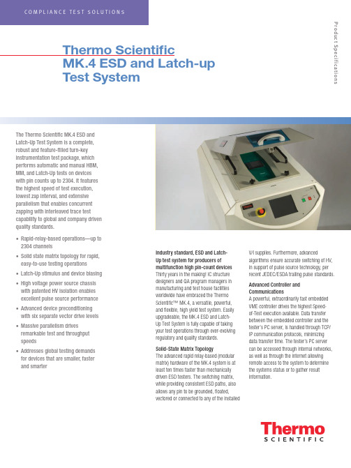
The Thermo Scientific MK.4 ESD and Latch-Up Test System is a complete,robust and feature-filled turn-key instrumentation test package, which performs automatic and manual HBM, MM, and Latch-Up tests on devices with pin counts up to 2304. It features the highest speed of test execution, lowest zap interval, and extensive parallelism that enables concurrent zapping with interleaved trace test capability to global and company driven quality standards.• Rapid-relay-based operations—up to 2304 channels• Solid state matrix topology for rapid, easy-to-use testing operations • Latch-Up stimulus and device biasing • High voltage power source chassis with patented HV isolation enables excellent pulse source performance • Advanced device preconditioning with six separate vector drive levels • Massive parallelism drives remarkable test and throughput speeds• Addresses global testing demands for devices that are smaller, faster and smarterThermo ScientificMK.4 ESD and Latch-up Test SystemIndustry standard, ESD and Latch-Up test system for producers ofmultifunction high pin-count devices Thirty years in the making! IC structure designers and QA program managers in manufacturing and test house facilities worldwide have embraced the Thermo Scientific™ MK.4, a versatile, powerful, and flexible, high yield test system. Easily upgradeable, the MK.4 ESD and Latch-Up Test System is fully capable of taking your test operations through ever-evolving regulatory and quality standards.Solid-State Matrix TopologyThe advanced rapid relay-based (modular matrix) hardware of the MK.4 system is at least ten times faster than mechanically driven ESD testers. The switching matrix, while providing consistent ESD paths, also allows any pin to be grounded, floated,vectored or connected to any of the installedV/I supplies. Furthermore, advancedalgorithms ensure accurate switching of HV, in support of pulse source technology, per recent JEDEC/ESDA trailing pulse standards.Advanced Controller and CommunicationsA powerful, extraordinarily fast embedded VME controller drives the highest Speed- of-Test execution available. Data transfer between the embedded controller and the tester’s PC server, is handled through TCP/IP communication protocols, minimizing data transfer time. The tester’s PC server can be accessed through internal networks, as well as through the internet allowing remote access to the system to determine the systems status or to gather result information.Product SpecificationsLatch-Up Stimulus and Device Biasing The MK.4 can be equipped with up to eight 100 V four-quadrant Voltage and Current (V/I) power supplies. Each V/I supply has a wide dynamic range enabling it to force and measure very low voltage at high current levels from 100 mV/10 A to 100 V/1 A. The system’s power supply matrix can deliver up to a total of 18A of current, which is distributed between the installed supplies. These supplies are able to provide a fast and versatile means of making DC parametric and leakage measurements as well as providing latch-up pulses, while offering total control and protection of the DUT.Advanced Device PreconditioningThe MK.4 system provides the most advanced device preconditioning capability available. The DUT can be vectored with complex vector patterns, providing excellent control over the device. Each pin can be driven using one of the 6 different vector supplies. The patterns can be up to 256k deep, running at clock speeds of up to 10 MHz. Device conditioning is easily verified, using the read back compare capability available on every pin.Thermo Scientific MK.4 Scimitar™Software Makes Programming Easy, while Providing Unsurpassed Programming FlexibilityThe MK.4 Windows®-based Scimitar operating software empowers users with the flexibility to easily set-up tests based on industry standards or company driven requirements.Device test plans can be created by importing existing text based device files, on the testers PC server or off-line from a satellite PC containing the application. The software also provides the capabilities to import test plans and device files from previous Thermo Scientific test systems.Test vectors from your functional testers can also be imported into the application. And of course, the vector application allows manual creation and debug of vector files.Device test plans and results are stored in an XML data base, providing unsurpassed results handling, sorting and data mining capabilities.Parallelism Drives Remarkable Test Throughput SpeedsThe MK.4 software enables ESD testing of up to twelve devices at one time using the multisite pulse source design.Embedded VME power supplies eliminate any communication delays that would be seen by using stand alone supplies. The embedded parametric (curve tracing) supply also provides fast, accurate curve tracing data to help you analyze your devices performance.The systems curve tracer can also be used as a failure analysis tool by allowing the comparison of stored, known good results, versus results from a new test sample or samples.Ready for Today’s Component Reliability Demands and Anticipating Those to Come ESD and Latch-Up testing of electronic and electrical goods can be very expensive aspects of the design and manufacturing process. This is especially true as market demands for products that are smaller, faster and smarter become the standard rather than the exception. The Thermo Scientific MK.4 leverages the technology and know- how gained over three decades of test system experience, as well as our in-depth participation and contributions to global regulatory bodies governing these changes, enabling today’s products to meet both global and industry-driven quality standards.The real key to our customers’ success is in anticipating what’s next. And to ensure that our customers possess the ability to evolve quickly to meet all change factors with efficiency and cost effectiveness.As such, the strategically-designed, field upgradeable architecture of the MK.4 system ensures a substantial return on investment over a very considerable test system lifecycle, as well as better short- and long-term qualityand ESD and Latch-Up test economies.Custom fixtures include universal package adaptors to enable the industry’s lowest cost-in-service high pin count device fixturing yetdevised. (2304-pin, Universal 1-mm pitch BGA package adaptor shown.)100W V/I Performance Thermo Scientific MK.4: eight-V/I configuration. Powerful V/Is can deliver a total of 800 W to the DUT, enabling complex testing of all advanced high power processors on your product roadmap.Solid state matrix topology for rapid, easy-to-use testing operations. Design ensures waveform integrity and reproducibility.General SpecificationsHuman Body Model (HBM) per ESDA/JEDEC JS-001-2014, MIL-STD 883E, and AEC Q100-002 25 V to 8 kV in steps of 1 V Test to multiple industry standards in one integrated system; no changing or alignment of pulse sources.Wizard-like prompts on multi-step user actions MachineModel (MM) per ESDA STM5.2, JEDEC/JESD22-A115, andAEC Q100-003, 25 V to 1.5 kV in steps of 1 VIntegrated pulse sources allow fast multi-site test execution.Latch-up testing per JEDEC/JESD 78 test pin and AECQ100-004Includes preconditioning, state read-back and full control of each.Rapid Relay-based operations at least 10 times faster thanrobotic-driven testersSuper fast test speeds.Test devices up to 2304 pins Systems available configured as 1152, 1728 or 2304 pins.Waveform network: Two, 12 site HBM (100 pF/1500Ω)and MM (200 pF/0Ω) pulse sources address up to 12devices simultaneouslyPatented design ensures waveform compliance for generations to come.Multiple device selection When multiple devices are present; graphical display indicates the devices selectedfor test; progress indicator displays the current device under test (DUT), along withtest status information.Unsurpassed software architecture Flexible programming, easy to use automated test setups, TCP/IP communication. Enables use of device set-up information Increased efficiency and accuracy from other test equipment, as well as deviceinformation import.Event trigger output Manages setup analysis with customized scope trigger capabilities.High voltage power supply chassis Modular chassis with patented HV isolation enables excellent pulse sourceperformance.Power supply sequencing Provides additional flexibility to meet more demanding test needs of integratedsystem-on-chip (SOC) flexibility.Manages ancillary test equipment through Plug-n feature allows the user to control external devices, such as scopes or heatstreams or other devices the Scimitar Plug-ins feature as required for automatedtesting.Pin drivers for use during Latch-Up testing Vector input/export capability from standard tester platforms and parametricmeasurements.256k vectors per pin with read-back Full real-time bandwidth behind each of the matrix pins.Six independent vector voltage levels Test complex I/O and Multi-Core products with ease.Up to 10MHz vector rate (programmable) Quickly and accurately set the device into the desired state for testing from an internalclock.Comprehensive engineering vector debug. Debug difficult part vectoring setups with flexibility.Up to eight separate V/I supplies (1 stimulus and 7 bias supplies) capability through the V/I matrix High accuracy DUT power, curve tracing, and Latch-up stimulus available; design also provides high current.Low resolution/high accuracy parametric measurements, using an embedded Keithley PSU With the optional Keithley PSU feature (replaces one V/I, nA measurements are achievable, allowing supply bus resistance measurement analysis to be performed.Multiple self-test diagnostic routines Ensures system integrity throughout the entire relay matrix, right up to the test socket Test reports: pre-stress, pre-fail (ESD) and post-fail data,as well as full curve trace and specific data pointmeasurementsData can be exported for statistical evaluation & presentation.Individual pin parametrics Allows the user to define V/I levels, compliance ranges, and curve trace parametersfor each pin individually.Enhanced data set features Report all data gathered for off-line reduction and analysis; core test data is readilyavailable; all data is stored in an easy-to-manipulate standard XML file structure. Interlocked safety cover Ensures no user access during test. All potentially lethal voltages are automaticallyterminated when cover is opened. Safety cover window can be easily modified toaccept 3rd party thermal heads.Dimensions60 cm (23.5 in) W x 99 cm (39 in) D x 127 cm (50 in) H© 2016 Thermo Fisher Scientific Inc. All rights reserved. Windows is a registered trademark of Microsoft Corporation in the United States and/or other countries. All other trademarks are the property of Thermo Fisher Scientific and its subsidiaries. Results may vary under different operating conditions. Specifications, terms and pricing are subject to change. Not all products are available in all countries. Please consult your local sales representative for details.Africa-Other +27 11 570 1840 Australia +61 2 8844 9500 Austria +43 1 333 50 34 0 Belgium +32 53 73 42 41 Canada +1 800 530 8447 China +86 10 8419 3588 Denmark +45 70 23 62 60 Europe-Other +43 1 333 50 34 0Finland /Norway/Sweden+46 8 556 468 00France +33 1 60 92 48 00Germany +49 6103 408 1014India +91 22 6742 9434Italy +39 02 950 591Japan +81 45 453 9100Latin America +1 608 276 5659Middle East +43 1 333 50 34 0Netherlands +31 76 579 55 55South Africa +27 11 570 1840Spain +34 914 845 965Switzerland +41 61 716 77 00UK +44 1442 233555USA +1 800 532 4752Thermo Fisher Scientific,San Jose, CA USA is ISO Certified. CTS.05102016Product SpecificationsScimitar Software FeaturesSummary Panel with easy navigation among device componentsWizard-like prompts on multi-step user actionsControl of external devices through the use of Scimitar’s user programmable Plug-in capabilities, in addition to the Event Trigger Outputs, which provide TTL control signals for external devices, such as power supplies or for triggering oscilloscopesFlexible parametric tests that are defined and placed at an arbitrary position within the executable test plan.Comprehensive results viewer that provides:• ESD and Static Latch-up data viewing capabilities• Curves viewer with zooming capabilities and the ability to add user comments• Data filtering on the following criteria – failed pins, failed results, final stress levels• A complete set or subset of results using user defined parameters• Sorting in ascending or descending order by various column criteriaTree-like logical view of the tests and test plans.Flexible data storage that provides the ability for the end-user to query the dataSeamless support of existing ZapMaster, MK.2, MK.4, and Paragon test plansCurve tracing with curve-to-curve and relative spot-to-spot comparisonOff-line curve analyzing, including third-party generated waveformsCanned JESD78A test (static latch-up only) that can be defined automaticallyPause/Resume test capabilitiesIntermediate results viewingAutomated waveform capture capability and analysis using the embedded EvaluWave software feature。

Execution Object StructureExecution ObjectContains information TestStand needs to run a sequence, its steps, and any subsequences it calls. You can suspend,interactively debug, resume, terminate, or abort executions.Thread ObjectRepresents an independent path of control flow.Report ObjectContains the report text. The process model updates the Report object, and the sequence editor or user interface displays it.Call StackLists the chain of active sequences waiting for nestedsubsequences to complete. The first item in the call stack is the most-nested sequence invocation.Root SequenceContext ObjectRepresents the execution of the least-nested sequence invocation that contains a list of steps and calls to other sequences.SequenceContext ObjectRepresents the execution of a sequence that another sequence called.Current StepRepresents the executing step of the currently executingsequence in the call stack.Architecture OverviewTestStand Sequence EditorTestStand development environment for creating, modifying,executing, and debugging sequences.Custom User InterfacesCustomizable applications that, depending on mode,edit, execute, and debug test sequences on a test station. User interfaces are available in several different programming languages and include fullsource code, which allows you to modify them to meet specific needs.Process ModelsDefine the operations that occur for all test sequences,such as identifying the UUT, notifying the operator of pass/fail status, generating a test report, and logging results. TestStand includes three fully customizable process models: Sequential, Parallel, and er Interface ControlsA powerful set of ActiveX controls and support APIs for creating custom user interfaces.TestStand EngineA set of DLLs that provides an extensive ActiveX Automation API for controlling and interacting with TestStand. The TestStand Sequence Editor, User Interface Controls, and user interfaces use this API.Sequence File ExecutionsCreated by the TestStand Engine when you execute a test sequence using the sequence editor or a user interface.AdaptersAllow TestStand to call code modules in a variety of different formats and languages. Adapters also allow TestStand to integrate with various ADEs to streamline test code generation and debugging.Code ModulesProgram modules, such as LabVIEW VIs (.vi ) or Windows Dynamic Link Libraries (.dll ), that contain one or more functions that perform a specific test or action. TestStand adapters call code modules. Built-In Step TypesDefine the standard behaviors for common testing operations. Some step types use adapters to call code modules that return data to TestStand for furtheranalysis. Other step types perform standard operations,such as calling an executable or displaying dialog boxes.User-Defined Step TypesDefine a set of custom step properties and default behaviors for each step of that custom type. You can also define data types.TemplatesCreate custom sequences, steps, and variables to use as templates to build sequence files.OVERVIEW CARDNI TestStandTMSystem and ArchitectureNI TestStand is flexible test management software that offers the following major features:•Out-of-the-box configuration and components provide a ready-to-run, full-featured test management environment.•Numerous methods for modifying, configuring,and adding new components, which provide extensibility so you can create a test executive that meets specific requirements without altering the core TestStand Engine. You can upgrade to newer versions of TestStand without losing your customizations.•Sophisticated sequencing, execution, anddebugging capabilities, and a powerful sequence editor that is separate from the user interfaces.•User interface controls for creating custom user interfaces and sequence editors.•You can also create your own user interface in any programming language that can host ActiveX controls or control ActiveX automation servers.•Example user interfaces with source code for National Instruments LabVIEW, National Instruments LabWindows ™/CVI ™, Microsoft Visual Basic .NET, C#, and C++ (MFC).•An open language interface that provides support for many application development environments (ADEs). You can create code modules in a variety of ADEs and call pre-existing modules or executables.• A comprehensive application programminginterface for building multithreaded test systems and other sophisticated test applications.•Integration with third-party source code control packages.•Deployment tools to aid in transferring a test system from development to production.TestStand Sequence EditorCode ModulesResultsResultsResultsResultsResultsResultsResultsResultsCustom User InterfacesUser Interface (UI)ControlsApplication Programming Interface (API) TestStand EngineSequence File ExecutionsUser-Defined Step TypesSequence File ExecutionsNo ModelTest Socket 0Execution UUTUUTUUTTest Socket 1Execution UUTUUT TestSocket nExecution UUTUUTUUT UUT UUTUUTUUTUUTProcess Model Result ProcessingSchema DefinitionsDatabase LoggerReport GeneratorADO/ODBCThread Object 0Thread Object n Sequence File GlobalsStepsMain Step GroupStepsCleanup Step GroupParametersSequencesLocal VariablesAdapters.VI.DLL, .OBJ, .LIB, .C.DLL .DLL, .EXE .DLL, .EXE.PRG .SEQLabVIEW Adapter LabWindows/CVI Adapter C/C++ DLL Adapter .NET Adapter ActiveX/COM Adapter HTBasic Adapter Sequence AdapterTypesSequence FileParallel Process ModelBatch Process ModelSequential Process ModelProcess Model Sequence File ExecutionTestSocket nExecution Test Socket 1Execution TestSocket 0Execution Oracle . . .SQL ServerReport ObjectExecution ObjectCall StackRootSequenceContextObject 0SequenceContextObject 1SequenceContextObject nStep Object 0Step Object n. . .Current StepMicrosoft Access Process Models. ... ..XMLHTMLASCII-Text. . .Sequence File Execution FlowSequence File ExecutionsYou can execute a sequence directly, or you can execute a sequence file through a process model Execution entry point,such as Test UUTs and Single Pass.Process Model Sequence File ExecutionWhen you start an execution through a process modelExecution entry point, the process model defines how to test the UUTs. The Sequential model tests one UUT at a time. The Parallel model tests multiple independent test sockets at the same time. The Batch model tests a batch of UUTs using dependent test sockets.Process Model Result ProcessingThe TestStand Engine collects the results of each step that executes into a result list. Process models use the result list to generate reports and log data to databases. Unit Under Test (UUT)Device or component that you are testing.Test Socket ExecutionFor each test socket, or fixture, in the system, the Parallel and Batch models launch a separate test socket execution that controls the testing of UUTs in that test socket.Report GeneratorThe report generator traverses test results to create reports in XML, HTML, and ASCII-text formats. You can fully customize the reports.Schema DefinitionsSchema definitions define SQL statements, table definitions,and TestStand expressions that define how to log results to a database. You can fully customize the schemas.Database LoggerThe database logger traverses test results and exports data into database tables using schema definitions.Sequence File StructureSequence FileContains any number of sequences, a set of data types and step types the sequence file uses, and any global variables that sequences in the sequence file share.SequencesContain groups of steps, local variables, and parameters used for passing data between steps and subsequences.TypesSequence files contain definitions of all data types and step types that its sequences use. Variables and properties in a sequence are instances of data types. Steps in a sequence are instances of step types.Sequence File GlobalsStore data you want to access from any sequence or step within the sequence file in which you define the sequence file global variable.Setup, Main, Cleanup Step GroupsTestStand executes the steps in the Setup step group first,the Main step group next, and the Cleanup step group last.By default, a sequence moves to the Cleanup step group when a step generates an error in the Setup or Main step group.Local VariablesStore data relevant to the execution of the sequence. You can access local variables from within steps and code modules defined in a sequence.ParametersUse parameters to exchange data between calling and called sequences.StepsPerform built-in operations or call code modules. A step is an instance of a step type, which defines a set of step properties and default behaviors for each step.373457B-01 Apr07. . .. . .. . .National Instruments, NI, , NI TestStand, and LabVIEW are trademarks of National Instruments Corporation. Refer to the Terms of Use section on /legal for more information aboutNational Instruments trademarks. Other product and company names mentioned herein are trademarks or trade names of their respective companies. For patents covering National Instruments products,refer to the appropriate location: Help»Patents in your software, the patents.txt file on your CD, or /patents .© 2003–2007 National Instruments Corporation. All rights reserved.Printed in Ireland.StepsSetup Step GroupTemplatesFlow Control Sequence Call Statement LabelMessage Popup Call Executable Property Loader FTP FilesSynchronization Steps Database Steps IVI-C Steps LabVIEW UtilityPass/Fail Test Numeric Limit Test Multiple Numeric Limit Test String Value Test Action Built-In Step TypesYou can use the fully customizable TestStand developmentenvironment to create, modify, execute, and debug sequences. You can also use the sequence editor to modify step types and process models. You can customize the environment by docking, auto-hiding, and floating panes to optimize your development tasks. TheDevelopment EnvironmentOVERVIEW CARD NI TestStand TMSystem and ArchitectureTestStand includes separate user interface applications developed in LabVIEW, LabWindows/CVI, Microsoft Visual Basic .NET,C#, and C++ (MFC). Because TestStand includes the source code for each user interface, you can fully customize the userinterfaces. You can also create your own user interface using any programming language that can host ActiveX controls orcontrol ActiveX automation servers. With the user interfaces in operator mode, you can start multiple concurrent executions, set breakpoints, and single-step. In editor mode, you can modify sequences, display sequence variables, sequence parameters,step properties, and so on.TestStand Sequence Editor Overview User Interface OverviewPrinted DocumentationNI TestStand Quick Start GuideUse this document for system requirements andinstallation instructions. This document also contains information about the different TestStand licensing options.NI TestStand Release NotesUse this document to learn about new features and upgrade information.Using TestStandUse this manual to familiarize yourself with the TestStand environment and the basic features you use to build and run test sequences.Using LabVIEW with TestStandUse this manual in conjunction with the Using TestStand manual to learn how to use LabVIEW with ing LabWindows/CVI with TestStandUse this manual in conjunction with the Using TestStand manual to learn how to use LabWindows/CVI with TestStand.NI TestStand Reference ManualUse this manual to learn about TestStand concepts,architecture, and features.Online HelpNI TestStand HelpUse this help file to learn more about the TestStand environment and the TestStand User Interface Controls and Engine APIs. The NI TestStand Help also includes basic information about using an ActiveX automation server.NI TestStand VIs and Functions HelpUse this help file to learn more about TestStand-specific VIs and functions. This help file is accessible only from LabVIEW.Cards and PostersNI TestStand User Interface Controls Reference Poster Use this poster to learn about the controls available for writing custom user interfaces for TestStand.NI TestStand API Reference PosterUse this poster as an overview of the TestStand API. This poster lists the properties, objects, methods, and APIinheritance of the TestStand API.L i s t B a r Lists the currentlyopen sequence files and executions.S e q u e n c e F i l e W i n d o wE x e c u t i o n V i e wR e p o r t V i e wS e q u e n c e V i e wLists steps in the sequence and step group for the sequence file you select in the list bar.Displays the threads,call stack, and steps for the execution you select.Displays the report for the execution you select.Displays sequences and other items in a sequence Displays the threads,call stack, and stepsthat an execution runs.When executioncompletes, displays thereport for theexecution.User Manager WindowAdministers groups, users,login names, pass-words, and privi-leges.UsersDisplays users for the test station. Output Pane Displays output messages that expressions and code modules post to theTestStand Engine.Call Stack Pane Displays the nested sequence invocations for the thread you select.sequence editor provides familiar LabVIEW, LabWindows/CVI, and Microsoft Visual Studio .NET debugging tools, including breakpoints, single-stepping, stepping into or over function calls, tracing, a Variables pane, and a Watch View pane. In the TestStand Sequence Editor, you can start multiple concurrent executions, execute multiple instances of the same sequence, and execute different sequences at the same time. Separate Execution windows display each execution. In trace mode, the Execution window displays the steps in the currently executing sequence. When you suspend an execution, the Execution window displays the next step to execute and provides single-stepping options.Templates List Organizes custom sequences, steps,and variables you can use as templates for building sequence files.Step Settings PaneSpecifies the settings for the step, such as code module parameters, switching, flow control, and post actions.Variables Pane Displays the variables andproperties, including the values, that steps can access at run time.StepPerforms built-in operations or calls code modules.ProjectOrganizes sequence files and code module files in folders.Workspace PaneManages projects for source code control (SCC) integration and deployment. TestStand inte-grates with third-party SCC pack-ages to add files, obtain the lat-est versions of files, and check files in and out.Watch View Pane Monitors the values of specifiedvariables, properties,and expressions during an execution.Threads Pane Contains a list of threads in the current execution.Insertion Palette Displays step types and templates you can insert into sequence files.GroupsDisplays groups that users belong to.。

船舶英语口语主编:付锦云主审:梁卫武武汉船舶职业技术学院二00九年六月CONTENTSPart One Ship Common PatternsLesson 1 Oral Shipbuilding English ……………………………………………………Lesson 2 Ship Fitter English ……………………………………………………………Lesson 3 Piper English …………………………………………………………………Part Two Business Telex and LettetLesson4 A Telex About Shipprepairing ………………………………………………Lesson 5 Bid To Success ……………………………………………………………Part Three EstimateLesson 6 Discussing Estimates ………………………………………………………Part Four Reconnaissance of WorkLesson 7 Docking Arrangement ………………………………………………………Lesson 8 Reconnaissance Of Work ……………………………………………………Lesson 9 Reconnaissance of Work ……………………………………………………Lesson 10 Reconnaissance of Work ………………………………………………………P art five After IndockLesson 11 Contact After Indock …………………………………………………………Lesson 12 Start Work …………………………………………………………………Lesson 13 Daily Contact …………………………………………………………………Part Six SurveyLesson 14 Ask for Certificate ……………………………………………………………Lesson 15 Hull Survey …………………………………………………………………Lesson 16 Docking Survey ………………………………………………………………Lesson 17 Deck Survey …………………………………………………………………Lesson 18 Steering Gear Survey …………………………………………………………Lesson 19 Main Engine Survey …………………………………………………………Lesson 20 Trouble Survey ………………………………………………………………Lesson 21 Sea Trial ………………………………………………………………………Part Seven AcknowledgementLesson 22 Check Acknowledgd Lis t …………………………………………………Part Eight Work Finish and Account BalanceLesson 23 Discussion On Bill ………………………………………………………………Lesson 24Sending out the Bill ………………………………………………………………Part Nine Business Negotiation and Sign tile ContractLesson 25 Business Negotitation ………………………………………………………Lesson 26Sign The Contract …………………………………………………………附录:船舶常用词汇表Part One Ship Common PatternsLesson 1 Oral Shipbuilding English1.1 船厂生活用语Life in the Yard1.您好!(第一次见面)How do you do?2.您好!见到您很高兴。
Piping Systems Inspection and TestingTable of Contents1.Piping Systems Inspection and Testing Scope2.Check List3.Field Inspection Procedure for Pipe Testing4.Extent of Testing5.Test Procedures6.Line Completion, Flushing and Testing, Acceptance Procedure7.ReferencesFORMS (Refer to forms section)RB26C01 P iping Test System RegisterRB26C02 I nspection Record for Piping Release for Flushing and Pressure TestingRB26C03 I nspection and Test Record for Piping Completion and Certificate for Flushing, Pressure Testing, Blowing, Reinstatement and CompletionRB26C04 I nspection and Test Record for Underground PipingRB26C05 P ressure Test Record1. Piping Systems Inspection and Testing1.1 ScopeThe purpose of this section is to provide guidelines to Company personnel, in particular to the Construction Specialists, for the inspection and testing of piping systems.Primary responsibility for quality is that of the subcontractor who shall satisfy himself through his own quality system that specified requirements are met.It is the responsibility of the Construction Specialists supported by the Welding Engineer to ensure that the subcontractor is in fact effectively applying his quality system and obtaining acceptable results.The following specialist organizations are also implicated:∙For welding, non destructive and destructive testing firms.∙Possibly third party inspector to meet Authorities requirements.Depending on the particular project, their services may be included in the piping subcontractor's scope or alternatively they may be directly controlled by Company.Piping generally involves onsite or offsite prefabrication of spools. This activity may in some circumstances be part of a construction subcontract and controlled from site.It is important that the quality systems put into place for piping works adequately cover the activities of these specialist organizations and of the prefabrication shops. Responsibility for their day-to-day supervision is that of the Piping Construction Specialist supported by auditing by the Quality Assurance Manager and by the Welding Engineer for specifically welding matters.Subsequent sections 15.2 to 15.6 are in effect checklists of points requiring surveillance, inspection or testing. They are intended as a reminder and a help to the Construction Specialist. However, they are no substitute for reading and familiarizing oneself with the subcontract, requisitions, specifications, standards and drawings. In case of conflict it is these project specific documents which prevail.The subcontractor creates his own quality system, which includes proposing the inspection and testing record forms to be used. Their suitability shall be judged by the Quality Assurance Manager in consultation with the Construction Specialist (see Reference 15.7.1).The set of inspection and test record forms attached to this section:∙May be used as a basis to review the subcontractor's forms.∙May be imposed on the subcontractor as a self contained system, should the latter's forms be considered to be unsuitable.2. Check List∙Institute system to ensure that pipespools shipped to site have been accepted and fully documented for visual/dimensional inspection, traceability, heat treatment and NDE before leaving the prefabrication shop.∙Check "Authorities" lines for proper installation and identification, matching material certificates and other authority job requirements.∙Check that all administrative back up is available on iso's.∙Verify that required vents at high points and drains at low points are correctly installed.∙Check that the proper size pipe, flange ratings, origins and destinations are in accordance with the drawings and specifications.∙Check that necessary swages, reducers and branch connections are correctly located.∙Verify that the proper type of material has been installed throughout the pipe system, especially in equipment, pumps, compressors etc.∙Check specifications for headroom in walk areas and overhead clearances in drive areas.∙Specifications may require relief-valves and pressure gauges to be checked in the subcontractor's shop. This should be checked as early as appropriate and tagged.∙Steam tracing requires inspection for length and size of tracer, branches (if allowed), trap, details, etc.∙Care should be taken when lines change specification at valves, etc. to make sure that required specifications are carried to the specified break point.∙Are jack screws required at orifice flanges or flanges with spectacle blinds?∙Check the specifications for the type of nipple required. Various nipples may be XH or alloy.∙Are blinds, spacers etc., installed at the locations called for?∙Relief valve stacks to the atmosphere, usually, require drain holes at low point. Some require weather hoods. Check project specification for the proper installation.∙Verify that both, piping- and instrument specifications and details have been utilized.∙Verify that proper tags are installed on equipment.∙Do mudlegs on steam lines require reinforcing pads, weepholes, nipples?∙Do mudlegs have clearance for expansion of the main header?∙Verify the requirements for sentinel drilling.∙Verify that the proper dope on screwed connections has been used.∙Check the insulation clearance between the adjacent pipe lines, equipment, structures, flooring, etc.∙Check the cleanliness of pipe, fittings, spools, etc. prior to installation.∙Check the use of specified graphite compounds or other lubricating mediums on bolts, studs, etc. (Note also where not to be employed).∙Check the location of valves for accessibility and operability.∙Check the location of valves to permit observation of instruments while operating the valve.∙Check that the material/equipment allowed to remain outside, is stored properly, if not immediately required for installation.∙Check that finger and/or foot traps are eliminated.∙Check that safety measures are observed and safe practices employed.∙Survey the steam tracing requirements early.∙Special attention must be paid to the slope of lines.2.1 Valves∙Verify the flow direction of globe, check and control valves.∙Check the manufacturer's name tag description with the stock code number, description, trim, etc.∙Verify the operability of valve chain wheels.∙Verify that rising of the valve stem is free of obstructions. Are valve stem protectors required.∙If special packing is required institute and maintain a tagging system.∙Check the specifications for drains- and/or flushing connections to valve bodies.∙Check the specifications and the installation of a valve bypass.∙Verify valve lubrication requirements.2.2 Bolts and Studbolts∙Verify bolts or studbolts requirements at each connection.∙Verify the dimensions of bolts or studbolts.∙When other than the standard studbolts are required, verify the stamp or color code on end of studbolts.∙Check the equipment specifications for the flange bolting requirements and verify installation.∙Make sure that all bolts or studbolts are installed and the nuts are tight at each connection. (Studbolts must have equal projection beyond nuts).2.3 Gaskets∙Check the specification for type, size, material and color coding.∙Verify the alignment of the gasket.∙Check the equipment specification for gasket requirements and verify the installation thereof.∙For testing only, other than line specification gaskets may be installed. (Punch list should specify the right gasket.)2.4 Small Bore Piping at Pumps and Other Equipment∙When the trim material is supplied by the vendor, verify that material used meets the specification.∙Check the pump piping trim installation against the pump vendor prints and the piping trim drawings (cooling water, lubricating oil, etc.).∙Verify the specification and material of pump plugs. All equipment openings must be checked.∙Check the specifications for pickling requirements.∙Check the specifications for stress relieving.2.5 Pipe Supports∙Verify the type and proper installation of pipe supports, especially major supports. Small bore pipe supports are normally field designed, and verify that they are sufficient.∙Verify the requirement of anchors/guides on high temperature steam systems.∙Inspect the application, i.e. clamps, hangers, etc. and if same are in accordance with drawings and specifications.∙Check all pipe supports on insulated lines for sufficient (insulation) clearance, location, and the welding requirements.∙In all instances verify that any line designed to transport gaseous vapors is, when hydrotesting is required, sufficiently designed and supported for hydrotesting.∙Check all spring hanger installations for type required and the correct settings.∙Verify that all lines, flanged to equipment, are not placing undue stress on the equipment (nozzle).∙Check that all lines will allow for the required expansion for both test and service pressures (temperatures).2.6 Seal Welding∙Check specifications for lines requiring seal welding and verify that total thread has been sufficiently welded.∙Check all equipment for seal weld requirements.2.7 Insulated Lines∙Verify correct installation of support clips, shoes and guides on lines.∙Check clearances between other lines, conduit tubing, equipment, etc. for proper spacing.∙Verify that temporary or permanent flanges for screen/ filter removal are properly installed so as to allow removal if required.∙Verify that specified printing or other corrosion protective measures have been applied.∙Verify installation of reinforcing (nozzle) pad ventilation nipple.∙Maintain current hydrotest records so that up-to-date information of lines ready for insulation may be given to insulation/painting subcontractors.2.8 Alloy Lines∙Verify that pre-heat/post-heat, stress relieving etc. has been properly completed. Maintain project records of same.∙Establish program to identify, tag, color code, etc., of all various types of alloy - from initial receipt until erection.∙Check alloy valves and gaskets against the specification, tag, color code, material (valve body ' trim), stock code number and description, etc.2.9 Orifice Runs∙Check the specification for required straight length of pipe, without weld, upstream and downstream of orifice flanges.∙Check the specification for location of taps (horizontal, vertical or under an angle).2.10 TestingThe testing operation will have been determined by the preparation of the testing systems. Pretest inspections are indicated in the check list.Additionally:Assure that test gauges are calibrated regularly. Permanent identification of test gauge traceable to calibration record shall be available.Assure that control valves are excluded from test.Assure that test gauges are set at high point.Verify that check-valves are not being pressurized against the flapper (seat)Assure the check valves do not block the flow of other lines included in the test system. (The check-valve flapper shall be removed or blocked in "open" position.)Assure that vents are open when filling the test system.Assure that flushing of the test system(s) can be accomplished.Assure that blocking arrangements for spring supports are provided, when required (compensation for stress during testing).Assure installation of a test blind before a closed valve. (Do not test, pressurize, against closed valves).3. Field Inspection Procedure for Pipe Testing3.1 GeneralThis procedure describes the cleaning, testing and inspection of equipment and piping systems.∙Test media and pressures as indicated, in the Line Designation Tables and on the equipment drawings, shall be followed. No deviation from test media and/or pressures specified shall be permitted, without prior approval of Engineering.∙Normally all piping shall be tested hydrostatically, using (non saline) drinking water, plant water, fire water or any other approved test media.∙For austenitic stainless steel piping and equipment, the testing water shall be clean and free of silt and shall have a chloride content of less than 12 ppm, or demineralized water.∙Austenitic stainless steel piping and equipment shall be flushed after testing with demineralized water or passivated water.∙When hydrostatic testing is considered not practical it may be substituted by a pneumatic test, however, only with prior agreement between Company and client. Pneumatic testing, using air or other non-flammable gas, may be specified if thepresence of any liquid in a system would cause operational difficulties e.g.:Catalyst LinesEquipment having internal insulation or other linings subject to damage by a test liquid.Instrument air systems.Lines for which a pneumatic test is approved shall be clearly marked on the test record sheet and Line Designation Table.∙All tests are normally to be witnessed by the client's representative and recorded on Company's test record sheets, which shall be signed by client's, Company's and subcontractor's representatives.The test record shall include for each test:∙Identification of piping system∙Line number and size∙Termination points of system∙Test medium∙Test pressure∙Start time∙Finish time∙Duration∙Date of test∙Signature and names of representatives.∙Test gauge I.D. & calibration date3.2 Preparation for TestingBefore testing, all equipment and piping shall be thoroughly cleaned of all dirt, welding slag and construction debris or other foreign matter.∙Tanks and drums shall be opened for inspection and the interiors thoroughly cleaned. The client's Start-up Engineer shall be present at final inspection to check internals against drawings. Cleaning of tanks shall be as per applicable Codes.∙Manhole covers are to be installed with permanent gaskets after final inspection.∙All temporary strainers must be installed before testing.∙Towers shall be inspected and checked to be sure that all internals are in place and that the trays are clean.∙Insulation or painting shall not be applied over welds, flanges and/or other mechanical joints prior to hydrotesting.∙Restrictions which interfere with filling, venting or draining, such as orifice plates, shall not be installed until testing and flushing is completed.∙Pressure gauges and the like which form a permanent part of the finished project are not to be installed until the system or unit has been tested and flushed.∙For hydrostatic testing, all piping and specifically those in other than liquid service, shall be adequately supported, using additional temporary supports where necessary. Spring or counterweight types of supports on these lines shall be provided with temporary supplementary supports designed to carry the full fluid test load.∙All expansion joints shall be inspected for correct installation and proper restraints prior to test.∙Control valves shall not be a part of the test system. Where bypasses are provided the test shall be performed through the bypass. Where necessary temporary spools shall be used in place of the control valves.∙Water should not be allowed to enter any of the following:- Compressor cylinders "- Pumps and turbinesInstruments and instrument lines - (testing of process piping up to the first block valve of the instrument lines.) ∙Vents shall be provided at high points of all vessels or connecting piping, to expel air. Drains shall be provided at all low points. Venting through high point flanges is acceptable where test systems do not warrant the installation of a vent. Filling the test system shall only be started after it has been verified that the high point vent is open.∙All floats in equipment shall be removed and the proper location of test blanks shall be checked before charging the system with the test medium.4. Extent of Testing4.1 Piping∙Piping which connects to lines installed by others shall be isolated from these lines by valves or test blanks. When it is necessary to include portions of such lines in the test, the client shall be consulted during test loop preparation stage todetermine the test requirements.∙To facilitate the testing of piping systems, vessels and equipment may be included in the system only when the test pressure specified is equal to or less than that for the vessels and equipment and a suitable testing medium is used.∙Pumps, compressors and turbines shall not be subjected to the field test pressure.∙Lines and systems which are open to the atmosphere, such as drains, vents, open safety valve discharges do not require pressure testing. These lines shall be examined, by any suitable means, to determine that all joints are properly made.Snuffing steam lines and similar shall be service tested.∙Safety valves, rupture discs and other pressure relieving devices shall not be subjected to the piping test pressure.∙Instrument piping from orifice flanges to the first block valves shall be tested with the piping test system. Unions on the downstream side of the block valves shall be broken to avoid introducing foreign matter in the instrument lines. Connections to instruments shall be made only after testing has been completed. Do not subject the pneumatic transmitters, pneumatic receivers, controllers, valve positioners, control valve diaphragms, etc. to test pressure.∙The testing of pneumatic instrument transmission lines should be under the direction of Company's Instrument Engineer who will specify the testing procedure, using vendor's recommendations where applicable. The testing procedure shall besubmitted to the client for obtaining approval, prior to testing.∙Underground pressure lines, such as pressure sewers, drains, etc. shall be hydrostatically tested The test pressure shall be as indicated in the Line Designation Tables or as shown on the underground piping drawings.∙Each section of gravity sewer system shall be hydrostatically tested.∙Lines containing check valves shall have the pressure source upstream of valve.4.2 Branch Reinforcements∙Each reinforcement pad (or section thereof) shall be tested with air at max. 6 bar gauge. A bubble test solution such as Sherlock, Snoop or equivalent, shall be applied to inspect all welds.∙The pipe weld of the branch connection (pipe to pipe), while bubble testing the reinforcing pad, will have been tested when the pressure gage reading remains constant.∙When testing a testsystem verify that the nipple or nipple holes of the reinforcing pad are open, so that the pipe weld of the branch connection (pipe to pipe) will be tested.∙In case of air tests, flange bolting shall not be tightened during testing of the system.4.3 Equipment∙As far as practicable, the piping test pressure shall be carried through all equipment, to assure tightness at nozzle connections.∙All new field fabricated vessels shall be hydrostatically tested in place.∙The test pressure and test medium shall be in accordance with the equipment drawings and or specifications.∙Equipment and piping shall, in general, be tested in groups or systems comprising vessels, heat exchangers and piping for which the maximum allowable test pressure (test pressure at least the minimum of every component) DOES NOT EXCEED THE MAXIMUM TEST PRESSURE OF ANY COMPONENT IN THE SYSTEM.∙When vessels are to be tested separately, verify that all nozzles and other connections for piping are blanked or disconnected. When testing piping, connecting to equipment and vessel, pipe connections are to be blanked and vents and drains of vessels are to be left open.∙At completion of testing/flushing, air cooler bundles are to be blown out with air.∙The pressure at the equipment low point will be checked when hydro-testing. The test pressure as indicated on the equipment drawing shall be increased by the static head to arrive, at the equipment's low point, test pressure.4.4 Instrument Items∙Gauge glasses and liquid level chambers etc., should be tested, as an integral part of the pipe line or equipment to which they are connected, using very clean water.∙Prior to pressure testing verify that the test pressure of the test system is not higher than the design test pressure of each component. Any instrument not meeting this requirement shall be removed from the piping and/or equipment, and the line shall be plugged, capped or blanked.∙Consult the Instrument Engineer about the specific testing requirements of the instrument hook-up lines.5. Test Procedures5.1 Hydrostatic Test∙Pressure is to be applied by means of a pump.∙Verify whether installation of a so called "sun relief valve" is required. This in relation to outside temperature and the test procedure (duration).∙The filling hose from the pressure generator shall be connected to the lowest drain point of the system. The pressure generator shall not be connected to a test-system until ready to test, and shall be disconnected immediately after the test is completed. The pressure generator shall be disconnected when not attended.∙The pressure generator and equipment to be tested are to be provided with separate indicating test pressure gauges. These gauges are to have a test certificate and will be checked calibrated periodically. Cross checking of pressure gauges can be achieved by installing a three-way-valve.∙The final test pressure shall be maintained to permit complete inspection of all joints for leakage or signs of failure. Any connection leaking during a pressure test shall be repaired and retested to the specified test pressure. When all joints arechecked for signs of failure and do not leak the pressure generator shall be shut off and the pressure held for a duration as specified in the test procedures.∙Any lines changed in configuration, after having been tested, shall be retested unless waived by the client in writing.5.2 Pneumatic Test (Only if jointly approved by client and Company)∙Equipment to be pneumatically tested shall be thoroughly cleaned and free of oil/grease deposits.∙The required air pressure will be supplied by a compressor. The air compressor shall be of a portable type and equipped or provided with a receiver, aftercooler, oil separator and relief valve.∙The compressor shall not be left unattended during the test. When, the air compressor must be left unattended, the test system must be blocked-off first and the pressure in the system relieved.∙All pneumatic tests shall include a preliminary check of not more than 1.5 bar. The pressure shall be gradually step by step increased, providing sufficient time between steps to allow conditions to stabilize and check for leaks. All joints shall bechecked with soap suds.∙The pneumatic test pressure shall not exceed 110% of the design pressure, however, with a maximum of 7 bar gauge.∙Test pressure shall be maintained for a period of time to permit a thorough inspection of all joints for leakage or signs of failure. Any joint found leaking during a pressure test shall be repaired and retested to the specified pressure. Any lineschanged in configuration, after having been tested, shall be retested unless waived by the client in writing.∙Flanged joints shall be prepared for pneumatic testing, by taping with masking tape and punching a 1/8" (3mm) dia. hole through the tape for soaping (bubble testing).5.3 Test Pressure Gauges∙All gauges used for field testing, shall be in a good working condition with a minimum of 4½ inch in diameter and the pressure gauge range shall be such that the test pressure is within 40% and 90% of the full range.∙CalibrationTest pressure gauges shall be calibrated, prior to- and regularly during the course of the test program, using a standard Dead Weight Gauge Tester. Any gauge which does not permit a correct adjustment of the zero reading, or has an error of more than ±2½% of the full scale range, shall be discarded. New gauges shall be calibrated too, prior to use.5.4 Miscellaneous∙Prior to hydro-testing piping systems, air at approximately 1.5 bar gauge may be used as a preliminary test to locate major leaks, etc. thereby avoiding the necessity of draining the system to make repairs.∙Equipment, holding for any length of time a testing medium, must be checked and vented regularly to relieve any pressure- or vacuum build up by temperature changes or "gas" forming.∙For prohibitors agents in the test media (corrosion protection, etc.) additional safety valves and other safety requirements consult with the client.∙When equipment or piping system will be tested in the field for strength, testing will be executed in accordance with the project specification and procedures and local rules and regulations. However, if the local rules and regulations are lessstringent than the project specifications and procedures, the project's shall prevail.5.5 Flushing∙Before hydrostatic testing, all lines shall be thoroughly flushed with clean test fluid.∙All steam headers and branches will be steam blown, with sufficient pressure, until steam discharge is clean and leaves no deposits on a test target-plate.∙After flushing, all strainers and filters shall be cleaned.For more details see Reference 15.7.2.5.6 Draining∙All equipment shall be completely drained after hydrostatic testing. DRAINING SHALL ONLY BE STARTED AFTER IT HAS BEEN VERIFIED THAT THE VENTS ARE OPEN.∙The rate of drainage from the equipment shall be controlled in respect to the inflow of air to the equipment to prevent formation of a vacuum or partial vacuum.∙Piping systems shall be drained of the test liquid. Check valves shall be opened to ensure that test liquid and/or other entrapped deposits are drained/removed.5.7 Chemical Cleaning∙Subsequent to flushing and testing, certain lines may require chemical cleaning (e.g. compressor suction lines, intercoolers, interstage and bypass lines, lubricating and seal systems, etc.). Such lines will be defined on the Line Designation Table and the chemical cleaning procedure is specified in a separate specification.6. Line Completion, Flushing and Testing, Acceptance Procedure6.1 Defining and Managing Test SystemsIn the first place test systems must be defined such that every element of piping to be tested throughout the project is included in one test system or another. Thus all pipework is tested.A test system, which does not necessarily coincide with the piping of a whole functional system, is an ensemble of piping which is tested on the same occasion. Its limits are set by blind flanges and within the system there may be temporary jumpers and pup pieces. In addition there shall be the necessary drains, vents, pressure gauges and connections to make the test.For flushing and blowing other temporary connections may have to be made and temporary filters installed.Test systems are defined by marki ng limits on P&ID’s. Then connections are detailed on isometric drawings. Depending on the size and nature of the project, test systems may be defined by the Company Home Office Engineering Department or by Company on site with the cooperation of the piping subcontractor.6.2 Completion of Construction and Preparation for TestingWhatever the arrangements made to define the test systems, it is the task of the Construction Superintendent assisted by the Piping Construction Specialists to organize the series of tests to cover all the pipework. This necessitates the establishment and updating ofP&ID’s and isometric drawings, with the test systems numbered. From these master documents, “test packs” are issued to those executing the tests generally the piping subcontractors and to those supervising, namely Company.In the meantime, prefabrication and site erection of piping and supports with its associated non-destructive testing, visual and dimensional checks shall have been proceeding. Records of these operations are made in the isometric dossiers and on welding and NDE records.When the piping subcontractor considers that a section of pipework, (a set of isometrics, ideally corresponding to a test system) is complete he shall declare so officially, inviting Company to punchlist. (See reference 15.7.3 for further details).Once the punchlist items have been completed in construction, the piping shall be adapted and connected to give the configuration shown on the test pack defining the test system.The above described successive steps are recorded on form RB26C02, refer to forms section. The issue of this form, duly signed off is confirmation that the test system is ready for the start of flushing, testing and blowing. The completed form is added to the test pack. 6.3 Flushing, Testing and BlowingCompleting form RB26C02 for a test system, leads to opening of a form RB26C03. This form for a given test system enables successive stages of:∙Flushing∙Pressure testing∙Blowing∙Reinstatement∙Release for heat tracing/painting/insulation (where applicable)to be recorded.The pressure test is recorded in more detail on form RB26C05, refer to forms section.The case of underground piping is covered by a single form covering all operations to completion, testing and backfilling. This is form RB26C04.6.4 TrackingSuccessive steps of these operations for the whole project are tracked by marking-up the “Master” P&ID’s and isometrics. In addition tracking is done using form 26C01, copy attached.7. References。
The Student JourneyBefore the testReceive test invitationTake the testAfter the test•You will receive an invitation to take your Versant test by email before the test, from the address ****************Please check your spam folders if the email does not arrive in your inbox.•The email provides a test link, username and password, and informs you that the test will be recorded.•When you click on the link you will be directed to the test platform where you can follow the on screen instructions.•The test must be completed in the window of opportunity indicated by the university.•Please follow the instructions provided to ensure your system and environment (test room) is suitable.•Please read the official guide to familiarize yoursef with the test, available on the UniMi SLAM site.•After clicking on the link to go to the platform for the test,you will be instructed to enter your username and password (provided in the invitation email) to start the test.•You will be instructed to enter your username and password (see the invitation email) to start the test.•Next, you will be asked to take a selfie using your device's camera or upload a photograph.•You must also tick boxes to consent to being monitored.•The duration of the test is about 50 minutes.•The test cannot be paused and you must take the full test in one sitting.•To learn more about the test and read advice on how to be successful, please visit: https://www.unimi.it/en/study/language-proficiency/placement-tests-and-english-courses/placement-test•Results of the linguistic portion of testing will be available after the test, but final decisions are subject to approval of the university based on proctoring reports. The university will inform you of the next steps.•You will be able to download the test report. An email will arrive describing how to do that after the test.Versant English Placement TestTechnical SupportIn Italian| e-Mail or phone | Monday-Thursday 8:30-17:30, Friday 8:30-17:00https://pearson.it/versant-online-english-testIn English|e-Mail or chat/ 24/7:https://versanthelp.hirepro.in/。
teststand seq 加密原理Teststand seq encryption principle is an essential aspect of ensuring the security and integrity of test systems and sequences. 加密原理是测试系统和序列安全和完整性的重要方面. Encrypting teststand seq is a necessary measure to protect sensitive data and intellectual property from unauthorized access and manipulation. 加密teststand seq是保护敏感数据和知识产权免受未经授权的访问和篡改的必要措施. There are various encryption algorithms and techniques available for securing teststand seq, each with its strengths and weaknesses.有各种加密算法和技术可用于保护teststand seq,每种都有其优点和缺点. Understanding the encryption principles and implementing appropriate measures is crucial for safeguarding the teststand seq from potential vulnerabilities and threats.理解加密原理并实施适当的措施对于保护测试系统和序列免受潜在的漏洞和威胁至关重要.One of the fundamental encryption principles is the use of cryptographic algorithms to transform plaintext data into an unintelligible form, known as ciphertext.一个基本的加密原理是使用密码算法将明文数据转换为一种不可理解的形式,称为密文. This process involves the use of keys to encrypt and decrypt the data, with theencryption key used to convert plaintext to ciphertext and the decryption key used to reverse the process and retrieve the original data.这个过程涉及使用密钥来加密和解密数据,加密密钥用于将明文转换为密文,解密密钥用于反向处理和检索原始数据. The strength of the encryption lies in the complexity and randomness of the key, making it extremely difficult for unauthorized parties to decipher the ciphertext without the corresponding decryption key.加密的强度在于密钥的复杂性和随机性,使得未经授权的各方极其难以在没有相应的解密密钥的情况下解密密文. This principle forms the basis for securing teststand seq, ensuring that only authorized users with the correct decryption key can access and manipulate the sequence data.这一原理构成了保护测试系统和序列的基础,确保只有具有正确解密密钥的授权用户才能访问和操纵序列数据.In addition to cryptographic algorithms, the encryption principle also encompasses the use of secure communication protocols and access controls to protect the transmission and storage of teststand seq data.除了密码算法,加密原理还包括使用安全通信协议和访问控制来保护teststand seq数据的传输和存储. Secure communication protocols such as SSL/TLS provide encryption and authentication mechanisms to establish a secure channel for data exchange between testsystems, preventing eavesdropping and tampering by malicious entities.安全通信协议如SSL/TLS提供了加密和认证机制,用于在测试系统之间建立安全通道进行数据交换,防止恶意实体窃听和篡改. Similarly, access controls can be implemented to restrict unauthorized access to teststand seq data, ensuring that only authorized personnel have the necessary permissions to view and modify the sequences.同样,可以实施访问控制来限制未经授权的访问teststand seq数据,确保只有授权人员具有必要的权限来查看和修改序列. By integrating these additional measures with cryptographic algorithms, the encryption principle provides a comprehensive approach to safeguarding the confidentiality and integrity of teststand seq data.通过将这些额外措施与密码算法整合在一起,加密原理提供了一种全面的方法来保障teststand seq数据的机密性和完整性.Furthermore, the encryption principle considers the need for key management and secure storage to prevent unauthorized access to the encryption keys and ensure their confidentiality and availability for decryption processes.此外,加密原理考虑了密钥管理和安全存储的需求,以防止未经授权的访问加密密钥,确保它们的机密性和可用性用于解密过程. Key management involves the generation, distribution, and revocation of encryption keys, as well as the implementation of keyrotation to mitigate the risk of key compromise and unauthorized access.密钥管理涉及生成、分发和撤销加密密钥,以及实施密钥轮换以减轻密钥泄露和未经授权访问的风险. Secure storage mechanisms, such as hardware security modules (HSM) or secure key vaults, are utilized to store encryption keys in a protected environment and prevent them from being compromised or stolen.安全存储机制,如硬件安全模块(HSM)或安全密钥库,用于在受保护的环境中存储加密密钥,防止它们被泄霞或被盗. By addressing the key management and secure storage aspects, the encryption principle reinforces the protection of teststand seq data and minimizes the risk of unauthorized decryption and manipulation.通过解决密钥管理和安全存储方面的问题,加密原理加强了对teststand seq数据的保护,并最小化了未经授权的解密和篡改的风险. Overall, key management and secure storage play a crucial role in upholding the confidentiality and integrity of encrypted teststand seq data.Another important consideration in the encryption principle is the performance impact of encryption and decryption processes on teststand seq execution.在加密原理中的另一个重要考虑因素是加密和解密过程对teststand seq执行的性能影响. Encrypting and decrypting large volumes of data can introduce overhead and latency,potentially impacting the real-time execution of test sequences and overall system performance.加密和解密大量数据可能会引入开销和延迟,可能影响测试序列的实时执行和整体系统性能. Therefore, it is essential to evaluate the computational overhead of encryption algorithms and implement efficient encryption techniques to minimize the performance impact on teststand seq execution.因此,评估加密算法的计算开销并实施高效的加密技术以最小化对teststand seq执行的性能影响至关重要. This may include the use of hardware-accelerated encryption/decryption, parallel processing, or optimized algorithmsto ensure that the encryption and decryption processes do not significantly hinder the execution of teststand seq.这可能包括使用硬件加速的加密/解密、并行处理或优化算法,以确保加密和解密过程不会显著阻碍teststand seq的执行. By addressing the performance impact of encryption and decryption, the encryption principle seeks to maintain the operational efficiency and responsiveness of test systems while ensuring data security and confidentiality.通过解决加密和解密的性能影响,加密原理旨在保持测试系统的运行效率和响应速度,同时确保数据的安全性和保密性.In conclusion, the encryption principle for teststand seq is a multifaceted approach that encompasses cryptographic algorithms,secure communication protocols, access controls, key management, secure storage, and performance considerations.总之,测试系统和序列的加密原理是一个多方面的方法,涵盖了密码算法、安全通信协议、访问控制、密钥管理、安全存储和性能考虑. By integrating these elements, the principle aims to provide a comprehensive and robust framework for protecting teststand seq data from unauthorized access, manipulation, and performance degradation.通过整合这些元素,该原则旨在为保护teststand seq数据免受未经授权的访问、篡改和性能下降提供一种全面和健壮的框架. Adhering to the encryption principle is essential for ensuring the security and integrity of test systems and sequences, particularly in environments where confidentiality and data protection are paramount.遵循加密原理对于确保测试系统和序列的安全和完整性至关重要,特别是在机密性和数据保护至关重要的环境中. Ultimately, the encryption principle serves as a critical component of a comprehensive security strategy for teststand seq, mitigating the risk of data breaches and unauthorized access while upholding the operational efficiency of test systems.最终,加密原理作为测试系统和序列综合安全策略的关键组成部分,有助于减轻数据泄露和未经授权访问的风险,同时保持测试系统的运行效率.。