Emigma中文手册_说明
- 格式:pdf
- 大小:1.92 MB
- 文档页数:29

恩尼格码密码机制作图解这个作品是2013年无线电单片机竞赛的亚军。
感谢所有支持这个作品的你们!在对称加密学当中,恩尼格码机绝对是承前启后的存在。
它将密码学研究从以前的语言文字学中心完全转移到了数学身上。
在这里牵涉的密码并不是我们平时邮箱、银行帐号那种狭义概念,那种顶多叫做口令。
这里说的密码就是通过某种转换规律方式,把一篇文章变得面目全非,非常人能阅读,以达到保密效果。
这篇文章适于电脑控、军事控、历史控、数学控阅读,请做好烧脑准备。
第1步:在对称加密学当中,恩尼格码机绝对是承前启后的存在。
它将密码学研究从以前的语言文字学中心完全转移到了数学身上。
在这里牵涉的密码并不是我们平时邮箱、银行帐号那种狭义概念,那种顶多叫做口令。
这里说的密码就是通过某种转换规律方式,把一篇文章变得面目全非,非常人能阅读,以达到保密效果。
这篇文章适于电脑控、军事控、历史控、数学控阅读,请做好烧脑准备。
这是我们的初号机。
以下教程将手把手教你如何完美山寨史上著名的德国恩尼格玛密码机(以下称哑谜机,不清楚历史的可以到维基、百度等地方脑补一下)。
这个基于Arduino 的开源程序能够加解密任何哑谜机M4型(海军型)的信息。
这个第一台全功能开源完美哑谜机复制品是根据sketchsk3tch写的《Kid’s Game to Arduino Enigma Machine》(从儿童玩具到Arduino恩尼格玛机)所作。
采用多路复用LED电路,仅用38个针脚的115个发光二极管和4个针脚的36个按键所连接的整个电路,全靠在键盘回路里准确放置的电阻以及P型号晶体管得以实现。
要不然,4个16段显示器,以及每个按键上的LED将大幅增加所需针脚总量,即使用了Arduino。
英尼格玛机Enigma使用教程与练习前言:针对某些同学对于二战时期德军使用的密码机英尼格玛机Enigma的兴趣,我在这里编写一套关于使用英尼格玛机模拟器加密和解密的教程。
希望大家能喜欢。
我在编写这套教程时使用的是D. Rijmenants在2008年编写的模拟器,其他的模拟器也是和这个大同小异,但是为了方便我就用这个模拟器编写教程了。
里面会用到一定量的德语作为破译内容(毕竟这个是德国人的玩意),我会附上中文翻译的,所以不必担心看不懂。
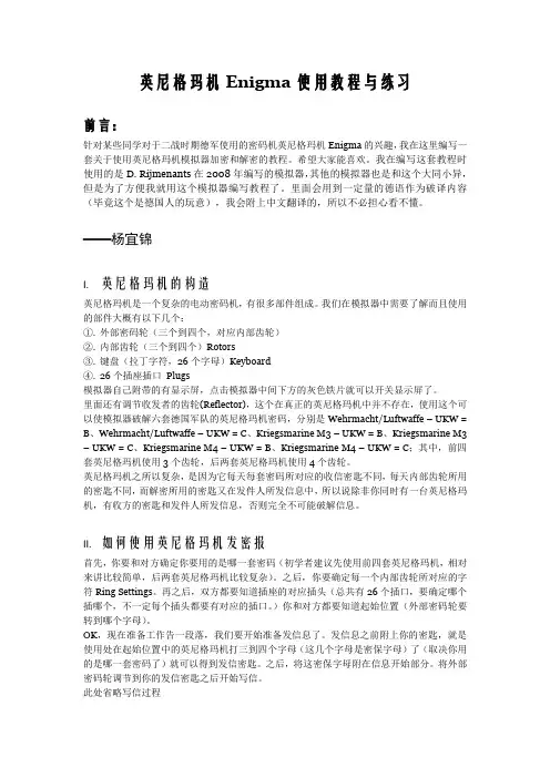
——杨宜锦I. 英尼格玛机的构造英尼格玛机是一个复杂的电动密码机,有很多部件组成。
我们在模拟器中需要了解而且使用的部件大概有以下几个:①.外部密码轮(三个到四个,对应内部齿轮)②.内部齿轮(三个到四个)Rotors③.键盘(拉丁字符,26个字母)Keyboard④.26个插座插口Plugs模拟器自己附带的有显示屏,点击模拟器中间下方的灰色铁片就可以开关显示屏了。
里面还有调节收发者的齿轮(Reflector),这个在真正的英尼格玛机中并不存在,使用这个可以使模拟器破解六套德国军队的英尼格玛机密码,分别是Wehrmacht/Luftwaffe – UKW = B、Wehrmacht/Luftwaffe – UKW = C、Kriegsmarine M3 – UKW = B、Kriegsmarine M3 – UKW = C、Kriegsmarine M4 – UKW = B、Kriegsmarine M4 – UKW = C;其中,前四套英尼格玛机使用3个齿轮,后两套英尼格玛机使用4个齿轮。
英尼格玛机之所以复杂,是因为它每天每套密码所对应的收信密匙不同,每天内部齿轮所用的密匙不同,而解密所用的密匙又在发件人所发信息中,所以说除非你同时有一台英尼格玛机,有收方的密匙和发件人所发信息,否则完全不可能破解信息。
II. 如何使用英尼格玛机发密报首先,你要和对方确定你要用的是哪一套密码(初学者建议先使用前四套英尼格玛机,相对来讲比较简单,后两套英尼格玛机比较复杂)。

0521-03AMay 2006FUSE PANELTechnical PracticeFDP 101010/10 GMTNEBS Level 3 CertifiedFEATURES2 isolated groups (busses) of 10 GMT fuses in each (15Amps/GMT position)Polarity insensitive (+/-24 or +/- 48 Vdc) battery voltageThis panel can operate at 200 Amps of output current per panel (100 Amps per Bus)Barrier terminal strips for fused outputs and isolated returns (grounds)Three sets of Form C relay contacts are provided to extend alarmsOne set of alarm contacts for each; MAJOR Bus A, MAJOR Bus B and MINOR External Input AlarmMINOR External Input Alarm provided on the ground signal applied to the input pinCable management bar (aka. towel bar) on rear panel includedFive spare fuse holders provided on the panel’s faceplateSingle 1.75” mounting height (single panel space)Two sets of mounting brackets are supplied (1” & 1-3/4” spacing), both sets of brackets are universal for 19” and 23” racks, with flush and offset mounting optionsNEBS level 3 certified, with zone 4 earthquakeP.O.Box1306,NewportBeach,California92663~Phone:714-751-0488~Fax:714-957-1621~***************************1. GENERAL DESCRIPTION1.1. The Newmar model FDP 1010 Fuse Panel provides up to 20 circuits for the distribution of DC power to equipment. Each of the 20 circuits is individually protected by a GMT style telecommunication fuse located on the panel's faceplate. Alarm circuits are provided to indicate and extend alarm conditions when faults occur. Normal Operation LEDs are provided to indicate the status of each bus in the panel.1.2. Input wiring is connected to a high current, 2-hole lug input block located at the rear of the panel. Each group of fuses or bus has its own completely isolated inputs, allowing the distribution of two battery voltages through the same panel.1.3. The power is distributed to the load side equipment through GMT style fuses. There are 10 fuses per fuse group and two groups per panel. Each fuse position is available for installer connection at the rear of the panel. A designation card is provided for keeping records of which position is connected to which equipment and what amperage is to be used. 1.4. Each panel is equipped with dummy fuses in all unused positions. The panel also can hold up to 5 spare fuses in the faceplate.1.5. Alarm circuits are provided to alert service personnel of fault conditions. A fuse alarm is caused when any of the GMT distribution fuses opens. A red Fuse Alarm LED on the faceplate will illuminate and the green Normal Operation LED will extinguish to signal a fuse alarm and also the appropriate MAJOR relay contacts will change states. These fuse panels have common (C), normally open (NO) and normally closed (NC) terminals for both Major and Minor alarms. A Major alarm being a fuse or power failure in that bus and a Minor alarm being an external alarm. The external alarm is ground activated (20mA required to activate alarm.) Note, the use of the alarm contacts is optional, if you do not wish to extend the alarms, you don’t have to do anything with the alarm pins.The “Normal” condition of the relay exists when the panel is powered up without any blown fuses or externally activated alarms.The red External Alarm LED on the units face plate will light when a ground is connected to the MINOR “Alarm In” terminal (20mA max. signal required to activate alarm.)1.6. The N250120-N-L0521 Fuse Panels are made from 0.050" steel and painted black. Single rack height panels are shipped with two sets of universal brackets (1” & 1-3/4” spacing) that will fit both 19" and 23" wide racks and use only one 1.75" panel space. The panel has a clear L shaped lexan to protect the wiring connections on the back of the panel.2. APPLICATION2.1. The N250120-N-L0521 Fuse Panels are designed to be used in the distribution of DC power. They are rack mount panels that can provide fused DC power to up to 20 individual circuits, or 10 pieces of equipment, providing redundant battery feeds to each.3. CIRCUIT DESCRIPTION3.1. Power is connected to the fuse panel via ¼” studs on 5/8” centers located at the rear of the panel (torque 5.5 ft-lbs.) These inputs are high current stud blocks that supply current to the fuse panel. Connect the battery return cable to the stud input that is labeled “RTN” and the Battery supply cable is connected to the terminals labeled “BAT”.3.2. Distribution of current from each bus is provided by GMT style fuses. Each bus has 10 fuse holders for distribution; the fuses are labeled F1 to F10 on each bus. Each fuse position is made available at the rear of the fuse panel. Maximum output current of each fused position is rated at 15 Amps, provided the maximum bus current or BDFB fuse is not exceeded (each bus is rated at 100Amps max.)3.3. Fuse alarm circuitry provides 1 set of form “C” contacts (C, NO and NC) for each type of alarm (Major Bus A, Major Bus B and Minor-Ext). In the event of a fuse or external alarm, the proper relay will change states, providing a connection between the Normally Open “NO” and Common “C” terminals. The normally closed “NC” terminal will open to high impedance. The MINOR indicates an external ground input alarm (aka; bay or rack alarms.) Ground activates the external alarm input.4.INSTALLATIONPlease read completely before beginning. WARNING:Installation should only be performed by an experienced Installer familiar with DC power distribution systems.4.1. Unpack and inspect the Newmar Fuse Panel for possible damage incurred during shipping. If damage is found, file a claim immediately with the carrier, and notify Newmar.4.2. Once the panel is unpacked, verify that there are two sets of mounting brackets (1” & 1-3/4” spacing). Adjust the position and orientation of the correct mounting brackets on the fuse panel, such that it will fit the rack you wish to mount the panel in. Single rack height panels have a universal bracket that allows the panel to be mounted on either 19" or 23" wide equipment racks and can be installed for flush mounting of the fuse panel, or for a 5" offset mounting.4.3. Mount the panel on the equipment rack using the thread forming #12-24 rack mounting screws and tooth lock washers provided.WARNING:For safety reasons all wiring should be done with the power source removed (when possible).4.4. Remove the distribution fuse feeding the input cables that are to be connected to the new panel. Using input cables specified by the Job Engineer, hook up the input cables to the input terminal block on the fuse panel (“BAT” & “RTN” for each bus). Each high current input terminal uses a two hole compression lug (1/4” on 5/8”, torque to5.5 ft-lbs).4.5. The battery outputs (“BAT”) are available at the terminal blocks (#6 screw, up to 10awg fork) at the rear of the panel. Each fuse position is numbered and that circuit is available at the terminal block position with the same number.4.6. All battery return (“RTN”) connections are also terminated on barrier strips (#6 screw, up to 10awg fork). Note, these returns are isolated from the chassis frame.4.7. This panel has MAJOR Bus A, MAJOR BusB and MINOR External alarms. Each alarm has a common (C), normally open (NO) and normally closed (NC) alarm contact.The Minor External Input Alarm is used for alarms that originate outside the panel (bay alarms). A ground signal is supplied from another device in the bay to activate this alarm. In an alarm the “C” contact will short to the “NO” contact, and the “NC” will open. Connect the alarm connections as per your alarm system requirements. Newmar recommends you fuse the alarm battery supply (ABS) to 1A or less to protect the alarm wiring and circuitry.4.8. CHASSIS GROUND;For safety reasons, and as recommended by NEBS, the chassis should be electrically connected to the rack ground. From step 4.3. the panel should already be ground to the rack via the #12-24 thread forming rack screws and outside tooth lock washers. In addition to grounding via the mounting brackets, it is recommended you ground the chassis using a ground cable and the #10 bolt and locks on side of chassis (#10 screw torque; 2ft-lbs or 2.7Nm).4.9. Power up the panel by installing the distribution fuses supplying the panel. The panel should power up with the Normal Operation LED illuminated and without any red LEDs illuminated, and the relays should be in the “Normal” state (“C” connected to “NC”).4.10. If you wish to verify the fuse alarm circuit, you can insert a blown fuse into one of the empty fuse holders. The red Fuse Alarm LED should light and the Normal Operation LED should extinguish and the appropriate “MAJOR” alarm extension relay should change states to extend the alarm. If you wish to verify the externally activated alarm you can connect a GND to the External Alarm In, the External Alarm LED should light and the MINOR-external alarm extension relay should change states to provide the alarm extension.4.11. Install panel output distribution fuses as required. Use the provided designation card to keep a record of which equipment is connected to which circuit and what the fuse rating is. Be careful not to overload the panel bus or BDFB fuse position rating supplying the panel.Note:If you have any questions, suggestions, or problems, please don't hesitate to call Newmar Technical Support at (714) 751-0488, (email) ********************************or contact us through the Internet at http//. Your input helps us in our ongoing product improvement process that benefits both of us. Thank You.5. SPECIFICATIONS5.1. Voltage -/+24 or -/+48 VDC Typical-/+22 to -/+58 VDC Max.5.2. Current/Fuse 15 Amps Maximum5.3. Current/Bus 100 Amps Max.5.4. Current/Panel 200 Amps5.5. Output Fuse GMT Style Fuse Holders 5.6. Output/Bus 10 Fuses (20 per panel) 5.7. Output/Panel 2 Busses per Panel5.8. Input Block Two ¼” Stud on 5/8 center 5.9. Output Block #22 AWG to 12 AWG wireOr fork/ring for #6 screw,10awg forks/rings will work 5.10. Alarm Block #22 AWG to 12 AWG wire or fork/ring for # 6 screw. 5.11. Relay contacts 2 Amps/58Vdc max 5.12. Relay activation Gnd, 20mA max. 5.13. Dimensions 1¾ H, 17 W,10½ D(excluding brackets) 5.14. Rack Mounting 19” and 23” Racksfor 1” or 1-3/4”Panel Spaces5.15. Weight Apprx. 8 Lbs5.16. Operating Temp. -20° to +60°C(-5° to +140°F)5.17. Color Black10 AWG fork/ring will work Compatible lugs for Input Block2 hole compression lugs for 1/4” studs on 5/8” centers (torque 5.5ft-lbs), example; Panduit® LCD2-14A 2awg wireLCD4-14A 4awg wireLCD6-14A 6awg wireLCD8-14A 8awg wire Output lugs (locking fork recommended): Ring or fork for #6 screw (up to 10awg)6. WARRANTYThis product manufactured for Newmar by Noran Tel is warranted to be free from defects from workmanship and components for a period of 2 years from the date of shipment. During this period any defective products shipped prepaid to Newmar will be repaired or replaced at our discretion and returned at no further cost to the customer. Newmar shall not be liable for any consequential or indirect damage of any type or nature, nor for any cost of reinstallation. Any product that has been subject to improper installation, unauthorized alteration, accident or misuse is rendered void of warranty.Newmar also provides a repair service for products not covered by warranty. Charges will be levied for labor, components, and transportation.To return a unit for repair contact the Newmar and obtain a Return Material Authorization Number (RMA.)Be prepared to provide the following information:1. Product Name2. Product Model Number3. Product Serial Number4. Your contact person and phone number.5. Your company name and return address Package the unit in its original shipping carton or adequate substitute, along with a clear & complete description of the problem or defect. Clearly mark the outside of the carton with the Return Material Authorization Number and send the unit to the address shown below:NEW MAR2911 W. Garry AveSanta Ana, CA 92704Phone: (714) 751-0488Fax: (714) 957-1621E-mail: ********************* Internet: 。

Eaton PDG52M1200E4RNEaton Power Defense molded case circuit breaker, Globally Rated, Frame 5, Two Pole, 1200A, 65kA/480V, PXR20 ARMS LSI w/ Relays, No TerminalsGeneral specificationsEaton Power Defense molded case circuit breakerPDG52M1200E4RN 786679286579139.7 mm 406.4 mm 209.5 mm 21.32 kg Eaton Selling Policy 25-000, one (1) year from the date of installation of theProduct or eighteen (18) months from thedate of shipment of the Product,whichever occurs first.RoHS Compliant UL 489CSACCC MarkedIEC 60947-2Product NameCatalog Number UPCProduct Length/Depth Product Height Product Width Product Weight WarrantyCompliancesCertifications1200 AComplete breaker 5Two-polePD5 Global Class A PXR 20 LSI w/ARMS600 Vac600 VNo Terminals65 kAIC at 480 Vac 100 kAIC Icu/ 100 kAIC Ics/ 220 kAIC Icm @240V (IEC) 15 kAIC Icu/ 7.5 kAIC Ics/ 31.5 kAIC Icm @690V (IEC) 65 kAIC @480/277V (UL) 100 kAIC @240V (UL)70 kAIC Icu/ 53 kAIC Ics/ 154 kAIC Icm @380-415V (IEC) 50 kAIC Icu/ 40 kAIC Ics/ 105 kAIC Icm @440V (IEC) 35 kAIC @600/347V (UL)30 kAIC Icu/ 25 kAIC Ics/ 63 kAIC Icm @525V South Africa (IEC)50 kAIC Icu/ 30 kAIC Ics/ 105 kAIC Icm @480V Brazil (IEC)1200 AEaton Power Defense MCCB PDG52M1200E4RN 3D drawing Power Xpert Protection Manager x64Amperage Rating Circuit breaker frame type Frame Number of poles Circuit breaker type Class Trip TypeVoltage rating Voltage rating - max Terminals Interrupt rating Interrupt rating rangeTrip rating 3D CAD drawing packageApplication notesConsulting application guide - molded case circuit breakersPower Xpert Protection Manager x32BrochuresStrandAble terminals product aidPower Defense brochurePower Defense molded case circuit breaker selection posterPower Defense technical selling bookletCatalogsPower Defense molded case circuit breakers - Frame 5 product aid Power Xpert Release trip units for Power Defense molded case circuit breakersMolded case circuit breakers catalogCertification reportsPDG6 CSA certificationPDG5 CB reportPDG5 CCC certificationPDG5 CSA CertificationPDG6 CCC certificatePower Defense Declaration concerning California’s Proposition 65EU Declaration of Conformity - Power Defense molded case circuit breakersPDG5 UL authorizationInstallation instructionsPower Defense Frame 2/3/4/5/6 voltage neutral sensor module wiring instructions – IL012316ENPower Defense Frame 4_5 flex shaft handle mech assembly instructions - IL012284ENPower Defense Frame 5 aux, alarm, shunt trip and uvr instructions(IL012201EN).pdfPower Defense Frame 5 vertical padlockable handle lock hasp installation instructions - IL012283ENPower Defense Frame 5 key interlock installation instructions -IL012294ENPower Defense Frame 5 walking beam installation instructions -IL012290ENPower Defense Frame 5 breaker status module installation instructions – IL012307ENPower Defense Frame 4_5_6 high performance flex shaft handle mech assembly instructions - IL012296ENInstallation videosPower Defense Frame 5 Trip Unit Replacement Animated Instructions Power Defense Frame 5 UVR Trip How-To VideoPower Defense Frame 5 Aux, Alarm, ST and UVR Animated Instructions.rh1Power Defense Frame 5 Shunt Trip, Aux and Alarm Trip How-To Video Power Defense Frame 5 Trip Unit Upgrade Relays Board, Animated Instructions.rhPower Defense Frame 5 Trip Unit Upgrade Wire Harnesses, Animated Instructions.rhMultimediaPower Defense molded case circuit breakersPower Defense Frame 2 Variable Depth Rotary Handle Mechanism Installation How-To VideoPower Defense Frame 5 Trip Unit How-To VideoEaton Power Defense for superior arc flash safetyPower Defense Frame 6 Trip Unit How-To VideoPower Defense Frame 3 Variable Depth Rotary Handle Mechanism Installation How-To VideoPower Defense BreakersSpecifications and datasheetsEaton Specification Sheet - PDG52M1200E4RNTime/current curvesPower Defense time current curve Frame 5 - PD5White papersMolded case and low-voltage power circuit breaker healthIntelligent power starts with accurate, actionable dataSingle and double break MCCB performance revisited Implementation of arc flash mitigating solutions at industrial manufacturing facilitiesIntelligent circuit protection yields space savingsMaking a better machineSafer by design: arc energy reduction techniquesMolded case and low-voltage breaker healthEaton Corporation plc Eaton House30 Pembroke Road Dublin 4, Ireland © 2023 Eaton. All Rights Reserved. Eaton is a registered trademark.All other trademarks areproperty of their respectiveowners./socialmedia。

FEATURES• Intuitive handling• Clearly visible LED ring and microphone button • Proven Sennheiser KE 10 microphone capsuleThe MEG 14-40-L-II features a made in Germany quality gooseneck microphone on an attractive price. A lightring indicates the spokesperson that is allowed to take the floor. It features a Sennheiser KE 10 microphone capsule with cardioid directivity for universal miking. The flexib-le element of the streamlined 40 c m gooseneck ensures precise alignment of the microphone. An XLR 5M connec-tor delivers power for the green LED ring and connects the microphone signal.SPECIFICATIONSPick-up patterncardioidFrequency response 50 Hz - 20 k HzAcoustic principle gooseneck microphone (con-denser)Output impedance @ 1 k Hz < 100 ΩSensitivity15 m V/PaMax. sound pressure level130 d B @ 1 kHz < 3 %Equivalent noise level37 dB (CCIR)26 dB (A)Power supply microphone 12 V - 48 Vphantom power (P 12 - P 48)Current consumption 3 mAPower supply signal light ring 12 - 30 V DC 1 - 18 mAgreenConnector XLR-5M TemperatureF Operation:Storage:0 °C to 40 °C(32 °F to 104 °F)-25 °C to +70 °C(-13 °F to 158 °F)ARCHITECT‘S SPECIFICATIONThe microphone shall be a pre-polarized condenser desi-gned for permanent installation or portable applications. It shall have a microphone capsule with a cardioid polar pattern with uniform 120° angle of acceptance (-3 d B). The microphone shall include a lighted ring below the capsule for indicating the activity of the microphone.It shall have a frequency response of 50 H z to 20,000 H z and be capable of handling sound input levels up to 130 d B SPL. Nominal equivalent noise level shall be 26 d BA (37 d B weighted as per CCIR 468-3). Output shall be low impe-dance balanced (< 100 Ω). Operating temperature shall be 0 °C to 40 °C (32 °F to 104 °F). The microphone shall opera-te from an external 12 V to 48 V D C phantom power source; current consumption shall be 3 m A. The lighted LED ring shall operate from an external 12 – 30 V D C power source; current consumption shall be 3 m A. The microphone shall offer radio frequency interference (RFI) shielding against intermodulation from wireless equipment or devices.The microphone shall be a gooseneck design ensuring precise alignment of the microphone. It shall incorporate a self-contained power module with an XLR 5M connector at the base, which includes connection for the lighted ring power. The microphone shall be a small-diameter goosen-eck design with a diameter of 8 m m (0.31") and an overall length of 457.2 m m (18"). Head diameter shall be 22.8 m m (0.9"). The microphone weight shall be 147 g (4.72 o z). Finish shall be matte black.The microphone shall be Sennheiser MEG 14-40-L-II.POLAR PATTERN0°330°300°270°240°210°180°150°120°90°60°30°DIMENSIONS⌀ 0.9"[22,8 m m ]PIN ASSIGNMENT1 Microphone Ground2 Microphone +3 Microphone –4 LED Ground5 LED: 12 – 30 V32145FREQUENCY RESPONSEHz501002005001k2k5k10k20kd B V-20-30-40-50-60PRODUCT VARIANTS Product FeaturesMEG 14-40 B Art. no. 504791• Gooseneck with integrated Senn-heiser KE 10 microphone capsule• RF shielding against intermodu-lation from wireless equipment/devices• Streamlined design for seamlessintegration• Premium quality made in GermanyThe MEG 14-40 features a made in Germany qualitygooseneck microphone on an attractive price. It featuresan integrated Sennheiser KE 10 microphone capsule withcardioid directivity for universal miking and a streamlined40 c m gooseneck with a XLR 3M connector. The flexibleelement ensures precise alignment of the microphone.MEG 14-40-L B Art. no. 504792• Gooseneck with integrated Senn-heiser KE 10 microphone capsule• RF shielding against intermodu-lation from wireless equipment/devices• Streamlined design for seamlessintegration• LED ring for speech indication• AC/DC lightring powering• Premium quality made in GermanyThe MEG 14-40-L features a made in Germany qualitygooseneck microphone on an attractive price. A lightringindicates the spokesperson that is allowed to take thefloor. It features a Sennheiser KE 10 microphone capsulewith cardioid directivity for universal miking. The flexibleelement of the streamlined 40 c m gooseneck ensuresprecise alignment of the microphone. A XLR 5M connec-tor delivers power for the red LED ring and connects themicrophone signal.MEG 14-40-L-II B Art. no. 506398• Intuitive handling• Clearly visible LED ring and micro-phone button• Proven Sennheiser KE 10 micro-phone capsuleThe MEG 14-40-L-II features a made in Germany qualitygooseneck microphone on an attractive price. A lightringindicates the spokesperson that is allowed to take thefloor. It features a Sennheiser KE 10 microphone capsulewith cardioid directivity for universal miking. The flexibleelement of the streamlined 40 c m gooseneck ensuresprecise alignment of the microphone. An XLR 5M connec-tor delivers power for the green LED ring and connectsthe microphone signal.COMPATIBILE PRODUCTSProduct compatible withMEG 14-40 B MAT 133, MAT 133 S-B, SL Tablestand 133-S DW MEG 14-40-L B MAT 153, MAT 153-S und MAS 1MEG 14-40-L-II B SL Tablestand 153-S DW, MAT 153-S B。
for PSAIM™version1.4 EIMp User's GuideCopyright©2006-2016Siemens Energy,Inc.All rights reserved.Siemens Energy,Inc.Siemens Oil&GasConceptual&Engineering Services(CES)4615Southwest Freeway,Suite900Houston,TX77027/energyAll other company,product and service names and logos may be trademarks or service marks of their respective companies.Any rights not expressly granted herein are reserved.While every effort is made to ensure the accuracy of content,the product documentation could contain inaccuracies or out-dated material(which includes product screenshots and images)due to the large number of product enhancements being added.As such,the documentation set is subject to change at any time without notice.Refer to the README for documentation corrections and addendum.Please note,updates to the documentation set are reflected in the next general availability major release.Table of ContentsContacting Customer Support4 Technical Support Service(TSS)4 Technical Support Website(TSW)4 Incidents reported prior to July2015(Rightnow Portal)4 Incidents reported after July2015(SIOS Portal)4 Problems Accessing TSW4 Software Update(SU)5 Software Installation Service(SI)5 Postal Mail5 About This Guide6 1Using EIMp81.1Logging In82Users and Roles92.1Role Permissions92.1.1Creating and Editing Users112.1.2Resetting the Password132.1.3Creating and Editing Roles143Privilege17 4User Group18 5Plant Topology20Contacting Customer SupportSIEMENS provides a dedicated technical support team for their Process Safety&Conceptual Engineering Software.Customers that qualify for Customer Support Services are entitled to these services.For questions related to Customer Support and whether or not you qualify,please check with the support team for verification.The program includes the following services and is subject to a user registration procedure.l Access to Technical Support Service(TSS):Customer Support for problems related to software use post installationl Access to Technical Support Website(TSW):Web site including amongst others,information such as Frequently Asked Questions and technical documentation about products.l Software Updates(SU):Request for shipment of software upgrades such as major and minor releases,and service packs(for qualifying customers and users)l Software Installation(SI):Assistance with software installationTechnical Support Service(TSS)TSS can be reached through the Customer Care Center phone number:.International and within US:+1(800)333-7421The phone is answered24x7x365.However,response to service request tickets is provided only from Monday to Friday,business hours from8:00AM to5:00PM,Central Daylight Time,excluding US national holidays. Technical Support Website(TSW)Incidents reported prior to July2015(Rightnow Portal)Access to Rightnow Portal through Operations Intelligence,Safety&Conceptual Engineering Services Customer Support Site(https:///energy/sw-support)is available to all customers registered as a TSS user.TSW contains technical information such as Technical Documentation and Useful Hints.Customers are requested to check the status of incidents reported prior to July2015in the Rightnow Portal.After July 2015,this portal will no longer accept new Incident Requests.Incidents reported after July2015will be available in the SIOS portal below.Incidents reported after July2015(SIOS Portal)Access to Siemens Industry Online Support(SIOS)(https:///cs/#?lc=en-WW)is available to all registered er must be registered at the SIOS portal to be able to request er can register directly on the portal by clicking the above URL and then clicking Register in the upper right portion of the page.Note:The SIOS portal is the recommended means for requesting support.All emails are handled directly in the support ticketing system via the web portal above and are linked to ticket numbers so a full record of all email communications is maintainedProblems Accessing TSWIn case customers are facing problems accessing the TSW,please call+1-800-333-7421Software Update(SU)Qualified customers can request for or be notified when major,minor releases,patches,service packs are available for valid and licensed versions of the software product.Alternatively,customers can contact a TSS representative using the Customer Care Center phone number provided above to receive these updates by logging a ticket.Software Installation Service(SI)Qualified customers can contact the TSS team via the customer support center to request assistance with installation of licensed softwarePostal MailSiemens Energy,Inc.Customer Services,Oil,Gas&MarineProcess Safety& Conceptual EngineeringAttn.:Customer Support Department4615Southwest Freeway,Suite900Houston,TX77027USAAbout This GuideThis application includes complete documentation in an accessible PDF-based help system.The accessible PDF format is designed to provide easy navigation online.The file can also be printed out to provide a handy desktop reference.Formatting ConventionsBold Terms in bold describe an item that you select to carry out a given task.Example:Select the Print option.Italics Italicized terms pertain to the three(3)tabs of the Properties View.Example:Design specifications are edited in the Engineering tab.Dotted Underline Text with a dotted underline represent links to another topic within the document.Example:The model is illustrated in Figure1-47.In addition to these formatting conventions,this document uses the following styled paragraphs as visual cues for online viewing.l Notes are used to offer information that supplement important points of the main text.Tips suggest certain tech-niques and procedures that may help you achieve your task quickly.Unit or Case is not required.You can install each PSAIM™component separately.You simply uncheck thecomponents you do not want to install.The service is typically installed on the same server.l See Also notices provide you with additional references to similar topics and/or concepts within the guide as well as external sources.To continue with the Environment configuration and EIMp database upgrade,refer tothe"PS Environment Tool Configuration Guide."To continue with the Environment configuration and EIMp database upgrade,refer tothe"PS Environment Tool Configuration Guide."See the topic,Troubleshooting the Configuration for more information.l Web References point you to external web sites that give additional information on the given topic./energyl Important notices provide information that are required to completing a given task.Check-in all site-level items and approve the changes.Due to limitations with SQL Server,you must install the PSAIM™and EIMp databases onthe same system where SQL Server is hosted.l Warnings tell you that failure to take or avoid a certain action could result in loss of data or application mal-function.WarningDo not power off or unplug your machine during an upgrade.1 Using EIMp1Using EIMpThe EIMp(Engineering Information Management platform)is used for controlling user access and maintaining the plant topology(COMPANY/SITE/UNIT).1.1Logging InThere are two(2)ways to log into the EIMp program:l Using Windows credentials;l Using the application username and password.T o l o g o n t o E I M punch EIMp.The"Main"dialog appears.2.For Environment Server,type the EIMp server name and click the Connect icon.3.For Environment,click the down-arrow and select the EIMp Environment from the drop-down.4.Do one of the following:l Check Login using windows credentials.ORl Uncheck the windows credentials checkbox.The User Name and Password textboxes appear.Enter the User Name and Password.To change the password,see the topic,Resetting the Password.5.Click Log In.2Users and RolesThis section covers how to add,edit and delete users and roles.2.1Role PermissionsA user can have more than one role and the access to each COMPANY/SITE/UNIT can be associated with each unique role.Read Only User has the ability to view,but not to modifyManagement User has the ability to view and perform auditing tasksInspector User has the ability to perform inspection engineering tasksEngineer User has the ability to perform all engineering tasksChampion User has the application administrator accessAvailable roles for PSAIM™S it e S et t in gsConfiguration Settings AIM_MODIFY_SITESETTINGS x x---Drawing SettingsCorrosion Monitoring SettingsActivity SettingsView Site Settings AIM_VIEW_SITESETTINGSx x x x x User Settings x x x x x x Local Drawing SettingsLocal Data Logger SettingsSelecting ProfileCustom Filter SettingsWork Offline AIM_WORKOFFLINE x x x x x Equ ipm en tActivate/Inactivity Equipment AIM_ACTIVATE_EQUIPMENT x x---Privileges and permissions assigned for each role in PSAIM™Add/Copy/Edit/Delete Equipment AIM_MODIFY_EQUIPMENTx x x--View Equipment AIM_VIEW_EQUIPMENTx x x x x Co r r o s io n Mo n it o r in gActivate/Inactivate Component AIM_ACTIVATE_COMPONENTx x---Add/Copy/Edit/Delete/Group Component AIM_MODIFY_COMPONENTx x x--View Component AIM_VIEW_COMPONENTx x x x x T MLActivate/Inactivate TML AIM_ACTIVATE_TML x x---Add/Edit/Copy/Clone TML AIM_MODIFY_TML x x x--View TML AIM_VIEW_TML x x x x x S u r v eyAdd,edit and delete Survey AIM_MODIFY_SURVEY x x x--View Survey AIM_VIEW_SURVEY x x x x x Approve Survey AIM_APPROVE_SURVEYx x---S t r u c t u r al T m inAdd or edit Structural Tmin AIM_MODIFY_STMIN x x x--View Structural Tmin AIM_VIEW_STMIN x x x x x Ac t iv it yAdd/Edit/Delete/Complete Activity AIM_MODIFY_ACTIVITYx x x--View Activity AIM_VIEW_ACTIVITY x x x x xApprove/Reject Activity AIM_APPROVE_ACTIVITYx x---D r aw in gAdd,edit and delete Drawing AIM_MODIFY_DRAWING x x x--Privileges and permissions assigned for each role in PSAIM™View Drawing AIM_VIEW_DRAWING x x x x x Data LoggerAIM_DATALOGGERxxx--At t ac h m en t an d H is t o r y Add,edit and delete Attachment AIM_MODIFY_ATTACHMENT x x x --View Attachment AIM_VIEW_ATTACHMENT x x x x x Edit/Delete History AIM_MODIFY_HISTORYx x x --View History AIM_VIEW_HISTORY x x x x x Audit Trail AIM_AUDITTRAILxx-x-R epo r t s Add or edit Reports AIM_MODIFY_REPORT x x x x -Delete Reports AIM_DELETE_REPORT x x Delete Own Delete Own-View Reports AIM_VIEW_REPORTxxxxxS APAdd or edit SAP AIM_MODIFY_SAP x x ---View SAP AIM_VIEW_SAP x x x x x HelpAIM_VIEW_HELPxxxxxPrivileges and permissions assigned for each role in PSAIM™2.1.1Creating and Editing UsersT o c r e a t e a u s e r a n d a s s i g n r o le s1.From the main menu,click User .The "User -User Role View"screen appears.2.Click the Add button()OR the Edit button().The"User Administration"screen appears.Fields with a red asterisk(*)are required.These represent the minimuminformation needed to create the user.3.Select an Application.4.Check the Active checkbox.To deactivate a user,you simply deselect(uncheck)the Active checkbox and click Save.5.For Log In,enter the Windows user name.6.Check the Is Windows User checkbox.7.Enter the user's First and Last names and an Email.8.For each Role/User Group/Privilege/Business Unit,select an available item to assign to the user and click theright-arrow()button to add it to the Selected column.To remove an item from the Selected column,select the item and click the left-arrow()button.A role with an asterisk(*)indicates that is a system role.So,you must select a resource in order toassign the system role to the user.For more information on PSAIM™roles and their assigned permissions,see the topic,About Roles.9.For system roles:From the Selected column for Roles,select the system role and click the Edit Resources button.This updates the resources for the selected role.If new user information has not been saved,a dialog appears prompting youto save the user information.Click Yes to save and continue.10.Click Save.For Application Users(not Windows Users),a password is automatically generated and the following message appears.To copy this temporary password to the clipboard,press CTRL+SHIFT+C.Upon the next log-on,you will need to reset your password.T o de l e t e a u s e r1.From the main menu,click User.The"User-User Role View"screen appears.2.Select(to highlight)the user you want to remove.A user cannot be deleted if there are Role(s),Privilege(s),User Group(s),and or Business Unit(s)associatedwith the user.3.Click the Delete button().2.1.2Resetting the PasswordWhen resetting your password,the new password must be:l Alphanumeric,consisting of only letters(a-z,A-Z)and/or numbers(0-9);l Six to fifteen characters long;l Different from the previous password.T o r e s e t t he p a s s w o r d1.Log onto EIMp.The log on page appears.2.Enter your existing password,then enter(and re-enter)the new password.3.Click Log In.2.1.3Creating and Editing RolesThis section describes how to add,edit and delete a user role. It also shows all the user(s)assigned to each role.A role with an asterisk(*)indicates that is a system role.System roles are pre-defined and cannot be edited ordeleted.T o c r e a t e(o r e di t)a r o l e1.From the main menu,click Role.The"User Role-User View"screen appears.2.Click the Add button()OR the Edit button().The"Role Administration"screen appears.Fields with a red asterisk(*)are required.These represent the minimum3.Select an Application.4.Check the Active checkbox.To deactivate a user,you simply deselect(uncheck)the Active checkbox and click Save.5.Enter a Role Name.6.For each User/Privilege/User Group,select an available item to assign to the role and click the right-arrow()To remove an item from the Selected column,select the item and click the left-arrow()button.7.Click Edit Resources,which is located at the upper,right-hand corner of the dialog box.The"Assign resources for"dialog appears.8.Check the location(s).In order to save,each application role must have at least one resource assigned to it.9.Click OK to assign the resource(s)for the application role.This returns you to the"Role Administration"screen.A resource inherits permissions for all sub-resources.For example,assigning a COMPANY to a user grantsthat user access to all SITES and UNITS.Similarly,assigning a SITE to a user grants that user to the UNITSunder the SITE.10.Click Save.T o de l e t e a r o l e1.From the main menu,click Role.The"User Role-User View"screen appears.2.Select(to highlight)the role you want to remove.A role cannot be deleted if there are User(s),Privilege(s),and/or User Group(s)associated with the role.3.Click the Delete button().3PrivilegeThis dialog shows all the user(s)who are assigned to all the available privilege(s).This dialog simply displays the users.There are no options to configure.4User GroupThis section describes how to add,edit and delete user group. It also shows all the user(s)who are assigned to each user group.T o c r e a t e(o r e di t)a u s e r g r o u p1.From the main menu,click User Group.The"User Group-User View"screen appears.2.Click the Add button()OR the Edit button().The"User Group Administration"screen appears.Fields with a red asterisk(*)are required.These represent the minimuminformation needed to create the user group.3.Select an Application.4.Enter a User Group Name.5.For each User/Role/Privilege,select an available item to assign to the user group and click the right-arrow()button to add it to the Selected column.To remove an item from the Selected column,select the item and click the left-arrow()button.6.Click Save.T o de l e t e a u s e r g r o u p1.From the main menu,click User Group.The"User Group-User View"screen appears.2.Select(to highlight)the user group you want to remove.A user group cannot be deleted if there are User(s),Privilege(s),and/or Role(s)associated with the usergroup.3.Click the Delete button().5 Plant Topology5Plant TopologyThis section describes how to configure the plant topology types(COMPANY/SITE/UNIT)and to add,edit and delete the plant topology entity.It is highly recommended you fully configure the plant topology prior to using the PSAIM™application.Changes made to plant topology is reflected in the application after10minutes.T o c o n f i g u r e t he p l a n t t o p o l o g y1.From the main menu,click Plant Topology.The"Plant Topology"screen appears.The Delete button for the Type Administration group is disabled to allow aone-time set-up.First,you define the type.2.For Type Administration,either click the Add button()OR select a plant topology type.3.Do one of the following:l To add a parent-level type,enter the Name and click Save Type.l To add a child-level type,enter the Name,then select the Parent,and click Save Type.Fields with a red asterisk(*)are required.Next,define the entity(or the plant topology data).5 Plant Topology214.For Entity Administration ,either click the Add button ()OR select a plant topology entity.5.Select a Parent from the drop-down list.6.Then,enter a Name ,Code ,and Address .7.Click Save Entity .T o de l e t e a n e n t i tyPrior to deleting a parent entity,all children must first be deleted.1.Select (to highlight)the entity you want to remove.2.Click the Delete button ().。
恩尼格码密码机制作图解这个作品是2013年无线电单片机竞赛的亚军。
感谢所有支持这个作品的你们!在对称加密学当中,恩尼格码机绝对是承前启后的存在。
它将密码学研究从以前的语言文字学中心完全转移到了数学身上。
在这里牵涉的密码并不是我们平时邮箱、银行帐号那种狭义概念,那种顶多叫做口令。
这里说的密码就是通过某种转换规律方式,把一篇文章变得面目全非,非常人能阅读,以达到保密效果。
这篇文章适于电脑控、军事控、历史控、数学控阅读,请做好烧脑准备。
第1步:在对称加密学当中,恩尼格码机绝对是承前启后的存在。
它将密码学研究从以前的语言文字学中心完全转移到了数学身上。
在这里牵涉的密码并不是我们平时邮箱、银行帐号那种狭义概念,那种顶多叫做口令。
这里说的密码就是通过某种转换规律方式,把一篇文章变得面目全非,非常人能阅读,以达到保密效果。
这篇文章适于电脑控、军事控、历史控、数学控阅读,请做好烧脑准备。
这是我们的初号机。
以下教程将手把手教你如何完美山寨史上著名的德国恩尼格玛密码机(以下称哑谜机,不清楚历史的可以到维基、百度等地方脑补一下)。
这个基于Arduino 的开源程序能够加解密任何哑谜机M4型(海军型)的信息。
这个第一台全功能开源完美哑谜机复制品是根据sketchsk3tch写的《Kid’s Game to Arduino Enigma Machine》(从儿童玩具到Arduino恩尼格玛机)所作。
采用多路复用LED电路,仅用38个针脚的115个发光二极管和4个针脚的36个按键所连接的整个电路,全靠在键盘回路里准确放置的电阻以及P型号晶体管得以实现。
要不然,4个16段显示器,以及每个按键上的LED将大幅增加所需针脚总量,即使用了ArduinoMega板但如果没用上述两个方法也不能如此简洁。
面对电路的超额需求,我们在http://stgeotronics设计了专用的PCB板。
直接跳到第10步和以后的步骤可以找到更多信息。
同时,我们以测试过的完整电子组装套装发布。


Integrated Fire Alarm Systems from BoschRemote Services Handbook21 ABOUT REMOTE SERVICESConnecting to the future 3 The Remote Portal 4The Remote Services Package52 B ENEFITS FOR YOUR DAILY WORKSupporting technicians in the field 6Troubleshooting and support with FSP-5000-RPS7Flexible user management 8 - 9 Operation and real-time awareness Up-to-date system status 10 Service and connection history 10 Maintenance and ServiceEffective service preparation 11 Efficient on-site visits 12Automatic documentation with Remote Maintenance133 MANAGING LICENSES 14 - 15ContentConnecting to the Future1 About Remote ServicesRemote ConnectUse your PC andFSP-5000-RPS toconnect andmaintain a systemRemoteMaintenanceOptimize supportduring and after yourwalk tests on your PC,tablet and phoneWhen you’re managing different security and safetysystems across many locations, technology can beyour greatest asset. Bosch helps to provide your cus-tomers with immaculate remote support and enhancedperformance while optimizing your day-to-day opera-tions. Bosch Remote Services for fire alarm systemscombines all these benefits in one cutting-edge andsecure solution which scales with your business.All Services are managed through the Bosch RemotePortal. It can be used with any browser interface onceyou are registered and a system is connected to it.The connection is encrypted and secured by the SecureNetwork Gateway and Bosch Security Servers.How to manage your fire alarm systems and how thisdirectly benefits the daily comissioning, operationsas well as maintenance work for fire alarm systems isexplained in the following chapters.31 | About Remote Services Remote PortalHow to registerThe Remote Portal can be accessed on the following Link: When first accessing the portal please register an account for your company, which will then function as an administrator account. Every new fire alarm system will connect to this account and its Remote ID. Each particular company account has a unique Remote ID assigned. This Remote ID is required when connecting a fire alarm system to the Remote Portal. System HierarchyAfter a successful login, the system overview on the starting menu, shows all connected fire alarm systems. The names of the systems result from the name as set-up in the configuration of the fire alarm system. All systems can be arranged in freely definable groups that contain multiple systems. This helps you to keep an overview on regions, customers or support groups. Additional groups can be added by clicking on the plus button in the right-bottom corner of the system over-view (see figure above).There is no limit to the depth of the nesting or combi-nation of elements at any level. The Remote Portal dis-plays the hierarchy as a tree structure (granting access to the whole hierarchy, shown on the left-hand side of the screen) and by displaying the system and group cards of the current level on the right hand side of the screen. Use the tree to navigate to any group or level of the hierarchy and cards to drill down in the hierarchy from current level.45Remote Services PackageRemote Services help to efficiently monitor, maintain and service the individual fire detection equipment, ensuring highest safety standards. In the following section you find a brief overview of the three innovative features provided in the package.1 | About Remote ServicesCity sitesOpera House, MunichRemote ConnectRemote AlertA remote internet connection that enhances your operations. Secure remote connection for:• Configuration • Service• TroubleshootingEasy setup within 30 minutes.Optimized for seamless integra-tion into RPS.Customized alerts, sent to you and your customers for additional peace of mind.Faults and alarms are automat-ically transmitted to mobile devices via SMS and E-Mail.Easy user management: define responsibilities for specific people as needed.RemoteMaintenanceMaintain your system efficiently with the integrated tool that monitors the condition of every installed device.Access live fire system data.Prepare detailed maintenance documentation while testing with a tablet-optimized interface. Stay connected with the panel while maintaining the system.Receive easy-to-understand fire system data.Service history is stored within the Remote Services Portal.Efficiency increase of at least 25%:Via simultaneous maintenance and detailed reporting.Intended end customer gets infor-mation, enabling more effective maintenance of your system.6Remote Connect from Bosch delivers unparalleled connectivity with little to no IT expertise required. Enjoy the advantages of an entirely remote configura-tion, not just a remote display. Avail yourself of the 24/7 access and availability, thus even global monitoring is no challenge anymore. Enabling a prompt reaction time significantly augments your customer satisfaction. Your assets will always be safe and protected, thanks to Remote Connect.Supporting Technicians in the Field2 Benefits for your daily workFurther benefits include the possibilities of preventive maintenance and the monitoring of detectors. As a result maintenance and travelling costs will be reduced due to shorter system downtime.7When you have successfully connected a system to the Remote Portal, you can use Remote Connect .Remote Connect allows you to connect to a fire alarm system using the Secure Network Gateway from Bosch with very few steps necessary. The configuration software FSP-5000-RPS connects to the systems as if you were on-site. If allowed by local regulations, you then may modify configuration, remotely control the system via the Remote Terminal as well as update or troubleshoot anytime and from anywhere you need to.Especially demanding applications require a lot of atten-tion during the initial set-up and commissioning phase – But oftentimes configuration experts are needed to fine-tune the system: With Remote Connect experts can now support technicians in the field remotely from their office, once an issue occurs.Troubleshooting and Support with FSP-5000-RPS2 | Benefits for your daily work - Supporting technicians in the fieldWell trained configuration experts can quickly modify necessary details and guide the local technicians as if they were themselves on-site. This way your company optimizes both costs due to a much more efficient allo-cation of staff, but also the top-line of business by pro-viding better commissioning and faster reaction times. Ultimately this creates more business opportunities for you, allowing your teams expertise to scale to its full potential.8The Remote Portal allows you to manage your systems according the way you run your business. With a highly adaptive user management you can differentiate three user levels: administrator, technician and customer. Each of them have their distinctive set of privileges on the Remote Portal and via FSP-5000-RPS.2 | Benefits for your daily work - Supporting technicians in the fieldFlexible User ManagementAdministratorTechnican AAs an Admin you can create andmanage different projects.Factory DresdenCompany CologneOpera MunichCustomer AUse RemoteMaintenance for Walktests and Sensor ReportsCan receive alerts about TroublesCan receive alerts via e-Mail or SMS when fire isdetectedTechnician A Technician A,Customer ATechnician C Customer CTechnician B Technician B, ACustomer BBy default any system within the Remote Portal is not accessible by technicians or mobile users until access is granted explicitly. Administrators always have access to all systems connected to their Remote ID. The details of these access rights are explained hereafter.92 | Benefits for your daily work - supporting technicians in the fieldAdding a technician to a group grants access to all systems of this group and the systems of any nested group. Access rights accumulate from top to bottom of the hierarchy, as explained in the following example which is illustrated in the box on the right side.Technician access can be granted either for a particular system or for a set of systems by adding a technician to a system or group respectively. Technicians access allows to view the particular systems in the Remote Portal via a browser and additionally enables access to the system via the client software such as FSP-500-RPS. For further details on granting access and permis-sion, please refer to the user section of this document.Removing AccessRemoving access is only feasible on the highest entrylevel. Based on the example, the access for Technician A can only be removed on the highest entry level of Group 1, 1-1. If access is removed at a lower level such as 2-1, removal is denied. Removal of access, when applicable, is shown via a red …-“ sign in the bottom right corner of the menu.Status AggregationCoordinating and establishing systems in a group hier-archy, results in the aggregation of status information of all the systems within a group. Each group always displays the aggregate status of all systems (in par-ticular systems functionality, connectivity and service status), with failure status appearing in the top group, displayed by the status icons. This provides a quick way to verify functionality of a large number of devices contained in a group. Further, this enables simplified navigation in case of occurring errors.Granting AccessGroup 1 - Technician A, B System 1-1 System 1-2Group 2 - Technician C System 2-1 System 2-2 - Technician DFor this example technicians A and B can access systems 1-1, 1-2, 2-1 and 2-2, whereas technician C can only access system 2-1 and 2-2 and technician D only system 2-2. Resulting access rights are shown at every level, as an example, in system 2-2 all technicians are granted access, matching the configuration shown in the example above.10Once a system is commissioned and running at the customer‘s site, you want to make sure that you are up-to-date on its performance. Remote Alert is the feature of Bosch Remote Services that guaran-tees to keep you in the loop should anything happen.In case of any event, service or alarm all subcribers will be notified, in other words, all defined recipi-ents, are immeadiately notified via E-mail or SM S. Should multiple triggering events of one specific type occur, only the initial ten events within a 24h period will be sent, reducing the number of messages in case of larger event bursts.Furthermore the Remote Portal limits total amount of SMS to 50 per day, per account. The portal alert his-tory however always shows all events, independent of whether a message was sent or not.You can decide who will be informed in case of an alarm or system troubles. Depending on your settings they will get an SMS or E-Mail notification.The following overview shows the different types of event and notification channels. SM S notifications include only a short information text of the type of event, the site and and its location, while the E-mail feature offers additional more detailed reports.Up-To-Date System StatusService and Connection HistoryWhen you select a system in the system overview on the Remote Portal, you can also get insights into the alarm and service history.Via the walktest feature within the service history you can get an overview when the last service visit was conducted. It also allows to monitor how many points were checked at a certain time as well as to check specific reports of the system and the detector.3 Operation and Real-Time Awareness113 | Operation and real-time awarenessShows if the detector is in revision mode.Effective Service PreparationIn the service industry every minute counts. Therefore, Remote Maintenance offers you live system data down to an LSN element of the complete fire alarm system. You can find this data here for each LSN loop:Using a periodical polling of the elements connected to the fire alarm system, you can get an overview on the sensor data of detectors on the LSN bus. This allows you to preemptively know the pollution state of each individual detector. There is no more uncertainty what to expect before you reach the customer site.You only need to take the specific new detectors to the customer in need for replacement. On site you can immediately start the work on critical elements, ensur-ing your customer’s business continuity. The data help-ing you to prepare the specific service visit, is illus-trated below according to the automatic fire detector range from Bosch.123 | Operation and real-time awarenessEfficient on-site VisitsWhen you are on-site to do maintenance not only every minute counts, but also you want to minimize the inter-ruption to your customer’s business. The integrated walk test feature of Remote Maintenance helps you to be faster when testing detectors. With the click of a button you start the walk test on any device with a web browser and all detectors in revision mode appear ready for the automated testing. When you introduce test gas for triggering, an optical detector will automat-ically show itself as “tested” – This way you do not need to monitor the panel display for successful triggering and the Remote Portal will handle the documentation for you.If there is a fire alarm on another loop of the system, the Remote Portal will show a pop-up warning message – depending on local regulations this feature helps you to reduce the necessary manpower for the walk testfrom two to just one technician on site.133 | Operation and real-time awarenessRepeat until alldetectors were tested…Start walktest“Use your mobile device to make use of the Remote Portal during the walktest. Select the System and Panel where you are going to test and click: …Start walktest“.Test the detectors as usualTest the detectors in the building with your usualequipment.3Get feedback from the Remote Portal everytime a detector wastested successfullyThe Remote Portal offers visual and acoustic feedback to prove immedeately if a detector was successfully tested.4Download the ReportAfter every walktest you can download a detailed Report from the Remote Portal.5Stop the walktest after testing all detectorsIf you want to continue the walktest the next day, just close the Remote Portal. To end the whole walktest, klick …Stop Walktest“.6Put the detectors you want to test in revision mode on the panel1Automatic Documentation with Remote Maintenance14Note: The Remote Portal intelligently parses licenses information from the information entered in the dialog, it is not necessary to apply special formatting or remove extra text. Multiple license codes can be added at once. Licenses added are saved in the Remote Portal for use, but only consumed when the corresponding is activated(manually or via auto-renewal). This allows having a stock of licenses in the Remote Portal for immediate use, without inactive licenses expiring inadvertently.Dear customer,please follow the steps below to add your recently purchased licenses to your account:1. Log into your account at https://2. Click the …Licenses“ tab in the top bar.3. Click the …Add Licenses“ button.4. Copy and paste the entire license information between the dashed lines to the browser dialog box and click …Add“.----- license information (begin) -----Fire panel remote services bundle:1234: 1111-2222-3333-44441235: 2222-3333-4444-55551236: 3333-4444-5555-6666----- license information (end) -----Thank you for using Remote Services.Regards,Bosch Security Systems154 | LicensingUsing Licenses and Activating ServicesSubscribing to a service for a system will start a check for available licenses. A suitable license in the Remote Portal account will be used up and subscribed to the fire alarm system for which the service is activated. Licenses are assigned from available stock - A particu-lar license‘s assignment can be checked from the infor-mation shown on the license in the Remote Portal. The remaining life-time of a license assigned to a ser-vice is shown in the service section of a device. Once the license expires the service is no longer available and requires an extension. License expiration is high-lighted in red in a device‘s service section and the sys-tems overview screen at the services icon.Auto-RenewalFor convenience and to avoid service interruptions, services can be configured for auto-renewal upon expiry. This can be done at time of service subscription or the service settings screen for a particular service: Auto-renewal requires a license to be available when renewal is due, otherwise renewal fails. Use the license management to plan and coordinate your particularlicenses in regular intervals.Managing Licenses - Future License UsageThe licenses tab provides the necessary information and actions to manage licenses. At the top of the screen current and predicted license usage is displayed, bro-ken down by service /license type:Based on the number of devices subscribed, the remaining life-time of the subscription and auto- renewal of service subscriptions, the Remote Portal predicts when additional service licenses are needed, marking the estimated demand of licenses in red. Note that this estimation will change when additional devices are subscribed to a service.Individual License Status and MaintenenceIndividual licenses are shown below the license usage section of the screen and provide information on each purchased license, the license status (avail-able, assigned and expired) as well as its validity and assigned system.Licenses that have not yet been assigned to a system (are in available state) can be removed from an account by clicking the trashcan symbol of the license. This allows you to transfer licenses to another account or to make licenses unavailable for use.License deletion is immediate and permanent. You must copy and save the license key presented in the warning dialogue in order to reuse at a later stage.Bosch Sicherheitssysteme GmbH Robert-Bosch-Ring 585630 GrasbrunnGermany。
Manual-1MLM 103MIC/LINE MIXEROPERATORS MANUAL WEAR PARTS:This product contains no wear parts.MLM 103 CONNECTIONINPUTSThe MLM 103 has ten balanced Euroblock Inputs. Use only shielded cable. For best noise rejection use two-conduc-tor-plus-shielded wire, even for unbalanced operation.Connect the non-inverting (positive) audio lines to the “+”terminals, and the inverting (negative) lines to the “–”terminals. Connect the shields to the “ground” terminals.For those installations where the MLM 103’s internal shield-to-chassis connection causes interference, connect the shields directly to chassis PEM nuts directly above each pair of Euroblock connectors. Be sure to bite through the paint with the star washer and keep the shields wrapped around the audio conductors as mush as possible. For the “theoretical”best ElectroMagnetic Interference (EMI) immunity, connect the shields at both ends of the cables. (For more informationon connections, see RaneNote 110, “Sound System Intercon-nection” later in this manual or on Rane’s web site.)MONO INPUTS 1-6 can accept either mic or line level sources. When connecting line level signals, push the rear panel button in for LINE. For mic signals, be sure the button is in the MIC (out ) position.STEREO INPUTS 7/8 and 9/10 accept line level stereo and mono sources.OUTPUTSThe MLM 103’s OUTPUTS (and DIRECT OUTPUTS)are balanced. The same wiring conventions as the Euroblock Inputs apply.QUICK STARTIf you don't get any further, at least read this section to get the best gain structure out of the MLM 103.INPUTS 1 through 6 may be microphone or line level. The choice between the two is made by setting the Input’s LINE push-button on the rear panel.Push the PHANTOM POWER button (when needed) for each pair of Inputs.Using a screwdriver, adjust the TRIM for each Input so that the front panel OL LED illuminates only occasionally during extreme peaks. The three-band Equalizer settings will influence this, so keep an eye on the OL when making EQ adjustments. Now adjust the LEVEL for each Input.Assign each Input to the desired Output by pushing any combination of the A , B , or AUX ASSIGN buttons.INPUTS 7/8 and 9/10 are stereo line level Inputs.Assign each stereo input to the desired output as follows:When the A/B ASSIGN button is engaged and the MONO button is not engaged, INPUT 7 (or 9) is routed to the A Output, while INPUT 8 (or 10) is routed to the B Output.When the both the A/B ASSIGN and MONO buttons are engaged, both Inputs of 7/8 (or 9/10) will route to both the A and B Output.The AUX ASSIGN button is always a mono mix of the stereo channel.FRONT PANEL DESCRIPTIONቢ Equalizer level controls are used to contour the frequency response of the desired Input.ባ Mic/Line OUTPUT ASSIGN buttons. When the A button is engaged, the Mic/Line Input’s audio is routed to Output A.When the B button is engaged, the Mic/Line Input’s audio is routed to Output B. When the AUX button is engaged, the Mic/Line Input’s audio is routed to the Aux Output. Any (or all) of the ASSIGN buttons can be engaged simultaneously.ቤ Mic/Line INPUT LEVEL controls 1-6 determine the amount of signal to be delivered to the assigned Outputs.ብ Mic/Line OVERLOAD LED monitors the signal level before and after the Equalizer.ቦ Stereo Line OUTPUT ASSIGN buttons. When the A/B assign button is engaged and the MONO button is not engaged, Input 7 (or 9) is routed to the A Output, while Input 8 (or 10) is routed to the B Output. When both the A/B ASSIGN and MONO buttons are engaged, both Inputs of 7 and 8 (or 9 and 10) will be routed to both the A and B Output. The AUX ASSIGN button is a mono mix of the stereo Inputs.ቧ Stereo Line INPUT LEVEL controls 7/8 and 9/10 determine the amount of stereo or mono line signal to be delivered to the assigned Outputs.ቨ Stereo Line OVERLOAD LED monitors the signal levels after the Equalizer and after the line gain stage.ቩ Output Meters indicate the overall levels of Outputs A, B and the AUX Output. The Meters are “peak hold”.ቪ A, B and AUX OUTPUT LEVEL controls set the Output Level for A, B and AUX Outputs.ቫ POWER LED lights whenever adequate power is applied to the unit.Manual-2Manual-3REAR PANEL DESCRIPTIONቢ MIC/LINE INPUT TRIM controls 1-6 adjust the input gain of the Mic/Line Inputs. The gain range for Mic level is 15 to 60 dB. The gain range for Line level is 0 to 12 dB.ባ LINE/mic INPUT buttons 1-6 switch the sensitivity and input impedance for either a microphone or line input. Mic level is selected when the button is in the “out” position. Line level is selected when the button is in the “in” position.ቤ MIC/LINE INPUT connectors 1-6 are balanced Euroblocks that connect either microphone or line signals.ብ PHANTOM POWER button applies 12 volt phantom power to each pair of Mic/Line Inputs.ቦ STEREO LINE INPUT connectors 7/8 and 9/10 are pairs of balanced Euroblock connectors, to accommodate stereo or mono line level signals.ቧ PRE/post MIX LEVEL DIRECT OUTPUT buttons . When this switch is in the “in” position, the Direct Output signal is not affected by the Input’s Level control. When this switch is in the “out” position, the Direct Output signal is affected by the Input’s Level control.ቨ DIRECT OUTPUTS are balanced Euroblocks that directly connect each Mic/Line Input signal to other audio devices as needed. These Direct Outputs are post-Equalizer.ቩ A, B and AUX OUTPUT connectors. One 6-post balanced Euroblock connects the A mix and the B mix to other audiodevices as needed. The other 3-post balanced Euroblock connects the AUX mix to other audio devices as needed.Manual-4©Rane Corporation 10802 47th Ave. W., Mukilte o WA 98275-5098 TEL (425)-355-6000 FAX (425)-347-7757 WEB 104195MLM 103 OPERATIONMONO MICROPHONE/LINE LEVEL INPUTS 1-6The rear-panel MIC/LINE INPUT TRIM adjusts the input gain of these Inputs, before the front panel LEVEL controls.When an Input’s LINE/mic button is in the “out” position (Mic Level), the gain range is 15 to 60 dB. When an Input’s LINE/mic button is in the “in” position (Line Level), the gain range is 0 to 12 dB.First, input some “loud” source material (like a pop metal or disco CD, give a kid a mic, etc.) Then, using a screwdriver,adjust the TRIM for each Input so that the front panel OL LED illuminates only occasionally during extreme peaks. The 3-band Equalizer settings will influence this, so keep on eye on the OL when making EQ adjustments.Push the PHANTOM POWER button (when needed) for each pair of Inputs. If the LINE/mic button is engaged (Line Level), Phantom Power is automatically defeated for that Input. The PHANTOM POWER button activates 12 volts which is sufficient power for all but the most esoteric condenser mics. If in doubt, check the manufacturer’s microphone specs.Assign each Input to the desired Output by pushing any combination of the A, B or AUX ASSIGN buttons.The LEVEL of each Input can now be adjusted as needed without danger of blowing your speakers, or scaring the neighbors, whichever you deem worse.STEREO LINE LEVEL INPUTS 7/8 and 9/10When a stereo source (CD, DVD, cassette, etc.) isconnected to Inputs 7/8 (or 9/10), the routing is as follows:When the A/B ASSIGN button is engaged and the MONO button is not engaged, INPUT 7 (or 9) is routed to the A Output, while INPUT 8 (or 10) is routed to the B Output.When both the A/B ASSIGN and MONO buttons are engaged, a mono mix of INPUTs 7/8 (or 9/10) will be routed to both the A and B Outputs.The AUX ASSIGN button is always a mono mix of the stereo channel.OUTPUT LEVELSAfter all of the Mic/Line and Stereo Input Levels have been adjusted and routed, adjust the OUTPUT faders so the Meters peak average around 0 to +2.。
Enigma Protector 简介Enigma Protector 是专门设计用来为您的应用程序添加高强度保护的强大工具,支持以下类型的文件格式:l Win32 可执行文件(*.exe);l Windows 屏幕保护程序(*.scr);l动态链接库(*.dll);l32位ActiveX 控件(*.ocx); 可执行文件(*.exe).这里的术语“保护”主要指两方面内容。
首先,“先试用后购买”的共享软件保护方案(多数共享软件的发布方式);其次,保护软件的机器代码不被破解和分析。
可以看出,两种保护方式是不同的,但是是相关的,应用保护可以有效的保护软件开发者的经济利益和技术保密。
稍后我们会谈到详细内容。
Enigma 的保护体系和购买因素购买””用后购买购买支持支持““先试用后几乎所有的商业软件都有用户密钥保护系统,软件开发人员需要为此开发不同的加密算法,但是很多情况下,这些算法的反破解和反穷举保护都很弱。
我们推荐给您的“先试用后购买”概念支持系统提供了强大的注册密钥功能,并且为软件开发人员和客户交互提供了简单的方式。
Enigma Protector 的密钥生成系统具有很高的保护强度,使用512 位的RSA 加密算法,破解者几乎不可能伪造虚假的注册密钥。
我们同时还提供软件试用限制的控制功能,用户可以在一定的试用期内试用被保护软件的功能。
过了这段试用期,软件将无法继续运行,要恢复软件功能,用户必须购买或注册。
件的机器代件的机器代码码保护软护软件的机器代每一个共享软件开发者都会有自己的软件产品被破解的问题,序列号、注册机以及破解版到处在网络上流传。
这样“先试后买”的想法会被扰乱,共享软件市场秩序也会被破坏,对共享软件作者来说也会有收入的损失。
我们推荐给您的机器代码保护方案会压缩和加密机器代码,极大的增加那些想非法使用和分析代码的破解者的破解难度,并且压缩后的文件可以减少空间占用和传输带宽。
初次使用Enigma Protector 您可以阅读以下章节:l开始使用l新手指南许可管理专业的的许可管理工具:专业Enigma Protector 配有配有专业l注册管理器用于存储并管理注册用户的授权信息。
Product DataConvertible Air Handlers1–1/2—5TonTEM4A0B18S21SC Array TEM4A0B19M21SBTEM4A0B24S21SCTEM4A0B30S31SCTEM4A0B31M31SBTEM4A0B36S31SCTEM4A0C37S31SCTEM4A0C42S41SCTEM4A0C43M41SBTEM4A0C48S41SCTEM4A0C49M41SBTEM4A0C60S51SCTEM4A0C61M51SBThe TEM4series air handler is designed for installation in a closet,utility room,alcove,basement,crawlspace or attic.These versatileunits are applicable to air conditioning and heat pumpapplications.Several models are available to meet the specificrequirements of the outdoor equipment.Field installed electricresistance heaters are available.March202222-1897-1M-E NTable of ContentsFeatures and Benefits (3)Optional Equipment (3)Product Specifications (4)Heater Pressure Drop Table TEM Air Handler Models (8)Minimum Airflow CFM (9)Air Handler and Heater Matrix Allowable Combinations (11)Performance and Electrical Data (12)Electrical Data (25)Field Wiring (26)TEM Convertibility (27)TEM4Air Handler Dimensional Data (28)Outline Drawing (29)Features and Benefits•Painted metal cabinet with captured foil face insulation•2%or less air leakage•R-4.2Insulating Value•Multi-Position UP/Down Flow,Horizontal Left/Right•ALL Aluminum Coil•Electric Heaters with polarized plug connections(sold as accessory)•R-410A Thermal Expansion Valve•ECM Motor(3.5–5T o n M o d e l s)•Low Voltage Pigtail Connections•Draw Through Design•Horizontal Drain pan•Fused24V Power•3y e a r w a r r a n t y•10-y e a r w a r r a n t y r e g i s t e r e d•O p t i o n a l e x t e n d e d w a r r a n t y a v a i l a b l eI m p o r t a n t:Condensate management kit is required for all5ton air handler models installed indownflow applications.Optional EquipmentProduct Specifications(a)These Air Handlers are A.H.R.I certified with various Split System Air Conditioners and Heat Pumps(AHRI STANDARD210/240).Refer to the Split SystemOutdoor Unit Product Data Guides for performance data.(b)3/4”Male Plastic Pipe(Ref:ASTM1785–76)(c)Remote filter required.P r o d u c t S p e c i f i c a t i o n s(a)These Air Handlers are A.H.R.I certified with various Split System Air Conditioners and Heat Pumps(AHRI STANDARD210/240).Refer to the Split SystemOutdoor Unit Product Data Guides for performance data.(b)3/4”Male Plastic Pipe(Ref:ASTM1785–76)(c)ECM Motor(d)Remote filter required.P r o d u c t S p e c i f i c a t i o n s(a)These Air Handlers are A.H.R.I certified with various Split System Air Conditioners and Heat Pumps(AHRI STANDARD210/240).Refer to the Split SystemOutdoor Unit Product Data Guides for performance data.(b)3/4”Male Plastic Pipe(Ref:ASTM1785–76)(c)ECM Motor(d)Remote filter required.P r o d u c t S p e c i f i c a t i o n s(a)These Air Handlers are A.H.R.I certified with various Split System Air Conditioners and Heat Pumps(AHRI STANDARD210/240).Refer to the Split SystemOutdoor Unit Product Data Guides for performance data.(b)3/4”Male Plastic Pipe(Ref:ASTM1785–76)(c)ECM Motor(d)Remote filter required.Heater Pressure Drop Table TEM Air Handler ModelsMinimum Airflow CFMM i n i m u m A i r f l o w C F MM i n i m u m A i r f l o w C F M Air Handler and Heater MatrixAllowable CombinationsTable1.TEM4MINIMUM HEATER AIRFLOW CFM—HEATER MATRIXPerformance and Electrical DataTable2.Air Flow Performance(a)For the TEM4A0B24S21SB,the recommended speed tap is medium at0.4”external static pressure. Table3.Electrical DataP e r f o r m a n c e a n d E l e c t r i c a l D a t a Table4.Air Flow PerformanceTable5.Electrical DataP e r f o r m a n c e a n d E l e c t r i c a l D a t a Table6.Air Flow PerformanceTable7.Electrical Data(a)MCA and MOP for circuit1contains the motor ampsP e r f o r m a n c e a n d E l e c t r i c a l D a t a Table8.Air Flow PerformanceTable9.Electrical Data(a)MCA and MOP for circuit1contains the motor amps.P e r f o r m a n c e a n d E l e c t r i c a l D a t a Table10.Air Flow PerformanceTable11.Electrical Data(a)MCA and MOP for circuit1contains the motor ampsP e r f o r m a n c e a n d E l e c t r i c a l D a t a Table12.Air Flow PerformanceTable13.Electrical Data(a)MCA and MOP for circuit1contains the motor amps.P e r f o r m a n c e a n d E l e c t r i c a l D a t a Table14.Air Flow PerformanceTable15.Electrical Data(a)MCA and MOP for circuit1contains the motor amps.P e r f o r m a n c e a n d E l e c t r i c a l D a t a Table16.Air Flow PerformanceTable17.Electrical DataP e r f o r m a n c e a n d E l e c t r i c a l D a t a Table17.Electrical Data(continued)(a)MCA and MOP for circuit1contains the motor amps.P e r f o r m a n c e a n d E l e c t r i c a l D a t a Table18.Air Flow PerformanceTable19.Electrical DataP e r f o r m a n c e a n d E l e c t r i c a l D a t a Table19.Electrical Data(continued)(a)MCA and MOP for circuit1contains the motor amps.P e r f o r m a n c e a n d E l e c t r i c a l D a t a Table20.Air Flow PerformanceTable21.Electrical DataP e r f o r m a n c e a n d E l e c t r i c a l D a t a Table21.Electrical Data(continued)(a)MCA and MOP for circuit1contains the motor amps.Electrical DataFigure1.TEM4A0B18–C37Figure2.TEM4A0B19,B31,C42–C61Field WiringFigure3.Field Wiring DiagramsTEM ConvertibilityFigure 4.Multi-Position Air Handler *=No Internal ModificationsRequired.RefrigerantConnectionsVertical Upflow*Horizontal RightCondensate Drains Downflow Condensate DrainsVertical DownflowHorizontal Left*Condensate Drains ConnectionsTEM4Air Handler Dimensional DataOutline DrawingN o t e sN o t e s 22-1897-1M-EN31Trane-by Trane Technologies(NYSE:TT),a global innovator-creates comfortable,energy efficient indoor environments for commercial and residential applications.For more information,please visit or .Trane has a policy of continuous data improvement and it reserves the right to change design and specifications without notice.We are committed to using environmentally conscious print practices.22-1897-1M-EN04Mar2022Supersedes22-1897-1L-EN(April2020)©2022Trane。
E Series EQ Module for 500 Series RacksUser GuideSafety and Installation ConsiderationsThis page contains definitions, warnings, and practical information to ensure a safe working environment. Please take time to read this page before installing or using this apparatus.General Safety• Read these instructions.• Keep these instructions.• Heed all warnings.• Follow all instructions.• Do not use this apparatus near water.• Do not expose this apparatus to rain or moisture.• Clean only with dry cloth.• Do not block any ventilation openings.• Install in accordance with the rack manufacturer’s instructions.• There are no user-adjustments, or user-servicable items, on this apparatus. • Adjustments or alterations to this apparatus may affect the performance such that safety and/or international compliance standards may no longer be met. • This apparatus is not to be used in safety critical applicationsCaution• This apparatus should not be used outside of the scope of API 500 series compatible racks.• Do not operate this apparatus with any covers removed.• To reduce the risk of electric shock, do not perform any servicing other than that contained in these Installation Instructions unless you are qualified to do so. Refer all servicing to qualified service personnel.Installation• Ensure power is removed from the rack before fitting or removing this apparatus to or from the rack.• Use the panel fixing screws supplied with the rack to secure this apparatus into the rack.Standards ComplianceThis apparatus is designed to be installed and used in API500 series compatible racks which are CE marked. The CEmark on a rack is indicative that the manufacturer confirmsthat it meets both EMC and the Low Voltage Directive(2006/95/EC).Instructions for Disposal of WEEE by Users in the European UnionThe symbol shown here is on the product or on itspackaging, which indicates that this product must notbe disposed of with other waste. Instead, it is the user’sresponsibility to dispose of their waste equipment byhanding it over to a designated collection point for recycling of waste electrical and electronic equipment. The separate collection and recycling of your waste equipment at the time of disposal will help to conserve natural resources and ensure thatit is recycled in a manner that protects human health and the environment. For more information about where you can dropoff your waste equipment for recycling, please contact your local city office, your household waste disposal service or where you purchased the product.Limited WarrantyPlease refer any warranty claim to the supplier of this equipment in the first instance. Full warranty information for equipment supplied directly by Solid State Logic can be found on our website:IntroductionCongratulations on your purchase of this API 500 series compatible SSL E Series EQ module.This module has been specifically designed to operate in an API 500 series rack such as the API lunchbox® or equivalent. In common with many such modules, the nominal input/output level is +4dBu.Your new E Series EQ module is a re-implementation of two of the classic SSL EQ circuits, dating back to the original E Series con -soles. The module defaults to the original ‘Brown Knob’ circuit that was standard on all early production E Series consoles but can be switched to emulate the later ‘Black Knob’ circuit.Operation Please refer to the illustration on page opposite.The IN button switches the entire module in and out of circuit.The BLK button switches the module from the default ‘BrownKnob’ EQ to ‘Black Knob’ EQ.1212‘Brown Knob’ EQWith the BLK button out, the two parametric mid-band sections feature SSL’s classic logarithmically symmetric design ensuring that the ±3dB up/down points retain the same musical interval from the centre frequency regardless of frequency and amplitude settings. The two shelving sections are traditional 6dB/octave designs with an option for a fixed Q parametric response (by way of the BELL button).The ‘02’ EQ, to give it its correct name, was used on countless recordings and mixes in the early eighties.‘Black Knob’ EQIn the mid-eighties a new ‘242’ EQ circuit was developed in con-junction with the legendary George Martin for the first SSL console to be installed in AIR studios. The ‘Black Knob’ EQ, as it became known, featured enhanced cut and boost ranges (±18dB instead of ±15dB) together with a different control law for tighter control of low frequencies.It is this design which is retained today as the ‘E Series’ EQ option of the Origin, AWS 924, AWS 948 and Duality consoles.Visit SSL at:© Solid State LogicAll rights reserved under International and Pan-American Copyright ConventionsSSL® and Solid State Logic® are ® registered trademarks of Solid State Logic. ORIGIN™, SuperAnalogue™, VHD™ and PureDrive™ are trademarks of Solid State Logic.All other product names and trademarks are the property of their respective owners and arehereby acknowledged.No part of this publication may be reproduced in any form or by any means, whether me-chanical or electronic, without the written permission of Solid State Logic, Oxford, OX5 1RU,England.As research and development is a continual process, Solid State Logic reserves the right to change the features and specifications described herein without notice or obligation.Solid State Logic cannot be held responsible for any loss or damage arising directly or indirectly from any error or omission in this manual.PLEASE READ ALL INSTRUCTIONS, PAY SPECIAL HEED TO SAFETY WARNINGS.E&OEJuly 2020Revision HistoryRevision V2.0, June 2020 - Revised Layout Release for Module Update。
Getting Started with E-Man Hybrid ™Figure 1E-Man Hybrid Controls and Indicators LCDBattery Tray (beneath display)CC KeyMODE Key Plunger ButtonVolume LockLever Tip Ejector Button Activate the BatteryE-Man Hybrid is shipped with a plastic strip isolating the battery ter-minal. Remove this strip by pulling straight out from the battery tray. Press the plunger button to begin operation and clear “PrES”. Set the VolumeI Unlock the volume lock by moving the lever counterclockwise. ISet the desired volume by rotating the plunger button. The dis-play changes as you rotate the button. I Stop at the desired volume and lock the volume lock to operate.Display Modes Press the MODE and CC keys for these modes.MODE KEY: Scrolls through these three display modes.Pipet Mode:Same operation as standard pipettes, see over. Track Mode:TRACK is displayed. The volume of sample in the tip is shown in real time as the plunger button is depressed.When pressed beyond the 1ST STOP position the display reads “bLo” to indicate the Blowout part of the stroke.Titrate Mode:TITRATE is displayed. The LCD shows the volume of sample dispensed from the tip in real time, as a negative num-ber relative to the upper set volume (at the set volume the LCD shows 0.0).CC KEY: Turns on or off the cycle counter, and clears the count.Figure 2Operation in PIPET ModeBefore pipetting valuable samples, it is a good idea to practice aspirating and dispensing water.Go to PIPET mode by pressing the MODE key1.Unlock the volume lock and set the desired volume. Lock thevolume lock lever to begin measurements. When locked, the volume display will not change, just like in a standard pipette 2.Attach a new RAININ tip by pressing the shaft into the tip withsufficient force to make a good seal. For E-Man Hybrid LTS models, press until the positive stop is reached.3.Press the plunger button to the firststop. The word PICKUP is shown onthe display as an aid to locate theHOME position. Hold the plungerbutton in this position.4.Holding E-Man Hybrid vertically, place the tip into the sampleand relax thumb pressure on the plunger button. The light pis-ton spring will move the piston upward, aspirating sample. Do not let go of the plunger button, or the piston may snap up quickly, resulting in inaccurate measurement.5.Pause briefly with the tip end still in the sample to ensure thatthe full volume of sample is drawn into the tip.6.Withdraw the tip from the sample. If any liquid remains on theoutside of the tip, wipe it carefully with a lint-free tissue, taking care not to touch the tip orifice.Dispensing:1.Touch the tip end against the side wall of the receiving vesseland press the plunger slowly, past the first stop (PICKUP will appear on the LCD as you reach the 1ST STOP) to blowout (bot-tom of stroke.) Wait 1 second for volumes to 300 μL, 1-2 sec-onds for 1000 μL and larger.2.Still holding the plunger button, withdraw the tip, sliding it alongthe wall of the vessel.3.Release the plunger button and press the tip ejector button light-ly to discard the tip. Use a new tip for each sample to prevent carry-over. Repeat for the next pipetting cycle.Sleep ModeAfter 3 minutes of no activity the display will go to sleep to conserve battery life. To operate the pipette again simply touch any key or press the plunger button through the 1ST STOP.Read the ManualSee the manual for detailed information on E-Man Hybrid operation.。