电力系统继电保护技术中英文对照外文翻译文献
- 格式:doc
- 大小:81.00 KB
- 文档页数:16
Fundamentals of protection practiceThe purpose of an electrical power system is to generate and supply electrical energy to consumers. The system should be designed and managed to deliver this energy to the utilization points with both reliability and economy. As these two requirements are largely opposed, it is instructive to look at the reliability of a system and its cost and value to the consumer.One hand ,The diagram mast make sure the reliability in system design,. On the other hand, high reliability should not be pursued as an end in itself, regardless of cost, but should rather be balanced against economy,taking.Security of supply can be bettered by improving plant design, increasing the spare capacity margin and arranging alternative circuits to supply loads. Sub-division of the system into zones. each controlled by switchgear in association with protective gear. provides flexibility during normal operation and ensures a minimum of dislocation following a breakdown.The greatest threat to the security of a supply system is the short circuit,which imposes a sudden and sometimes violent change on system operation. The large current which then flows, accompanied by the localized release of a considerable quantity of energy, can cause fire at the fault location, and mechanical damage throughout the system, particularly to machine and transformer windings. Rapid isolation of the fault by the nearest switchgear will minimize the damage and disruption caused to the system.A power system represents a very large capital investment. To maximize the return on this outlay. the system must be loaded as much as possible. For this reason it is necessary not only to provide a supply of energy which is attractive to prospective users by operating the system ,but also to keep the system in full operation as far as possible continuously, so that it may give the best service to the consumer, and earn the most revenue for the supply authority. Absolute freedom from failure of the plant and system network cannot be guaran- teed. The risk of a fault occurring, however slight for each item, is multiplied by the number of such items which are closely associated in an extensive system, as any fault produces repercussions throughout the network. When the system is large, the chance of a fault occurring and the disturbance that a fault would bring are both so great that without equipment to remove faults the system will become, in practical terms, inoperable. The object of the system will be defeated if adequate provision for fault clearance is not made. Nor is the installation of switchgear alone sufficient; discriminative protective gear, designed according to the characteristics and requirements of the power system. must be provided to control the switchgear. A system is not properly designed and managed if it isnot adequately protected.Protective gearThis is a collective term which covers all the equipment used for detecting,locating and initiating the removal of a fault from the power system. Relays are extensively used for major protective functions, but the term also covers direct-acting a.c.trips and fuses.In addition to relays the term includes all accessories such as current and voltage transformers, shunts, d.c.and a.c. wiring and any other devices relating to the protective relays.In general, the main switchgear, although fundamentally protective in its function, is excluded from the term protective gear, as are also common services, such as the station battery and any other equipment required to secure opera- tion of the circuit breaker.ReliablityThe performance of the protection applied to large power systems is frequently assessed numerically. For this purpose each system fault is classed as an incident and those which are cleared by the tripping of the correct circuit breakers and only those, are classed as 'correct'. The percentage of correct clearances can then be determined.This principle of assessment gives an accurate evaluation of the protection of the system as a whole, but it is severe in its judgement of relay performance, in that many relays are called into operation for each system fault, and all must behave correctly for a correct clearance to be recorded. On this basis, a performance of 94% is obtainable by standard techniques.Complete reliability is unlikely ever to be achieved by further improvements in construction. A very big step, however, can be taken by providing duplication of equipment or 'redundancy'. Two complete sets of equipment are provided, and arranged so that either by itself can carry out the required function. If the risk of an equipment failing is x/unit. the resultant risk, allowing for redundancy, is x2. Where x is small the resultant risk (x2) may be negligible.It has long been the practice to apply duplicate protective systems to busbars, both being required to operate to complete a tripping operation, that is, a 'two-out-of-two' arrangement. In other cases, important circuits have been provided with duplicate main protection schemes, either being able to trip independently, that is, a 'one-out-of- two' arrangement. The former arrangement guards against unwanted operation, the latter against failure to operate.These two features can be obtained together by adopting a 'two-out-of-three' arrangement in which three basic systems are used and are interconnected so that the operation of any two will complete the tripping function. Such schemes have already been used to a limited extent and application of the principle will undoubtedly increase. Probability theory suggests that if a powernetwork were protected throughout on this basis, a protection performance of 99.98% should be attainable. This performance figure requires that the separate protection systems be completely independent; any common factors, such as common current transformers or tripping batteries, will reduce the overall performance.SELECTIVITYProtection is arranged in zones, which should cover the power system completely, leaving no part unprotected. When a fault occurs the protection is required to select and trip only the neareat circuit breakers. This property of selective tripping is also called 'discrimination' and is achieved by two general methods:a Time graded systemsProtective systems in successive zones are arranged to operate in times which are graded through the sequence of equipments so that upon the occurrence of a fault, although a number of protective equipments respond, only those relevant to the faulty zone complete the tripping functiopn. The others make incomplete operations and then reset.b Unit systemsIt is possible to design protective systems which respond only to fault conditions lying within a clearly defined zone. This 'unit protection' or 'restricted protection' can be applied throughout a power system and, since it does not involve time grading, can be relatively fast in operation.Unit protection is usually achieved by means of a comparison of quantities at the boundaries of the zone. Certain protective systems derive their 'restricted' property from the configuration of the power system and may also be classed as unit protection.Whichever method is used, it must be kept in mind that selectivity is not merely a matter of relay design. It also depends on the correct co-ordination of current transformers and relays with a suitable choice of relay settings, taking into account the possible range of such variables as fault currents. maximum load current, system impedances and other related factors, where appropriate. STABILITYThis term, applied to protection as distinct from power networks, refers to the ability of the system to remain inert to all load conditions and faults external to the relevant zone. It is essentially a term which is applicable to unit systems; the term 'discrimination' is the equivalent expression applicable to non-unit systems.SPEEDThe function of automatic protection is to isolate faults from the power system in a very much shorter time than could be achieved manually, even with a great deal of personal supervision. Theobject is to safeguard continuity of supply by removing each disturbance before it leads to widespread loss of synchronism, which would necessitate the shutting down of plant.Loading the system produces phase displacements between the voltages at different points and therefore increases the probability that synchronism will be lost when the system is disturbed by a fault. The shorter the time a fault is allowed to remain in the system, the greater can be the loading of the system. Figure 1.5 shows typical relations between system loading and fault clearance times for various types of fault. It will be noted that phase faults have a more marked effect on the stability of the system than does a simple earth fault and therefore require faster clearance. SENSITIVITYSensitivity is a term frequently used when referring to the minimum operating current of a complete protective system. A protective system is said to be sensitive if the primary operating current is low.When the term is applied to an individual relay, it does not reter to a current or voltage setting but to the volt-ampere consumption at the minimum operating current.A given type of relay element can usually be wound for a wide range of setting currents; the coil will have an impedance which is inversely proportional to the square of the setting current value, so that the volt-ampere product at any setting is constant. This is the true measure of the input requirements of the relay, and so also of the sensitivity. Relay power factor has some significance in the matter of transient performance .For d.c. relays the VA input also represents power consumption, and the burden is therefore frequently quoted in watts.PRIMARY AND BACK-UP PROTECTIONThe reliability of a power system has been discussed in earlier sections. Many factors may cause protection failure and there is always some possibility of a circuit breaker failure. For this reason, it is usual to supplement primary protection with other systems to 'back-up' the operation of the main system and to minimize the possibility of failure to clear a fault from the system. Back-up protection may be obtained automatically as an inherent feature of the main protection scheme, or separately by means of additional equipment. Time graded schemes such as overcurrent or distance protection schemes are examples of those providing inherent back-up protection; the faulty section is normally isolated discriminatively by the time grading, but if the appropriate relay fails or the circuit breaker fails to trip, the next relay in the grading sequence will complete its operation and trip the associated circuit breaker, thereby interrupting the fault circuit one section further back. In this way complete back- up cover is obtained; one more section is isolated than is desirable but this is inevitable in the event of the failure of circuit breaker. Wherethe system interconnection is more complex, the above operation will be repeated so that all parallel infeeds are tripped.If the power system is protected mainly by unit schemes, automatic back-up protection is not obtained, and it is then normal to supplement the main protection with time graded overcurrent protection, which will provide local back-up cover if the main protective relays have failed, and will trip further back in the event of circuit breaker failure.Such back-up protection is inherently slower than the main protection and, depending on the power system con- figuration, may be less discriminative. For the most important circuits the performance may not be good enouugh, even as a back-up protection, or, in some cases, not even possible, owing to the effect of multiple infeeds. In these cases duplicate high speed protective systems may be installed. These provide excellent mutual back-up cover against failure of the protective equipment, but either no remote back-up protection against circuit breaker failure or, at best, time delayed cover.Breaker fail protection can be obtained by checkina that fault current ceases within a brief time interval from the operation of the main protection. If this does not occur, all other connections to the busbar section are interrupted, the condition being necessarily treated as a busdar fault. This provides the required back-up protection with the minimum of time delay, and confines the tripping operation to the one station, as compared with the alternative of tripping the remote ends of all the relevant circults.The extent and type of back-up protection which is applied will naturally be related to the failure risks and relative economic importance of the system. For distribution systems where fault clearance times are not critical, time delayed remote back-up protection is adequate but for EHV systems, where system stability is at risk unless a fault is cleared quickly, local back-up, as described above, should be chosen.Ideal back-up protection would be completely indepen_ dent of the main protection. Current transformers, voltage transformers, auxiliary tripping relays, trip coils and d.c. supplies would be duplicated. This ideal is rarely attained in practice. The following compromises are typical:a. Separate current transformers (cores and secondary windings only) are used for each protective system, as this involves little extra cost or accommodation compared with the use of common current transformers which would have to be larger because of the combined burden.b. Common voltage transformers are used because duplication would involve a considerable increase in cost, because of the voltage transformers themselves, and also because of the increased accommodation which would have to be provided. Since security of the VT output is vital, it isdesirable that the supply to each protection should be separately fused and also continuously supervised by a relay which wil1 give an alarm on failure of the supply and, where appropriate, prevent an unwanted operation of the protection.c. Trip supplies to the two protections should be separately fused. Duplication of tripping batteries and of tripplng coils on circuit breakers is sometimes provided. Trip circuits should be continuously supervised.d. It is desirable that the main and back-up protections (or duplicate main protections) should operate on different princlples, so that unusual events that may cause failure of the one will be less likely to affect the other.继电保护原理发电并将电力供应给用户这就是电力系统的作用。
Protection relayProtective relayingProtective relaying is that area of power system design concerned with minimizing service interruption and limiting damage to equipment when failures occur. The function of protective relaying is to cause the prompt removal of a defective element from a power system. The defective element may have a short circuit or it may be operating in an abnormal manner. Protective relaying systems are designed to detect such failures or abnormal conditions quickly and to open a minimum of circuit breakers to isolate the defective element. The effect of quick isolation is threefold: (1) it minimizes or prevents damage to the defective element, thus reducing the time and expense of repairs and permitting quicker restoration of the element to service; (2) it minimizes the seriousness and duration of the defective elements affecting on the normal operation of the power system; and (3) it maximizes the power that can be transferred on power systems. The second and third points are of particular significance because they indicate the important role protective relaying plays in assuring maximum service reliability and in system design. The power that can be transmitted across system without the loss of synchronism is the function of fault clearing times. It is apparent that fast fault clearing times permit a higher power transfer than longer clearing times. High-speed clearing of faults can often provide a means for achieving higher power transfers and thereby defer investment in additional transmission facilities.A protective relaying system is based on detecting fault conditions by continuously monitoring the power system variables such as current, voltage, power, frequency, and impedance. Measuring of currents and voltage is performed by instrument transformers of the potential type (PT) or current type (CT). Instrument transformers feed the measured variables to the relay system, which in turn, upon detecting a fault, commands circuit breaker (CB) to disconnect the faulted section of the system.An electric power system is divided into several protective zones for generators, transformers, buses, transmission and distribution circuit, and motors. The division is such that zones are given adequate protection while keeping service interruption to a minimum. It is to be noted that each zone is overlapped to avoid unprotect (blind) areas. The connections of current transformers achieve the overlapping. The general philosophy ofrelay application is to divide the power system into zones that can be adequately protected by suitable protective equipment and can be disconnected from the power system in a minimum amount of time and with the least effect on the remainder of the power system. The protective relaying provided for each zone is divided into two categories: (1) primary relaying and (2) backup relaying. Primary relaying is the first line of defense when failures occur, and is connected to trip only the faulted element from the system. If a failure occurs in any primary zone the protective relays will operate to trip all of the breakers within that zone. If a breaker is omitted between two adjacent elements, both elements will be disconnected for a failure in either one. This latter arrangement is illustrated by the unit generator-transformer connection in the power plant. On bulk power generating and transmission systems, primary protection is designed to operate at high speed for all faults. Slower protection may be used in less important system areas but, in general, any system area will benefit by the fastest possible primary relaying.If the fault is not cleared by the primary protection, backup relaying operates to clear the fault from the system. In general, backup relaying disconnects a greater portion of the system to isolate the fault. Backup protection is provided for possible failure in the primary relaying system and for possible circuit breaker failures. Any backup scheme must provide both relay backup as well as breaker backup. Ideally, the backup protection should be arranged so that anything that may cause the primary protection to fail will not also cause failure of the backup protection. Moreover, the backup protection must not operate until the primary protection has been given an opportunity to function. As a result, there is time delay associated with any backup operation. When a short circuit occurs, both the primary and the backup protection start to operate. If the primary protection clears the fault, the backup protection will reset without completing its function. If the fault is not cleared by the primary protection, the backup relaying will time out and trip the necessary breakers to clear the fault from the system.There are two forms of backup protection in common use on power systems. They are remote backup and local backup.(1)Remote backup. In remote backup relaying, faults are cleared from the system onestation away from where the failure has occurred.(2)Local backup. In local backup relaying, faults are cleared locally in the samestation where the failure has occurred. For faults on the protected line, both the primary and the backup relays will operate to prepare tripping the line breaker. Relay backup may be just as fast as the front line relays. When either of these relays operates to initiate tripping of the line breaker, it also energizes a timer to start the breaker backup function. If the breaker fails to clear the fault, the line relays will remain picked up, permitting the timer to time out and trip the necessary other breakers on the associated bus section.Computer relayingThe electric power industry has been one of the earliest users of the digital computer as a fundamental aid in the various design and analysis aspects of its activity. Computer-based systems have evolved to perform such complex tasks as generation control, economic dispatch (treated in chapter 11)and load-flow analysis for planning and operation , to name just a few application areas. research efforts directed at the prospect using digital computers to perform the tasks involved in power system protection date back to the mien-sixties and were motivated by the emergence of process-control computers a great deal of research is going on in this field, which is now referred to as computer relaying. Up to the early 1980s there had been no commercially availability protection systems offering digital computer-based relays.However, the availability of microprocessor technology has provided an impetus to computer relaying.*Microprocessors used as a replace*and solid state relays non provide a number of advantages while meeting the basic protection philosophy requirement of decentralization.There are many perceived benefits of a digital relaying system:1.Economics: with the steady decrease in cost of digital hardware, coupled with theincrease in cost of conventional relaying. It seems reasonable to assume that computer relaying is an attractive alternative. Software development cost can be expected to be evened out by utilizing economies of scale in producing microprocessors dedicated to basic relaying tasks.2.Reliability: a digital system is continuously active providing a high level of aself-diagnosis to detect accidental failures within the digital relaying system.3.Flexibility: revisions or modifications made necessary by changing operationalconditions can be accommodated by utilizing the programmability features of a digitalsystem. This would lead to reduced inventories of parts for repair and maintenance purposes4.System interaction: the availability of digital hardware that monitors continuously thesystem performance at remote substations can enhance the level of information available to the control center. Post fault analysis of transient data can be performed on the basis of system variables monitored by the digital relay and recorded by the peripherals.The main elements of a digital computer-based relay are indicated in Figure 9-59. The input signals to the relay are analog (continuous) and digital power system variables. The digital inputs are of the order of five to ten and include status changes (on-off) of contacts and changes in voltage levels in a circuit. The analog signals are the 60-Hz currents and voltages. The number of analog signals needed depends on the relay function but is in the range of 3 to 30 in all cases. The analog signals are scaled down (attenuated) to acceptable computer input levels ( 10 volts maximum) and then converted to digital (discrete) form through analog/digital converters (ADC). These functions are performed in the block labeled “Analog Input Subsystem.”The digital output of the relay is available through the computer’s parallel output port, five-to-ten digital outputs are sufficient for most applications.The analog signals are sampled at a rate between 210 Hz to about 2000 Hz. The sampled signals are entered into the scratch pad (RAM) and are stored in a secondary data file for historical recording. A digital filter removes noise effects from the sampled signals. The relay logic program determines the functional operation of the relay and uses the filtered sampled signals to arrive at a trip or no trip decision which is then communicated to the system.The heart of the relay logic program is a relaying algorithm that is designed to perform the intended relay function such as over currents detection, differential protection, or distance protection, etc. It is not our intention in this introductory text to purse this involved in a relaying algorithm, we discuss next one idea for peak current detection that is the function of a digital over current relay.Microcomputer-based RelayingA newer development in the field of power system protection is the use of computers(usually microcomputers) for relaying. Although computers provide the same protection as that supplied by conventional relays, there are some advantages to the use of computer-based relaying. The logic capability and application expansion possibilities for computer-based, relaying is much greater than for electromechanical devices. Computer-base relaying samples the values of the current, voltage, and by use of A/D converters, change these analog values to digital form and then send them to the computer. In the event of a fault, the computer can calculate the fault’s current values and characteristics, and settings can be changed merely by reprogramming. Computer-based relaying are also capable of locating faults, which has been one of the most popular features in their application. In addition, self-checking features can be built in and sequence of events information can be downloaded to remote computers for fast analysis of relaying operations.Computer-based relaying system consists of subsystems with well defined functions. Although a specific subsystem may be different in some of its details, these subsystems are most likely to be incorporated in its design in some form. The block diagram in Figure 13-1 shows the principal subsystems of a computer-base relaying. The processor is the center of its organization. It is responsible for the execution of relaying programs, maintenance of various timing functions, and communicating with its peripheral equipment. Several types of memories are shown in Figure13-1-each of them serves a specific need. The Random Access Memory (RAM) holds the input sample data as they are brought in and processed. The Read Only Memory (ROM) or Programmable Read Only Memory (PROM) is used to store the programs permanently. In some cases the programs may execute directly from the ROM if its read time is short enough. If this is not the case, the programs must be copied from the ROM into the RAM during an initialization stage, and then the real-time execution would take place from the RAM. The Erasable PROM (EPROM) is needed for storing certain parameters (such as the relaying settings) which may be changed from time to time, but once it is set it must remain fixed even if the power supply to the computer is interrupted.The relaying inputs are currents and voltages—or, to a lesser extent—digital signals indicating contact status. The analog signals must be converted to voltage signals suitable for conversion to digital from. The current and voltage signals obtained from current andvoltage transformer secondary windings must be restricted to a full scale value of +10 volts. The current inputs must be converted to voltages by resistive shunts. As the normal current transformer secondary currents may be as high as hundreds of amperes, shunts of resistance of a few milliohms are needed to produce the desired voltage for the Analog to Digital Converter (ADC). An alternative arrangement would be to use an auxiliary current transformer to reduce the current to a lower level. An auxiliary current transformer serves another function: that of providing electrical isolation between the main CT secondary and the computer input system.Since the digital computer can be programmed to perform several functions as long as it has the input and output signals needed for those functions. It is a simple matter to the relaying computer to do many other substation tasks, for example, measuring and monitoring flows and voltages in transformers and transmission lines, controlling the opening and closing of circuit breakers and switches, providing backup for other devices that have failed, are all functions that can be taken over by the relaying computer. With the program ability and communication capability, the computer-based relaying offers yet another possible advantage that is not easily realizable in a conventional system. This is the ability to change the relay characteristics (settings) as the system conditions warrant it. With reasonable prospects of having affordable computer-based relaying which can be dedicated to a single protection function, attention soon turned to the opportunities offered by computer-based relaying to integrate them into a substation, perhaps even a system-wide network. Integrated computer systems for substations which handle relaying, monitoring, and control tasks offer novel opportunities for improving overall system performance.International Journal of Electrical Power & Energy Systems继电保护1. 继电器当故障发生的时候继电器将电力系统的停电范围减小到最小,并且减小对设备的破坏。
中文3826字附录1:外文资料翻译A1.1 Substation and Power System ProtectionWith the development of undertaking of the electric wire netting , the pattern of national network has already taken shape basically. Scientific and technological level raise, electric environmental protection can strengthen, make scientific and technological competence and advanced international standards, Chinese of power industry close day by day. Electric management level and service level are being improved constantly, strategic planning management of electric power development, production operate manage , electric market administration and electric information management level , high-quality service level ,etc. general to raise enterprise.The purpose of a substation is to transform the characteristics of the electrical energy supplied to some form suitable for use, as for example, a conversion from alternation current to direct current for the use of city railway service, or a change from one voltage to another, or one frequency to another. Their functions include: Tap.─TO be economical, transmission of larger amounts of power over long distances must be done at voltages above 110,000 volts. Substations for supplying small amounts of power from such high-voltage lines are not satisfactory from the standpoint of operation and are also uneconomical. It is, therefore, common practice to install a few substations at advantageous points along the high-tension lines and step down the high-transmission voltage to a lower secondary-transmission voltage from which numerous small loads may be supplied.Distribution.─Any substation that is used to transform electrical energy to a potential that is low enough for general distribution and utilization is a distributing substation. Such a substation will generally receive its energy over a few comparatively high-tension lines and distribute it over a large number of low-voltage lines.Industrial.─When fairly large blocks of power are required by industrial plants, it often becomes necessary and advisable to install an individual substation to supply such a load directly from the main high-voltage line or secondary line of lower voltage. Its simplest form would comprise only switching equipment, there being no voltage transformation. In most cases a voltage transformation is probably needed; hence transformer equipment is included.Sectionalizing.─In very long high-voltage large capacity lines, particularly when several circuits are run in parallel, it is often necessary to split the lines into sections, in order that proper protection to the line and service can be obtained. Such a substation is , therefore, helpful in sectionalizing damaged sections of a line, providing continuity of service. Such a substation will generally comprise only switching equipment. In long lines it may also serve to supply power-factor-correcting equipment.Transmission-line Supply.─It is becoming more and more common to install the high-tension equipment of apower plant outdoors, the installation becoming nothing more than a step-up substation receiving its power at generator voltage, then stepping up its voltage and finally sending it out over high-voltage transmission lines. Such a substation is nothing more than an outdoor distributing substation turned around, the voltage being stepped up instead of stepped down.Power-factor Correction.─The voltage at the end of long lines tends to increase as the load supplied is decreased, while on the other hand it tends to decrease as the load is increased. Owing to the inductance and capacity effects, this variation in voltage is accompanied by a wide variation in power factor of a line, it is necessary to use synchronous condensers at the end of the line. To supply such a machine the transmission-line voltage must be stepped down, hence a power-factor-correcting substation will include switching equipment, transformers, and all equipment necessary for the operation of synchronous condensers.Railway.─Substations supplying railways may be generally classified under two heads, namely, as alternating current and as direct current. In the cases of alternating-current substations the problem is generally one of voltage transformation and of supplying single-phase power to the trains. It is, however, possible to supply single-phase to three-phase inside the locomotive by the use of a phase converter. In the case of direct-current railways, the substations are generally supplied whit three-phase power and converted to direct current by means of rotary converters, motor-generator sets, or rectifiers.Direct current for Light and Power.─There are still a few sections in some of out large cities, which are supplied with direct-current three-wire systems. Such a supply is invariably obtained from synchronous converters. There are also certain types of motor loads in industrial plants, which require direct current.Because many cities have experience rapid growth, their substations have often reached the limits of their capacity. As a result, downtown distribution systems are often overworked and many need a major, overhaul, overhaul, or expansion. However, space is scarce. Downtown business owners do not want “ugly” new substation marring the area’s appearance, but nor do businesses and residents grid the prospect of grid disturbances.One example of a system capable of integrating equipment monitoring with substation automation is the GE Harris integrated Substation Control System (ISCS). The system can integrate data from both substation system and equipment online monitoring devices into a common data base. The data can then be processed by an expert system into information on the status and health of monitored equipment using self-diagnostic programs. This information is then sent to a CMMS for automatic generation and tracking of maintenance work orders leads directly to the significant efficiencies found with condition-based maintenance programs.ABB Power and its industry partners have combined to develop the ABB Power System software. The system contains a diagnostic and maintenance system that reports necessary maintenance before failure. It allows utilities and industrial customers to easily expand from a single computer to a full system, without re-engineering.the directional protection basisEarly attempts to improve power-service reliability to loads remote from generation led to the dual-line concept. Of course, it is possible to build two lines to a load, and switch the load to whichever line remains energized after adisturbance. But better service continuity will be available if both lines normally feed the load and only the faulted line is tripped when disturbances occur. Fig.14-1 shows a single-generator, two-line, single-load system with breakers properly arranged to supply the load when one line is faulted. For the arrangement to be effective it is necessary to have the proper relay application. Otherwise, the expensive power equipment will not be able to perform as planned. Consider the application of instantaneous and/or time delay relays on the four breakers. Obviously the type of the relay cannot coordinate for all line faults. For example, a fault on the line terminals of breaker D. D tripping should be faster than B, however, the condition reverses and B should be faster than D. It is evident that the relay protection engineer must find some characteristic other than time delay if relay coordination is to be achieved.The magnitude of the fault current through breakers B and D is the same, regardless of the location of the fault on the line terminal of breaker B or D. Therefore relay coordination must be based on characteristics other than a time delay that starts from the time of the fault. Observe that the direction of current flowing through either breaker B or D is a function of which line the fault is on. Thus for a fault on the line between A and B, the current flows out of the load bus through breaker B toward the fault. At breaker D the current flows toward the load bus through breaker D. In this case breaker B should trip, but breaker D should not trip. This can be accomplished by installing directional relays on breakers B and D that are connected in such a way that they will trip only when current flows through them in a direction away from the load bus.Relay coordination for the system shown in Fig.14-1 can now be achieved by their - salvations of directional over current time delay relays on breakers B and D. Breakers A and C can have no directional over current time delay relays. They may also now have instantaneous relays applied. The relays would be set as follows: The directional relays could be set with no intentional time delay. They will have inherent time delay. The time delay over current relays on breakers A and C would have current settings that would permit them to supply backup protection for faults on the load bus and for load equipment faults. The instantaneous elements on breakers A and C would have current settings that would not permit them to detect faults on the load bus. Thus the lines between the generator and the load would have high-speed protection over a considerable portion of their length. It should be observed that faults on the line terminals of breakers A and C can collapse the generator voltage. The instantaneous relays on breakers A and C cannot clear the circuit instantaneously, because it takes time for power equipment to operate. During this period there will be little or no current flow through breakers B and D. Therefore, B or D cannot operate for this fault condition until the appropriate breaker at the generating station has operated. This is known as sequential tripping. Usually, it is acceptable under such conditions.Direction of current flow on an a. c. system is determined by comparing the current vector with some other reference vector, such as a voltage vector. In the system of Fig. 14-1 the reference voltage vector would be derived from the voltages on the load bus. Direction of current or power flow cannot be determined instantaneously on a. c. systems whose lines and equipment contain reactance. This is apparent from the fact that when voltage exists, the lagging current can be plus or minus or zero, depending on the instant sampled in the voltage cycle. Accordingly, the vector quantities must be sampled over a time period. The time period for reasonably accurate sampling may be fromone-half to one cycle. Work is proceeding on shorter sampling periods where predicting circuits are added to the relay to attempt to establish what the vectors will be at some future time. The process is complex, because it must make predictions during the time when electrical transients exist on the system. Usually, the shorter the time allowed for determining direction, the less reliable will be the determination.differential protectionMuch of the apparatus used on a power system has small physical dimensions when compared to the length of general transmission-line circuits. Therefore, the communications between the apparatus terminals may be made very economically and very reliably by the use of direct wire circuit connections. This permits the application of a simple and usually very effective type of differential protection. In concept, the current entering the apparatus is simply compared against the current leaving the apparatus. If there is difference between the two currents, the apparatus is tripped. If there is no difference in the currents, the apparatus is normal and no tripping occurs. Such schemes can usually be made rather sensitive to internal faults and very insensitive to external faults. Therefore, relay coordination is inherent in the differential relay scheme.The simplest application of differential relaying is shown in Fig. 14-4. Here one simple power conductor is protected by a differential relay. The relay itself usually consists of three coils, one of which is the coil that detects the difference current and initiates circuit tripping. It is called the operating coil and is designated by an O in the figure. The other two coils are restraint coils and are designated by R in the figure. The restraint coils serve a practical purpose. They prevent operation for small differences in the two current transformers that can never be exactly identical, as a result of manufacturing and other differences. Otherwise, the restraint coils serve no theoretical purpose. Fig. 14-4 shows the condition of current flow for an external fault during which the relay should not trip. The current I1 enter and leaves the power circuit without change. The current transformers are assumed to have a 1 : 1 ratio for simplicity, and their secondary windings are connected to circulate the I1 currents through the restraint coils of the differential relay only. If current left or entered the power circuit between the two current transformers (an internal fault), then the currents in the transformers would be different, and the difference current would flow through the operating coil of the relay.本文译自《电力英语阅读》A1.2 变电站与电力系统继电保护随着电力电网事业的发展,全国联网的格局已基本形成。
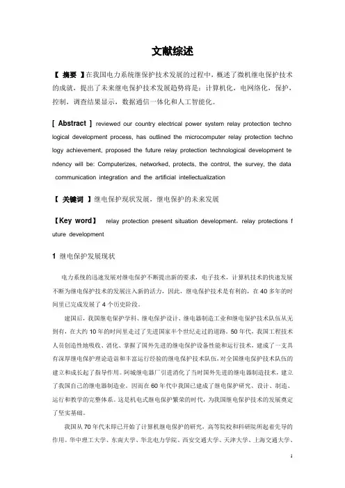
文献综述【摘要】在我国电力系统继保护技术发展的过程中,概述了微机继电保护技术的成就,提出了未来继电保护技术发展趋势将是:计算机化,电网络化,保护,控制,调查结果显示,数据通信一体化和人工智能化。
[ Abstract ]reviewed our country electrical power system relay protection techno logical development process, has outlined the microcomputer relay protection techno logy achievement, proposed the future relay protection technological development te ndency will be: Computerizes, networked, protects, the control, the survey, the data communication integration and the artificial intellectualization【关键词】继电保护现状发展,继电保护的未来发展【Key word】relay protection present situation development,relay protections f uture development1 继电保护发展现状电力系统的迅速发展对继电保护不断提出新的要求,电子技术,计算机技术的快速发展不断为继电保护技术的发展注入新的活力,因此,继电保护技术是有利的,在40多年的时间里已完成发展了4个历史阶段。
建国后,我国继电保护学科、继电保护设计、继电器制造工业和继电保护技术队伍从无到有,在大约10年的时间里走过了先进国家半个世纪走过的道路。
50年代,我国工程技术人员创造性地吸收、消化、掌握了国外先进的继电保护设备性能和运行技术,建成了一支具有深厚继电保护理论造诣和丰富运行经验的继电保护技术队伍,对全国继电保护技术队伍的建立和成长起了指导作用。
Faults on Power SystemsEach year new design of power equipment bring about increased reliability of operation. Nevertheless, equipment failures and interference by outside sources occasionally result in faults on electric power systems. On the occurrence of a fault , current an voltage conditions become abnormal, the delivery of power from the generating station to the loads may be unsatisfactory over a considerable area, and if the faulted equipment is not promptly disconnected from the remainder of the system, damage may result to other pieces of operating equipment.A faulty is the unintentional or intentional connecting together of two or more conductors which ordinarily operate with a difference of potential between them. The connection between the conductors may be by physical metallic contact or it may be through an arc. At the fault, the voltage between the two parts is reduced to zero in the case of metal-to-metal contacts, or to a very low value in case the connection is through an arc. Currents of abnormally high magnitude flow through the network to the point of fault. These short-circuit currents will usually be much greater than the designed thermal ability of the condition in the lines or machines feeding the fault . The resultant rise in temperature may cause damage by the annealing of conductors and by the charring of insulation. In the period during which the fault is permitted to exist, the voltage on the system in the near vicinity of the fault will be so low that utilization equipment will be inoperative. It is apparent that the late conditions that exist during a fault, and provide equipment properly adjusted to open the switches necessary to disconnect the faulted equipment from the remanding of the system. Ordinarily it is desirable that no other switches on the system are opened, as such behavior would result in unnecessary modification the system circuits.A distinction must be made between and an overload. An overload implies only that loads greater than the designed values have been imposed on system. Under such a circumstance the voltage at the overload point may be low, but not zero. This undervoltage condition may extend for some distance beyond the overload point into the remainder of the system. The current in the overload equipment are high and may exceed the thermal design limits. Nevertheless, such currents are substantially lower than in the case of a fault. Service frequently may be maintained, but at below-standard voltage.Overloads are rather common occurrences in homes. For example, a housewife might plug five waffle irons into the kitchen circuit during a neighborhood part. Such an overload, if permitted to continue, would cause heating of the wires from the power center and might eventually start a fire. To prevent such trouble, residential circuits are protected by fuses or circuit breakers which open quickly when currents above specified values persist. Distribution transformers are sometimes overloads as customers install more and more appliances. The continuous monitoring of distribution circuits is necessary to be certain that transformers sizes are increased as load grows.Faults of many types and causes may appear on electric power systems. Many of us in our homes have seen frayed lamp cords which permitted the two conductors of the cord to come in contact with each other. When this occurs, there is a resulting flash, and if breaker or fuse equipment functions properly, the circuit is opened.Overhead lines, for the most part, are constructed of bare conductors. There are sometimes accidentally brought together by action of wind, sleets, trees, cranes, airplanes, or damage to supporting structures. Overvoltages due to lighting or switching nay cause flashover of supporting or from conductor to conductor. Contamination on insulators sometimes results in flashover even during normal voltage conditions.The conductors of underground cables are separated from each and from ground by solid insulation, which nay be oil-impregnated paper or a plastic such polyethylene. These materials undergo somedeterioration with age, particularly if overloads on the cables have resulted in their operation at elevated temperature. Any small void present in the body of the insulating material will results in ionization of the gas contained therein, the products of which react unfavorably with the insulation. Deterioration of the insulation may result in failure of the material to retain its insulating properties, and short circuits will develop between the cable conductors. The possibility of cable failure is increased if lightening or switching produces transient voltage of abnormally high values between the conductors.Transformer failures may be the result of insulation deterioration combined with overvoltage due to lightning or switching transients. Short circuit due to insulation failure between adjacent turns of the same winding may result from suddenly applied overvoltage. Major insulation may fail, permitting arcs to be established between primary and secondary windings or between winding and grounded metal parts such as the core or tank.Generators may fail due to breakdown of the insulation between adjacent turns in the same slot, resulting in a short circuit in a single turn of the generator. Insulation breakdown may also occur between one of the winding and the grounded steel structure in which the coils are embedded. Breakdown between different windings lying in the same slot results in short-circuiting extensive section of machine.Balanced three-phase faults, like balanced three-phase loads, may be handled on a lineto-neutral basis or on an equivalent single-phase basis. Problems may be solved either in terms of volts, amperes, and ohms. The handing of faults on single-phase lines is of course identical to the method of handing three-phase faults on an equivalent single-phase basis.Faults may be classified as permanent or temporary. Permanent faults are those in which insulation failure or structure failure produces damage that makes operation of the equipment impossible and requires repairs to be made. Temporary faults are those which may be removed by deenergizing the equipment for a short period of time, short circuits on overhead lines frequently are of this nature. High winds may cause two or more conductions to swing together momentarily. During the short period of contact. An arc is formed which may continue as long as line remains energized. However, if automatic equipment can be brought into operation to service as soon as the are is extinguished. Arcs across insulators due to overvoltages from lighting or switching transients usually can be cleared by automatic circuit-breaker operation before significant structure damage occurs.Because of this characteristic of faults on lines, many companies operate following a procedure known as high-speed reclosing. On the occurrence of a fault, the line is promptly deenergized by opening the circuit breakers at each end of the line. The breakers remain open long enough for the arc to clear, and then reclose automatically. In many instances service is restored in a fraction of a second. Of course, if structure damage has occurred and the fault persists, it is necessary for the breakers to reopen and lock open.电力系统故障每年新设计的电力设备都使系统的可靠性不断提高,然而,设备的使用不当以及一些偶然遇到的外在因素均会导致系统故障的发生。
(完整版)电力系统外文英语文献资料Electric Power SystemElectrical power system refers to remove power and electric parts of the part,It includes substation, power station and distribution. The role of the power grid is connected power plants and users and with the minimum transmission and distribution network disturbance through transport power, with the highest efficiency and possibility will voltage and frequency of the power transmission to the user fixed .Grid can be divided into several levels based on the operating voltage transmission system, substructure, transmission system and distribution system, the highest level of voltage transmission system is ZhuWangJia or considered the high power grids. From the two aspects of function and operation, power can be roughly divided into two parts, the transmission system and substation. The farthest from the maximum output power and the power of the highest voltage grade usually through line to load. Secondary transmission usually refers to the transmission and distribution system is that part of the middle. If a plant is located in or near the load, it might have no power. It will be direct access to secondary transmission and distribution system. Secondary transmission system voltage grade transmission and distribution system between voltage level. Some systems only single second transmission voltage, but usually more than one. Distribution system is part of the power system and its retail service to users, commercial users and residents of some small industrial users. It is to maintain and in the correct voltage power to users responsible. In most of the system, Distribution system accounts for 35% of the total investment system President to 45%, andtotal loss of system of the half .More than 220kv voltage are usually referred to as Ultra high pressure, over 800kv called high pressure, ultra high voltage and high pressure have important advantages, For example, each route high capacity, reduce the power needed for the number of transmission. In as high voltage to transmission in order to save a conductor material seem desirable, however, must be aware that high voltage transmission can lead to transformer, switch equipment and other instruments of spending increases, so, for the voltage transmission to have certain restriction, allows it to specific circumstances in economic use. Although at present, power transmission most is through the exchange of HVDC transmission, and the growing interest in, mercury arc rectifier and brake flow pipe into the ac power generation and distribution that change for the high voltage dc transmission possible.Compared with the high-voltage dc high-voltage ac transmission has the following some advantages: (1) the communication with high energy; (2) substation of simple maintenance and communication cost is low; (3) ac voltage can easily and effectively raise or lower, it makes the power transmission and high pressure With safety voltage distribution HVDC transmission and high-voltage ac transmission has the following advantages: (1) it only need two phase conductors and ac transmission to three-phase conductors; (2) in the dc transmission impedance, no RongKang, phase shift and impact overvoltage; (3) due to the same load impedance, no dc voltage, and transfer of the transmission line voltage drop less communication lines, and for this reason dc transmission line voltage regulator has better properties; (4) in dc system withoutskin effect. Therefore, the entire section of route conductors are using; (5) for the same work, dc voltage potential stress than insulation. Therefore dc Wire need less insulation; (6) dc transmission line loss, corona to little interference lines of communication; (7) HVDC transmission without loss of dielectric, especially in cable transmission; (8) in dc system without stability and synchronization of trouble.A transmission and the second transmission lines terminated in substation or distribution substations, the substation and distribution substations, the equipment including power and instrument transformer and lightning arrester, with circuit breaker, isolating switch, capacitor set, bus and a substation control equipment, with relays for the control room of the equipment. Some of the equipment may include more transformer substations and some less, depending on their role in the operation. Some of the substation is manual and other is automatic. Power distribution system through the distribution substations. Some of them by many large capacity transformer feeders, large area to other minor power transformer capacity, only a near load control, sometimes only a doubly-fed wire feeders (single single variable substation)Now for economic concerns, three-phase three-wire type communication network is widely used, however, the power distribution, four lines using three-phase ac networks.Coal-fired power means of main power generating drive generators, if coal energy is used to produce is pushing the impeller, then generate steam force is called the fire. Use coal produces steam to promote the rotating impeller machine plant called coal-fired power plants. In the combustion process, the energy stored in the coal to heat released,then the energy can be transformed into the form within vapor. Steam into the impeller machine work transformed into electrical energy.Coal-fired power plants could fuel coal, oil and natural gas is. In coal-fired power plant, coal and coal into small pieces first through the break fast, and then put out. The coal conveyer from coal unloader point to crush, then break from coal, coal room to pile and thence to power. In most installations, according to the needs of coal is, Smash the coal storage place, no coal is through the adjustable coal to supply coal, the broken pieces of coal is according to the load changes to control needs. Through the broken into the chamber, the coal dust was in the second wind need enough air to ensure coal burning.In function, impeller machine is used to high temperature and high pressure steam energy into kinetic energy through the rotation, spin and convert electricity generator. Steam through and through a series of impeller machine parts, each of which consists of a set of stable blade, called the pipe mouth parts, even in the rotor blades of mobile Li called. In the mouth parts (channel by tube nozzle, the steam is accelerating formation) to high speed, and the fight in Li kinetic energy is transformed into the shaft. In fact, most of the steam generator is used for air is, there is spread into depression, steam turbine of low-pressure steam from the coagulation turbine, steam into the condenses into water, and finally the condensate water is to implement and circulation.In order to continuous cycle, these must be uninterrupted supply: (1) fuel; (2) the air (oxygen) to the fuel gas burning in the configuration is a must; (3) and condenser, condensed from the condensed water supply, sea and river to lake. Common coolingtower; (4) since water vapour in some places in circulation, will damage process of plenty Clean the supply.The steam power plant auxiliary system is running. For a thermal power plant, the main auxiliary system including water system, burning gas and exhaust systems, condensation system and fuel system. The main auxiliary system running in the water pump, condensation and booster pump, coal-fired power plants in the mill equipment. Other power plant auxiliary equipment including air compressors, water and cooling water system, lighting and heating systems, coal processing system. Auxiliary equipment operation is driven by motor, use some big output by mechanical drive pump and some of the impeller blades, machine drive out from the main use of water vaporimpeller machine. In coal-fired power plant auxiliary equipment, water supply pump and induced draft fan is the biggest need horsepower.Most of the auxiliary power generating unit volume increased significantly in recent years, the reason is required to reduce environment pollution equipment. Air quality control equipment, such as electrostatic precipitator, dust collection of flue gas desulfurization, often used in dust in the new coal-fired power plants, and in many already built in power plant, the natural drive or mechanical drive, fountain, cooling tower in a lake or cooling canal has been applied in coal-fired power plants and plants, where the heat release need to assist cooling system.In coal-fired power stations, some device is used to increase the thermal energy, they are (1) economizer and air preheater, they can reduce the heat loss; (2) water heater, he can increase the temperature of water into boiling water heaters; (3) they can increase and filter the thermal impeller.Coal-fired power plants usually requires a lot of coal and coal reservoirs, however the fuel system in power plant fuel handling equipment is very simple, and almost no fuel oil plants.The gas turbine power plants use gas turbine, where work is burning gas fluid. Although the gas turbine must burn more expensive oil or gas, but their low cost and time is short, and can quickly start, they are very applicable load power plant. The gas turbine burn gas can achieve 538 degrees Celsius in the condensing turbine, however, the temperature is lower, if gas turbine and condenser machine, can produce high thermal efficiency. In gas turbine turbine a combined cycle power plant. The gas through a gas turbine, steam generator heat recovery in there were used to generate vapor heat consumption. Water vapor and then through a heated turbine. Usually a steam turbine, and one to four gas turbine power plant, it must be rated output power.。


电力系统继电保护外文及翻译Power System ProtectionsThe steady-state operation of a power system is frequently disturbed by various faults on electrical equipment. To maintain the proper operation of the power system, an effective, efficient and reliable protection scheme is required. Power system components are designed to operate under normal operating conditions.However, due to any reason, say a fault, there is an abnormality, it is necessary that there should be a device which senses these abnormal conditions and if so, the element or component where such an abnormality has taken place is removed, i.e. deleted from the rest of the system as soon as possible. This is necessary because the power system component can never be designed to withstand the worst possible conditions due to the fact that this will make the whole system highly uneconomical. And therefore, if such an abnormality takes place in any element or component of the power system network, it is desirable that the affected element/component is removed from the rest of the system reliably and quickly in order to restore power in the remaining system under the normal condition as soon as possible.The protection scheme includes both the protective relays and switching circuits, i.e. circuit breakers. The protective relay which functions as a brain is a very important component. The protective relay is a sensing device, which senses the fault, determines its location and then sends command to the proper circuit breaker by closing its trip coil. The circuit breaker after getting command from the protective relay disconnects only the faulted element. this is why the protective relay must be reliable, maintainable and fast in operation.In early days, there used to be electromechanical relay of induction disk-type.However, very soon the disk was replaced by inverted cup, i.e.hollow cylinder and the new relay obtained was known as an induction cup or induction cylinder relay. This relay, which is still in use, possesses several important features such as higher speed; higher torque for a given power input an more uniform torque.However, with the advent of electronic tubes, electronic relays having distinct features were developed during 1940s. With the discovery of solid state components during 1950s, static relays with numerous advantages were developed. The use of digital computers for protective relaying purposes has been engaging the attention of research and practicing engineers since layer 1960s and 1980s. Now, the microprocessor/mini computer-based relaying scheme, because of its numerous advantages such as self –checking feature and flexibility, has been widely used in power system all over the world.The overall system protection is divided into following sections: (i)Generator protection,(ii)Transformer protection,(iii)Bus protection,(iv)Feederprotection,(v)Transmission line protection.Basic Requirements to Protective RelaysAny protection scheme, which i.e. required to safeguard the power system components against abnormal conditions such as faults, consists basically of two elements(i)Protective relay and (ii) Circuit breaker .The protective relay which is primarily the brain behind the whole scheme plays a very important role. Therefore proper care should be taken in selecting an appropriate protective relay which is reliable, efficient and fast in operation. The protective relay must satisfy the following requirements:⑴ since faults on a well designed and healthy system are normally rare, therelays are called upon to operate only occasionally. This means that therelaying scheme is normally idle and must operate whenever fault occurs. Inother words, it must be reliable.⑵ Since the reliability partly depends upon the maintenance, the relay mustbe easily maintainable.⑶ The palpation of the relay can be in two ways. One is the failure to operatein case a fault occurs an second is the relay operation when there is no fault.As a matter of fact, relay must operate if there is a fault and must notoperate if there is no fault.⑷Relaying scheme must be sensitive enough to distinguish between normaland the faulty system.Protective RelaysThe function of the protective relay is to sense the fault and energize the tripcoil of the circuit breaker. The following types of the protective relays are usedfor the apparatus such as synchronous machines, bus bar, transformer and theother apparatus and transmission line protection.(1) Over current relays,(2) Under voltage relays,(3) Under frequency relays,(4) Directional relays,(5) Thermal relays,(6) Phase sequence relays such as(i)negative sequence relays and, (ii)zerosequence relays,(7) Differential relays and percentage differential relays,(8) Distance relays such as (I)plane impedance relays,(ii)angle impedance relay,i.e. Ohm or reactance relays,(iii)angle admittance relays,i.e. Mho relaysand ,(iv)offset and restricted relays,(9)Pilot relays such as (i) wire pilot relays,(ii)carrier channel pilotrelays,(iii)microwave pilot relays. There are different types of the relayingscheme based on construction. They are:(i)electromechanicaltype,(ii)thermal relays,(iii) transduction relays,(iv)rectifier bridgerelay,(v)electronic relays,(vi)digital relaying schemes.电力系统继电保护电力系统的稳态运行经常会因各种电力设备配故障原因而被扰乱。
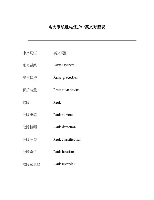
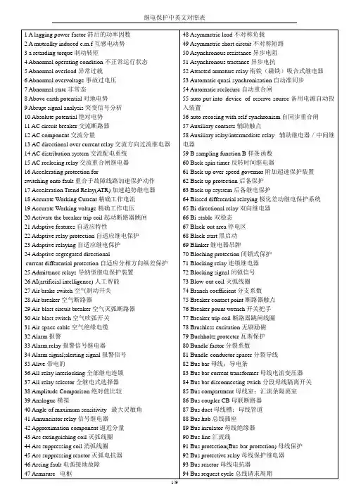
电力系统继电保护中英文对照表中文词汇英文词汇电力系统Power system继电保护Relay protection保护装置Protective device故障Fault故障电流Fault current故障检测Fault detection故障分类Fault classification故障定位Fault location故障记录器Fault recorder过电压保护Overvoltage protection过电流保护Overcurrent protection地电流保护Earth current protection短路Short circuit短路电流Short circuit current瞬时值Instantaneous value时限值Time limit value跳闸Tripping启动电流Starting current感应式电流互感器Inductive current transformer 压板式电流互感器Plate-type current transformer 合闸Closing开关刀闸Switch disconnector接地刀闸Ground disconnector电流互感器Current transformer功率互感器Power transformer电压互感器Voltage transformer电流差动保护Current differential protection 电压差动保护Voltage differential protection 闭锁Blocking重保Backup protection保护跳闸Protection tripping故障保护Fault protection过零保护Zero-crossing protection过频保护Over-frequency protection沉侵保护Inrush protection远方保护Remote protection就地保护Local protection瞬变保护Transient protection空气开关Air switch隔离开关Isolation switch封闭开关Enclosed switch电力系统自动化Power system automation 故障指示灯Fault indicator电源Power supply接线Wiring电流Current电压Voltage功率Power频率Frequency相位Phase直流Direct current交流Alternating current以上是电力系统继电保护中英文对照表,希望对您有所帮助。
毕业设计(论文) 外文翻译外文题目: Protection Relay 中文题目:继电保护学院名称:电子与信息工程学院专业:电气工程及其自动化班级:电气082继电保护摘要:继电保护非常重要,因为大部分的用户,是从分布线和分配制度以来,比任何其他部分的系统更容易受到破坏。
回顾我国电力系统继保护技术发展的过程中,概述了微机继电保护技术的成就,提出了未来继电保护技术发展趋势将是:计算机化,电网络化,保护,控制,调查结果显示,数据通信一体化和人工智能化。
关键词:继电保护,继电保护现状发展,继电保护的未来发展一、继电保护原理及现状电力系统的迅速发展对继电保护不断提出新的要求,电子技术,计算机技术的快速发展不断为继电保护技术的发展注入新的活力,因此,继电保护技术是有利的,在40多年的时间里已完成发展了4个历史阶段。
建国后,我国继电保护学科、继电保护设计、继电器制造工业和继电保护技术队伍从无到有,在大约10年的时间里走过了先进国家半个世纪走过的道路。
50年代,我国工程技术人员创造性地吸收、消化、掌握了国外先进的继电保护设备性能和运行技术,建成了一支具有深厚继电保护理论造诣和丰富运行经验的继电保护技术队伍,对全国继电保护技术队伍的建立和成长起了指导作用。
阿城继电器厂引进消化了当时国外先进的继电器制造技术,建立了我国自己的继电器制造业。
因而在60年代中我国已建成了继电保护研究、设计、制造、运行和教学的完整体系。
这是机电式继电保护繁荣的时代,为我国继电保护技术的发展奠定了坚实基础。
自50年代末,晶体管继电保护已在开始研究。
60年代中到80年代中是晶体管继电保护蓬勃发展和广泛采用的时代。
其中天津大学与南京电力自动化设备厂合作研究的500kv晶体管方向高频保护和南京电力自动化研究院研制的晶体管高频闭锁距离保护,运行于葛洲坝50 0 kv线路上,结束了500kv线路保护完全依靠从国外进口的时代。
在此期间,从70年代中,基于集成运算放大器的集成电路保护已开始研究。
Power System ProtectionsThe steady-state operation of a power system is frequently disturbed by various faults on electrical equipment. To maintain the proper operation of the power system, an effective, efficient and reliable protection scheme is required. Power system components are designed to operate under normal operating conditions.However, due to any reason, say a fault, there is an abnormality, it is necessary that there should be a device which senses these abnormal conditions and if so, the element or component where such an abnormality has taken place is removed, i.e. deleted from the rest of the system as soon as possible. This is necessary because the power system component can never be designed to withstand the worst possible conditions due to the fact that this will make the whole system highly uneconomical. And therefore, if such an abnormality takes place in any element or component of the power system network, it is desirable that the affected element/component is removed from the rest of the system reliably and quickly in order to restore power in the remaining system under the normal condition as soon as possible.The protection scheme includes both the protective relays and switching circuits, i.e. circuit breakers. The protective relay which functions as a brain is a very important component. The protective relay is a sensing device, which senses the fault, determines its location and then sends command to the proper circuit breaker by closing its trip coil. The circuit breaker after getting command from the protective relay disconnects only the faulted element. this is why the protective relay must be reliable, maintainable and fast in operation.In early days, there used to be electromechanical relay of induction disk-type.However, very soon the disk was replaced by inverted cup, i.e.hollow cylinder and the new relay obtained was known as an induction cup or induction cylinder relay. This relay, which is still in use, possesses several important features such as higher speed; higher torque for a given power input an more uniform torque.However, with the advent of electronic tubes, electronic relays having distinct features were developed during 1940s. With the discovery of solid state components during 1950s, static relays with numerous advantages were developed. The use of digital computers for protective relaying purposes has been engaging the attention of research and practicing engineers since layer 1960s and 1980s. Now, the microprocessor/mini computer-based relaying scheme, because of its numerous advantages such as self –checking feature and flexibility, has been widely used in power system all over the world.The overall system protection is divided into following sections: (i)Generator protection,(ii)Transformer protection,(iii)Bus protection,(iv)Feederprotection,(v)Transmission line protection.Basic Requirements to Protective RelaysAny protection scheme, which i.e. required to safeguard the power system components against abnormal conditions such as faults, consists basically of two elements(i)Protective relay and (ii) Circuit breaker .The protective relay which is primarily the brain behind the whole scheme plays a very important role. Therefore proper care should be taken in selecting an appropriate protective relay which is reliable, efficient and fast in operation. The protective relay must satisfy the following requirements:⑴ since faults on a well designed and healthy system are normally rare, therelays are called upon to operate only occasionally. This means that therelaying scheme is normally idle and must operate whenever fault occurs. Inother words, it must be reliable.⑵ Since the reliability partly depends upon the maintenance, the relay mustbe easily maintainable.⑶ The palpation of the relay can be in two ways. One is the failure to operatein case a fault occurs an second is the relay operation when there is no fault.As a matter of fact, relay must operate if there is a fault and must notoperate if there is no fault.⑷Relaying scheme must be sensitive enough to distinguish between normaland the faulty system.Protective RelaysThe function of the protective relay is to sense the fault and energize the tripcoil of the circuit breaker. The following types of the protective relays are usedfor the apparatus such as synchronous machines, bus bar, transformer and the other apparatus and transmission line protection.(1) Over current relays,(2) Under voltage relays,(3) Under frequency relays,(4) Directional relays,(5) Thermal relays,(6) Phase sequence relays such as(i)negative sequence relays and, (ii)zerosequence relays,(7) Differential relays and percentage differential relays,(8) Distance relays such as (I)plane impedance relays,(ii)angle impedance relay,i.e. Ohm or reactance relays,(iii)angle admittance relays,i.e. Mho relaysand ,(iv)offset and restricted relays,(9)Pilot relays such as (i) wire pilot relays,(ii)carrier channel pilotrelays,(iii)microwave pilot relays. There are different types of the relayingscheme based on construction. They are:(i)electromechanicaltype,(ii)thermal relays,(iii) transduction relays,(iv)rectifier bridgerelay,(v)electronic relays,(vi)digital relaying schemes.电力系统继电保护电力系统的稳态运行经常会因各种电力设备配故障原因而被扰乱。
Fundamentals of protection practiceThe purpose of an electrical power system is to generate and supply electrical energy to consumers. The system should be designed and managed to deliver this energy to the utilization points with both reliability and economy. As these two requirements are largely opposed, it is instructive to look at the reliability of a system and its cost and value to the consumer.One hand ,The diagram mast make sure the reliability in system design,. On the other hand, high reliability should not be pursued as an end in itself, regardless of cost, but should rather be balanced against economy,taking.Security of supply can be bettered by improving plant design, increasing the spare capacity margin and arranging alternative circuits to supply loads. Sub-division of the system into zones. each controlled by switchgear in association with protective gear. provides flexibility during normal operation and ensures a minimum of dislocation following a breakdown.The greatest threat to the security of a supply system is the short circuit,which imposes a sudden and sometimes violent change on system operation. The large current which then flows, accompanied by the localized release of a considerable quantity of energy, can cause fire at the fault location, and mechanical damage throughout the system, particularly to machine and transformer windings. Rapid isolation of the fault by the nearest switchgear will minimize the damage and disruption caused to the system.A power system represents a very large capital investment. To maximize the return on this outlay. the system must be loaded as much as possible. For this reason it is necessary not only to provide a supply of energy which is attractive to prospective users by operating the system ,but also to keep the system in full operation as far as possible continuously, so that it may give the best service to the consumer, and earn the most revenue for the supply authority. Absolute freedom from failure of the plant and system network cannot be guaran- teed. The risk of a fault occurring, however slight for each item, is multiplied by the number of such items which are closely associated in an extensive system, as any fault produces repercussions throughout the network. When the system is large, the chance of a fault occurring and the disturbance that a fault would bring are both so great that withoutequipment to remove faults the system will become, in practical terms, inoperable. The object of the system will be defeated if adequate provision for fault clearance is not made. Nor is the installation of switchgear alone sufficient; discriminative protective gear, designed according to the characteristics and requirements of the power system. must be provided to control the switchgear. A system is not properly designed and managed if it is not adequately protected.Protective gearThis is a collective term which covers all the equipment used for detecting,locating and initiating the removal of a fault from the power system. Relays are extensively used for major protective functions, but the term also covers direct-acting a.c.trips and fuses.In addition to relays the term includes all accessories such as current and voltage transformers, shunts, d.c.and a.c. wiring and any other devices relating to the protective relays.In general, the main switchgear, although fundamentally protective in its function, is excluded from the term protective gear, as are also common services, such as the station battery and any other equipment required to secure opera- tion of the circuit breaker. ReliablityThe performance of the protection applied to large power systems is frequently assessed numerically. For this purpose each system fault is classed as an incident and those which are cleared by the tripping of the correct circuit breakers and only those, are classed as 'correct'. The percentage of correct clearances can then be determined.This principle of assessment gives an accurate evaluation of the protection of the system as a whole, but it is severe in its judgement of relay performance, in that many relays are called into operation for each system fault, and all must behave correctly for a correct clearance to be recorded. On this basis, a performance of 94% is obtainable by standard techniques.Complete reliability is unlikely ever to be achieved by further improvements in construction. A very big step, however, can be taken by providing duplication of equipment or 'redundancy'. Two complete sets of equipment are provided, and arranged so that either by itself can carry out the required function. If the risk of an equipment failing is x/unit. the resultant risk, allowing for redundancy, is x2. Where x is small the resultant risk (x2) maybe negligible.It has long been the practice to apply duplicate protective systems to busbars, both being required to operate to complete a tripping operation, that is, a 'two-out-of-two' arrangement. In other cases, important circuits have been provided with duplicate main protection schemes, either being able to trip independently, that is, a 'one-out-of- two' arrangement. The former arrangement guards against unwanted operation, the latter against failure to operate.These two features can be obtained together by adopting a 'two-out-of-three' arrangement in which three basic systems are used and are interconnected so that the operation of any two will complete the tripping function. Such schemes have already been used to a limited extent and application of the principle will undoubtedly increase. Probability theory suggests that if a power network were protected throughout on this basis, a protection performance of 99.98% should be attainable. This performance figure requires that the separate protection systems be completely independent; any common factors, such as common current transformers or tripping batteries, will reduce the overall performance. SELECTIVITYProtection is arranged in zones, which should cover the power system completely, leaving no part unprotected. When a fault occurs the protection is required to select and trip only the neareat circuit breakers. This property of selective tripping is also called 'discrimination' and is achieved by two general methods:a Time graded systemsProtective systems in successive zones are arranged to operate in times which are graded through the sequence of equipments so that upon the occurrence of a fault, although a number of protective equipments respond, only those relevant to the faulty zone complete the tripping functiopn. The others make incomplete operations and then reset.b Unit systemsIt is possible to design protective systems which respond only to fault conditions lying within a clearly defined zone. This 'unit protection' or 'restricted protection' can be applied throughout a power system and, since it does not involve time grading, can be relatively fast in operation.Unit protection is usually achieved by means of a comparison of quantities at theboundaries of the zone. Certain protective systems derive their 'restricted' property from the configuration of the power system and may also be classed as unit protection. Whichever method is used, it must be kept in mind that selectivity is not merely a matter of relay design. It also depends on the correct co-ordination of current transformers and relays with a suitable choice of relay settings, taking into account the possible range of such variables as fault currents. maximum load current, system impedances and other related factors, where appropriate.STABILITYThis term, applied to protection as distinct from power networks, refers to the ability of the system to remain inert to all load conditions and faults external to the relevant zone. It is essentially a term which is applicable to unit systems; the term 'discrimination' is the equivalent expression applicable to non-unit systems.SPEEDThe function of automatic protection is to isolate faults from the power system in a very much shorter time than could be achieved manually, even with a great deal of personal supervision. The object is to safeguard continuity of supply by removing each disturbance before it leads to widespread loss of synchronism, which would necessitate the shutting down of plant.Loading the system produces phase displacements between the voltages at different points and therefore increases the probability that synchronism will be lost when the system is disturbed by a fault. The shorter the time a fault is allowed to remain in the system, the greater can be the loading of the system. Figure 1.5 shows typical relations between system loading and fault clearance times for various types of fault. It will be noted that phase faults have a more marked effect on the stability of the system than does a simple earth fault and therefore require faster clearance.SENSITIVITYSensitivity is a term frequently used when referring to the minimum operating current of a complete protective system. A protective system is said to be sensitive if the primary operating current is low.When the term is applied to an individual relay, it does not reter to a current or voltage setting but to the volt-ampere consumption at the minimum operating current.A given type of relay element can usually be wound for a wide range of setting currents; the coil will have an impedance which is inversely proportional to the square of the setting current value, so that the volt-ampere product at any setting is constant. This is the true measure of the input requirements of the relay, and so also of the sensitivity. Relay power factor has some significance in the matter of transient performance .For d.c. relays the VA input also represents power consumption, and the burden is therefore frequently quoted in watts.PRIMARY AND BACK-UP PROTECTIONThe reliability of a power system has been discussed in earlier sections. Many factors may cause protection failure and there is always some possibility of a circuit breaker failure. For this reason, it is usual to supplement primary protection with other systems to 'back-up' the operation of the main system and to minimize the possibility of failure to clear a fault from the system.Back-up protection may be obtained automatically as an inherent feature of the main protection scheme, or separately by means of additional equipment. Time graded schemes such as overcurrent or distance protection schemes are examples of those providing inherent back-up protection; the faulty section is normally isolated discriminatively by the time grading, but if the appropriate relay fails or the circuit breaker fails to trip, the next relay in the grading sequence will complete its operation and trip the associated circuit breaker, thereby interrupting the fault circuit one section further back. In this way complete back- up cover is obtained; one more section is isolated than is desirable but this is inevitable in the event of the failure of circuit breaker. Where the system interconnection is more complex, the above operation will be repeated so that all parallel infeeds are tripped. If the power system is protected mainly by unit schemes, automatic back-up protection is not obtained, and it is then normal to supplement the main protection with time graded overcurrent protection, which will provide local back-up cover if the main protective relays have failed, and will trip further back in the event of circuit breaker failure.Such back-up protection is inherently slower than the main protection and, depending on the power system con- figuration, may be less discriminative. For the most important circuits the performance may not be good enouugh, even as a back-up protection, or, in some cases, not even possible, owing to the effect of multiple infeeds. In these casesduplicate high speed protective systems may be installed. These provide excellent mutual back-up cover against failure of the protective equipment, but either no remote back-up protection against circuit breaker failure or, at best, time delayed cover.Breaker fail protection can be obtained by checkina that fault current ceases within a brief time interval from the operation of the main protection. If this does not occur, all other connections to the busbar section are interrupted, the condition being necessarily treated as a busdar fault. This provides the required back-up protection with the minimum of time delay, and confines the tripping operation to the one station, as compared with the alternative of tripping the remote ends of all the relevant circults.The extent and type of back-up protection which is applied will naturally be related to the failure risks and relative economic importance of the system. For distribution systems where fault clearance times are not critical, time delayed remote back-up protection is adequate but for EHV systems, where system stability is at risk unless a fault is cleared quickly, local back-up, as described above, should be chosen.Ideal back-up protection would be completely indepen_ dent of the main protection. Current transformers, voltage transformers, auxiliary tripping relays, trip coils and d.c. supplies would be duplicated. This ideal is rarely attained in practice. The following compromises are typical:a. Separate current transformers (cores and secondary windings only) are used for each protective system, as this involves little extra cost or accommodation compared with the use of common current transformers which would have to be larger because of the combined burden.b. Common voltage transformers are used because duplication would involve a considerable increase in cost, because of the voltage transformers themselves, and also because of the increased accommodation which would have to be provided. Since security of the VT output is vital, it is desirable that the supply to each protection should be separately fused and also continuously supervised by a relay which wil1 give an alarm on failure of the supply and, where appropriate, prevent an unwanted operation of the protection.c. Trip supplies to the two protections should be separately fused. Duplication of tripping batteries and of tripplng coils on circuit breakers is sometimes provided. Trip circuitsshould be continuously supervised.d. It is desirable that the main and back-up protections (or duplicate main protections) should operate on different princlples, so that unusual events that may cause failure of the one will be less likely to affect the other./viewforum.php?f=20继电保护原理发电并将电力供应给用户这就是电力系统的作用。
1 Directional protection方向保护2 Distance protection距离保护3 Over current protection过流保护4 Pilot protection高频保护5 Differential protection差动保护6 Rotor earth-fault protection 转子接地保护7 Stator earth-fault protection 定子接地保护8 Over fluxing protection过励磁保护9 Back-up protection后备保护11 Sequential tripping顺序跳闸12 Start up/Pick up起动13 Breaker断路器14 Disconnecting switch隔离开关15 Current transformer电流互感器16 Potential transformer电压互感器17 Dead zone/Blind spot死区18 Vibration/Oscillation振荡19 Reliability可靠性20 Sensitivity灵敏性21 Speed速动性22 Selectivity选择性23 Step-type distance relay分段距离继电器24 Time delay延时25 Escapement/interlock/blocking 闭锁26 Incorrect tripping误动27 Phase to phase fault相间故障28 Earth fault接地故障29 Through- fault穿越故障30 Permanent fault永久性故障31 Temporary fault瞬时性故障32 Overload过负荷34 Contact multiplying relay触点多路式继电器35 Timer relay时间继电器40 Ground fault relay接地故障继电器41 Recloser重合闸42 Zero-sequence protection零序保护43 Soft strap软压板44 Hard strap硬压板45 High resistance高阻46 Second harmonic escapement 二次谐波制动47 CT line-breakCT断线48 PT line-breakPT断线49 Secondary circuit二次回路50 AC circuit breaker交流开关电路51 AC directional over current relay 交流方向过流继电器52 Breaker point wrench开关把手53 Breaker trip coil断路器跳闸线圈54 Bus bar母线; 导电条55 Bus bar current transformer母线电流变压器56Bus bar disconnecting switch分段母线隔离开关57Bus compartment母线室; 汇流条隔离室58Bus duct母线槽; 母线管道59Bus hub总线插座60Bus line汇流线61Bus insulator母线绝缘器62Bus request cycle总线请求周期63Bus reactor母线电抗器64Bus protection母线保护65Bus rings集电环66Bus rod汇流母线67Bus section reactor分段电抗器68Bus structure母线支架; 总线结构69Bus tie switch母线联络开关70Bus-bar chamber母线箱71Bus-bar fault母线故障72Bus-bar insulator母线绝缘子73Busbar sectionalizing switch 母线分段开关74Current attenuation电流衰减75Current actuated leakage protector电流起动型漏电保护器76Current balance type current differential relay电流平衡式差动电流继电器;差动平衡式电流继电器77Current changer换流器78Current compensational ground distance relay电流补偿式接地远距继电器79Current consumption电流消耗80Coil adjuster线圈调节器81Coil curl线圈82Coil current线圈电流83Coil end leakage reactance线圈端漏电抗84Coil inductance线圈电感85Current transformer phase angle电流互感器相角86Distance relay; impedance relay阻抗继电器87Power rheostat电力变阻器88Electrically operated valve电动阀门89Electrical governing system电力调速系统90Field application relay励磁继电器; 激励继电器91High tension electrical porcelain insulator 高压电瓷绝缘子92Option board任选板; 选配电路板; 选择板93Oscillator coil振荡线圈94Over-V oltage relay过压继电器95Power factor relay功率因素继电器96Protection against overpressure超压防护97Protection against unsymmetrical load 不对称负载保护装置98Protection device保护设备; 防护设备99Protection reactor保护电抗器100Protection screen保护屏101Protection switch保护开关102Insulator cap绝缘子帽; 绝缘子帽103Insulator chain绝缘子串; 绝缘子串104Insulator arc-over绝缘子闪络; 绝缘子闪络105Insulator arcing horn绝缘子角形避雷器; 绝缘子角形避雷器106Insulator bracket绝缘子托架; 绝缘子托架107Impedance compensator阻抗补偿器108 Resistance grounded neutral system 中心点电阻接地方式109 Reactance bond电抗耦合; 接合扼流圈110 Reactance of armature reaction电枢反应电抗111 Under-Voltage relay欠压继电器112 V oltage differential relay电压差动继电器114 Relay must-operate value继电器保证启动值115 Relay act trip继电器操作跳闸116 Relay overrun继电器超限运行117 Longitudinal differential protection纵联差动保护118 Phase-angle of voltage transformer电压互感器的相角差119 Zero-sequence current/residual current 零序电流120 Residual current relay零序电流继电器121 Bus bar protection/bus protection母线保护122 Breaker contact point断路器触点123 Cut-off push断路器按钮124 Gaseous shield瓦斯保护装置125 Neutral-point earthing中性点接地126 Internal fault内部故障127 Auxiliary contacts辅助触点128 Neutral auto-transformer中性点接地自耦变压器129 Fuse box/fusible cutout熔断器130 Pulse relay/surge relay冲击继电器旅长2005131 Auxiliary relay/intermediate relay中间继电器132 Common-mode voltage共模电压133 Impedance mismatch阻抗失配134 Intermittent fillet weld间断角缝焊接135 Loss of synchronism protection失步保护136 Closing coil合闸线圈137 Electro polarized relay极化继电器138 Power direction relay功率方向继电器139 Direct-to-ground capacity对地电容140 Shunt running潜动141 Trip/opening跳闸142 Trip switch跳闸开关143 Receiver machine收信机144 High-frequency direction finder 高频测向器145 Capacity charge电容充电146 time over-current时限过电流148 Surge guard冲击防护149 Oscillatory surge振荡冲击150 Fail safe interlock五防装置151 Differential motion差动152 Capacitive current电容电流154 Time delay延时156 Normal inverse反时限157 Definite time定时限158 Multi-zone relay分段限时继电器159 Fail-safe unit五防161 Unbalance current不平衡电流162 Blocking autorecloser 闭锁重合闸163 Primary protection主保护164 Tap分接头165 YC (telemetering)遥测167 Fault clearing time故障切除时间168 Critical clearing time 极限切除时间169 Switch station开关站170 Traveling wave行波171 Protection feature保护特性172 Fault phase selector故障选线元件173 Fault type故障类型174 Inrush励磁涌流175 Ratio restrain比率制动176 Laplace and Fourier transforms 拉氏和傅利叶变换177 Short circuit calculations短路计算178 Load flow calculations潮流计算179 Oscillatory reactivity perturbation 振荡反应性扰动180 Quasi-steady state准稳态181 Automatic quasi-synchronization 自动准同步182 Protective relaying equipment继电保护装置183 AC directional overcurrent relay 交流方向过流继电器184 AC reclosing relay交流重合闸继电器185 Annunciator relay信号继电器188 Carrier or pilot-wire receiver relay载波或导引线接受继电器189 Current-limiting relay限流继电器190 Definite time relay定时限继电器192 Lockout relay闭锁继电器;保持继电器;出口继电器193 Micro-processor based protective relay 微机继电保护194 V oltage -controlled overcurrent relay 电压控制过电流继电器196 Fault diagnosis故障诊断197 Back-up protection后备保护198 Overhead line架空线199 High voltage line高压线路200 Underground cable埋地电缆201 Circuit breaker断路器202 Brushless excitation无刷励磁203 Interlock闭锁204 Trigger触发器205 Winding-to-winding insulation绕组间的绝缘206 Porcelain insulator瓷绝缘子207 Tie line联络线208 Leased line租用线路209 Private line专用线路211 Remote Terminal Unit远程终端设备212 Economic dispatch system经济调度系统213 State estimation状态估计214 Trip by local protection保护跳闸215 Close by local protection保护合闸216 Operational (internal) overvoltage 操作(内部)过电压217 Sampling and holding采样保持218 Synchronized sampling采样同步219 Manipulation操作220 Measuring/Metering unit测量元件221 Locus of measured impedance测量阻抗轨迹222 Differential mode interference差模干扰223 Output (executive) organ出口(执行)元件224 Overcurrent relay with undervoltage supervision低电压起动的过电流保护225 Low impedance busbar protection低阻抗母线保护回复2帖旅长2005228 Half-cycle integral algorithm半周积分算法230 Coordination of relay settings保护的整定配合231 Reach (setting) of protection保护范围(定值)232 Coordination time interval保护配合时间阶段233 Percentage differential relay比率差动继电器234 Electromagnetic relay电磁型继电器236 Instantaneous undervoltage protection with current supervision 电流闭锁的电压速断保护237 Operating equation (criterion)动作方程(判据)238 Operating characteristic动作特性239Harmonic restraining谐波制动241Segregated current differential protection分相电流差动保护242Branch coefficient分支系数243Power line carrier channel (PLC)高频通道245High speed signal acquisition system高速数字信号采集系统246Busbar protection with fixed circuit connection 固定联结式母线保护247Fault recorder故障录波器248Fault phase selection故障选相249Optoelectronic coupler光电耦合器件251Compensating voltage补偿电压252Polarized voltage极化电压253Memory circuit记忆回路254Unblocking signal解除闭锁信号255Power system splitting and reclosing解列重合闸256Connection with 90 degree90度接线257Insulation supervision device绝缘监视258Inrush exciting current of transformer励磁涌流259Two star connection scheme两相星形接线方式260Zero mode component of traveling wave 零模行波261Inverse phase sequence protection逆相序保护262Offset impedance relay偏移特性阻抗继电器263Frequency response频率响应264Activate the breaker trip coil起动断路器跳闸266Permissive under reaching transfer trip scheme 欠范围允许跳闸式267Slight (severe) gas protection轻(重)瓦斯保护268Man-machine interface人机对话接口270Three phase one shot reclosure三相一次重合闸271Out-of-step失步272Accelerating protection for switching onto fault 重合于故障线路加速保护动作275Abrupt signal analysis突变信号分析276Out flowing current外汲电流277False tripping误动279Turn to turn fault,inter turn faults匝间短路280Relay based on incremental quantity增量(突变量)继电器281Vacuum circuit breaker真空开关282Power swing (out of step) blocking振荡(失步)闭锁284Successive approximation type A/D逐次逼进式A/D285Infeed current助增电流286Self reset自动复归287Adaptive segregated directional current differential protection 自适应分相方向纵差保护288Adaptive relay protection自适应继电保护289Pilot protection纵联保护291Angle of maximum sensitivity 最大灵敏角292Out of service退出运行294Waveform波形295Outlet出口296Electromechanical机电的297Magnitude of current电流幅值299Traveling wave signal行波信号300Measurement signal测量信号301Traveling wave relay行波继电器302Transmission line malfunction 输电线路异常运行303Subsystem子系统304Positive sequence impedance 正序阻抗305Negative sequence impedance 负序阻抗306Zero sequence impedance零序阻抗307Digital signal processor数字信号处理器308Frequency sensing频率测量309Cable relay电缆继电器310Under power protection低功率保护311Under voltage protection低电压保护312Transient analysis暂态分析313V oltage sensor电压传感器314Zero-sequence protection零序保护315Zero sequence current transducer 零序电流互感器316Shunt旁路,并联317Series串联,级数318Parallel并联319Saturation饱和320Free-standing独立的,无需支撑物的321Troidal环形的,曲面,螺旋管形322Bushing套管323Magnetizing磁化324Dropout current回动电流325Reactor grounded neutral system 中性点电抗接地系统326Grounding apparatus接地装置327Dual bus双总线328Thyristor晶闸管329Spark gap火花隙330Damping circuit阻尼电路331Discharge放电332Platform平台333Grading等级334Line trap线路陷波器335Field test实地试验337Off-position“断开”位置,“开路”位置338Power-angle功角339Power-angle curve功角特性曲线340Torque-angle转矩角341Symmetrical components 对称分量342Constant常量,恒定343Coupler耦合器345Concussion震动348Filter滤波器349Analogue模拟350Insulator绝缘子351Switch cabinet开关柜352Rated burden\load额定负载353Primary一次侧的354Remote-control apparatus 远距离控制设备355Capacitance电容356Capacitor电容器357Reactance电抗358Inductor电感359Internal resistance内阻360Blow-out coil消弧线圈361Bundle-conductor spacer 分裂导线362Bundle factor分裂系数363Electromotive force电动势364V olt-amphere characteristic伏安特性365Outgoing line引出线366electrolyte电解质368Load characteristic负载特性369Self-induction自感370Mutual-induction互感371Induction coefficient感应系数372Inductance couping电感耦合373Time-invariant时不变的回复3帖4旅长2005端电压375Non-linear characteristics 非线性特性376External characteristics 外特性378Harmonic current正弦电流379Pole-pairs极对数380Quadrature正交381Angular velocity角频率382Magnetic induction磁感应强度385Armature电枢386Peak value(交变量的)最大值387A mutually induced e.m.f互感电动势The applied voltage外施电压389Zero-power-factor零功率因数390The no-load power factor 空载功率因数391Sinusoidal variations正弦变量392A lagging power factor 滞后的功率因数393Equivalent circuit等值电路394Capacitance effect电容效应395Direct axis直轴396Quadrature axis交轴398Concentrated coil集中绕组399Magnetization curve磁化曲线Residual magnetism剩磁401Rated armature current 额定电枢电流402Series excited串励403Self excited自励404Shunt excited并励405spottily excited他励407 Electromagnetic torque 电磁转矩408a retarding torque制动转矩409Rectangular wave矩形波410Synchronous speed同步转速411 Electromagnetic brake 电磁制动synchronous reactance同步电抗413synchronous condenser同步调相机414Load shedding甩负荷415Black-start黑启动417Distribution feeder配电馈线418Commissioning投运419Reactive power compensation 无功补偿器420Continuous rating连续运行的额定值421AI (artificial intelligence)人工智能422Network topology网络拓补424Configuration control组态控制Topological information拓补信息426Black-out area停电区428Adaptive relaying自适应继电保护429Adaptive features自适应特性430Phase comparison relays相位比较继电器431Directional contact方向触点432Protective gap保护间隙433Protective earthing保护接地434Protective earthing; outer insulation 保护绝缘435Protection switch保护开关436Protective cap保护帽Protective panel保护屏柜439Protection device保护设备440Protective casing保护外壳441Catch net; protecting net保护网442Protection system保护系统443Protective link保护线路444Protective ground保护性接地445Protective cover; Protective housing 保护罩446Protection device; Protective gear 保护装置447Protective transformer保护变压器448Alarm relay报警信号继电器Alarm signal;alerting signal报警信号450Admittance relays导纳型继电保护装置451Low-voltage protection低压保护452Under-voltage release低电压跳闸453Under-voltage trip低电压自动跳闸454Under-run低负荷运行455Under-power protection低功率保护456Under-power relay低功率继电器457Under-frequency protection低频保护458Low-frequency high-voltage test 低频高压实验459Low-voltage relay低压继电器Low-voltage release relay 低压释放继电器461Under-frequency protection 低周波保护463Under-impedance relay低阻抗继电器465Conductance relay电导继电器466Motor-field failure relay电动机磁场故障继电器467Dynamoelectric relay电动式继电器468Electric reset relay电复位继电器469Power-transformer relay电力传输继电器471Power system oscillation 电力系统振荡472Electric interlock relay连锁继电器473Current overload电流过载Self-polarizing relay电流极化继电器475Current-balance relay 电流平衡式继电器476Circuit control relay电路控制继电器479Capacitance relay电容继电器480Capacity ground电容接地481V oltage balance relay电压平衡继电器482Circuit control relay电路控制继电器483V oltage responsive relay 电压响应继电器484V oltage selection relay 电压选择继电器485Power failure电源故障486Power-transfer relay电源切换继电器vacuum-tube relay电子管继电器488Ohm relay电阻继电器489Timing relay; timed relay定时继电器490Time pulse relay定时脉冲继电器492Directional over-current relay方向过流继电器493Directional over-current protection 方向过流保护494Directional distance relay方向距离继电器495Directional pilot relaying方向纵联继电保护497Cut-off relay断路继电器498Circuit breaker failure protection 断路器故障保护装置500Open-phase relay断相继电器Earth-leakage protection对地漏电保护502Multiple-reclosing breaker多次重合闸断路器503Multi-ended circuit protection多端线路保护506Multiple earth多重接地507Two-position relay二位置继电器508Generator protection发电机保护509Generator cutout relay发电机断路继电器510Generator protection for negative sequence current 发电机负序电流保护511Transmitting relay发送继电器512Back-spin timer反转时间继电器513Auxiliary relay辅助继电器Negative phase relay负相位继电器515Negative-phase sequence impendence 负相序继电器516Under-load relay负载不足继电器517Back-up over-speed governor附加超速保护装置518Induction cup relay感应杯式继电器520Induction type relay感应式继电器521Induction disc relay感应圆盘式继电器522High sensitive relay高灵敏度继电器回复4帖5旅长2005523High-speed impedance relay 高速阻抗继电器524High-voltage relay高压继电器525Power relay功率继电器527Transition impedance过渡阻抗528Thermal protection过热保护529Temperature limiting relay过热继电器530Overload relay过载继电器531Overload trip过载跳闸532Thermostat relay恒温继电器533Closing relay合闸继电器534Transverse differential protection 横差保护535Transfer of auxiliary supply后备电源切换536Back-up system后备继电保护Delay-action relay缓动继电器538Slow-to release relay缓放继电器539Converter relay换流器继电器540Electromechanical relay机电继电器541Biased differential relaying极化差动继电保护系统542Discontinuous relay鉴别继电器543Transistor relay晶体管继电器544Crystal can relay晶体密闭继电器545Static relay静电继电器546Fast-operate slow-release relay 快动缓释继电器547Fast-release relay快释放继电器Excitation-loss relay失磁继电器553Two-phase short circuit fault 两相短路故障554Two-phase grounding fault 两相接地短路故障556Sensitive polarized relay灵敏极化继电器558Sensitive relay灵敏继电器560Abnormal overload异常过载561Abnormal overvoltage事故过电压562Above earth potential对地电势563Absolute potential绝对电势564AC circuit breaker交流断路器565AC component交流分量AC distribution system 交流配电系统567Air-blast circuit breaker 空气灭弧断路器568Air-blast switch空气吹弧开关569Air brake switch空气制动开关571Air breaker空气断路器572Air-space cable空气绝缘电缆573Alive带电的574All-relay interlocking 全部继电连锁575All-relay selector全继电式选择器578Arc extinguishing coil 灭弧线圈579Arc suppressing reactor 灭弧电抗器Asymmetric load不对称负载581Asymmetric short circuit 不对称短路582Asynchronous reactance 异步电抗583Asynchronous resistance 异步电阻584Biased differential relaying 极化差动继电保护系统585Bi-directional relay双向继电器586Blinker继电器吊牌587Blocking relay连锁继电器589Blowout coil灭弧线圈590Bus hub总线插座591Bus protective relay母线保护继电器Bus section breaker 母线分段断路器593Bus terminal fault母线终端故障594Bus separation母线分离595Bus tie circuit breaker 母线联络继电器596Bypass旁路597Coil factor线圈系数598Compound relay复合电路599Continuous load持续负载600Counting relay计数继电器602Cut-off of supply停止供电603Cut-out relay短路继电器Dash current冲击电流605Data medium数据载体606Data processing数据处理607Data transmission数据传输608Emergency service事故运行609Emergency standby 事故备用611Extinction coil消弧线圈612Extinguishing voltage 消弧线圈613Extra high voltage超高压614Fault line故障线615Fault location故障定位Feedback反馈617Feeder馈电线618Interlock连锁619Intermittent fault间歇故障620Interrupting time断路时间621Negative direction反方向622No-load release无跳闸623Off-peak非峰值的624Operating load运行负载625Orthogonal正交的626Rated primary voltage 一次额定电压Rated secondary volage 二次额定电压628Remote controlled遥控的629Reserve bus备用母线630Rotor转子631Sectionalizer分段断路器632Self-energizing自激的633Sequential tripping顺序跳闸637Surge voltage冲击电压638Sustained overload持续过电压639Symmetrical对称的640Fault component故障分量Wavelet transform小波变换642Object-oriented面向对象643Faults recorder故障录波644Setting calculation整定计算645Topology analysis拓扑分析646Expert system专家系统647Security安全性651Load schedule according to frequency change 按周波减载653Semiconductor, semiconductor diode, transistor 半导体、半导体二级管、三极管654Semi-orthogonal wavelet半正交小波656Saturation, saturation detection, saturation curve 饱和,饱和检测,饱和曲线Relay location保护安装处658Coordination of relay settings保护的整定配合659Coordination time interval保护配合时间阶段660Relay system configuration保护配置661Redundancy of relaying system保护配置的冗余度663Protection devices, protection equipment保护装置664Starting current and returning current of protection device 保护装置的起动电流和返回电流665Alarm报警666Approximation component逼近分量668B sampling functionB样条函数670Transformation matrix变换矩阵。
继电保护外文英语参考文献继电保护外文英语参考文献文章类型:参考文献参考文献格式本文是一篇参考文献,对于很多研究继电保护这一专业的学生们来说,参考文献的选择尤其重要,参考文献主要考察的就是同学们对这行业的`研究水平以及掌握的知识范围,现为方便广大此专业的学生们,今统计整理了部分最新的继电保护的英语参考文献,希望可以帮助到大家。
[1]Abhishek Khanna. Analysis of High Impedance Protection Considering CT-Transients and Air Gapped CTs with Setting Recommendations and a New Fast Acting Algorithm for High Impedance Numerical Relays[J]. International Journal of Emerging Electric Power Systems,2011,12(1):.[2]Mojtaba Khederzadeh. Mechanical Protection of Induction Motors by Off-the-Shelf Electrical Protective Relays[J]. International Journal of Emerging Electric Power Systems,2011,12(2):.[3]El Sayed M. Tag Eldin. A Novel Approach for Classifying Transient Phenomena in Power Transformers[J]. International Journal of Emerging Electric Power Systems,2011,1(2):.[4]J. Havelka,R. Malari?,K. Frlan. Staged-Fault Testing of Distance Protection Relay Settings[J]. Measurement Science Review,2012,12(3):.[5]Xiong Haijun,Zhang Qi. A New Method for Setting Calculation Sequence of Directional Relay Protection in Multi-Loop Networks[J]. International Journal of Emerging Electric Power Systems,2016,17(4):.[6]Si Tuyou,Wu Jiekang,Yuan Weideng,Du Anan. Power supply risk assessment method for relay protection system faults[J]. Archives of Electrical Engineering,2016,65(4):.[7]Elmer Sorrentino. Analysis of overtravel in induction disc overcurrent relays[J]. Electric Power Systems Research,2016,:.[8]Stanislav Misak,Jindrich Stuchly,Jakub Vramba,TomasVantuch,David Seidl. A novel approach to adaptive active relay protection system in single phase AC coupling Off-Grid systems[J]. Electric Power Systems Research,2016,131:.[9]Rahul Dubey,S.R. Samantaray,B.K. Panigrahi. Data-mining model based adaptive protection scheme to enhance distance relay performance during power swing[J]. International Journal of Electrical Power and Energy Systems,2016,:.[10]Manoj Thakur,Anand Kumar. Optimal coordination of directional over current relays using a modified real coded genetic algorithm: A comparative study[J]. International Journal of Electrical Power and Energy Systems,2016,:.[11]Miodrag Forcan,Zoran Stojanovi?. An algorithm for sensitive directional transverse differential protection with no voltage inputs[J]. Electric Power Systems Research,2016,:.[12]Oleg Sivov,Hany Abdelsalam,Elham Makram. Adaptive setting of distance relay for MOV-protected series compensated line considering wind power[J]. Electric Power Systems Research,2016,:.[13]S.A. Ahmadi,H. Karami,M.J. Sanjari,H. Tarimoradi,G.B. Gharehpetian. Application of Hyper-Spherical Search Algorithm for Optimal Coordination of Overcurrent Relays Considering Different Relays Characteristics[J]. International Journal of Electrical Power and Energy Systems,2016,:.[14]Ahmed R. Adly,Ragab A. El Sehiemy,Almoataz Y. Abdelaziz. A negative sequence superimposed pilot protection technique during single pole tripping[J]. Electric Power Systems Research,2016,:.[15]L.A. Trujillo Guajardo. Prony filter vs conventional filters for distance protection relays: An evaluation[J]. Electric Power Systems Research,2016,:.[16]Zohaib Akhtar,Muhammad Asghar Saqib. Microgrids formed by renewable energy integration into power grids pose electrical protection challenges[J]. Renewable Energy,2016,:.[17]A.M. Ibrahim,W. Elkhatam,M. Mesallamy,H.A. Talaat. Adaptive Protection Coordination Scheme For Distribution Network with Distributed Generation using ABC[J]. Journal of Electrical Systems and Information Technology,2015,:.[18]Ricardo C. Santos,Simon Le Blond,Denis V. Coury,Raj K. Aggarwal.A novel and comprehensive single terminal ANN based decision support for relaying of VSC based HVDC links[J]. Electric Power Systems Research,2016,:.[19]Meng Yen Shih,Arturo Conde Enríquez,Tsun-Yu Hsiao,Luis Mart ín Torres Trevi?o. Enhanced differential evolution algorithm for coordination of directional overcurrent relays[J]. Electric Power Systems Research,2016,:.[20]Fernando B. Bottura,Wellington M.S. Bernardes,Mário Oleskovicz,Eduardo N. Asada. Setting Directional Overcurrent Protection Parameters using Hybrid GA Optimizer[J]. Electric Power Systems Research,2016,:.[21]Mazen Abdel-Salam,Rashad Kamel,Khairy Sayed,Mohsen Khalaf. Design and implementation of a multifunction DSP-based-numericalrelay[J]. Electric Power Systems Research,2017,143:.[22]Elmer Sorrentino. Behavior of induction disc overcurrent relays as a function of the frequency[J]. Electric Power SystemsResearch,2016,:.[23]Emilio C. Piesciorovsky,Noel N. Schulz. Comparison ofNon-Real-Time and Real-Time Simulators with Relays In-The-Loop for Adaptive Overcurrent Protection[J]. Electric Power Systems Research,2016,:.[24]Akbar Sharafi,Majid Sanaye-Pasand,Farrokh Aminifar. Transmission System Wide-area Back-up Protection using Current Phasor Measurements[J]. International Journal of Electrical Power and Energy Systems,2017,:.[25]Min Zhu,Wei Dong Liu,Wen Song Hu. Application of Fuzzy Neural Network in Relay Protection[J]. Advanced Materials Research,2011,1100(181):.[26]Wei Kang,Xing Chen,Jian Ting Gui,He Zhang,Li Xia Zhang. Research on Microcomputer Relay Protection Anti-Interference of 500kV Transmission Line in MATLAB[J]. Advanced Materials Research,2011,1158(204):.[27]Wei Ming Guo,Gan Qing Zuo,Rui Lin. The Analysis of theOpto-Couplers Relay Malfunctions in HVDC Control and Protection and the Improvements of the Trip Circuits[J]. Advanced MaterialsResearch,2012,1478(354):.[28]Shi Qi Liu,Huan Wang,Xiao Ming Li,Dong Xu Zhou. The Research on High-Voltage Transmission Line Relay Protection Setting Related to OLTC Anti-Icing[J]. Advanced Materials Research,2012,1518(383):.[29]Xiao Ming Li,Sha Li,Peng Lu,Shu Qiong Liu. The Study on Configuration and Setting of Relay Protection when Distributed Generation Accesses to Distribution Network[J]. Advanced MaterialsResearch,2012,1566(433):.[30]Shi En He,Xin Zhou Dong,Zhi Qian Bo,Jia Le Suo Nan. The Relay Protection Scheme for Distribution Network with Distributed Generations[J]. Advanced Materials Research,2012,1566(433):.[31]Jing Jing Zhang. Research and Summary on Reliability of Relay Protection System[J]. Advanced Materials Research,2012,1566(433):.[32]Li Kai Liang,Yu Yin Zhang,Xiao Cong Zhang. Research on Programmable Logical Relay Protection[J]. Applied Mechanics and Materials,2012,2034(229):.[33]Pei Ding,Fei Guo,Xu Tao Wu,Xiu Guang Li,Zhen Hua Yan,Zhi Guo Hao. New Development in Relay Protection for Smart Grid – Protection Function Development[J]. Applied Mechanics and Materials,2013,2279(291):.[34]Xu Cen,Shu Ming Liu,Qiong Lin Li,Shun Tao. Influence of Harmonic on the Protections of Capacitor Bank[J]. Applied Mechanics and Materials,2013,2279(291):.[35]Yu Tian Zhou,Yun Wu,Tong Zuo. Research on Decision Support System of Relay Protection Equipment Status Evaluation Based on Mechanical Overhaul[J]. Applied Mechanics and Materials,2013,2549(345):.[36]Jian Xu,Xin Yao. Research and Improvement of Fourier Algorithm in the Microcomputer Relay Protection[J]. Applied Mechanics and Materials,2013,2560(347):.[37]Zong Jiang Mu,Yan Xu,Shao Bo Yan. Risk Assessment of Relay Protection Setting Value in Power Plant[J]. Applied Mechanics and Materials,2013,2594(373):.[38]Zong Jiang Mu,Yan Xu,Xing Dong Qiu,Jin Jie Wang. On-Line Verification of Relay Protection Setting Based on Transmission Contribution Degree[J]. Applied Mechanics and Materials,2013,2594(373):.[39]Huan Ren,Yan Xu,Qing Jie Zhou. Research on Condition Evaluation Method of Relay Protection Based on Reliability Indices[J]. Applied Mechanics and Materials,2013,2594(373):.[40]Lei Dong,Wei Di Li,Wen Ping Zhou,Tian Jiao Pu. Relay Protection Security Analysis of Jiuan Substation under Complex Power Transmission Environment[J]. Applied Mechanics and Materials,2013,2601(385):.[41]Pan Zhang,Yan Xia Zhang,Wen Bo Xuan,Hong Yuan Zhang,Bin Bn Tian. Study on Simulation System of Relay Protection for Smart Substation[J]. Applied Mechanics and Materials,2013,2601(385):.[42]Zhi Feng Peng,Ming Yu Yang,Qing Jie Zhou,Cheng Yong Yuan. Analysis about Random Failure Indicator for Relay Protection[J]. Applied Mechanics and Materials,2013,2635(391):.[43]Rui Li,Shu Yong Song,Zhen Guo Ma,Zi Ming Kou. Design of Setting Management System of Relay Protection to Anti-Grade Trip in Coal Mine Based on Serial Communication[J]. Applied Mechanics andMaterials,2013,2701(415):.[44]Vinay Barhate. Generating Various Inverse Time over Current Numerical Relays Using Microcontroller for Power System Protection[J]. Applied Mechanics and Materials,2013,2701(415):.[45]Qian Rui,Su Qin Qian. Relay Protection Based on Multi-Agent System[J]. Advanced Materials Research,2013,2542(760):.[46]Rui Li,Shu Yong Song,Hui Ping Zheng,Zhen Guo Ma,Hui Yong Li,Tong Yu Zhang. Design on Synchronize Debugging Device for Extra High Voltage Transmission Line Longitudinal Protection[J]. Advanced Materials Research,2013,2694(805):.[47]Xue Song Zhou,Chun Ji,You Jie Ma. Review of STATCOM Effects on Relay Protection of Power System[J]. Advanced MaterialsResearch,2013,2690(811):.[48]Jian Ping Jia. The System Design and Simulation Research of Low Voltage Lockout over Current Protection about Transmission Line[J]. Advanced Materials Research,2013,2731(823):.[49]Tao Wang,Gui Hua Lin,Dong Han. Research of Single-Device Test Based on Relay Protection Simulation and Training System[J]. Applied Mechanics and Materials,2014,2948(496):.[50]Hui Sheng Gao,Hui Fang Wang. Searching Path for Delay Protection Services of Fiber Channel Based on Security and Risk Equalization[J]. Applied Mechanics and Materials,2014,2948(496):.[51]Xin Chao Wang,Chen Xin Yang. A Study on DG Control Strategy and Grid Protection[J]. Applied Mechanics and Materials,2014,3012(521):.[52]Yong Zhang. Study on Relay Protection Technology in Power System[J]. Applied Mechanics and Materials,2014,3012(521):.[53]Nan Nan Gao,Lin Niu,Ying Pei,Hong Bo Li,Jie Zhan. Design and Application of Analysis Software for Relay Protection Action Based on PAS[J]. Applied Mechanics and Materials,2014,3082(543):.[54]Hao Ran Xue,Bin Li,Kun Ji,Zhi Qiang Wang,Xiao Jun Kong. The Optimization Methods Based on Big Data Technologies of Power System Protection[J]. Advanced Materials Research,2014,3135(918):.[55]Peng Fei Shi,Yu Jiong Gu,Wei Lin Zhang,Kun Yang. Protection of the Island Microgrid Based on Ocean Energy[J]. Advanced Materials Research,2014,3249(953):.[56]Nian Fang,Xian Shan Li,Hao Xu,Yu Long Du. Relay Protection Setting Calculation and Analysis of Auxiliary Power System for Hydropower Plants[J]. Applied Mechanics and Materials,2014,3296(574):.[57]Fen Fen Chen,Shi Wu Xiao. Micro-Grid Fault Transient Characteristics and Relay Protection[J]. Advanced Materials Research,2014,3294(986):.[58]Peng Fei Hu,Yu Xiang Yuan,Zhi Juan Qu,Xue Ping Jiang. System on Chip Design for Multi-Principle of Relay Protection in the FPGA[J]. Applied Mechanics and Materials,2014,3590(668):.[59]Gui Hua Lin,Yu Ying Wang,Tao Wang. Research on Bus Coupler Charging Protection Problem[J]. Applied Mechanics andMaterials,2014,3546(672):.[60]Zi Nan Liu,Shi Wu Xiao,Shan Jiang. Research on Evaluation Method of Relay Protection Action Based on Fault Information[J]. Advanced Materials Research,2014,3530(1044):.[61]M.V. Andreev,A.S. Gusev,A.O. Sulaymanov. Testbed Based on Hybrid Real-Time Power System Simulator for Setting up and Testing of Protection and Control Systems[J]. Applied Mechanics and Materials,2015,3676(698):.[62]Hua Bo Shi,Zhi Chen,Gan Li,Bo Zhou. Research on Short-Circuit Current of Wind Power System and its Impact on Relay Protection[J]. Advanced Materials Research,2015,3701(1070):.[63]Peng Sun,Ming Wu Luo,Zhao Xia Sun,Tian Ci Liu,Chang Hong Deng,Lei Chen,Hao Pan,Feng Zheng. Penetration Capacity Analysis of Distributed Generation Considering Overcurrent Relay Protection and Flux-Coupling Type FCL[J]. Advanced Materials Research,2015,3701(1070):.[64]Shu Zheng,Zhi Hua Xu,Jia Jia Liu,Qiang Fu. The Application of Electronic Communication Relay Protection in Distribution Network with Distributed Generation[J]. Advanced Materials Research,2015,3701(1070):.[65]Zhi Gen Xiao,Jie Tong,Yang Wang,Xi Gao. Research on Field Management of Relay Protection Device Based on RFID Technology[J]. Advanced Materials Research,2015,3701(1070):.[66]Wei Wei,Wei Zhen,Ming Zhong Liu,Xiao Bin Liang,Cang Yang Chen. Research on Error Characteristic of the Protective Current Transformer in High Remanence Environment[J]. Advanced Materials Research,2015,3701(1070):.[67]Hong Lei Tian,Jian Feng Liu,Yong Kuan Liu,Yuan Fang,Wen Huai Chen,Liang Gao. The Research on Relay Protection Settings On-Line Verification System Application in Smart Grid[J]. Advanced Materials Research,2015,3701(1070):.[68]Yan Jie Zhang,Zhi Heng Xu,Hai Bo Zhang,Xing Qiao Wang,Xue Hua Shi.A Test Rig for Smart Substation Training System[J]. Applied Mechanics and Materials,2015,3749(719):.[69]Hui Hai Liu,Xiao Li Zhang,Wei Li,Xiao Yang Wang,Yi Fan Zhang. Research on Relay Protection of Distribution Network System with Distributed Generation[J]. Applied Mechanics and Materials,2015,3827(734):.[70]Guang Xian Shao,Jun Lu,Hao Yu. Design and Research of Relay Protection Fiber Channel Intelligent Management System[J]. Applied Mechanics and Materials,2015,3785(738):.[71]Ming Jong Lin. Critical Clearing Time Associate with Relation of Power Load Factor and Frequency in Transient Stability[J]. Applied Mechanics and Materials,2015,3862(743):.[72]John Morales,Marco Carpio. Induced Lightning Stroke Identification on Protection Relays[J]. Applied Mechanics and Materials,2015,4058(775):.[73]Nor Zulaily Mohamad,Ahmad Farid Abidin,Ismail Musirin. Adaptive Distance Protection to Prevent False Relay Tripping during Power Swing[J]. Applied Mechanics and Materials,2015,4079(785):.[74]Abadal Salam T. Hussain,Waleed A. Oraibi,Fadhel A. Jumaa,F. Malek,Syed F. Ahmed,Taha A. Taha,Jailani O. Mahmoud,Nur Fairuz Mohamed Yusof,Mohd Irwan Yusoff,Muhammad Irwanto Misrun,Gomesh Nair Shasidharan. Power Plant Station Protection System against Voltage Fluctuation[J]. Applied Mechanics and Materials,2015,4172(793):.[75]Indra Nisja,M.H. Idris,M. Syafrudin,S. Hardi,M. Isa. The Effect of Harmonic Distortion on the Performance of Differential Relay for Distribution Transformer Protection[J]. Applied Mechanics and Materials,2015,4172(793):.[76]Sang-Cheol Lee,Young Gui Lee,Hae-Gweon Kang,Tai-YingZheng,Yong-Cheol Kang. Distance Relay Suitable for Intertie Protection of a Large Wind Farm[J]. Journal of International Council on Electrical Engineering,2012,2(3):.继电保护英语参考文献三:[77]Ge Liang,Wang Liding,Yang Changfu,Zhou Shuxiong. Protection Relay and Fault Information Analyzing System for Smart Grid[J]. Journal of International Council on Electrical Engineering,2013,3(2):.[78]Myeong-Hee Lee,Cha-Soo Park. The Protection System Optimization of 154kV Shunt Capacitor Bank in Korea[J]. Journal of International Council on Electrical Engineering,2013,3(2):.[79]Jianzhong Wang,Jibin Cui,Zhiquan Xiong,Meirong Zi. The Research of Relationship between SICSFCL and Distance Relay Protection of Power Grid[J]. Journal of International Council on ElectricalEngineering,2012,2(2):.[80]Ashok Manori,Manoj Tripathy,Hari Om Gupta. Advance Compensated Mho Relay Algorithm foraTransmission System with Shunt Flexible AC Transmission System Device[J]. Electric Power Components and Systems,2014,42(16):.[81]Lijie Huo,Bing Li,Xuan Hu,Chunsong Liu. Research on Motor Relay Protection of High-Voltage Variable Frequency Motor Drive System[J]. Journal of International Council on Electrical Engineering,2014,4(4):.[82]Ahmed H. Osman,Mohamed S. Hassan,Mohamad Sulaiman. Communication-based Adaptive Protection for Distribution Systems Penetrated with Distributed Generators[J]. Electric Power Components and Systems,2015,43(5):.[83]S. Sengupta. A Microprocessor-Based High-Speed Relay for Protection of Parallel EHV/UHV Feeders Using Waveform Comparison Technique[J]. Electric Power Components and Systems,2003,31(9):.[84]M. A. L. Badr,S. Mahrous,M. B. Eteiba. LOSS OF FIELD SOLID STATE RELAY FOR PROTECTION OF SYNCHRONOUS MACHINES[J]. Electric Power Components and Systems,1993,21(5):.[85]Xin-ke Gao,Ya-peng Liu. Influence of the inverse-time protection relays on the voltage dip index[J]. Journal of Shanghai Jiaotong University (Science),2014,19(3):.[86]E. Sutlovi?,K. Petric. RELAY PROTECTION DATABASE[J]. Journal of Energy,2007,56(5):.[87]Srete Nikolovski,Vanja Papuga,Goran Kne?evi?. Relay Protection Coordination for Photovoltaic Power Plant Connected on Distribution Network[J]. International Journal of Electrical and Computer Engineering Systems,2014,5(1):.[88]Zhaoyun Zhang,Wei Chen,Zhe Zhang. Research on the relay protection system of micro-grid[J]. Technical Gazette,2015,22(1):.[89]Yu S Borovikov,A O Sulaymanov,M V Andreev. Application of Hybrid Real-Time Power System Simulator for Designing and Researching of Relay Protection and Automation[J]. IOP Conference Series: Materials Science and Engineering,2015,93(1):.[90]Mahesh Praveenkumar,Mugundhan Hayagrivan,Badrinarayanan Rajagopalan. Ferrofluid Actuated Thermal Overload Relay[J]. Smart Grid and Renewable Energy,2012,03(01):.[91]A.S. Khraiwish,M. Alshamasin,R. Kassasbeh,Y. Al shiboul,Z.Al-Qudah,M. Al-Busoul. The Effect of the Harmonics, the Fault Location and the Fault Resistance on the Performance of the Impedance-Type Distance Relay[J]. American Journal of Applied Sciences,2009,6(4):.[92]Anonymous. Megger; Megger: Enhance Your Relay and Protection Knowledge - Free![J]. Computers, Networks & Communications,2011,:.[93]El Sayed Tag Eldin. A Novel Approach for Classifying Transient Phenomena in Power Transformers[J]. 国际新兴电力系统期刊,2004,1(2):.11/ 11。
中英文对照外文翻译文献(文档含英文原文和中文翻译)原文:Relay protection development present situationAbstract: Reviewed our country electrical power system relay protection technological development process, has outlined the microcomputer relay protection technology achievement, propose the future relay protection technological development tendency will be: Computerizes, networked, protects, the control, the survey, the data communication integration and the artificial intellectualization.Key word: relay protection, present situation development, future development1 relay protection development present situation- 1 -The electrical power system rapid development to the relay protection propose unceasingly the new request, the electronic technology, computer technology and the communication rapid development unceasingly has poured into the new vigor for the relay protection technology development, therefore, the relay protection technology is advantageous, has completed the development 4 historical stage in more than 40 years time.After the founding of the nation, our country relay protection discipline, the relay protection design, the relay manufacture industry and the relay protection technical team grows out of nothing, has passed through the path in about 10 years which advanced countries half century passes through. The 50's, our country engineers and technicians creatively absorption, the digestion, have grasped the overseas advanced relay protection equipment performance and the movement technology , completed to have the deep relay protection theory attainments and the rich movement experience relay protection technical team, and grew the instruction function to the national relay protection technical team's establishment. The relay factory introduction has digested at that time the overseas advanced relay manufacture technology, has established our country relay manufacturing industry. Thus our country has completed the relay protection research, the design, the manufacture, the movement and the teaching complete system in the 60's. This is a time which the mechanical and electrical relay protection prospers, was our countries relay protection technology development has laid the solid foundation.From the end of the 50's, the transistor relay protection was starting to study. In the 60's to the 80's,it is the times which the transistor relay protection vigorous development and widely used. Tianjin University and the Nanjing electric power automation plant cooperation research 500kV transistor direction high frequency protection the transistor high frequency block system which develops with the Nanjing electric power automation research institute is away from the protection, moves on the Gezhou Dam 500kV line , finished the 500kV line protection to depend upon completely from the overseas import time.- 2 -From the 70's, start based on the integration operational amplifier integrated circuit protection to study. Has formed the completely series to at the end of 80's integrated circuit protection, substitutes for the transistor protection gradually. The development, the production, the application the integrated circuit protects which to the beginning of the 90's still were in the dominant position, this was the integrated circuit protection time. The integrated electricity road work frequency conversion quantity direction develops which in this aspect Nanjing electric power automation research institute high frequency protected the vital role, the Tianjin University and the Nanjing electric power automation plant cooperation development integrated circuit phase voltage compensated the type direction high frequency protection also moves in multi- strip 220kV and on the 500kV line.Our country namely started the computer relay protection research from the end of the 70's, the institutions of higher learning and the scientific research courtyard institute forerunner's function. Huazhong University of Science and Technology, southeast the university, the North China electric power institute, the Xian Jiao tong University, the Tianjin University, Shanghai Jiao tong University, the Chongqing University and the Nanjing electric power automation research institute one after another has all developed the different principle, the different pattern microcomputer protective device. In 1984 the original North China electric power institute developed the transmission line microcomputer protective device first through the evaluation and in the system the find application, had opened in our country relay protection history the new page, protect the promotion for the microcomputer to pave the way. In the host equipment protection aspect, the generator which southeast the university and Huazhong University of Science and Technology develop loses magnetism protection, the generator protection and the generator? Bank of transformers protection also one after another in 1989、1994 through appraisal and investment movement. The Nanjing electric power automation research institute develops microcomputer line protective device also in 1991 through appraisal. The Tianjin University and the Nanjing electric power automation plant cooperation development- 3 -microcomputer phase voltage compensated the type direction high frequency protection, the Xian Jiao tong University and the Xuchang Relay Factory cooperation development positive sequence breakdown component direction high frequency protection also one after another in 1993, in 1996 through the appraisal. Here, the different principle, the different type microcomputer line and the host equipment protect unique, provided one batch of new generation of performance for the electrical power system fine, the function has been complete, the work reliable relay protection installment. Along with the microcomputer protective device research, in microcomputer aspect and so on protection software, algorithm has also yielded the very many theories result. May say started our country relay protection technology from the 90's to enter the time which the microcomputer protected.2 relay protections future developmentThe relay protection technology future the tendency will be to computerizes, networked, the intellectualization, will protect, the control, the survey and the data communication integration development.2.1 computerizesAlong with the computer hardware swift and violent development, the microcomputer protection hardware also unceasingly is developing. The original North China electric power institute develops the microcomputer line protection hardware has experienced 3 development phases: Is published from 8 lists CPU structure microcomputer protection, does not develop to 5 years time to the multi- CPU structure, latter developed to the main line does not leave the module the big modular structure, the performance enhances greatly, obtained the widespread application. Huazhong University of Science and Technology develops the microcomputer protection also is from 8 CPU, develops to take the labor controlling machine core partially as the foundation 32 microcomputers protection.The Nanjing electric power automation research institute from the very beginning has developed 16 CPU is the foundation microcomputer line protection,- 4 -obtained the big area promotion, at present also is studying 32 protections hardware system. Southeast the university develops the microcomputer host equipment protects the hardware also passed through improved and the enhancement many times. The Tianjin University from the very beginning is the development take more than 16 CPU as the foundation microcomputer line protection, in 1988 namely started to study take 32 digital signals processor (DSP) as the foundation protection, the control, the survey integration microcomputer installment, at present cooperated with the Zhuhai automatic equipment company develops one kind of function complete 32 big modules, a module was a minicomputer. Uses 32 microcomputers chips only to focus by no means on the precision, because of the precision the a/d switch resolution limit, is surpassed time 16 all is accepts with difficulty in the conversion rate and the cost aspect; 32 microcomputers chips have the very high integration rate more importantly, very high operating frequency and computation speed, very big addressing space, rich command system and many inputs outlet. The CPU register, the data bus, the address bus all are 32, has the memory management function, the memory protection function and the duty transformation function, and (cache) and the floating number part all integrates the high speed buffer in CPU.The electrical power system the request which protects to the microcomputer enhances unceasingly, besides protection basic function, but also should have the large capacity breakdown information and the data long-term storage space, the fast data processing function, the formidable traffic capacity, with other protections, the control device and dispatches the networking by to share the entire system data, the information and the network resources ability, the higher order language programming and so on. This requests the microcomputer protective device to have is equal to a pc machine function. In the computer protection development initial period, once conceived has made the relay protection installment with a minicomputer. At that time because the small machine volume big, the cost high, the reliability was bad, this tentative plan was not realistic. Now, with the microcomputer protective device size similar labor controlling machine function, the speed, the storage capacity greatly- 5 -has surpassed the same year small machine, therefore, made the relay protection with complete set labor controlling machine the opportunity already to be mature, this will be one of development directions which the microcomputer protected. The Tianjin University has developed the relay protection installment which Cheng Yong tong microcomputer protective device structure quite same not less than one kind of labor controlling machine performs to change artificially becomes. This kind of equipment merit includes: has the 486pc machine complete function, can satisfy each kind of function request which will protect to current and the future microcomputer. size and structure and present microcomputer protective device similar, the craft excellent, quakeproof, guards against has been hot, guards against electromagnetic interference ability, may move in the very severe working conditions, the cost may accept. Uses the STD main line or the pc main line, the hardware modulation, may select the different module willfully regarding the different protection, the disposition nimble, and is easy to expand.Relay protection installment, computerizes is the irreversible development tendency. How but to satisfies the electrical power system request well, how further enhances the relay protection the reliability, how obtains the bigger economic efficiency and the social efficiency, still must conduct specifically the thorough research.2.2 networkedThe computer network has become the information age as the information and the data communication tool the technical prop, caused the human production and the social life appearance has had the radical change. It profoundly is affecting each industry domain, also has provided the powerful means of communication for each industry domain. So far, besides the differential motion protection and the vertical association protection, all relay protections installment all only can respond the protection installment place electricity spirit. The relay protection function also only is restricted in the excision breakdown part, reduces the accident to affect the scope. This mainly is because lacks the powerful data communication method. Overseas- 6 -already had proposed the system protection concept, this in mainly referred to the safe automatic device at that time. Because the relay protection function not only is restricted in the excision breakdown part and the limit accident affects the scope (this is most important task), but also must guarantee the entire system the security stable movement. This requests each protection unit all to be able to share the entire system the movement and the breakdown information data, each protection unit and the superposition brake gear in analyze this information and in the data foundation the synchronized action, guarantees the system the security stable movement. Obviously, realizes this kind of system protection basic condition is joins the entire system each main equipment protective device with the computer network, that is realization microcomputer protective device networked. This under the current engineering factor is completely possible.Regarding the general non- system protection, the realization protective device computer networking also has the very big advantage. The relay protection equipment can obtain system failure information more, then to the breakdown nature, the breakdown position judgment and the breakdown distance examination is more accurate. Passed through the very long time to the auto-adapted protection principle research, also has yielded the certain result, but must realize truly protects to the system movement way and the malfunction auto-adapted, must obtain the more systems movement and the breakdown information, only then realization protection computer networked, can achieve this point.Regarding certain protective device realization computer networking also can enhance the protection the reliability. The Tianjin University in 1993 proposed in view of the future Three Gorges hydroelectric power station 500kv ultrahigh voltage multi-return routes generatrix one kind of distributional generatrix protection principle, developed successfully this kind of equipment initially. Its principle is disperses the traditional central generatrix protection certain (with to protect generatrix to return way to be same) the generatrix protection unit, the dispersible attire is located in on various return routes protection screen, each protection unit- 7 -joins with the computer network, each protection unit only inputs this return route the amperage, after transforms it the digital quantity, transmits through the computer network for other all return routes protection unit, each protection unit acts according to this return route the amperage and other all return routes amperage which obtains from the computer network, carries on the generatrix differential motion protection the computation, if the computed result proof is the generatrix interior breakdown then only jumps the book size return route circuit breaker, Breakdown generatrix isolation. When generatrix area breakdown, each protection unit all calculates for exterior breakdown does not act. This kind the distributional generatrix protection principle which realizes with the computer network has the high reliability compared to the traditional central generatrix protection principle. Because if a protection unit receives the disturbance or the miscalculation when moves by mistake, only can wrongly jump the book size return route, cannot create causes the generatrix entire the malignant accident which excises, this regarding looks like the Three Gorges power plant to have the ultrahigh voltage generatrix the system key position to be extremely important.By above may know, microcomputer protective device may enhance the protection performance and the reliability greatly, this is the microcomputer protection development inevitable trend.2.3 protections, control, survey, data communication integrationsIn realization relay protection computerizing with under the condition, the protective device is in fact a high performance, the multi-purpose computer, is in an entire electrical power system computer network intelligent terminal. It may gain the electrical power system movement and breakdown any information and the data from the net, also may protect the part which obtains it any information and the data transfer for the network control center or no matter what a terminal. Therefore, each microcomputer protective device not only may complete the relay protection function, moreover in does not have in the breakdown normal operation situation also to be- 8 -possible to complete the survey, the control, the data communication function that is realization protection, control, survey, data communication integration.At present, in order to survey, the protection and the control need, outdoor transformer substation all equipment, like the transformer, the line and so on the secondary voltage, the electric current all must use the control cable to direct to . Lays the massive control cable not only must massively invest, moreover makes the secondary circuit to be extremely complex. But if the above protection, the control, the survey, the data communication integration computer installation, will install in outdoor transformer substation by the protection device nearby, by the protection device voltage, the amperage is changed into after this installment internal circulation the digital quantity, will deliver through the computer network, then might avoid the massive control cable. If takes the network with the optical fiber the transmission medium, but also may avoid the electromagnetic interference. Now the optical current transformer (OTA) and the optical voltage transformer (OTV) in the research trial stage, future inevitably obtained the application in the electrical power system. In uses OTA and in the OTV situation, the protective device should place is apart from OTA and the OTV recent place, that is should place by the protection device nearby. OTA and the OTV light signal inputs after this integration installment in and transforms the electrical signal, on the one hand serves as the protection the computation judgment; On the other hand took the survey quantity, delivers through the network. May to deliver from through the network by the protection device operation control command this integrated installment, carries out the circuit breaker operation from this the integrated installment. In 1992 the Tianjin University proposed the protection, the control, the survey, the correspondence integration question, and has developed take the tms320c25 digital signal processor (DSP) as a foundation protection, the control, the survey, the data communication integration installment.2.4 intellectualizations- 9 -In recent years, the artificial intelligence technology like nerve network, the genetic algorithms, the evolution plan, the fuzzy logic and so on all obtained the application in electrical power system each domain, also started in the relay protection domain application research. The nerve network is one non-linear mapping method, very many lists the complex non-linear problem with difficulty which the equation or solves with difficulty, the application nerve network side principle may be easily solved. For example exhibits in the situation in the transmission line two sides systems electric potential angle to occur after the transition resistance short-circuits is a non-linear problem, very difficult correctly to make the breakdown position from the protection the distinction, thus creates moves by mistake or resists to move; If thinks after the network method, passes through the massive breakdowns sample training, so long as the sample centralism has fully considered each kind of situation, then in breaks down time any all may correctly distinguish. Other likes genetic algorithms, the evolution plan and so on also all has its unique solution complex question the ability. May cause the solution speed these artificial intelligence method suitable unions to be quicker? The Tianjin University carries on the nerve network type relay protection from 1996 the research, has yielded the preliminary result. May foresee, the artificial intelligence technology must be able to obtain the application in the relay protection domain, by solves the problem which solves with difficulty with the conventional method.3 conclusionsSince the founding of China's electric power system protection technology has undergone four times. With the rapid development of power systems and computer technology, communications technology, relay technology faces the further development of the trend. Domestic and international trends in the development of protection technologies: computerization, networking, protection, control, measurement, data communications integration and artificial intelligence, which made protection workers difficult task, but also opened up the activities of vast.- 10 -继电保护发展现状摘要:回顾我国电力系统继电保护技术的发展过程,概述了微机继电保护技术成果,提出了未来继电保护技术的发展趋势将是:计算机化,网络化,保护,控制,调查,数据通信一体化和人工智能化。
中英文对照外文翻译文献(文档含英文原文和中文翻译)原文:Relay protection development present situationAbstract: Reviewed our country electrical power system relay protection technological development process, has outlined the microcomputer relay protection technology achievement, propose the future relay protection technological development tendency will be: Computerizes, networked, protects, the control, the survey, the data communication integration and the artificial intellectualization.Key word: relay protection, present situation development, future development1 relay protection development present situation- 1 -The electrical power system rapid development to the relay protection propose unceasingly the new request, the electronic technology, computer technology and the communication rapid development unceasingly has poured into the new vigor for the relay protection technology development, therefore, the relay protection technology is advantageous, has completed the development 4 historical stage in more than 40 years time.After the founding of the nation, our country relay protection discipline, the relay protection design, the relay manufacture industry and the relay protection technical team grows out of nothing, has passed through the path in about 10 years which advanced countries half century passes through. The 50's, our country engineers and technicians creatively absorption, the digestion, have grasped the overseas advanced relay protection equipment performance and the movement technology , completed to have the deep relay protection theory attainments and the rich movement experience relay protection technical team, and grew the instruction function to the national relay protection technical team's establishment. The relay factory introduction has digested at that time the overseas advanced relay manufacture technology, has established our country relay manufacturing industry. Thus our country has completed the relay protection research, the design, the manufacture, the movement and the teaching complete system in the 60's. This is a time which the mechanical and electrical relay protection prospers, was our countries relay protection technology development has laid the solid foundation.From the end of the 50's, the transistor relay protection was starting to study. In the 60's to the 80's,it is the times which the transistor relay protection vigorous development and widely used. Tianjin University and the Nanjing electric power automation plant cooperation research 500kV transistor direction high frequency protection the transistor high frequency block system which develops with the Nanjing electric power automation research institute is away from the protection, moves on the Gezhou Dam 500kV line , finished the 500kV line protection to depend upon completely from the overseas import time.- 2 -From the 70's, start based on the integration operational amplifier integrated circuit protection to study. Has formed the completely series to at the end of 80's integrated circuit protection, substitutes for the transistor protection gradually. The development, the production, the application the integrated circuit protects which to the beginning of the 90's still were in the dominant position, this was the integrated circuit protection time. The integrated electricity road work frequency conversion quantity direction develops which in this aspect Nanjing electric power automation research institute high frequency protected the vital role, the Tianjin University and the Nanjing electric power automation plant cooperation development integrated circuit phase voltage compensated the type direction high frequency protection also moves in multi- strip 220kV and on the 500kV line.Our country namely started the computer relay protection research from the end of the 70's, the institutions of higher learning and the scientific research courtyard institute forerunner's function. Huazhong University of Science and Technology, southeast the university, the North China electric power institute, the Xian Jiao tong University, the Tianjin University, Shanghai Jiao tong University, the Chongqing University and the Nanjing electric power automation research institute one after another has all developed the different principle, the different pattern microcomputer protective device. In 1984 the original North China electric power institute developed the transmission line microcomputer protective device first through the evaluation and in the system the find application, had opened in our country relay protection history the new page, protect the promotion for the microcomputer to pave the way. In the host equipment protection aspect, the generator which southeast the university and Huazhong University of Science and Technology develop loses magnetism protection, the generator protection and the generator? Bank of transformers protection also one after another in 1989、1994 through appraisal and investment movement. The Nanjing electric power automation research institute develops microcomputer line protective device also in 1991 through appraisal. The Tianjin University and the Nanjing electric power automation plant cooperation development- 3 -microcomputer phase voltage compensated the type direction high frequency protection, the Xian Jiao tong University and the Xuchang Relay Factory cooperation development positive sequence breakdown component direction high frequency protection also one after another in 1993, in 1996 through the appraisal. Here, the different principle, the different type microcomputer line and the host equipment protect unique, provided one batch of new generation of performance for the electrical power system fine, the function has been complete, the work reliable relay protection installment. Along with the microcomputer protective device research, in microcomputer aspect and so on protection software, algorithm has also yielded the very many theories result. May say started our country relay protection technology from the 90's to enter the time which the microcomputer protected.2 relay protections future developmentThe relay protection technology future the tendency will be to computerizes, networked, the intellectualization, will protect, the control, the survey and the data communication integration development.2.1 computerizesAlong with the computer hardware swift and violent development, the microcomputer protection hardware also unceasingly is developing. The original North China electric power institute develops the microcomputer line protection hardware has experienced 3 development phases: Is published from 8 lists CPU structure microcomputer protection, does not develop to 5 years time to the multi- CPU structure, latter developed to the main line does not leave the module the big modular structure, the performance enhances greatly, obtained the widespread application. Huazhong University of Science and Technology develops the microcomputer protection also is from 8 CPU, develops to take the labor controlling machine core partially as the foundation 32 microcomputers protection.The Nanjing electric power automation research institute from the very beginning has developed 16 CPU is the foundation microcomputer line protection,- 4 -obtained the big area promotion, at present also is studying 32 protections hardware system. Southeast the university develops the microcomputer host equipment protects the hardware also passed through improved and the enhancement many times. The Tianjin University from the very beginning is the development take more than 16 CPU as the foundation microcomputer line protection, in 1988 namely started to study take 32 digital signals processor (DSP) as the foundation protection, the control, the survey integration microcomputer installment, at present cooperated with the Zhuhai automatic equipment company develops one kind of function complete 32 big modules, a module was a minicomputer. Uses 32 microcomputers chips only to focus by no means on the precision, because of the precision the a/d switch resolution limit, is surpassed time 16 all is accepts with difficulty in the conversion rate and the cost aspect; 32 microcomputers chips have the very high integration rate more importantly, very high operating frequency and computation speed, very big addressing space, rich command system and many inputs outlet. The CPU register, the data bus, the address bus all are 32, has the memory management function, the memory protection function and the duty transformation function, and (cache) and the floating number part all integrates the high speed buffer in CPU.The electrical power system the request which protects to the microcomputer enhances unceasingly, besides protection basic function, but also should have the large capacity breakdown information and the data long-term storage space, the fast data processing function, the formidable traffic capacity, with other protections, the control device and dispatches the networking by to share the entire system data, the information and the network resources ability, the higher order language programming and so on. This requests the microcomputer protective device to have is equal to a pc machine function. In the computer protection development initial period, once conceived has made the relay protection installment with a minicomputer. At that time because the small machine volume big, the cost high, the reliability was bad, this tentative plan was not realistic. Now, with the microcomputer protective device size similar labor controlling machine function, the speed, the storage capacity greatly- 5 -has surpassed the same year small machine, therefore, made the relay protection with complete set labor controlling machine the opportunity already to be mature, this will be one of development directions which the microcomputer protected. The Tianjin University has developed the relay protection installment which Cheng Yong tong microcomputer protective device structure quite same not less than one kind of labor controlling machine performs to change artificially becomes. This kind of equipment merit includes: has the 486pc machine complete function, can satisfy each kind of function request which will protect to current and the future microcomputer. size and structure and present microcomputer protective device similar, the craft excellent, quakeproof, guards against has been hot, guards against electromagnetic interference ability, may move in the very severe working conditions, the cost may accept. Uses the STD main line or the pc main line, the hardware modulation, may select the different module willfully regarding the different protection, the disposition nimble, and is easy to expand.Relay protection installment, computerizes is the irreversible development tendency. How but to satisfies the electrical power system request well, how further enhances the relay protection the reliability, how obtains the bigger economic efficiency and the social efficiency, still must conduct specifically the thorough research.2.2 networkedThe computer network has become the information age as the information and the data communication tool the technical prop, caused the human production and the social life appearance has had the radical change. It profoundly is affecting each industry domain, also has provided the powerful means of communication for each industry domain. So far, besides the differential motion protection and the vertical association protection, all relay protections installment all only can respond the protection installment place electricity spirit. The relay protection function also only is restricted in the excision breakdown part, reduces the accident to affect the scope. This mainly is because lacks the powerful data communication method. Overseas- 6 -already had proposed the system protection concept, this in mainly referred to the safe automatic device at that time. Because the relay protection function not only is restricted in the excision breakdown part and the limit accident affects the scope (this is most important task), but also must guarantee the entire system the security stable movement. This requests each protection unit all to be able to share the entire system the movement and the breakdown information data, each protection unit and the superposition brake gear in analyze this information and in the data foundation the synchronized action, guarantees the system the security stable movement. Obviously, realizes this kind of system protection basic condition is joins the entire system each main equipment protective device with the computer network, that is realization microcomputer protective device networked. This under the current engineering factor is completely possible.Regarding the general non- system protection, the realization protective device computer networking also has the very big advantage. The relay protection equipment can obtain system failure information more, then to the breakdown nature, the breakdown position judgment and the breakdown distance examination is more accurate. Passed through the very long time to the auto-adapted protection principle research, also has yielded the certain result, but must realize truly protects to the system movement way and the malfunction auto-adapted, must obtain the more systems movement and the breakdown information, only then realization protection computer networked, can achieve this point.Regarding certain protective device realization computer networking also can enhance the protection the reliability. The Tianjin University in 1993 proposed in view of the future Three Gorges hydroelectric power station 500kv ultrahigh voltage multi-return routes generatrix one kind of distributional generatrix protection principle, developed successfully this kind of equipment initially. Its principle is disperses the traditional central generatrix protection certain (with to protect generatrix to return way to be same) the generatrix protection unit, the dispersible attire is located in on various return routes protection screen, each protection unit- 7 -joins with the computer network, each protection unit only inputs this return route the amperage, after transforms it the digital quantity, transmits through the computer network for other all return routes protection unit, each protection unit acts according to this return route the amperage and other all return routes amperage which obtains from the computer network, carries on the generatrix differential motion protection the computation, if the computed result proof is the generatrix interior breakdown then only jumps the book size return route circuit breaker, Breakdown generatrix isolation. When generatrix area breakdown, each protection unit all calculates for exterior breakdown does not act. This kind the distributional generatrix protection principle which realizes with the computer network has the high reliability compared to the traditional central generatrix protection principle. Because if a protection unit receives the disturbance or the miscalculation when moves by mistake, only can wrongly jump the book size return route, cannot create causes the generatrix entire the malignant accident which excises, this regarding looks like the Three Gorges power plant to have the ultrahigh voltage generatrix the system key position to be extremely important.By above may know, microcomputer protective device may enhance the protection performance and the reliability greatly, this is the microcomputer protection development inevitable trend.2.3 protections, control, survey, data communication integrationsIn realization relay protection computerizing with under the condition, the protective device is in fact a high performance, the multi-purpose computer, is in an entire electrical power system computer network intelligent terminal. It may gain the electrical power system movement and breakdown any information and the data from the net, also may protect the part which obtains it any information and the data transfer for the network control center or no matter what a terminal. Therefore, each microcomputer protective device not only may complete the relay protection function, moreover in does not have in the breakdown normal operation situation also to be- 8 -possible to complete the survey, the control, the data communication function that is realization protection, control, survey, data communication integration.At present, in order to survey, the protection and the control need, outdoor transformer substation all equipment, like the transformer, the line and so on the secondary voltage, the electric current all must use the control cable to direct to . Lays the massive control cable not only must massively invest, moreover makes the secondary circuit to be extremely complex. But if the above protection, the control, the survey, the data communication integration computer installation, will install in outdoor transformer substation by the protection device nearby, by the protection device voltage, the amperage is changed into after this installment internal circulation the digital quantity, will deliver through the computer network, then might avoid the massive control cable. If takes the network with the optical fiber the transmission medium, but also may avoid the electromagnetic interference. Now the optical current transformer (OTA) and the optical voltage transformer (OTV) in the research trial stage, future inevitably obtained the application in the electrical power system. In uses OTA and in the OTV situation, the protective device should place is apart from OTA and the OTV recent place, that is should place by the protection device nearby. OTA and the OTV light signal inputs after this integration installment in and transforms the electrical signal, on the one hand serves as the protection the computation judgment; On the other hand took the survey quantity, delivers through the network. May to deliver from through the network by the protection device operation control command this integrated installment, carries out the circuit breaker operation from this the integrated installment. In 1992 the Tianjin University proposed the protection, the control, the survey, the correspondence integration question, and has developed take the tms320c25 digital signal processor (DSP) as a foundation protection, the control, the survey, the data communication integration installment.2.4 intellectualizations- 9 -In recent years, the artificial intelligence technology like nerve network, the genetic algorithms, the evolution plan, the fuzzy logic and so on all obtained the application in electrical power system each domain, also started in the relay protection domain application research. The nerve network is one non-linear mapping method, very many lists the complex non-linear problem with difficulty which the equation or solves with difficulty, the application nerve network side principle may be easily solved. For example exhibits in the situation in the transmission line two sides systems electric potential angle to occur after the transition resistance short-circuits is a non-linear problem, very difficult correctly to make the breakdown position from the protection the distinction, thus creates moves by mistake or resists to move; If thinks after the network method, passes through the massive breakdowns sample training, so long as the sample centralism has fully considered each kind of situation, then in breaks down time any all may correctly distinguish. Other likes genetic algorithms, the evolution plan and so on also all has its unique solution complex question the ability. May cause the solution speed these artificial intelligence method suitable unions to be quicker? The Tianjin University carries on the nerve network type relay protection from 1996 the research, has yielded the preliminary result. May foresee, the artificial intelligence technology must be able to obtain the application in the relay protection domain, by solves the problem which solves with difficulty with the conventional method.3 conclusionsSince the founding of China's electric power system protection technology has undergone four times. With the rapid development of power systems and computer technology, communications technology, relay technology faces the further development of the trend. Domestic and international trends in the development of protection technologies: computerization, networking, protection, control, measurement, data communications integration and artificial intelligence, which made protection workers difficult task, but also opened up the activities of vast.- 10 -继电保护发展现状摘要:回顾我国电力系统继电保护技术的发展过程,概述了微机继电保护技术成果,提出了未来继电保护技术的发展趋势将是:计算机化,网络化,保护,控制,调查,数据通信一体化和人工智能化。