天马屏说明_V2.0
- 格式:pdf
- 大小:849.49 KB
- 文档页数:20

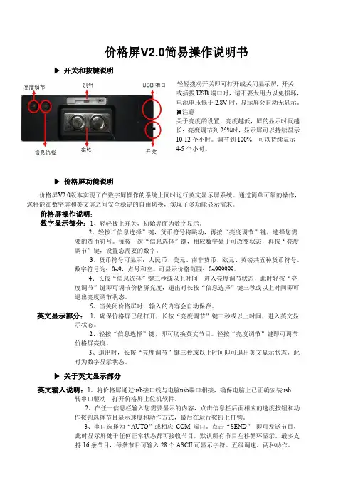
价格屏V2.0简易操作说明书▶开关和按键说明轻轻上下拨轻轻拨动开关即可打开或关闭显示屏, 开关或插拔USB端口时,请不要太用力以免损坏,电池电压低于2.8V时,显示屏会自动无显示。
※注意关于亮度的设置,亮度越低,屏的显示时间越长:亮度调节到25%时,显示屏可以持续显示10-12个小时。
调节到100%,可以持续显示4-5个小时。
▶价格屏功能说明价格屏V2.0版本实现了在数字屏操作的系统上同时运行英文显示屏系统。
通过简单可靠的操作,您将能在数字屏和英文屏之间安全稳定的自由切换,实现了多功能显示需求。
价格屏操作说明:数字显示部分:1、轻轻拨上开关,初始界面为数字显示。
2、轻按“信息选择”键,货币符号将跳动,再按“亮度调节”键,选择您需要的货币符号。
每按一次“信息选择”键,相应数字处于可改变状态,再按“亮度调节”键,设置您需要的数字。
3、货币符号可显示:人民币、美元、南非货币、欧元、英镑共五种货币符号。
数字符号为:0~9,点号和空。
可显示价格范围:0~999999。
4、长按“信息选择”键三秒或以上时间,进入亮度调节状态,此时轻按“亮度调节”键即可调节价格屏亮度,退出时长按“信息选择”键三秒或以上时间即可退出亮度调节状态。
5、当关闭价格屏时,输入的内容会自动保存。
英文显示部分:1、确保价格屏已经打开,长按“亮度调节”键三秒或以上时间,进入英文显示状态。
2、轻按“信息选择”键,即可切换英文节目。
轻按“亮度调节”键即可调节价格屏亮度。
3、退出时,长按“亮度调节”键三秒或以上时间即可退出英文显示状态,此时为数字显示状态。
▶关于英文显示部分英文输入说明:1、将价格屏通过usb接口线与电脑usb端口相接,确保电脑上已正确安装usb 转串口驱动,打开价格屏上位机软件。
2、在任一信息栏输入您需要显示的内容,点击信息栏后面相应的速度按钮和动作按钮选择节目显示速度和动作方式,最后在运行按钮上打钩。
3、串口选择为“AUTO”或相应COM端口。
资料来源:爱购机目录................................................................................................... 错误!未定义书签。
1 外观描述 (2)2 电源键的用法 (3)3 触摸屏 (4)4转接盒 (4)5 SD卡的使用 (5)6开始使用 (5)给设备充电 (5)启动设备 (5)Wi-Fi 网络设置 (5)7桌面 (5)8锁屏界面 (6)9预装程序 (7)10桌面菜单功能 (8)11 程序管理 (10)安装程序 (10)直接从网络上下载程序 (10)卸载程序 (10)12 天气 (10)13 时钟 (11)闹钟 (11)14在线软件安装 (12)菜单功能 (12)15浏览器 (13)16 日历 (13)新建活动 (13)17 相机 (13)拍摄图片 (13)录制视频 (14)18 计算器 (14)19 电子邮件 (14)添加邮件账户 (14)收件箱 (15)编辑邮件账户 (15)删除邮件账户 (16)20 文件浏览器 (16)在电脑和设备之间拷贝文件 (17)删除文件 (17)21 我的音乐 (17)播放音乐 (17)对音乐盒播放列表进行操作 (18)22 我的视频 (18)播放视频 (18)对视频和播放列表进行操作 (19)23 我的相册 (19)涂鸦 (20)24 通讯录 (20)添加新的联系人 (20)添加联系人到收藏 (20)编辑联系人 (20)删除联系人 (20)25 图片截取 (21)26 程序管理器 (21)停止程序 (21)卸载程序 (21)27 YouTube (21)28 土豆视频 (22)29 Wi-Fi设置 (22)30 3G Settings (22)31 连接ADSL上网 (23)32 有线网络 (23)33 设置 (23)常见问题 (25)电池管理 (26)电池充电 (26)重要安全提示 (26)附录.建议可选配件及型号 (27)1 外观描述前视图:右视图:左视图:顶视图:2 电源键的用法开机: 长按电源键2秒。
天马7寸显示屏使用教程
以下是天马7寸显示屏的使用教程:
1. 首先,确认你的天马7寸显示屏已正确连接到你的设备(例如计算机、单板电脑或其他设备)。
确保显示屏的电源线和数据线都连接稳固。
2. 打开你的设备,并进入操作系统或应用程序。
显示屏应该自动被检测到,并开始显示你的内容。
3. 如果显示屏没有自动被检测到,你可以尝试重新插拔显示屏的数据线,或者尝试重启设备。
4. 如果你希望调整显示屏的亮度、对比度或图像效果,你可以在操作系统或应用程序的设置中进行调整。
具体的设置选项取决于你所使用的设备和操作系统。
5. 如果你希望连接多个显示屏来实现扩展屏幕,你需要确保你的设备支持多显示器功能,并按照设备的说明书进行相应设置。
6. 结束使用后,你可以关闭显示屏的电源,并小心地拔掉数据线。
请注意,以上的教程只是一般指南,具体操作可能因设备和操作系统的不同而有所差异。
如果你遇到问题或需要进一步的帮助,建议参考天马7寸显示屏的官方
说明书或向天马客服咨询。
MODEL NO.:TM035KDHG04ISSUED DATE:2012-07-11VERSION:Ver2.0□Preliminary Specification■Final Product SpecificationCustomer:Approved by NotesSHANGHAI TIANMA Confirmed:Prepared by Checked by Approved byThis technical specification is subjected to change without noticeThe information contained herein is the exclusive property of SHANGHAI TIANMA MICRO-ELECTRONICS Corporation,and shall not be distributed,reproduced,or disclosed in whole or in part without prior writtenTable of ContentsCoversheet (1)Record of Revision (3)1.General Specifications (4)2.Input/Output Terminals (5)3Absolute Maximum Ratings (8)4Electrical Characteristics (8)5Timing Chart (10)6Optical Characteristics (18)7Environmental/Reliability Tests (22)8Mechanical Drawing (23)9Packing Drawing (22)10Precautions For Use of LCD modules (26)The information contained herein is the exclusive property of SHANGHAI TIANMA MICRO-ELECTRONICS Corporation,and shall not be distributed,reproduced,or disclosed in whole or in part without prior writtenThe information contained herein is the exclusive property of SHANGHAI TIANMA MICRO-ELECTRONICS Corporation,and shall not be distributed,reproduced,or disclosed in whole or in part without prior writtenRecord of Revision1.General SpecificationsNote1:Viewing direction for best image quality is different from TFT definition,there is a180degree shift.Note2:Requirements on Environmental Protection:Q/S0002Note3:LCM weight tolerance:±5%The information contained herein is the exclusive property of SHANGHAI TIANMA MICRO-ELECTRONICS Corporation,and shall not be distributed,reproduced,or disclosed in whole or in part without prior written2.Input/Output Terminals2.1TFT LCD Panel Matching connector of Kyocera elco:6240serialsThe information contained herein is the exclusive property of SHANGHAI TIANMA MICRO-ELECTRONICS Corporation,and shall not be distributed,reproduced,or disclosed in whole or in part without prior writtenThe information contained herein is the exclusive property of SHANGHAI TIANMA MICRO-ELECTRONICSCorporation,and shall not be distributed,reproduced,or disclosed in whole or in part without prior written 29Note2-1:I/O definition:I----InputO----OutputP----Power/GroundNote2-2:The information contained herein is the exclusive property of SHANGHAI TIANMA MICRO-ELECTRONICS Corporation,and shall not be distributed,reproduced,or disclosed in whole or in part without prior writtenThe information contained herein is the exclusive property of SHANGHAI TIANMA MICRO-ELECTRONICS Corporation,and shall not be distributed,reproduced,or disclosed in whole or in part without prior written 3Absolute Maximum Ratings3.1Driving TFT LCD PanelTa =25℃4Electrical Characteristics4.1Driving TFT LCD PanelGND=0V,Ta=25℃4.2Driving BacklightNote 1:The figure below shows the connectionof backlight LED.Note 2:Each LED :I =20mA,V =3.2VNote 3:The typical LED lifetime is 40,000hours.If LED is driven by high current,high ambient temperature &humidity condition,the lifetime of LED will be reduced.Operating life means brightness goes down to 50%initial brightness.Typical operating lifetime is estimated data.The information contained herein is the exclusive property of SHANGHAI TIANMA MICRO-ELECTRONICS Corporation,and shall not be distributed,reproduced,or disclosed in whole or in part without prior writtenThe information contained herein is the exclusive property of SHANGHAI TIANMA MICRO-ELECTRONICS Corporation,and shall not be distributed,reproduced,or disclosed in whole or in part without prior written4.3Block DiagramSPI Signal POWER SUPPLYB/LRGBITU-R BT 601/656RESET SignalThe information contained herein is the exclusive property of SHANGHAI TIANMA MICRO-ELECTRONICS Corporation,and shall not be distributed,reproduced,or disclosed in whole or in part without prior written 5Timing Chart5.1Timing Parameter(VCC=3.3V GND =0V,Ta=25different.The information contained herein is the exclusive property of SHANGHAI TIANMA MICRO-ELECTRONICS Corporation,and shall not be distributed,reproduced,or disclosed in whole or in part without prior written5.25.3RGB Mode 320RGB x 240Parameter Symbol Min Typ Max Unit Frequency Fclk --2730MHz Time Tclk --37--ns HSYNC toinput(NTSC)Ths 3570255CLKDDLYThe information contained herein is the exclusive property of SHANGHAI TIANMA MICRO-ELECTRONICS Corporation,and shall not be distributed,reproduced,or disclosed in whole or in part without prior written5.5ParameterSymbol Min Typ CLK Frequency Fclk --27CLK TimeTclk--37The information contained herein is the exclusive property of SHANGHAI TIANMA MICRO-ELECTRONICS Corporation,and shall not be distributed,reproduced,or disclosed in whole or in part without prior written Time5.63-Wire Serial Communication AC TimingParameter Symbol Typ Unit Clock T SPCK --Pulse Duty T scdut 50Data Setup T isu --Data Hold T ihd --Clock High/Low T ssw--T cdNote :DDLY Description (Ths=DDLY+Offset)SHANGHAI TIANMA MICRO-ELECTRONICS TM035KDHG04V2.05.73-WireNote:R03:c4h:ITU-R BT656Modec2h:ITU-R BT601Modec8h:8bit RGB Mode(HV Mode)c9h:8bit RGB Mode(DE Mode)cch(default):24bit RGB Mode(HV mode)cdh:24bit RGB Mode(DE mode)R0F:A4h(default):VGH=15V,VGL=-10V.24h(recommend):VGH=15V,VGL=-7V.The information contained herein is the exclusive property of SHANGHAI TIANMA MICRO-ELECTRONICS Corporation,and shall not be distributed,reproduced,or disclosed in whole or in part without prior writtenThe information contained herein is the exclusive property of SHANGHAI TIANMA MICRO-ELECTRONICS Corporation,and shall not be distributed,reproduced,or disclosed in whole or in part without prior written 5.8ResetTimingThe information contained herein is the exclusive property of SHANGHAI TIANMA MICRO-ELECTRONICS Corporation,and shall not be distributed,reproduced,or disclosed in whole or in part without prior written5.9Power Note1.Please exit to Standby Mode through 3-wire command,detail sequence that exit to Standby Modeunder power on mode presentation as below.2.Exit to standby mode,you can write data “0x03”to register “R00”,D09=1for writing data to register.D09=0for reading data from register.Under SPI write mode,D08=X ,and ‘X’means don’t care D08=‘1’or ‘0’.ParameterSymbol Min Typ Max Unit RemarksClock Tspck 320--ns Pulse Duty Tscdut 405060%Data Setup Time Tisu 120--ns Data Hold Time Tihd 120--ns Clock High/Low Tssw 120--ns Tckh or TcklSelect DistinguishTcd1--usThe information contained herein is the exclusive property of SHANGHAI TIANMA MICRO-ELECTRONICS Corporation,and shall not be distributed,reproduced,or disclosed in whole or in part without prior written5.10Power offSequenceNote1.1VS=1VSYNC.Please entry Standby Mode through 3-wire command,detail sequence which enterStandby Mode under power off mode presentation as below.2.Enter to standby mode,you can write data “0x01”to register “R00”,D09=1for writing data to register.D09=0for reading data from register.Under SPI write mode,D08=X ,and ‘X’means don’t care D08=‘1’or ‘0’.ParameterSymbol Min Typ Max Unit RemarksclockTspck 320--ns pulse dutyTscdut 405060%data setup Tisu 120--ns data hold Tihd 120--ns clock high/low Tssw 120--ns Tckh or Tcklselect distinguishTcd1--us6Optical Characteristics6.1Optical SpecificationTa=25℃Test Conditions:1.V F=19.2V,I F=20mA(LED current),the ambient temperature is25℃.2.The test systems refer to Note1and Note2.The information contained herein is the exclusive property of SHANGHAI TIANMA MICRO-ELECTRONICS Corporation,and shall not be distributed,reproduced,or disclosed in whole or in part without prior writtenThe information contained herein is the exclusive property of SHANGHAI TIANMA MICRO-ELECTRONICS Corporation,and shall not be distributed,reproduced,or disclosed in whole or in part without prior written Note 1:Definition of optical measurement system.The optical characteristics should be measured in dark room.After 5minutes operation,the optical properties are measured at the center point of the LCD screen.All input terminals LCD panel must be ground when measuring the center area of the panel.Photo PanelTFT-LCD Note 2:Definition of viewing angle range and measurement system.viewing angle is measured atthe center point of the LCD by CONOSCOPE(ergo-80)。
目錄產品 (2)目錄 (2)功能 (2)省電裝置 (2)即插即用 (2)安全 (3)電器 (3)一般問題 (4)設定您的LCD顯示器 (5)安裝 (5)螢幕調整 (5)OSD 控制 (6)故障排除 (10)產品保養 (11)92GH技術規格 (12)支援顯示模式 (13)22GH技術規格 (14)支援顯示模式 (15)產品註:請保存原包裝盒與包裝材料,以方便日後運送。
目錄LCD 顯示器與底座,請參閱快速設定。
本型號LCD 顯示器配件,請參閱快速設定。
功能影像高亮度 重量輕巧 反應時間快速 立體聲喇叭 省電功能 低電磁波輻射 Kensington 安全卡鎖安全認證省電裝置LCD 顯示器內建電源控制系統,也稱為(省電裝置)。
如有一段時間不使用顯示器時,系統會將顯示器切換到低電壓模式,以節省電力。
稍微移動滑鼠或按下鍵盤按鍵,即可切換到原始畫面。
電腦內的VGA 卡可處理省電裝置功能;您可使用電腦設定此功能。
搭配VESA DPMS 電腦時,本LCD 顯示器與EPA ENERGY STAR 及NÜTEK 相容。
不使用LCD 顯示器時,為了節省電力,請關閉LCD 顯示器的電源。
即插即用新的VESA Plug and Play (VESA 即插即用)功能可簡化複雜與費時的安裝程式。
使用即插即用系統時,不會遭遇常見的安裝問題。
您的電腦系統可輕易識別,並自動調整顯示器。
LCD 顯示器使用Display Data Channel (DDC 顯示資料通道)對電腦系統送出Extended Display Identification Data (EDID 延伸顯示識別資料),因此電腦系統可設定顯示器自動調整。
安全注意:使用顯示器之前,請注意以下的安全警告。
電器檢查電壓 本產品應使用標籤上註明的電源形式進行操作,若您不確定可用的電源形式,請洽詢您的經銷商或當地的電力公司。
電擊本產品配有三頭式接地插頭,其中第三頭為接地線。
天马射电望远镜系统集成监控软件使用手册1.1日期:2017.2.14作者:赵融冰、蒋甬斌、左秀婷赵达新、方铭、欧慧英目录1.集成软件的使用介绍 (4)1.1.软件介绍 (4)1.2.软件的启动 (4)1.2.1.软件的运行 (4)1.2.2.天线界面 (5)1.2.3.天线副面界面 (5)1.2.4.UDC界面 (5)1.2.5.信息表及报警管理Tab页 (7)1.2.6.中频分配界面 (8)1.2.7.接收机Tab界面 (8)1.2.8.SwitchScreen界面 (8)1.2.9.Dibas功率界面 (9)2.TelescopeScreen软件的使用介绍 (9)2.1.TelescopeScreen软件的介绍 (9)2.2.软件的启动 (9)2.2.1.软件的运行 (9)2.2.2.数据面板 (11)2.2.3.状态面板 (11)2.2.4.信息面板 (11)2.2.5.源的设置 (11)2.2.6.控制按钮组 (12)2.2.7.指向模型参数设置 (13)3.SRScreen软件的使用介绍 (13)3.1.软件介绍 (13)3.2.软件启动 (14)3.2.1.运行SRScreen软件 (14)3.2.2.主数据面板 (14)3.2.3 . PosBase (14)3.2.4 . Formula Data (15)3.2.5 . 控制面板 (15)3.2.6 . 连接状态条 (15)4.CRecvScreen软件的使用介绍 (16)4.1.CRecvScreen软件的基本介绍 (16)4.2.CRecvScreen软件的启动 (16)4.2.1.运行CRecvScreen软件 (16)4.2.2.电参数面板 (17)4.2.3.主数据面板 (17)4.2.4.状态面板 (18)4.2.5.信息面板 (18)4.2.6.控制面板 (18)5.SXRecvScreen软件的使用介绍 (19)5.1.SXRecvScreen软件的基本介绍 (19)5.2.SXRecvScreen软件的启动 (19)5.2.1.运行SXRecvScreen软件 (19)5.2.2.电参数面板 (20)5.2.3.主数据面板 (20)5.2.4.状态面板 (21)5.2.5.控制面板 (21)6.KaRecvScreen软件的使用介绍 (22)6.1.KaRecvScreen软件的基本介绍 (22)6.2.KaRecvScreen软件的启动 (22)6.2.1.运行KaRecvScreen软件 (22)6.2.2.电参数面板 (23)6.2.3.主数据面板 (23)6.2.4.状态面板 (24)6.2.5.控制面板 (24)7.LRecvScreen软件的使用介绍 (25)7.1.LRecvScreen软件的基本介绍 (25)7.2.LRecvScreen软件的启动 (25)7.2.1.运行LRecvScreen软件 (25)7.2.2.电参数面板 (26)7.2.3.主数据面板 (26)7.2.4.状态面板 (27)7.2.5.控制面板 (27)8.DBBCScreen软件的使用介绍 (28)8.1.什么是DBBCScreen (28)8.2.如何启动DBBCScreen软件 (28)8.2.1.运行DBBCScreen软件 (28)8.2.2.DBBCScreen 图形界面的组成 (29)8.2.2.1.状态参数显示区域 (29)8.2.2.2.功率时序图显示区域 (29)8.2.2.3.查询控制区域 (30)9.FsScreen软件的使用介绍 (30)9.1.什么是FsScreen (30)9.2.如何启动FsScreen软件 (30)9.2.1.运行FsScreen软件 (30)9.2.2.FsScreen图形界面的组成 (31)9.2.2.1.DBBC监视单元 (31)9.2.2.2.Mark5监视单元 (31)9.2.2.3.Fs Status Monitor单元 (31)9.2.2.4.查询控制单元 (32)10.Mark5b软件的使用介绍 (33)10.1.什么是Mark5b (33)10.2.如何启动Mark5软件 (33)10.2.1.运行Mark5软件 (33)10.2.2.Mark5b图形界面的组成 (34)10.2.2.1.状态参数单元 (34)10.2.2.2.信号灯 (34)10.2.2.3.地址切换单元 (34)10.2.2.4.信息查询及控制单元 (34)11.微波开关控制软件的使用介绍 (35)11.1.什么是微波开关控制软件 (35)11.2.如何启动微波开关控制软件 (35)11.2.1.运行微波开关控制软件 (35)11.2.2.微波开关控制图形界面的组成 (36)11.2.2.1.输入/输出连接控制 (36)11.2.2.2.通信连接状态控制 (36)11.2.2.3.连接状态指示灯 (36)11.2.2.4.输入输出接口信息 (36)11.3.连接状态实时显示 (37)12.DibasScreen软件的使用介绍 (37)12.1.软件介绍 (37)12.2.软件启动 (37)12.2.1.运行DibasScreen软件 (37)12.2.2.状态面板 (38)12.2.2.1. 主状态面板 (38)12.2.2.2. 从状态面板 (39)12.2.3.数据面板 (39)12.2.3.1. 主数据面板 (39)12.2.3.2. 从数据面板 (40)12.2.4.信息面板 (40)12.2.4.1. 主信息面板 (40)12.2.4.2. 从信息面板 (40)13.MonitorComponent的简单介绍 (41)13.1.MonitorComponent的使用方法 (41)13.1.1.绘图面板 (41)13.1.2.绘图面板的设置 (42)14.TeleCurrentScreen软件的使用介绍 (45)14.1.TeleCurrentScreen软件的介绍 (45)14.2.TeleCurrentScreen软件启动 (45)14.2.1.软件的运行 (45)14.2.2.电流监控面板 (46)14.2.3.故障情况监控面板 (46)14.2.4.信息监控面板 (47)1.集成软件的使用介绍1.1.软件介绍天马65米射电望远镜(以下简称65米)天线接收机系统集成软件是一个集成了天马65射电望远镜天线界面软件和接收机界面软件于一体的一套较为完备的望远镜系统软件,较之独立存在的天线软件界面和接收机软件界面,本软件更加方便用户的宏观监控与设置。
泰安天马行车称重显示控制器说明书
泰安天马行车称重显示控制器包含产品的安全提示、技术指标、操作界面、安装配线、功能操作等方面的内容。
为了使本产品保持最佳运行状态,请您在使用前认真阅读本操作手册。
阅读完后,请妥善保存,以备随时查阅。
由于本公司不断致力于产品的技术更新、性能完善与品质提升,可能导致本操作手册与产品实物存在部分差异,届时敬请谅解。
产品主要特点:
1、主要用途:皮带给料机连续配料(流量闭环控制)用,
2、128×64点阵、7色背光液晶显示屏。
3、可设置为中文或英文显示。
4、单单操作与快捷操作(带按键音)。
5、采用高精度高速转换模块与宽频速度脉冲输入电路。
6、可连接8个350Ω称重传感器。
7、具有自动加密、按键加密、按键解密、数字调校、数字设定与接口测试功能。
8、可选用自动校皮(自动零位跟踪)、分段修正、速度校准、带长校准功能。
9、1路可选用的“给定流量”模拟量输入[AI: 4-20mA]
10、最多3路可定义的“流量/控制电..”模拟量信号输出[AO: 4-20mA].
11、具有快速、稳定的配料团环控制功能
12、3路可定义的常开开关输入[DI与4路可定义的继电器或晶体管开关输出[DO].可通过DI&DO开关控制给料机与皮带秤的启停
13、1路“累计量高速脉冲”集电器开路输出[PO]。
14、双通信口可外接上位机、串行打印机、远程显示器、远程操作站与无线通信设备等。
支持各类工业组态软件,如iFix
15、可查询与打印年内的班/日/月产量。
Electric Motorized Projection Screen VMAX 2 SeriesUser’s GuideCaution: The screen’s Black Top Drop is already set to its maximum drop distance. There is NO extra Black Top Drop in the roller. Please be aware of this as it will void your warranty with Elite Screens. Unapproved changes or modifications (except for cutting the power cord for hardwire installations) to this unit are prohibited and will void your warranty. For more information, please contact our Technical SupportDepartment at (877) 511-1211 Ext. 604.•Please retain this user’s guide for future reference.•To avoid damaging the unit, do not use with any unauthorized accessories not recommended by the manufacturer.•Handle the unit carefully during transportation to avoid any damages.•To ensure safe and reliable operation, direct connection to a properly grounded power source is advised.•The power outlet supplying power to the unit should be close to the unit and easily accessible.•Do not install the unit on uneven or inclined surfaces.•Do not put heavy objects on the power cord and position it properly to avoid creating a trip obstacle.•Never overload the power cord to prevent an electric shock or fire due to a loose contact or a short circuit.•There are not user serviceable parts in this unit. Do not attempt to disassemble this unit by yourself. No one except authorized technicians can open and make repairs to thisunit.•Make sure the power source this unit is connected to has a continuous power flow.•If there is need to use an extension cord, make sure the cord has an equal rating as the appliance to avoid overheat.•Do not handle the power plug when your hands are wet or your feet are in contact with water.Do not use this unit under the following circumstances.•Disconnect the power cord under the conditions of heavy rain, wind, thunder or lightning.•Avoid direct Sunshine, rain shower and moisture.•Keep away from fire sources and high temperature to prevent this device from overheating.•Cut off the power supply first before transportation or maintenance.•Fully disconnect from the power supply when the unit is not in use for a long period of time, as should be done with any other electric household appliance.•To avoid possible injury and/or an electric shock, do not attempt to use the screen if there is obvious damage or if there are any evident broken parts.Due to various installation environments, the instructions provided in this user’s guide are for reference only. Please consult a professional installation company for further installation and safety advice. The installer must insure that proper mounting hardware is used to provide adequate strength suitable for the installation. Elite Screens is not liable for any faulty installations.The Screen’s Top Black Drop is already set to its maximum drop distance. There is NO extra top black drop in the roller. Please be aware of this as it will void the limitation of your warranty.Individual modifications to this product are prohibited and will void the warranty with the manufacturer. Please contact Elite Screens Customer Service for any questions.NOTE:This equipment has been tested and found to comply with the limits for a Class B digital device, pursuant to Part 15 of the FCC Rules.These limits are designed to provide reasonable protection against harmful interference in a residential installation. This equipment generates and can radiate radio frequency energy and, if not installed and used in accordance with the instructions, may cause harmful interference to radio communications.However, there is no guarantee that the interference will not occur on a particular installation. If this equipment causes harmful interference to radio or television reception, which can be determined by turning the equipment off and on, the user is encouraged to try to correct the interference by one or more of the following measures.Reorient or relocate the receiving antenna of the device which may be casing the interference.Increase the separation between the screen and the device’s receiver.Connect the equipment into a different power outlet other than the device.1.Carefully unpack the screen.2.Always handle the screen in a leveled position on a clean surface.3.In order to protect the screen from exposure to stains, keep the screen out of contact withforeign particles such as dust, sawdust, and/or liquids.Regardless of the mounting method, the screen should be securely supported so that the vibration or pulling on the viewing surface will not cause the casing to become loose or fall. The installer must insure that the fasteners used are of adequate strength and suitable for the installation location.Red+Green-A. B. C. D.Infrared Remote Radio Frequency 12 Volt Trigger 3 Way Wall Switch D. E. F.Infrared Eye Receiver AAA Batteries Bubble LevelUP1. 5-12V Trigger: The built-in 5-12V trigger input allows your screen to synchronize its drop & rise with the projector’s power cycle. The screen deploys when the projector powers up and will retract when the projector powers down. The 5-12 volt adaptor connects to your projector’s triggeroutput via a separate cable that may or may not be provided by the manufacturer of the projector. The trigger feature will not work without an output cable from the projector, but it can be tested by connecting the Red (+) and Green (-) cable to a 9-volt battery. 3-prong power cable2. 3 -Way Wall Switch: The 3-way wall switch is a wall mount control box with an up/stop/down button and plugs directly into the screen’s RJ-45 input.3. IR “Eye” Receiver: The IR “Eye” Receiver plugs directly into the screen’s RJ-45 input to present a low profile line-of-sight control option for your IR remote control even ina recessed ceiling installation.Please consult a professional installer. Elite Screens is not liable for any faulty installations.1.Select the installation location for your screen. Ensure that it is within reasonable proximity from yourpower source.2.For best support of your screen, it is ideal to secure your screen into the studs of your house’s internalframework. If studs are not available, use hollow anchors for mounting your wall screws into drywall. If you’re installing in a concrete structure, use concrete bolts to secure your screen.Always consult a professional installer or hardware professional to ensure that the proper screws and/or hardware are being used.3.Ensure that both brackets are in perfect level alignment with one another. Use wall/c e iling wood screwsto secure to the wood studs. Use hollow anchors if mounting in drywall.4.The screen casing is designed to accept the wall screws directly. If not using the Optional L-Brackets/accessories.aspx, be sure to position the washer between the head of the wall-screw and the anchor slots on the screen’s casing.ing a tape measure, mark the keyholes that are located at the back of the screen’s casing end cap.6.After marking the area and predrilled hole, insert the screw and have at least 1/8” from the wall to mountthe screen. (See example in Figure 1.)7.Figure 2 will show you an optional installation using chains (not included).For additional information, please contact Elite Screens at ****************************1.If your screen does not move, please check the power supply. The screen will understandablynot move without power.2.Make sure the power cord is firmly plugged to the power outlet.3.Make sure that all cable connections are secure.4.If the screen works well with the line switch but not with the remote control, please make surethe remote controls have fresh batteries. Change the batteries every 6 months to ensure proper operation of the remotes.1.Q: Why does my screen no longer function?A: Make sure your wall plug has power and that the screen is properly plugged. The fuse on the screen will also need to be checked. Please contact **************************** for the location. The tubular motor in this screen is equipped with a thermal relay. This feature will automatically shut off the screen in the event of the motor becoming too hot. This will prevent the motor from overheating. If you should experience this, please let the screen’s temperature decrease for 10-15 min. before usage.2.Q: How is the screen material cleaned?A: The screen material can be cleaned with mild soap and water.3.Q: What type of batteries do the remote controls require?A: The IR and RF remote controls use AAA alkaline batteries.4.Q: Can you manually pull down the screen?A: No, manually pulling down the screen will damage the electronic motor rolling system and void your warranty.5.Q:How could I setup my Screens IR receiver to work with my learning remote control systemDo you have any IR codes I can use to achieve this?A: Our IR remote controls have been evaluated and entered in to the databases of someUniversal remote control manufacturers. Please contact the manufacturer of your remote to inquire about your remotes ability to function with ours. If they have not evaluated our remote control then the following list of Binary codes will be used for most remote setups.For Spectrum, VMAX2 (Plus), Home2 and CineTension 2 SeriesUp: 1111 0000 0001Stop: 1111 0000 0010Down: 1111 0000 0100*Measurement dimensions are intended as a reference only and subject to change without notice. Note: Data Error may be ±1"•Two (2) Year parts and labor warranty from defects in workmanship from purchase date as follows (except for refurbished units as specified below).•Three (3) Year parts and labor warranty from defects in workmanship for GEMR (Government, Educational, Military, & Religious) purchases of new product only.•Refurbished Units carry a 90-DAY parts and labor warranty.•Each party will be responsible for one way shipping during the warranty period.•A RMA (Return Merchandise Authorization) number must be issued in order to process a replacement or to authorize a return for warranty repair. Elite Screens will, at its sole option replace or repair the defective unit with a replacement *(see exceptions below) after thedefective unit or parts have been received. Once the product is received, Elite Screens will send out a replacement *unit to the customer by ground service (subject to inventory availability). •Do Not Return Any Unauthorized Items to Elite Screens, as they will be refused and returned at your expense. The RMA Number must be included on the outside label of your shipping box. Our warehouse is not authorized to accept returns without an RMA number on the shipping label.•RMA Numbers are valid for 45 days from the date issued.•Missing Parts must be reported within 7 days of receipt. If reported after 7 days, the customer will be responsible for shipping and handling fees. If reported after 30 days of receipt, the customer will be responsible for cost of parts and shipping & handling fees.*A New or refurbished replacement will be send out to the customer depending on the type of purchase (new or refurbished) and based on stock availability.North America only U.S. and CanadaFor Warranty and Service requests, please submit an RMA/Service Form at:/warrantysupportformPlease visit this link for full Warranty information:/warrantyFor Customer Service and Technical questions, please contact Elite Screens at:Telephone: (877) 511-1211 ************************Fax: (562) 926-8433 ****************************REMEMBER TO REGISTER YOUR PRODUCT AT:US & Canada Tech Support & Warranty ClaimPlease contact us at ************************ or call +1 877-511-1211 #3 or fax +1-562-926-8433 Europe Tech Support & Warranty ClaimPlease contact us at *********************** or call +49-(0) 40-30392958Asia Tech Support & Warranty ClaimPlease contact us at ************************.cn or call +86-(0) 755-8461-7989Taiwan Tech Support & Warranty ClaimPlease contact us at ************************.tw or call +866+2+8990-1999America:Europe:Elite Screens Inc Elite Screens Europe16410 Manning Way Lübecker Straße 1Cerritos, CA 90703 USA 22087 Hamburg, GermanyTel: +1-877-511-1211 Tel: +49-4030392494Fax: +1-562-926-8433 Fax: +49-40-49219200***************************************** www.elitescreens.euAsia: Elite Screens France S.A.SElite Screens China Corp.11, Allée William PennLongxi Duimianling Industry Zone 92150 Surenes, France Longcheng Longgang District, Tel: +33-1-45064735ShenZhen GuangDong,China Fax: +33-1-45064735Tel:+86-(0)755-8461-7989 ************************Fax:+86-(0)755-8461-7669 /fr*********************.cnJapan:Taiwan: Elite Screens Japan Corp.Elite Screens Taiwan Corp. 467-2-606 Tsuruma, Machida-shi, 4F., No. 42-1 Wuguan Rd. Wugu Township Taipei Tokyo, 194-0004 JapanCounty 248, Taiwan (Wugu Industrial Park) Tel: 0120-07-0008Taiwan (R.O.C) Fax: + 81(0)42-706-9130Tel:+886+2+8990-1999 ********************Fax:+886+2+8990+1366 www.elitescreens.jp*********************.twLatin America Contact:************************East Asia Contact:************************India Contact:***************************。
SHANGHAI AVIC OPTOELECTRONICSTM-产技 1-L-11-A-003-EMODEL NO. : ISSUED DATE: VERSION :TM097TDH01 2010-2-24 Ver. 2.0■Preliminary Specification □Final Product SpecificationCustomer :Approved by NotesSHANGHAI AVIC Confirmed : Prepared by Checked by Approved byStephen Sun 2011/2/24Hyman Chen 2011/2/24Anfernee Du 2011/2/24This technical specification is subjected to change without notice The information contained herein is the exclusive property of SHANGHAI AVIC OPTOELECTRONICS Corporation, and shall not be distributed, reproduced, or disclosed in whole or in part without prior written permission of SHANGHAI AVIC OPTOELECTRONICS Corporation.Page 1 of 20SHANGHAI AVIC OPTOELECTRONICSTM-产技 1-L-11-A-003-ETable of ContentsTable of Contents .............................................................................................................................. 2 Record of Revision............................................................................................................................ 3 1 2 3 4 5 6 7 8 9 General Specifications ............................................................................................................... 4 Input/Output Terminals ............................................................................................................... 5 Absolute Maximum Ratings ....................................................................................................... 7 Electrical Characteristics............................................................................................................ 8 Timing Chart..............................................................................................................................11 Optical Characteristics ............................................................................................................. 14 Environmental / Reliability Test ................................................................................................ 17 Mechanical Drawing................................................................................................................. 18 Packing drawing....................................................................................................................... 1910 Precautions for Use of LCD Modules....................................................................................... 20The information contained herein is the exclusive property of SHANGHAI AVIC OPTOELECTRONICS Corporation, and shall not be distributed, reproduced, or disclosed in whole or in part without prior written permission of SHANGHAI AVIC OPTOELECTRONICS Corporation.Page 2 of 20SHANGHAI AVIC OPTOELECTRONICSTM-产技 1-L-11-A-003-ERecord of RevisionRev 1.0 2.0 Issued Date 2011-2-14 2011-2-24 Description Preliminary Specification Release Change the Viewing Direction Editor Stephen Sun Stephen SunThe information contained herein is the exclusive property of SHANGHAI AVIC OPTOELECTRONICS Corporation, and shall not be distributed, reproduced, or disclosed in whole or in part without prior written permission of SHANGHAI AVIC OPTOELECTRONICS Corporation.Page 3 of 20SHANGHAI AVIC OPTOELECTRONICSTM-产技 1-L-11-A-003-E1 General SpecificationsFeature Size Resolution Interface Color Depth Technology Type Display Spec Pixel Pitch (mm) Pixel Configuration Display Mode Surface Treatment(Up Polarizer) Viewing Direction Gray Scale Inversion Direction Active Area(mm) Mechanical Characteristics With /Without TSP Weight (g) LED Numbers Note 1: Note 2: Note 3: 9.7 inch 1024 (RGB) x 768 RGB 24 bits with TCON 16.7M a-Si 0.192 (H) x 0.192 (V) R.G.B. Vertical Stripe TM with Normally White Anti Glare(3H) 3 o’clock 9 o’clock 196.608 (W) x 147.456 (H) Without TSP TBD 36 LEDs SpecViewing direction for best image quality is different from TFT definition. There is a 180 degree shift. Requirements on Environmental Protection: RoHS LCM weight tolerance: +/- 5%The information contained herein is the exclusive property of SHANGHAI AVIC OPTOELECTRONICS Corporation, and shall not be distributed, reproduced, or disclosed in whole or in part without prior written permission of SHANGHAI AVIC OPTOELECTRONICS Corporation.Page 4 of 20SHANGHAI AVIC OPTOELECTRONICSTM-产技 1-L-11-A-003-E2 Input/Output Terminals2.1 CN1 of FPCPin No. 1 2 3 4 5 6 7 8 9 10 11 12 13 14 15 16 17 18 19 20 21 22 23 24 25 26 27 28 29 30 31 32 33 34 35 36 37 38 39 40 Symbol NC CABC_EN1 CABC_EN0 DIMO GND VCOM DVDD MODE DE VS HS B7 B6 B5 B4 B3 B2 B1 B0 G7 G6 G5 G4 G3 G2 G1 G0 R7 R6 R5 R4 R3 R2 R1 R0 GND DCLK GND L/R U/D I/O P I P I I I I I I I I I I I I I I I I I I I I I I I I I I I I P I P I I Function No connection Power ground Common voltage Power supply 3.3V DE/SYNC mode select Data input enable Vertical sync input Horizontal sync Input Blue data (MSB) Blue data Blue data Blue data Blue data Blue data Blue data Blue data (LSB) Green data (MSB) Green data Green data Green data Green data Green data Green data Green data (LSB) RED data (MSB) RED data RED data RED data RED data RED data RED data RED data (LSB) Power ground Clock for input data Power ground Left/right scan selection Up/down selection Remarks MODE=1, DE mode; MODE=0, HSD/VSD mode. L/R=1, from left to right; L/R=0, from right to left. U/D=0, from up to down; U/D=1, from down to up.The information contained herein is the exclusive property of SHANGHAI AVIC OPTOELECTRONICS Corporation, and shall not be distributed, reproduced, or disclosed in whole or in part without prior written permission of SHANGHAI AVIC OPTOELECTRONICS Corporation.Page 5 of 20SHANGHAI AVIC OPTOELECTRONICS 41 VGH P Gate on voltage 42 VGL P Gate off voltage 43 AVDD P Power for analog circuit 44 RESET I Global reset pin 45 NC No connection 46 VCOM I Common voltage47 48 49 50 DITHB GND NC NC I P Dithering function Power ground No connection No connectionTM-产技 1-L-11-A-003-E DITHB=1, Disable internal dithering function; DITHB=0, Enable internal dithering function -Note:I/O definition. O---Output pin, P--- Power/Ground,N--- No ConnectionI---Input pin, 2.2U/D R/L Function Description Scan Control Input UPDN GND DVDD GND DVDD SHLR DVDD GND GND DVDD Scanning Direction Up to Down, Left to Right Down to Up, Right to Left Up to Down, Right to Left Down to Up, Left to RightThe information contained herein is the exclusive property of SHANGHAI AVIC OPTOELECTRONICS Corporation, and shall not be distributed, reproduced, or disclosed in whole or in part without prior written permission of SHANGHAI AVIC OPTOELECTRONICS Corporation.Page 6 of 20SHANGHAI AVIC OPTOELECTRONICSTM-产技 1-L-11-A-003-E3 Absolute Maximum RatingsAGND= GND=0V, Ta = 25℃ Item Symbol DVDD Power Voltage AVDD VGH VGL Operating Temperature Storage Temperature TOPR TSTG Min -0.5 -0.5 -0.3 VGH-42 -20 -30 Max 5.0 13.5 +42 +0.3 70 80 Unit V V V V ℃ ℃ RemarkThe information contained herein is the exclusive property of SHANGHAI AVIC OPTOELECTRONICS Corporation, and shall not be distributed, reproduced, or disclosed in whole or in part without prior written permission of SHANGHAI AVIC OPTOELECTRONICS Corporation.Page 7 of 20SHANGHAI AVIC OPTOELECTRONICSTM-产技 1-L-11-A-003-E4 Electrical Characteristics4.1 Recommended Operating Condition AGND=GND=0V, Ta = 25℃ Item Digital Supply Voltage Analog Supply Voltage Gate On Voltage Gate Off Voltage Symbol DVDD AVDD VGH VGL Min 3.0 12.3 20.8 -7.5 TBD Typ 3.3 12.5 22 -7.0 TBD Max 3.6 12.7 23.3 -6.5 TBD Unit V V V V V RemarkCommon Electrode VCOM Driving SignalNote: The value is for design stage only.The information contained herein is the exclusive property of SHANGHAI AVIC OPTOELECTRONICS Corporation, and shall not be distributed, reproduced, or disclosed in whole or in part without prior written permission of SHANGHAI AVIC OPTOELECTRONICS Corporation.Page 8 of 20SHANGHAI AVIC OPTOELECTRONICS 4.2 Recommended Driving Condition for BacklightTM-产技 1-L-11-A-003-ETa=25℃ Item Forward Current Forward Voltage Operating Life Time Symbol IF VF Min Typ 120 19.2 30000 Max Unit mA V Hrs Remark 36 LEDs (6 LED Serial, 6 LED Parallel)Note1: For each LED: IF (1/6) =20mA, VF (1/6) =3.2V. Note2: Under LCM operating, the stable forward current should be inputted. And forward voltage is for reference only. Note3: IF is defined for one channel LED. Optical performance should be evaluated at Ta=25℃ only If LED is driven by high current, high ambient temperature & humidity condition. The life time of LED will be reduced. Operating life means brightness goes down to 50% initial brightness. Typical operating life time is estimated data.56Note4: The LED driving condition is defined for each LED module.The information contained herein is the exclusive property of SHANGHAI AVIC OPTOELECTRONICS Corporation, and shall not be distributed, reproduced, or disclosed in whole or in part without prior written permission of SHANGHAI AVIC OPTOELECTRONICS Corporation.Page 9 of 20SHANGHAI AVIC OPTOELECTRONICS 4.3 Power Consumption Item Digital Supply Current Analog Supply Current Gate On Current Gate Off Current Symbol IDVDD IAVDD IVGH IVGL Panel&Gamma Power Consumption Backlight Total Condition DVDD=3.3V AVDD=12.5V VGH=22V VGL=-7.0V Min Typ TBD TBD TBD TBD TBD TBD TBDTM-产技 1-L-11-A-003-E AGND=GND=0V, Ta = 25℃ Max TBD TBD TBD TBD TBD TBD TBD Unit Remark mA mA mA mA mW W W4.4 Block DiagramThe information contained herein is the exclusive property of SHANGHAI AVIC OPTOELECTRONICS Corporation, and shall not be distributed, reproduced, or disclosed in whole or in part without prior written permission of SHANGHAI AVIC OPTOELECTRONICS Corporation.Page 10 of 20SHANGHAI AVIC OPTOELECTRONICSTM-产技 1-L-11-A-003-E5 Timing Chart5.1 TFT-LCD Input Timing DVDD=3.3V, AVDD=10.4V, AGND=GND=0V, Ta=25℃ Parameter DCLK Cycle Time DCLK Pulse Width VSD Setup Time VSD Hold Time HSD Setup Time HSD Hold Time Data Setup Time Data Hold Time DE Setup Time DE Hold Time Symbol Tcph Tcwh Tvst Tvhd Thst Thhd Tdsu Tdhd Tesu Tehd Min 14 40 5 5 5 5 5 5 5 5 Typ 50 Max 60 Unit ns % ns ns ns ns ns ns ns ns Data to DCLK Data to DCLK ConditionsInput Clock and Data timing Diagram:The information contained herein is the exclusive property of SHANGHAI AVIC OPTOELECTRONICS Corporation, and shall not be distributed, reproduced, or disclosed in whole or in part without prior written permission of SHANGHAI AVIC OPTOELECTRONICS Corporation.Page 11 of 20SHANGHAI AVIC OPTOELECTRONICS 5.2 Recommended Timing Setting Of TCONTM-产技 1-L-11-A-003-ETCON (Embedded In Source IC) Input Timing (DCLK, HSD, VSD, DE) DVDD=3.3V, AVDD=10.4V, AGND=GND=0V, Ta=25℃ Parameter DCLK Symbol Fclk th thd HSD thpw thb thfp tv tvd VSD tvpw tvb Min 1 1 Typ 65 1344 1024 160 160 806 768 23 15 Max 140 20 Unit MHZ tclk tclk tclk tclk tclk th th th th th Remarktvfp Note: DE timing refer to HSD, VSD input timing. Vertical input timing Diagram:VSD HSD DENThe information contained herein is the exclusive property of SHANGHAI AVIC OPTOELECTRONICS Corporation, and shall not be distributed, reproduced, or disclosed in whole or in part without prior written permission of SHANGHAI AVIC OPTOELECTRONICS Corporation.Page 12 of 20SHANGHAI AVIC OPTOELECTRONICS Horizontal input timing Diagram:TM-产技 1-L-11-A-003-EHSDDEN5.3POWER ON/OFF SEQUENCEThe information contained herein is the exclusive property of SHANGHAI AVIC OPTOELECTRONICS Corporation, and shall not be distributed, reproduced, or disclosed in whole or in part without prior written permission of SHANGHAI AVIC OPTOELECTRONICS Corporation.Page 13 of 20SHANGHAI AVIC OPTOELECTRONICSTM-产技 1-L-11-A-003-E Ta=25℃6 Optical CharacteristicsItem Symbol Condition θT View Angles θB θL θR Contrast Ratio Response Time White Red Chromaticity Green Blue Uniformity NTSC Luminance Test Conditions: 1. 2. IF= 120 mA, VF=19.2 V and the ambient temperature is 25℃. The test systems refer to Note 1 and Note 2. L CR TON TOFF x y x y x y x y U Backlight is on θ=0° 25℃ CR≧10 Min Typ 70 70 70 60 500 20 0.313 0.329 TBD TBD TBD TBD TBD TBD 75 50 220 -% % cd/m2 Note1 Note6 Note 5 Note1 Note7 Note1 Note5 Max ms Note1 Note3 Note1 Note4 Degree Note 2 Unit RemarkThe information contained herein is the exclusive property of SHANGHAI AVIC OPTOELECTRONICS Corporation, and shall not be distributed, reproduced, or disclosed in whole or in part without prior written permission of SHANGHAI AVIC OPTOELECTRONICS Corporation.Page 14 of 20SHANGHAI AVIC OPTOELECTRONICS Note 1: Definition of optical measurement system.TM-产技 1-L-11-A-003-EThe optical characteristics should be measured in dark room. After 5 Minutes operation, the optical properties are measured at the center point of the LCD screen. All input terminals LCD panel must be ground when measuring the center area of the panel.Photo detector FieldItem Contrast Ratio500mm LCD PanelPhoto detector BM-5A SR-3A TRD100FieldTFT-LCD ModuleLuminance Lum Uniformity Chromaticity Response Time1°-The center of the screenNote 2: Definition of viewing angle range and measurement system. viewing angle is measured at the center point of the LCD by CONOSCOPE(ergo-80)。