6C Series
SPECIFICATIONS STANDARD *SPECIAL ELECTRICAL
Center Frequency (Fc)
3000 to 6000 Mhz 2000 to 9000 MHz 3dB Relative Bandwidth (% of FC) 1 to 2.00.5 to 2.5Number of Sections Available 3 to 6 2 to 7Nominal Impedance 50 Ohms 50 Ohms Maximum Insertion Loss See below See below Maximum VSWR 1.5/1 1.3/1Attenuation in the Stopband
See Graph See Graph Maximum Input Power (Average)(Watts to 10,000 ft.)
25% of PEAK See Standard
Maximum Input Power (Peak)(Watts to 10,000 ft.)
1500 x 3dB BW (MHz)Fc (MHz)See Standard
ENVIRONMENTAL Shock 15 G's 25 G's Vibration 10 G's 20 G's Humidity
90% relative
100% relative
Altitude Unlimited Unlimited
Temperature Range (Operating)0 to + 50 degrees
celsius
-20 to + 70 degrees
celsius
Temperature Range (Non-Operating)-25 to + 70 degrees
celsius
-40 to +85 degrees
celsius
MECHANICAL
Approximate Weight in oz.
0.9 x H x L0.8 x H x L Mounting Provisions See below See below
Special Configurations Consult Factory Consult Factory
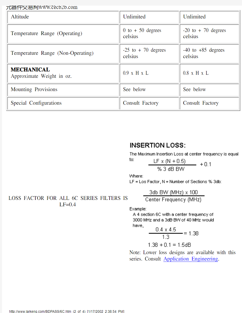
LOSS FACTOR FOR ALL 6C SERIES FILTERS IS
LF=0.4
Note: Lower loss designs are available with this
series. Consult Application Engineering.
MECHANICAL SPECIFICATIONS
L DIMENSION = 0.7 x (NO. OF SECTIONS) + 0.37 inch APPROX.
W DIMENSION = 3000/(CENTER FREQ. MHz) + .75 inch APPROX.
Connectors Available on 6C Series:
Lark Code Type C DIM.Inches & MM Lark Code Type C DIM.Inches & MM A SMA JACK .375 & 9.5G N JACK .736 & 18.7B
SMA PLUG
.507 & 12.9
H N PLUG .819 & 20.8
.
S
SPECIAL
Lark Engineering 6C SERIES
元器件交易网https://www.doczj.com/doc/f41710682.html,
The size shown is a standard used by Lark to facilitate a low cost, easily reproducible unit. Should you require another size, please submit all of your requirements-both electrical and mechanical. This will enable Lark Engineering to quote the
optimum design for your application.
Lark Engineering 6C SERIES
元器件交易网https://www.doczj.com/doc/f41710682.html,
STOPBAND ATTENUATION
The graphs on the following page define the normal specification limits on attenuation Lark bandpass filter series 2C, 3C, 4C, 5C, and 6C. The minimum level of attenuation in dB is shown as a "number of 3dB bandwidths from
center frequency".
The exact relationship is as follows:
1. 3dB Bandwidths From Center Frequency= Rejection Frequency (Mhz) -
Center Frequency (Mhz) divided by 3dB Bandwidth (Mhz)
Example:
Given:
2. Center Frequency = 600 MHz
Minimum 3dB Bandwidth = 6 MHz
Number of Sections = 5
Find: Minimum attenuation levels at 588 MHz and 610 MHz.
3dB BW's from Fc = 588 - 600 / 6 = - 2.0
and 610 - 600 / 6 = + 1.6
The answer can be read directly from the graph. Using the 5 section curve at the point -2.0 (588 MHz) we find the minimum level of attenuation is 62dB. At +1.6 (610 MHz) the minimum level of attenuation is 51dB.
For special requirements, please contact our Application Engineering
Department.
STOPBAND ATTENUATION