White Paper Router Virtualization in Service Providers
Executive Summary
Several factors are contributing to a growing need for virtualization in the point of presence (POP) and data center: a desire to reduce capital costs by buying fewer chassis, a desire to reduce operational costs by deploying fewer chassis and simplifying topologies, and a strong push to decrease the environmental impact by using less power. These goals must coincide with existing requirements of stability, resiliency, and service isolation. This paper discusses how the needs of POP deployments compare and contrast with those of the data center and which virtualization architectures are available to address those needs. It then covers the architectural benefits of virtualization in Cisco? IOS? XR Software that contribute to these goals.
Deployment Considerations
Historically, virtualization occurs much more frequently in the data center than the POP because of cost savings and overlapping administrative domains. However, environmental concerns and recent architectural advances have expanded the possible range of virtualization opportunities outside the data center. High-end routers require substantial power and cooling just for the basic chassis components, so any virtualization can provide a significant power savings by simply adding hardware components to existing equipment. The following sections will analyze two key deployment scenarios – POP and data center – and evaluate the requirements of each.
Data Center
Virtualization in the data center traditionally refers to applications and application servers, such as HTTP and SAP. Because rack space is such a precious resource, adding extra servers and routing instances without an increase in rack space is highly desirable. Space and power are more expensive because typically a third party, not the company deploying the equipment, owns the facilities. Figure 1 provides a typical virtualization topology in a data center environment.
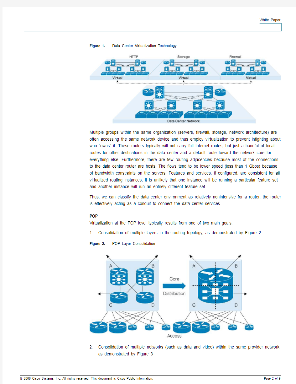
Figure 1. Data Center Virtualization Technology
Multiple groups within the same organization (servers, firewall, storage, network architecture) are often accessing the same network device and thus employ virtualization to prevent infighting about who “owns” it. These routers typically will not carry full Internet routes, but just a handful of local routes for other destinations in the data center and a default route toward the network core for everything else. Furthermore, there are few routing adjacencies because most of the connections to the data center router are hosts. The flows tend to be lower speed (less than 1 Gbps) because of bandwidth constraints on the servers. Features and services, if configured, are consistent for all virtualized routing instances; it is unlikely that one instance will be running a particular feature set and another instance will run an entirely different feature set.
Thus, we can classify the data center environment as relatively nonintensive for a router; the router is effectively acting as a conduit to connect the data center services.
POP
Virtualization at the POP level typically results from one of two main goals:
1. Consolidation of multiple layers in the routing topology, as demonstrated by Figure 2
Figure 2. POP Layer Consolidation
2. Consolidation of multiple networks (such as data and video) within the same provider network,
as demonstrated by Figure 3
Figure 3. POP Network Consolidation
In either case, the feature set can be very different between the two virtual routing instances; a
provider and a provider edge (PE) device have very different roles in a network, and a router in a
data network is likely to have different service requirements than one in a video network. Many
POPs are located on premises owned by the deploying provider, thus they own rack space and
power instead of leasing it. Because the POP is the aggregation point of all customers in a
particular geographical region, the number of routing adjacencies is high, and full Internet routes
are expected to be exchanged with most routing peers. Additionally, these devices aggregate
traffic from lower layers of the network, so the bandwidth demands are extremely high (greater
than 10 Gbps).
Thus, we can classify the POP environment as quite resource-intensive both from a control plane
and data plane perspective.
Tables 1 and 2 summarize deployment considerations for the data center and POP, respectively.
Data Center
Table 1.
Data Center Deployment Considerations Category
Deployment Consideration Characteristic Notes Power and cooling
Expensive Cost Rack space Expensive
Typically leased space, thus higher cost Prefix scalability Very low
Default route to core Routing adjacencies Few
Connected to many hosts, not other routers Scale Bandwidth Low
Constrained by server bandwidth Feature sets between virtualized instances Common
Minimal feature disparity Manageability Administrative domains
Multiple Multiple groups share router
POP
Table 2. POP Deployment Considerations
Category Deployment Consideration Characteristic Notes
Power and cooling Less expensive Cost
Rack space Less expensive Premises typically owned by provider
Prefix scalability High Full Internet routes, possibly
full VPN routes
Routing adjacencies Many Connected to many routers Scale
Bandwidth High Aggregates traffic from lower
layers of network
Feature sets between virtualized instances Different Provider or PE or different
types of networks
Manageability
Administrative domains Single/few Provider and PE same owner,
possibly different groups with
multiple PEs
Virtualization Concepts and Considerations
Though varying degrees of routing virtualization exist, this paper will focus on the two main techniques for creating virtualized router entities as defined by their physical and operational characteristics. A Hardware-Isolated Virtual Router (HVR) has hardware-based resource isolation between routing entities, whereas a Software-Isolated Virtual Router (SVR) comprises software-based resource isolation between routing entities.
Within SVRs, there are several models for achieving virtualization. One model allows for multiple guest operating systems to overlay on a host operating system. This approach tends to have a detrimental impact on scale because it introduces significant contention of resources. Rather than attempting to manage this contention with algorithms and enhancements to divide resources, a common approach overprovisions resources on all SVRs so that no individual SVR is likely to affect the others. Unfortunately, this approach wastes resources while decreasing overall scale.
Another model integrates the virtualization into the kernel itself, a design decision in contrast to the overlay model. Though this technology area is relatively nascent and will surely mature, it still suffers the same fundamental limitations of resource contention. Furthermore, though kernel virtualization could improve the processing performance relative to the overlay model, it introduces extra complexity and instability into the kernel.
A third model does not incorporate multiple operating systems, instead providing virtualization in the individual applications. Though such a model provides better scale from lower overhead, it also complicates the design, testing, and especially management of the SVRs. In addition, it requires the applications to understand some level of virtualization, which requires substantial work on each component individually. This development effort can take a long time before achieving consistency. Thus, there could be incongruence between features supported on standalone systems as opposed to SVRs.
Regardless of the software virtualization model, a common characteristic of SVRs is sharing hardware resources in the data plane. While rudimentary arbitration features like memory partitioning may be employable, high levels of virtualization in the hardware are expensive and thus rarely integrated. As a result, vigilant resource monitoring must extend beyond the control plane.
In contrast, the HVR approach dedicates both control plane and data plane resources on a per-module boundary to individual virtual entities, so there is no sharing of either control plane or data plane resources. It is sometimes said that the only resource HVRs share is sheet metal. A lightweight shim layer provides low-level communication between HVRs, who otherwise believe they are independent router entities. Because of dedicated control plane and data plane resources, software applications and forwarding hardware need not implement virtualization. This separation effectively eliminates arbitration for resources between virtual routing entities.
Table 3 summarizes the defining characteristics of HVRs and SVRs.
Table 3. Comparison of Virtualized Routing Architectures
Category Hardware-Isolated Virtual Router Software-Isolated Virtual Router Control plane resources (CPU, memory) Dedicated Shared
Data plane resources (forwarding
Dedicated Shared
engine, queues)
Shared Shared
Chassis resources (power supplies,
blowers, fabric)
Management, configuration Dedicated Typically shared, but varies depending
on degree of virtualization
Connections between virtualized routing
Typically external Typically internal, but possibly external entities
Increased with additional logical routers Unaffected by additional virtual routers Per-chassis scalability (routing
adjacencies, prefixes)
Discussion
The two approaches have different impacts on considerations that are important to providers. These considerations are key to selecting the proper technology for the virtualization application. Resiliency and Security
A key requirement for deployment is that fundamental aspects of router operation should get no worse as a result of implementing virtualization, and resiliency is among the most important. An outage in one virtual routing entity, whether planned or unplanned, should have no impact on the others. With HVRs, this requirement proves relatively easy to meet because entire physical modules are associated with one and only one virtual routing entity. In contrast, SVR resiliency depends on the virtualization method (overlay, kernel, or application), as well as the quality of the implementation. In most scenarios, however, the lack of physical isolation inherently means that extra care needs to be taken with SVRs to preserve resiliency. Malicious attacks become amplified with the number of SVRs and DoS protection becomes vital. Software defects require additional scrutiny, because multiple SVRs could be affected simultaneously instead of just a single router. Management
The hardware isolation of HVRs makes most aspects of planning straightforward. Because each HVR has dedicated control plane and data plane resources, careful planning and resource management are not necessary. SVRs, on the other hand, require meticulous planning and policy construction to ensure that one SVR does not negatively impact others in the chassis. Constant competition for resources, both in the control plane and the data plane, typically requires constant monitoring and retooling for optimal performance. Because SVRs share so many resources, software isolation can be difficult. Thus, software upgrades and downgrades affect all SVRs and do not allow for individual control. In contrast, the separation of resources between HVRs allows HVRs to be upgraded or downgraded individually without affecting the operation of the others.
Other aspects of management become problematic with SVRs because ownership of the physical nodes is unclear, leading to inconsistencies in configuration maintenance and resource monitoring. A lack of total visibility could prevent the operator from noticing critical trends in overall router functionality (such as CPU utilization or memory usage), with negative impact on resiliency.
One additional issue with management is the connections between virtual routing entities. HVRs typically require external connections, which can increase the total capital expenditure of the solution, but also provide a clean inter-HVR architecture that works exactly the same as a connection to any other router. In contrast, inter-SVR connections typically exist as a kind of a virtual interface. However, these virtual connections must be managed by the software as a special case and do not follow the same forwarding path for normal traffic, instead using one of two approaches:
1. Modifying the existing forwarding path, such that a route lookup may point to a forwarding
table for another SVR. This adds performance impact to the forwarding and can have a drastic impact on the scale from the hardware holding prefixes for all SVRs.
2. Placing the virtual interface on dedicated hardware and offloading the extra processing
through packet diversion. This option has additional challenges, though, as SVRs must share the internal bandwidth to the virtual interface hardware. Without a very robust fabric quality-of-service (QoS) implementation, it is difficult to ensure that inter-SVR traffic will be handled
properly. It must be able not only to prioritize within flows of the same SVR, but also arbitrate between flows from different SVRs, which again adds more complexity and overhead into the forwarding path.
Using dedicated hardware for virtual interfaces consumes space on the router – typically an entry slot that could use a physical interface. This dedicated slot provides some additional forwarding capacity, but often adds nothing to the control plane processing power. HVRs require use of an additional route module to provide control plane and router ownership services, but that extra hardware also adds to the control plane processing power and allows for more routing adjacencies. An external connection is required for HVR, but this paradigm allows for true isolation of HVR resources and precludes the use of complex changes to the forwarding path to allow for inter-HVR forwarding.
Scale
Perhaps the most important distinction between HVRs and SVRs is the direction of scale: does the virtualization technology scale upward or downward? In the case of HVRs, each additional routing entity adds to the number of prefixes, routing adjacencies, and logical interfaces that the chassis can support. In the case of SVRs, each routing entity leaves the number of these scaling elements unchanged or slightly lower from the extra overhead. In essence, an SVR implementation divides the available resources whereas an HVR implementation multiplies the available resources. This important distinction is key to understanding optimal virtualization in various network topologies, as it affects deployment models and solution development.
Deployment Evaluation
Now that we’ve established the characteristics of data centers and POPs, as well as the qualities of SVRs and HVRs, let’s evaluate the compatibility of these virtualization technologies in the two environments.
Data Center
Table 4. Data Center Evaluation
Category Deployment Consideration Characteristic Optimal Virtualization Approach (SVR/HVR)
Power and cooling Expensive
Cost
Rack space Expensive
SVR
Prefix scalability Very low SVR
Routing adjacencies Few SVR Scale
Bandwidth Low SVR
Feature sets between virtualized instances Common Either
Manageability
Administrative domains Multiple Either
In Table 4, it is clear that SVRs are a better match for the data center because of the low scale and price premium for rack space.
POP
Table 5. POP Evaluation
Category Deployment Consideration Characteristic Optimal Virtualization Approach (SVR/HVR)
Power and cooling Less expensive
Cost
Rack space Less expensive
Either
Prefix scalability High HVR
Routing adjacencies Many HVR Scale
Bandwidth High HVR
Feature sets between virtualized instances Different HVR
Manageability
Administrative domains Single/few HVR
In Table 5, it is clear that HVRs are much better suited for POP applications. The amount of scale required is prohibitive for SVRs, as simply running full Internet routes on multiple SVRs could significantly drain the available resources. The multiplicative nature of HVR scalability ensures sufficient resources and provides effectively infinite scale. More importantly, the requirement for a different feature set and the ability to independently manage software on the routing instances make SVRs inherently incompatible.
Note that in data center scenarios where scale and bandwidth requirements increase, such as a hybrid data center router that aggregates greater amounts of routing or traffic, HVRs may also be a better option. In such a case, a routing platform would benefit from offering both SVR and HVR services.
Virtualization in Cisco IOS XR Software: Secure Domain Routers
To accommodate the high bandwidth and control plane needs in provider networks, especially POPs, Cisco IOS XR Software includes support for an HVR technology known as Secure Domain Routers (SDRs). SDRs provide full isolation between virtualized routing instances through the use of Distributed Route Processors (DRPs) for extra control plane resources. SDRs are defined on per-slot boundaries, with entire Route Processors (RPs) and Modular Services Cards (MSCs) dedicated to an SDR. Figure 4 depicts the deployment of SDRs on a Cisco CRS-1 Carrier Routing System running Cisco IOS XR Software.
Figure 4. SDR Example Deployment on Cisco CRS-1/16
In Figure 4, the RPs provide ownership of SDR A, whereas DRPs provide ownership of SDRs B and C. Cisco IOS XR Software allows for partitioning the router in this way to maximize chassis scalability both in terms of control plane and forwarding plane. Each SDR maintains a separate configuration and manages its own interfaces independently of the other SDRs in the chassis. They also maintain separate routing, forwarding, and adjacency tables. In fact, the only parts of the chassis that are shared are the fabric, the fans, and the power supplies, objects that require a marginal amount of environmental monitoring provided by one of the RPs.
Table 6 revisits our previous chart, comparing virtualization approaches with SDRs.
Table 6. Comparison of Virtualization Technologies with Cisco IOS XR Software-Supported Secure Domain Routers
Category Hardware-Isolated Virtual
Router
Software-Isolated Virtual
Router Secure Domain Routers
Control plane resources (CPU,
memory)
Dedicated Shared Dedicated
Data plane resources
(forwarding engine, queues)
Dedicated Shared Dedicated
Chassis resources (power
supplies, blowers, fabric)
Shared Shared Shared
Management, configuration Dedicated Typically shared, but varies
depending on degree of
virtualization
Dedicated
Connections between virtualized routing entities Typically external Typically internal, but possibly
external
External
Per-chassis scalability (routing adjacencies, prefixes) Increased with additional
logical routers
Unaffected by additional virtual
routers
Scales linearly with
number of SDRs
Summary
Both SVRs and HVRs can be part of a provider’s IP Next-Generation Network (NGN) deployment strategy, but care must be taken to ensure the proper application for the particular technologies. If not, a defect, operator error, or malicious attack could have drastic implications on the resiliency of the network. In low-scale and less intensive environments, Software-Isolated Virtual Routers provide the ideal architecture for virtualization. However, control-plane-intensive and high-bandwidth environments require the extra scale offered by Hardware-Isolated Virtual Routers for highly resilient and predictable performance and service. Cisco IOS XR Software’s Secure Domain
Routers provide this HVR functionality and are ideally suited to help providers scale upward as
bandwidth and processing needs increase.
For More Information
For more information about Cisco IOS XR Software Secure Domain Router (SDR), visit
https://www.doczj.com/doc/f21588786.html,/en/US/docs/ios_xr_sw/iosxr_r3.7/system_management/configuration/guide/
yc37sdr.html or contact your local account representative.
For more information about virtualization in service provider POPs, visit: https://www.doczj.com/doc/f21588786.html,/en/
US/prod/collateral/routers/ps5763/prod_white_paper0900aecd8036355e.pdf
For more information about the Virtual Devices Contexts (VDCs) for data centers, visit:
https://www.doczj.com/doc/f21588786.html,/en/US/prod/collateral/switches/ps9441/ps9402/ps9512/White_Paper_Tech_
Overview_Virtual_Device_Contexts.html
For more information about the virtualization architecture using the Cisco Nexus 7000 Series, go
to: https://www.doczj.com/doc/f21588786.html,/en/US/prod/collateral/switches/ps9441/ps9402/ps9512/brochure_
cisco_nexus_7000_series_virtualization_arch.pdf
Printed in USA C11-512753-00 12/08
华三华为交换机路由器 配置常用命令汇总 HUA system office room 【HUA16H-TTMS2A-HUAS8Q8-HUAH1688】
H3C交换机配置命令大全1、system-view 进入系统视图模式 2、sysname 为设备命名 3、display current-configuration 当前配置情况 4、 language-mode Chinese|English 中英文切换 5、interface Ethernet 1/0/1 进入以太网端口视图 6、 port link-type Access|Trunk|Hybrid 设置端口访问模式 7、 undo shutdown 打开以太网端口 8、 shutdown 关闭以太网端口
9、 quit 退出当前视图模式 10、 vlan 10 创建VLAN 10并进入VLAN 10的视图模式 11、 port access vlan 10 在端口模式下将当前端口加入到vlan 10中 12、port E1/0/2 to E1/0/5 在VLAN模式下将指定端口加入到当前vlan中 13、port trunk permit vlan all 允许所有的vlan通过 H3C路由器配置命令大全华为交换机常用配置实例 H3C交换机路由器telnet和console口登录配置 2009年11月09日星期一 10:00
级别说明 Level 名称 命令 参观 ping、tracert、telnet 1 监控 display、debugging 2 配置 所有配置命令(管理级的命令除外)
详解TP-Link路由器设置(图解) 路由器设置图解旨在为搭建网络的初学者准备,技术要点其实没有什么,但是步骤的繁琐让很多人望而怯步,那么这里就向你展示具体操作的整过过程,让你轻松掌握路由器设置. TP-Link路由器设置之设备准备 首先具备的条件是:路由器一个(可以为4口,8口,16口,甚至更多的),如果你有很多台电脑,可以买个多口的交换机.网线直通线数条,电信mode一个(或者你是专线那就不需要mode了),pc电脑至少2台以上(如果只有一台,使用路由器是可以的,但是就失去了使用路由器的意义了. 其实tp-link公司出的路由器,比如TP-LINK TL-402M或者是401M或者是其他型号的tp-link路由器,路由开启方法大多差不多.下面本文以TP-LINK TL-402M为例,请看图片1 图1TP-LINK TL-402M tp-link路由器介绍到这里,大家只要按图片里的介绍,将PC,电信宽带MODE,路由器,相互正确连接,那么一个网络就已经组好了.下面介绍怎么样开启路由功能. TP-Link路由器设置之前期设置: 如果线都已经接好.我们这个时候随便打开一台连好的PC电脑.打开网上邻居属性(图片2),本地连接属性(图片3),tcp/ip 协议属性(图片4),设置ip为192.168.1.2 子网:255.255.255.0 网关:192.168.1.1(图片5)确定,DNS在配置路由器完后在行设置. 注:可以到到控制面板网络连接去设置. 以xp为例,请看图2至图5的细节
图2 打开网上邻居属性 图3 本地连接属性
图4 tcp/ip协议属性
华三系列网络产品 一、路由器 1、H3C CR系列核心路由器 i.H3C CR16000-F 100G核心路由器 产品简介: H3C CR16000-F是H3C自主研发的100G平台核心路由器,采用业界先进的CLOS 交换架构,整机交换容量高达26.88Tbps,采用Comware V7网络操作系统,提供丰富的业务特性和强大的自愈功能,可广泛应用于行业IP专网核心层和汇聚层以及运营商网络MSE等网络位置。 H3C CR16000-F支持主控和交换网板完全物理分离,提供高品质的设备可靠性;支持高密度10GE、40GE、100GE接口,单槽位性能灵活扩展,可以满足不同网络位置需求;支持多维度的虚拟化技术,包括横向虚拟化IRF2、纵向虚拟VCF以及虚拟路由器MDC,可简化网络管理、提高可靠性;支持MSE,集SR和BRAS功能于一身,满足运营商的多业务边缘设备发展需求;支持1588v2以太网时钟同步、TDM仿真以及多种线路保护技术,满足运营商IP RAN组网需求;控制平面采用多核及SMP(Symmetrical Multi-Processing对称多处理)技术,运行先进的操作系统Comware V7,各软件模块具有独立的运行空间,可以动态加载、单独升级,实现ISSU。 产品规格: ii.H3C CR16000核心路由器
产品简介: CR16000 核心路由器(以下简称CR16000)是杭州华三通信技术有限公司自主研发的、基于100G平台的新一代核心路由器,主要应用在运营商IP骨干网、数据中心骨干互联节点以及各种行业大型IP网络的核心和汇聚位置。CR16000先进的体系架构和强大的路由转发性能能够满足用户现在及未来业务扩展的需求。 CR16000采用了创新的硬件架构,可以实现跨板数据的无阻塞交换能力,保障高密度10G 或100G板卡的线速转发;CR16000支持海量的路由表和转发表,作为互联网核心节点能够抵御大路由震荡的冲击,保证数据报文的准确转发;CR16000通过NSR、ISSU、IRF2、APS、BFD等多种高可靠性技术,保证业务永续。 产品规格:
路由器选型重要参数 全双工线速转发能力 路由器最基本且最重要的功能是数据包转发。在同样端口速率下转发小包是对路由器包转发能力最大的考验。全双工线速转发能力是指以最小包长(以太网64字节、POS口40字节)和最小包间隔(20字节)在路由器端口上双向传输同时不引起丢包。该指标是路由器性能重要指标。125,000,000/(64+20)=1,488,095 设备吞吐量 指设备整机包转发能力,是设备性能的重要指标。路由器的工作在于根据IP包头或者MPLS标记选路,所以性能指标是转发包数量每秒。设备吞吐量通常小于路由器所有端口吞吐量之和。 端口吞吐量 端口吞吐量是指端口包转发能力,通常使用pps:包每秒来衡量,它是路由器在某端口上的包转发能力。通常采用两个相同速率接口测试。但是测试接口可能与接口位置及关系相关。例如同一插卡上端口间测试的吞吐量可能与不同插卡上端口间吞吐量值不同。 路由表能力 路由器通常依靠所建立及维护的路由表来决定如何转发。路由表能力是指路由表内所容纳路由表项数量的极限。由于Internet上执行BGP协议的路由器通常拥有数十万条路由表项,所以该项目也是路由器能力的重要体现。 背板能力 背板能力是路由器的内部实现。背板能力能够体现在路由器吞吐量上:背板能力通常大于依据吞吐量和测试包场所计算的值。但是背板能力只能在设计中体现,一般无法测试。QoS分类方式 指路由器可以区分QoS所依据的信息。最简单的QoS分类可以基于端口。同样路由器也可以依据链路层优先级(802.1Q中规定)、上层内容(TOS字段、源地址、目的地址、源端口、目的端口等信息)来区分包优先级。 分组语音支持方式 在企业中,路由器分组语音承载能力非常重要。在远程办公室与总部间,支持分组语音的路由器可以使电话通信和数据通信一体化,有效地节省长途话费。当前技术环境下,分组语音可以分为3种:使用IP承载分组语音、使用A TM承载语音以及使用帧中继承载语音。使用ATM承载语音时可以分AAL1和AAL2两种。AAL1即电路仿真,技术非常成熟但是相对成本较高,AAL2技术较先进,但是当前ATM接口通常不支持。帧中继承载语音也比较成熟,相对成本较低。IP承载语音当前较流行。在上述技术中成本最低,但是当前IP网络QoS保证困难,通话质量较难保证。 语音压缩能力 语音压缩是IP电话节约成本的关键之一。通常可以使用G.723和G.729。G.723在ITU -T建议G.723.1(1996),语音编码器在5.3和6.3Kbps多媒体通信传输双率语音编码器中规定。相对压缩比较高,压缩时延较大。G.729在ITU-T 建议G.729 (1996),8Kbps共扼结构代数码激励线形预测(CS-ACELP)语音编码中规定。压缩比较低,通话质量较好。 信令支持 路由器E1端口上可能支持多种信令:ISUP、TUP、中国1号信令以及DSS1。支持ISUP、TUP或者DSS1信令的路由器可以有效地减少接续时间。在电信级的IP电话网络设备中通常要求支持7号信令。但是作为中低端路由器,通常只支持DSS1和中国1号信令。
Access-enable允许路由器在动态访问列表中创建临时访问列表入口 Access-group把访问控制列表(ACL)应用到接口上 Access-list定义一个标准的IP ACL Access-template在连接的路由器上手动替换临时访问列表入口 Appn向APPN子系统发送命令 Atmsig执行ATM信令命令 B 手动引导操作系统 Bandwidth 设置接口的带宽 Banner motd 指定日期信息标语 Bfe 设置突发事件手册模式 Boot system 指定路由器启动时加载的系统映像 Calendar 设置硬件日历 Cd 更改路径 Cdp enable 允许接口运行CDP协议 Clear 复位功能 Clear counters 清除接口计数器 Clear interface 重新启动接口上的件逻辑 Clockrate 设置串口硬件连接的时钟速率,如网络接口模块和接口处理器能接受的速率Cmt 开启/关闭FDDI连接管理功能 Config-register 修改配置寄存器设置 Configure 允许进入存在的配置模式,在中心站点上维护并保存配置信息 Configure memory 从NVRAM加载配置信息 Configure terminal 从终端进行手动配置 Connect 打开一个终端连接
Copy 复制配置或映像数据 Copy flash tftp 备份系统映像文件到TFTP服务器 Copy running-config startup-config 将RAM中的当前配置存储到NVRAM Copy running-config tftp 将RAM中的当前配置存储到网络TFTP服务器上 Copy tftp flash 从TFTP服务器上下载新映像到Flash Copy tftp running-config 从TFTP服务器上下载配置文件 Debug 使用调试功能 Debug dialer 显示接口在拨什么号及诸如此类的信息 Debug ip rip 显示RIP路由选择更新数据 Debug ipx routing activity 显示关于路由选择协议(RIP)更新数据包的信息 Debug ipx sap 显示关于SAP(业务通告协议)更新数据包信息 Debug isdn q921 显示在路由器D通道ISDN接口上发生的数据链路层(第2层)的访问过程 Debug ppp 显示在实施PPP中发生的业务和交换信息 Delete 删除文件 Deny 为一个已命名的IP ACL设置条件 Dialer idle-timeout 规定线路断开前的空闲时间的长度 Dialer map 设置一个串行接口来呼叫一个或多个地点 Dialer wait-for-carrier-time 规定花多长时间等待一个载体 Dialer-group 通过对属于一个特定拨号组的接口进行配置来访问控制 Dialer-list protocol 定义一个数字数据接受器(DDR)拨号表以通过协议或ACL与协议的组合来控制控制拨号 Dir 显示给定设备上的文件 Disable 关闭特许模式 Disconnect 断开已建立的连接
1、把路由器连接到外网 步骤一:连接好线路 在没有路由器之前,我们是通过电脑直接连接宽带来上网的,那么现在要使用路由器共享宽带上网,当然首先要用路由器来直接连接宽带了。因此我们要做的第一步工作就是连接线路,把前端宽带线连到路由器(WAN口)上,然后把电脑也连接到路由器上(LAN口),如下图: 注意事项 或者是小齿轮图标)是闪烁的。线路连好 ,则表明线路连接有问题,尝试检查下网线连接或换根网注意事项
(若电脑右下角没有网卡图标, ,依次点击
如果您还有苹果的笔记本或iMac产品,设置方法请参考: https://www.doczj.com/doc/f21588786.html,/Service/detail?d=64&t=0 经过上面的配置后,您的电脑就会自动向路由器"索要"IP地址,路由器也会在接收到请求后分配参数给电脑,成功后点击电脑右下角的小电脑图标,在本地连接状态的"支持"选项卡里可以看到电脑获取的参数,如下图(以XP系统为例): <<返回到目录步骤三:设置路由器上网 ①打开网页浏览器,在地址栏输入http://192.168.1.1打开路由器的管理界面,在弹出的登录框中输入路由器的管理帐号(用户名:admin 密码:admin); 如果无法打开路由器的管理界面,请检查输入的IP地址是否正确以及是否把"."输成了中文格式的句号。若仍然不能登陆请参考:登录不了路由器的管理界面怎么办?
②选择"设置向导",点击"下一步"; ③选择正确的上网方式(常见上网方式有PPPOE、动态IP地址、静态IP地址三种,请根据下面的描述选择对应的上网方式); PPPOE:拨号上网,单机(以前没使用路由器的时候)使用Windows系统自带的宽带连接 来拨号,运营商给了一个用户名和密码。这是目前最常见的上网方式,ADSL线路一般都是该上网方式。 PPPOE要输入宽带的用户名和密码 注意事项
cisco路由器常用命令 1:三大模式 router> 用户模式 router > enable 进入特权模式 router # router > enable 进入全局配置模式 router #configure terminal router (conf)# 2:其它模式 Router(config)#interface f1/0 进入接口配置模式Router(config-if)# Router(config)#interface f1/0.1 进入子接口配置模式Router(config-subif)# Router(config)#line console 0 进入line模式Router(config-line)# Router(config)#router rip 进入路由模式Router(config-router)# 3:路由器命名 hostname routera,以routerA为例 router > enable router #configure terminal router(conf)#hostname routerA routera (conf)# 4:配置各类密码 配置特权模式密码(使能口令) enable password cisco,以cisco为例 router > enable router #configure terminal router(conf)#hostname routerA routerA (conf)# enable password cisco 设置VTY(虚拟终端接口)密码 Router(config)#line vty 0 1
Cisco常用配置命令Cisco常用配置命令 一.交换机的基本配置 C2950# config terminal 进入全局配置模式 show interface fastethernet0/1 查看端口0/1的配置结果 show interface fastethernet0/1 status 查看端口0/1的状态 show mac-address-table 查看整个MAC地址表 clear mac-address-table restricted static 清除限定性地址 C2950(config)# hostname 2950A / 设置主机名为2950A interface f0/23 / 进入端口23的配置模式 enable password cisco / 设置enable password为cisco enable secret cisco1 / 设置enable secret为cisco1 ip address 192.168.1.1 255.255.255.0 / 设置交换机IP 地址 ip default-gateway 192.168.1.254 / 设置默认网关 ip domain-name https://www.doczj.com/doc/f21588786.html, / 设置域名 ip name-server 200.0.0.1 / 设置域名服务器 配置查看MAC地址表 mac-address-table ? mac-address-table aging-time 100 / 设置超时是时间为100s mac-address-table permanent https://www.doczj.com/doc/f21588786.html, /f0/3 加入永久地址mac-address-table restricted static 0000.0c02.bbcc / f0/6 f0/7 加入静态地址 end show mac-address-table /查看整个Mac地址表 clear mac-address-table restricted static C2950(config-if)# interface fastethernet0/1 /进入接口F0/1子配置模式 interface Ethernet0 /进入以太网口0子配置模式 no shutdown /激活接口 speed ? /查看speed命令的子命令 speed 100 /设置该端口速率为100Mb/s dulplex full/half/auto /设置该端口为全双工 description TO_PC1 /设置该端口描述为TO_PC1 show interface fastethernet 0/1 /查看端口0/1的配置结果 show interface fastethernet 0/1 status /查看端口0/1的状态 配置VTP和STP 一. 配置VTP 2950A #vlan database /进入VLAN配置子模式 show vtp status /查看VTP设置信息 show vlan /查看VLAN配置信息 copy running-config startup-config /保存配置文件 2950A(vlan)#vtp server/client /设置本交换机为server/client模式
路由器处理器类型和内存容量参数是怎样的篇一:路由器主要参数的识别教程路由器主要参数的识别教程路由器怎么使用?你知道吗?也许有的人会回答,很简单,就是把宽带账号绑定进去就可以了,是的路由器设置非常简单,但是,路由器主要参数你知道吗?一、路由器主要参数:处理器主频分析:首先,路由器的处理器同电脑主板、交换机等产品一样,是路由器最核心的器件。 处理器的好坏直接影响路由器的性能,处理能力差的处理器,路由器性能好不了,但反过来处理器好了,路由器性能却未必就好,因为处理器不是决定路由器的惟一因素。 其次,市面上常有些路由器宣称诸如“处理器主频100,性能强劲”之类。 其实,除了处理器的主频外,还必须了解其总线宽度、容量和结构、内部总线结构、是单还是多分布式处理、运算模式等等,这些都会极大地影响处理器性能,一点也不比主频次要,关键要看这颗到底用的是什么内核,内部结构如何。 用户进阶:一般来说,处理器主频在100或以下的属于较低主频,100~200中等,200以上属于较高主频。 另外要看处理器是什么内核,是80186、7、9、还是?容量有多大?是单还是多分布式处理?80186、7内核处理器是第一代宽带路由器的典型配置,性能低,主流厂商均已不使用。 9、内核处理器是目前主流。 架构是高级网络处理器,用于高端产品。 容量8或以下属于少的,16常见,32或以上是属于大的。 一般处理器都是单,采用多分布式处理的是高级处理器,性能高。 还可以深究一下9是普通型的920922940还是增强型的926946966,是2、3还是4、5,不同型号性能和结构都会有较大差异。 有兴趣可以到网上按处理器型号搜索一下,然后到芯片厂家的网站上好好看个究竟。 二、路由器的主要参数:内存容量分析:处理器内存是用来存放运算过程中的所有数据,因此内存的容量大小对处理器的处理能力有一定影响。 但有一个问题:内存的大小是一方面,能否科学地使用更重要。
路由基础配置命令UTP双绞线类型: 直通线: 交叉线: 广域网线缆连接类型: DTE: DCE: 时钟速率: 路由器的接口:(作用) 1. 广域网接口: serial 2. 内网接口: fastethernet 3. 管理接口: console (控制台) AUX(备份) 连接两个设备: 1. 物理连接 2. 逻辑连接 配置网络设备: 1. 管理属性:用户名密码描述警告 2. 协议地址:IP IPX 3. 协议策略:vlan 静态访问控制 交换机直接可以应用 路由器需要初始配置才能应用 设备启动过程: 1. 加电自检 2. 查找加载操作系统 3. 查找加载配置文件 配置网络设备方式: 1. 初始配置:console 2. 初始配置后通过interface(拥有ip地址的接口): 1)telnet 2)TFTP 3)WEB 4)网络管理工具: SNA SDM 配置直接应用到内存
登陆路由器: Router> Router>enable /*进入特权模式 Router# Router#disable /*退出特权模式 Router> Router>logout /*退出路由器 Router>exit /*退出路由器 路由器IOS帮助功能:?的三个用法 1/ 直接问号 2/ Router#cl? clear clock Router#cl 3/ Router#clock % Incomplete command. Router#clock ? set Set the time and date Router#clock 问号的帮助功能:(查找路由器设置时间的命令并设置时间) Router#cl? clear clock Router#clock % Incomplete command. Router#clock ? set Set the time and date Router#clock set % Incomplete command. Router#clock set ? hh:mm:ss Current Time Router#clock set 11:04:50 % Incomplete command. Router#clock set 11:04:50 ? <1-31> Day of the month MONTH Month of the year Router#clock set 11:04:50 15
NE40E系列 路由器 参数报价分析 张磊
目录 系列路由器简介 (3) 产品结构分析 (4) 3.单板介绍 (4) 单板分类 (4) SRU 板和LPU 板的外观部件 (6) 板间关系 (6) 接口种类及在单板上的分布 (6) 4.路由交换板(SRU)简介 (8) SRU路由交换板外观及描述 (8) 功能简介 (9) 作为系统控制和管理核心,可以实现以下功能: (10) 系统交换网的组成部分 (10) 系统时钟单元 (10) 交换同步时钟单元 (11) 系统维护单元 (11) 5.交换网板SFU (11) SFU 面板的外观 (11) .功能简介 (12) 6.线路处理板LPU (12) LPU板外观 (12) 功能简介 (13) LPU 模块主要功能 (13) FAD 模块 (13) LPU 板种类 (14) 7.产品型号对比 (14)
系列路由器简介 NE40E是华为公司的新一代面向万兆级边缘交换路由器,主要应用在企业广域网核心节点、大型企业接入节点、园区互联&汇聚节点以及其他各种大型IDC网络的边缘位置。NE40E的机箱基于运营级设计,支持单板热插拔,NE40E基于最新的可扩展2T平台,每槽位最大提供1T路由线卡,兼容现网线卡,最大限度保护客户的投资。NE40E具有强大的汇聚接入能力,凭借丰富的特性支持,可以灵活部署L2VPN、L3VPN、组播、组播VPN、MPLS TE、QoS等,实现用户业务的可靠承载;支持丰富的增值业务特性,如GRE隧道、IPSec安全隧道、NetStream等;同时,NE40E 全面支持IPv6,可以实现IPv4到IPv6的平滑过渡。因此,NE40E可以灵活应用在IP/MPLS网络的边缘、核心,可以简化网络结构,提供丰富的业务类型和可靠的服务质量,是IP/MPLS承载网向宽带化、安全化、业务化、智能化发展的重要源动力。 NE40E系列主要包括NE40E-X16、NE40E-X8、NE40E-X3三种类型,适应不同规模的组网需求
C路由器常用基本配置命 令 Revised by Jack on December 14,2020
H3C路由器常用基本配置命令 [Quidway]sysname router_name命名路由器(或交换机) [Quidway]delete删除Flash ROM中的配置 [Quidway]save将配置写入Flash ROM [Quidway]interface serial 0进入接口配置模式 [Quidway]quit退出接口模式到系统视图 [Quidway]shutdown/undo shutdown关闭/重启接口 [Quidway]ip address ip_address subnet_mask为接口配置IP地址和子网掩码 [Quidway]display version显示VRP版本号 [Quidway]display current-configuration显示系统运行配置信息 [Quidway]display interfaces显示接口配置信息 [Quidway]display ip routing显示路由表 [Quidway]ping ip_address测试网络连通性 [Quidway]tracert ip_address测试数据包从主机到目的地所经过的网关 [Quidway]debug all打开所有调试信息 [Quidway]undo debug all关闭所有调试信息 [Quidway]info-center enable开启调试信息输出功能 [Quidway]info-center console dubugging将调试信息输出到PC [Quidway]info-center monitor dubugging将调试信息输出到Telnet终端或哑终端 换机配置命令举例(大括号{}中的选项为单选项,斜体字部分为参数值 [Quidway]super password password修改特权模式口令 [Quidway]sysname switch_name命名交换机(或路 [Quidway]interface ethernet 0/1进入接口视图 [Quidway]quit退出系统视图 [Quidway-Ethernet0/1]duplex {half|full|auto}配置接口双工工 [Quidway-Ethernet0/1]speed {10|100|auto}配置接口速率 [Quidway-Ethernet0/1]flow-control开启流控制 [Quidway-Ethernet0/1]mdi {across|normal|auto}配置MDI/MDIX [Quidway-Ethernet0/1]shutdown/undo shutdown关闭/重启端口 VLAN基本配置命令(以Quidway S3026为例) [Quidway]vlan 3创建并进入VLAN配置模式,缺省时系统将所有端口加入VLAN 1,这个端口既不能被创建也不能被删除。 [Quidway]undo vlan 3删除一个VLAN [Quidway-vlan3]port ethernet 0/1 to ethernet 0/4给VLAN增加/删除以太网接口
通用路由器配置说明 一、网络摄像机外网访问在公司路由器里的设置 点击转发规则 虚拟服务器 内部端口,外部端口填写网络摄像机里配置的端口,IP是网络摄像机里填写的IP地址填写完确定就行了。
因iCanSee系统完全基于网络运行,路由器在其中扮演了重要的角色。本文以TP-LINK无线路由器为例,简要说明路由器的配置 一、TP-Link TL-WRXX系列路由器配置指南 对路由器进行基本配置,使电脑通过路由器实现共享上网,过程相对来说比较容易实现;这篇文档下面的内容,主要讲述如下几部分: 收集并判断信息,为配置路由器做准备; 进入路由器管理界面,对路由器进行配置; 配置过程简单的故障定位排除!
1、配置路由器前的准备工作 常见的硬件连接方式有下面几种: 电话线→ADSL MODEM→电脑 双绞线(以太网线)→电脑 有线电视(同轴电缆)→Cable MODEM→电脑 光纤→光电转换器→代理服务器→PC ADSL / VDSL PPPoE:电脑上运行第三方拨号软件如Enternet300或WinXP 系统自带的拨号程序,填入ISP提供的账号和密码,每次上网前先要拨号; 或者您的ADSL MODEM已启用路由功能,填入了ISP提供的账号和密码,拨号的动作交给MODEM 去做; 静态IP:ISP提供给您固定的IP地址、子网掩码、默认网关、DNS; 动态IP:电脑的TCP/IP属性设置为“自动获取IP地址”,每次启动电脑即可上网; 802.1X+静态IP:ISP提供固定的IP地址,专用拨号软件,账号和密码; 802.1X+动态IP:ISP提供专用拨号软件,账号和密码; WEB认证:每次上网之前,打开IE浏览器,先去ISP指定的主页,填入ISP提供的用户名密码,通过认证以后才可以进行其他得上网操作; 2、怎样进入路由器管理界面? 先参照《用户手册》上面的图示,将ADSL MODEM、路由器、电脑连结起来。TL-W RXX系列路由器的管理地址出厂默认: IP地址:192.168.1.1, 子网掩码:255.255.255.0 (TL-R400和TL-R400+两款的管理地址默认为:192.168.123.254,子网掩码:255. 255.255.0) 用网线将路由器LAN口和电脑网卡连接好,因为路由器上的以太网口具有极性自动翻转功能,所以无论您的网线采用直连线或交叉线都可以,需要保证的是网线水晶头的制作牢靠稳固,水晶头铜片没有生锈等。 电脑桌面上右键点击“网上邻居”→“属性”,在弹出的窗口中双击打开“本地连接”,在弹出的窗口中点击“属性”,然后找寻“Internet协议(TCP/IP)”,双击弹出“Intern et协议(TCP/IP)属性”窗口; 在这个窗口中选择“使用下面的IP地址”,然后在对应的位置填入: IP地址:192.168.1.X(X范围2-254) 子网掩码:255.255.255.0 默认网关:192.168.1.1,填完以后““确定”两次即可;
欢迎阅读H3C交换机配置命令大全 1、system-view 进入系统视图模式 2、sysname 为设备命名 3、display current-configuration 当前配置情况 4、language-mode Chinese|English 中英文切换 5、interface Ethernet 1/0/1 进入以太网端口视图 6、port link-type Access|Trunk|Hybrid 设置端口访问模式 7、undo shutdown 打开以太网端口 8、shutdown 关闭以太网端口 9、quit 退出当前视图模式 10、vlan 10 创建VLAN 10并进入VLAN 10的视图模式 11、port access vlan 10 在端口模式下将当前端口加入到vlan 10中 12、port E1/0/2 to E1/0/5 在VLAN模式下将指定端口加入到当前vlan中 13、port trunk permit vlan all 允许所有的vlan通过 H3C路由器配置命令大全华为交换机常用配置实例 H3C交换机路由器telnet和console口登录配置 2009年11月09日星期一 10:00 级别说明 Level 名称 命令 参观 ping、tracert、telnet 1 监控 display、debugging
2 配置 所有配置命令(管理级的命令除外) 3 管理 文件系统命令、FTP命令、TFTP命令、XMODEM命令 telnet仅用密码登录,管理员权限 [Router]user-interface vty 0 4[Router-ui-vty0-4]user privilege level 3[Router-ui-vty0-4]set authentication password simple abc telnet仅用密码登录,非管理员权限 [Router]super password level 3 simple super [Router]user-interface vty 0 4[Router-ui-vty0-4]user privilege level 1[Router-ui-vty0-4]set authentication password simple abc telnet使用路由器上配置的用户名密码登录,管理员权限 [Router]local-user admin password simple admin[Router]local-user admin service-type telnet[Router]local-user admin level 3 [Router]user-interface vty 0 4[Router-ui-vty0-4]authentication-mode local telnet使用路由器上配置的用户名密码登录,非管理员权限 [Router]super password level 3 simple super [Router]local-user manage password simple manage[Router]local-user manage service-type telnet[Router]local-user manage level 2 [Router]user-interface vty 0 4[Router-ui-vty0-4]authentication-mode local 对console口设置密码,登录后使用管理员权限 [Router]user-interface con 0[Router-ui-console0]user privilege level 3[Router-ui-console0]set authentication password simple abc 对console口设置密码,登录后使用非管理员权限 [Router]super password level 3 simple super [Router]user-interface con 0[Router-ui-console0]user privilege level 1[Router-ui-console0]set authentication password simple abc 对console口设置用户名和密码,登录后使用管理员权限 [Router]local-user admin password simple admin[Router]local-user admin service-type terminal[Router]local-user admin level 3 [Router]user-interface con 0[Router-ui-console0]authentication-mode local 对console口设置用户名和密码,登录后使用非管理员权限 [Router]super password level 3 simple super [Router]local-user manage password simple manage[Router]local-user
主机路由表介绍 在windows中,保存着一张路由表。这张路由表根据实际情况的不同而不同。它是保证本机能上网不可缺少的一项。在windows的命令提示符下输入:route print ,可查看当前路由表信息。 (假设本机IP:网关: 解释: 第一条: 1
缺省路由:意思就是说,当一个数据包的目的网段不在你的路由记录中,那么,你的主机该把那个数据包发送到那里!缺省路由的网关是由你的连接上的default gateway决定的。 该路由记录的意思是:当我接收到一个数据包的目的网段不在我的路由记录中,我会将该数据包通过这个接口发送到这个地址,这个地址是下一个路由器的一个接口,这样这个数据包就可以交付给下一个路由器处理,与我无关。该路由记录的路由代价 20。 第二条: 本地环路:这个网段内所有地址都指向自己机器,如果收到这样一个数据,应该发向哪里该路由记录的路由代价 1 第三条: 直联网段的路由记录:当主机发往直联网段的数据包时该如何处理,这种情况,路由记录的interface和gateway是同一个。当我接收到一个数据包的目的网段是时,我会将该数据包通过这个接口直接发送出去,因为这个端口直接连接着这个网段,该 2
路由记录的路由代价 20 第四条: 本地主机路由:当主机发送给自己的数据包时将如何处理 当我接收到一个数据包的目的网段是时,我会将该数据包收下,因为这个数据包时发送给我自己的,该路由记录的路由代价 20第五条: 本地广播路由:当主机发送给直联网段的广播时如何处理 当我发送到广播数据包的目的网段是时,我会将该数据从接口以广播的形势发送出去,该路由记录的路由代价 20 第六条: 3
思科路由器查看配置命令 show run// 看运行状况 show ip route// 看路由表 show int// 看断口 * show ip int br// 看端口 ip 地址 show cdp nei// 察看 cdp 邻居 show ip pro// 察看 ip 协议 查看配置信息用 show 命令,该命令可以在用户模式和特权模式下执行,且在特权模式下看 到的信息比用户模式多。 show 命令很多,常用的有: 1、查看运行配置文件: Router#show running-config 运行配置文件 running-config 位于路由器的 RAM 中,存放的是路由器当前使用的配置信息。 2、查看启动配置文件: Router#show startup-config 启动配置文件 startup-config 位于路由器的 NVRAM 中,可以长期保存。它在启动路由器时装入 RAM ,成为 running-config 。 3、查看路由器的版本信息: Router#show version' 4、查看路由器的接口状态: Router#show ip interface brief 如果接口状态标识为“ Down ”,表示此接口未激活,如果标识为“ Up”,表示此接口已经激活。 5、查看路由表:
Router#show ip route 通过路由表可以看出该路由器已经识别的网络。 6、查看 NAT 翻译情况: Router#show ip nat translation 应该先进行内网与外网的通讯(如:用 ping 命令 ),然后再查看,才能看到翻译情况。
思科中路由器的基础配置命令。 Cd 更改路径 Cdp enable 允许接口运行CDP协议 Clear 复位功能 Clear counters 清除接口计数器 Clear interface 重新启动接口上的件逻辑 Clockrate 设置串口硬件连接的时钟速率,如网络接口模块和接口处理器能接受的速率Cmt 开启/关闭FDDI连接管理功能 Config-register 修改配置寄存器设置 Configure 允许进入存在的配置模式,在中心站点上维护并保存配置信息 Configure memory 从NVRAM加载配置信息 Configure terminal 从终端进行手动配置 Connect 打开一个终端连接 Copy 复制配置或映像数据 Copy flash tftp 备份系统映像文件到TFTP服务器 Copy running-config startup-config 将RAM中的当前配置存储到NVRAM Copy running-config tftp 将RAM中的当前配置存储到网络TFTP服务器上 Copy tftp flash 从TFTP服务器上下载新映像到Flash Copy tftp running-config 从TFTP服务器上下载配置文件 Debug 使用调试功能 Debug dialer 显示接口在拨什么号及诸如此类的信息 Debug ip rip 显示RIP路由选择更新数据
Debug ipx routing activity 显示关于路由选择协议(RIP)更新数据包的信息 Debug ipx sap 显示关于SAP(业务通告协议)更新数据包信息 Debug isdn q921 显示在路由器D通道ISDN接口上发生的数据链路层(第2层)的访问过程 Debug ppp 显示在实施PPP中发生的业务和交换信息 Delete 删除文件 Deny 为一个已命名的IP ACL设置条件 Dialer idle-timeout 规定线路断开前的空闲时间的长度 Dialer map 设置一个串行接口来呼叫一个或多个地点 Dialer wait-for-carrier-time 规定花多长时间等待一个载体 Dialer-group 通过对属于一个特定拨号组的接口进行配置来访问控制 Dialer-list protocol 定义一个数字数据接受器(DDR)拨号表以通过协议或ACL与协议的组合来控制控制拨号 Dir 显示给定设备上的文件 Disable 关闭特许模式 Disconnect 断开已建立的连接 Enable 打开特许模式 Enable password 确定一个密码以防止对路由器非授权的访问 Enable password 设置本地口令控制不同特权级别的访问 Enable secret 为enable password命令定义额外一层安全性(强制安全,密码非明文显示) Encapsulation frame-relay 启动帧中继封装 Encapsulation novell-ether 规定在网络段上使用的Novell独一无二的格式 Encapsulation PPP 把PPP设置为由串口或ISDN接口使用的封装方法