Modbus Protocol RTU Mode Reference Guide
RTU Mode
When controllers are setup to communication on a Modbus network using RTU(Remote Terminal Unit) mode, each 8-bit byte in a message contains two 4-bit hexadecimal characters. The main advantage of this mode is that its greater character density
allows better data throughput than ASCII for the same baud rate. Each message must
be transmitted in a continuous stream.
The format for each byte in RTU mode is:
Coding System: 8-bit binary, hexadecimal 0-9,A-F Two hexadecimal
characters
Contained in each 8-bit field of the message
Bits per Byte: 1 start bit
8 data bit, least significant bit sent first
1 bit for even/odd parity; no bit for no parity
1 stop bit if parity is used;
2 bits if no parity
Error Check Field: Cyclical Redundancy Check (CRC)
Modbus Message Framing
In either of the two serial transmission modes(ASCII or RTU),a Modbus message is placed by the transmitting device into a frame that has a known beginning and ending point. This allows receiving devices to begin at the start of the message, read the address portion and determine which device is addressed(or all devices, if the message is broadcast),and to know when the message is completed. Partial messages can be detected and errors can be set as a result.
On networks like MAP or Modbus Plus, the network protocol handles the framing of messages with beginning and end delimiters that are specific to the network. Those protocols also handle delivery to the destination device, making the Modbus address field imbedded in the message unnecessary for the actual transmission.(The Modbus address is converted to a network node address and routing path by the or originating controller or its network adapter.)
RTU Framing
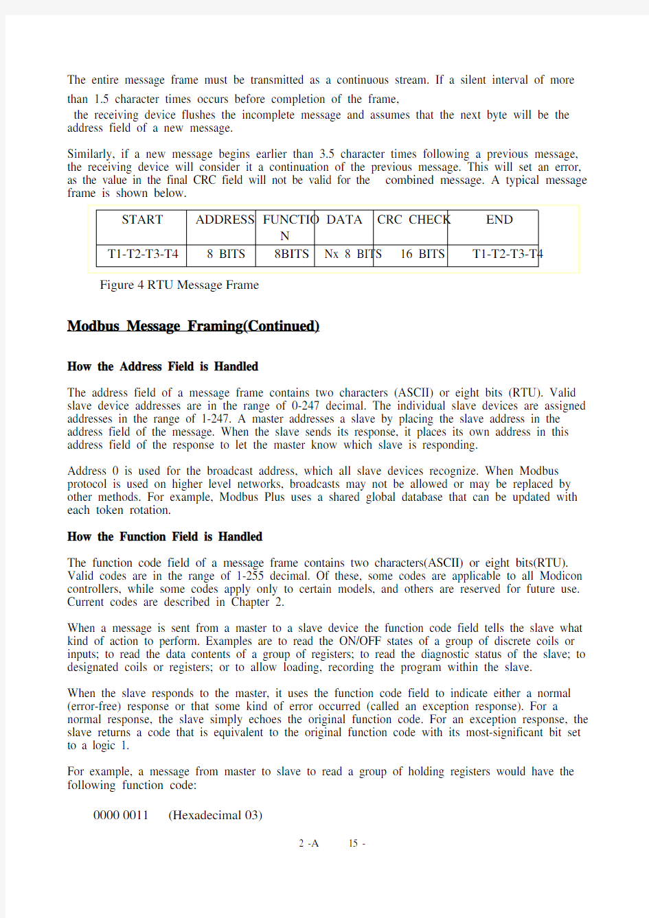
In RTU mode, messages start with a silent interval of at least 3.5 character times. This is most easily implemented as a multiple of character times at the baud rate that is being used on the network (shown as T1-T2-T3-T4 in the figure below).The first field then transmitted is the device address.
The allowable characters transmitted for all fields are hexadecimal 0-9,A-F.
Networked devices monitor the network bus continuously, including during the “silent” intervals. When the first field (the address field) is received, each device decodes it to find out if it is the addressed device.
Following the last transmitted chatacter, a similar interval of at least 3.5 character times marks the end of the message. A new message can begin after this interval.
The entire message frame must be transmitted as a continuous stream. If a silent interval of more than 1.5 character times occurs before completion of the frame,
the receiving device flushes the incomplete message and assumes that the next byte will be the address field of a new message.
Similarly, if a new message begins earlier than 3.5 character times following a previous message, the receiving device will consider it a continuation of the previous message. This will set an error, as the value in the final CRC field will not be valid for the combined message. A typical message frame is shown below.
Modbus Message Framing(Continued)
How the Address Field is Handled
The address field of a message frame contains two characters (ASCII) or eight bits (RTU). Valid slave device addresses are in the range of 0-247 decimal. The individual slave devices are assigned addresses in the range of 1-247. A master addresses a slave by placing the slave address in the address field of the message. When the slave sends its response, it places its own address in this address field of the response to let the master know which slave is responding.
Address 0 is used for the broadcast address, which all slave devices recognize. When Modbus protocol is used on higher level networks, broadcasts may not be allowed or may be replaced by other methods. For example, Modbus Plus uses a shared global database that can be updated with each token rotation.
How the Function Field is Handled
The function code field of a message frame contains two characters(ASCII) or eight bits(RTU). Valid codes are in the range of 1-255 decimal. Of these, some codes are applicable to all Modicon controllers, while some codes apply only to certain models, and others are reserved for future use. Current codes are described in Chapter 2.
When a message is sent from a master to a slave device the function code field tells the slave what kind of action to perform. Examples are to read the ON/OFF states of a group of discrete coils or inputs; to read the data contents of a group of registers; to read the diagnostic status of the slave; to designated coils or registers; or to allow loading, recording the program within the slave.
When the slave responds to the master, it uses the function code field to indicate either a normal (error-free) response or that some kind of error occurred (called an exception response). For a normal response, the slave simply echoes the original function code. For an exception response, the slave returns a code that is equivalent to the original function code with its most-significant bit set to a logic 1.
For example, a message from master to slave to read a group of holding registers would have the following function code:
0000 0011 (Hexadecimal 03)
If the slave device takes the requested action without error, it returns the same code on its response. If an exception occurs, it returns:
1000 0011 (Hexadecimal 83)
In addition its modification of the function code for an exception response, the slave places a unique code into the data field of the response message. This tells the master what king of error occurred, or the reason for the exception.
The master device’s application program has the responsibility of handing exception responses. Typical processes to post subsequent retries of the message, to try diagnostic message to the slave, and to notify operators.
Contents of the Data Field
The data field is constructed using sets of two hexadecimal , in the range of 00 to FF hexadecimal. These can be made from a pair of ASCII characters, or from one RTU character, according to the network’s serial transmission mode.
The data field of messages sent from a master to slave devices contains additional information which the slave must use to take the action defined by the function code. This can include items like discrete and register addresses, the quantity of items to be handled, and the count of actual data bytes in the field.
For example, if the master requests a slave to read a group of holding registers (function code 03), the data field specifies the starting register and how many registers are to be read. If the master writes to a group of registers in the slave(function code 10 hexadecimal), the data field specifies the starting register, how many registers to write, the count of data bytes to follow in the data field, and the data to be written into the registers.
If no error occurs, the data field of a response from a slave to a master contains the data requested. If an error occurs, the field contains an exception code that the master application can use to determine the next action to be taken.
The data field can be nonexistent (of zero length) in certain kinds of message. For example, in a request from a master device for a slave to respond with its communications event log (function code 0B hexadecimal), the slave does not require any additional information. The function code alone specifies the action.
Contents of the Error checking Field – RTU
When RTU mode is used for character framing, the error checking field contains a 16-bit value implemented as two 8-bit bytes. The error check value is the result of a Cyclical Redundancy Check calculation performed on the message contents.
The CRC field is appended to the message as the last field in the message. When this is done, the low-order bytes of the field is appended first, followed by the high-order byte. The CRC high-order byte is the last byte to the sent in the message.
Additional information about error checking is contained later in this chapter.
Detailed steps for generating LRC and CRC fields can be found in chapter CRC Generation.
How Characters are Transmitted Serially
When messages are transmitted on standard Modbus serial networks, each character or byte is sent in this order (left to right):
Least Significant Bit(LSB)…Most Significant Bit(MSB)
With RTU character framing, the bit sequence is:
Figure 6 Bit Order (RTU)
Error Checking Methods
Standard Modbus serial networks use two kinds of error checking. Parity checking (even or odd) can be optionally applied to each character. Frame checking (LRC or CRC) is applied to the entire message. Both the character check and message frame check are generated in the master device and applied to the message contents before transmission. The slave device checks each character and the entire message frame during receipt.
The master is configured by the user to wait for a predetermined timeout interval before aborting the transaction. This interval is set to be long enough for any slave to respond normally. If the slave detects a transmission error, the message will not be acted upon. The slave will not construct a response to the master. Thus the timeout will expire and allow the master’s program to handle the error. Note that a message addressed to a nonexistent slave device will also cause a timeout.
Other networks such as MAP or Modbus Plus use frame checking at a level above the Modbus contents of the message. On those networks, the Modbus message LRC or CRC check field does not apply. In the case of a transmission error, the communication protocols specific to those networks notify the originating device that an error has occurred, and allow it to retry or abort according to how it has been setup. If the message is delivered, but the slave device cannot respond, a timeout error can occur which can be detected by the master’s program.
Parity Checking
Users can configure controllers for Even or Odd Parity checking, or for No Parity checking. This will determine how the parity bit will be set in each character.
If either Even or Odd Parity is specified, the quantity of 1 bits will be counted in the data portion of each character (seven data bits for ASCII mode, or eight for RTU).The parity bit will then be set to a 0 or 1 to result in an Even or Odd total of 1 bits.
For example, these eight data bits are contained in an RTU character frame:
1100 0101
The total quantity of 1 bits in the frame is four. If Even Parity is used, the frame’s parity bit will be a 0, making the total quantity of 1 bits still an even number (four). If Odd Parity is used, the parity bit will be a 1, making an odd quantity (five).
When the message is transmitted, the parity bit is calculated and applied to the frame of each character. The receiving device count the quantity of 1 bits and sets an error if they are not the same as configured for that device (all devices on the Modbus network must be configured to use the same parity check method).
Note that parity checking can only detect an error if an odd number of bits are picked up or dropped in a character in a character frame during transmission. For example, if Odd Parity checking is employed, and two 1 bits are dropped from a character containing three 1 bits, the result if still an odd count of 1 bits.
If No Parity checking is specified, no parity bit is transmitted and no parity check can be made. An additional stop bit is transmitted to fill out the character frame.
Error Checking Methods(Continued)
CRC Checking
In RTU mode, messages include an error-checking field that is based on a Cyclical Redundancy Check (CRC) method. The CRC field checks the contents of the entire message. It is applied regardless of any parity check method for the individual characters of the message.
The CRC field is two bytes, containing a 16-bit binary value. The CRC value is calculated by the transmitting device, which appends the CRC to the message. The receiving device recalculates a CRC during receipt of the message, and compares the calculated value to the actual value it received in the CRC field. If the two values are not equal, an error results.
The CRC is started by first preloading a 16-bit register to all 1’s. Then a process begins of applying successive 8- bit bytes of the message to the current contents of the register. Only the eight bits of data in each character are used for generating the CRC. Start and stop bits, and the parity bit if one is used, do not apply to the CRC.
During generation of the CRC, each 8-bit character is exclusive Ored. With the register contents. Then the result is shifted in the direction of the least significant bit (LSB), with a zero filled into the most significant bit(MSB) position. The LSB is extracted and examined. If the LSB was a 1, the register is then exclusive ORed with a preset, fixed value. If the LSB was a 0, no exclusive OR takes place.
This process is repeated until eight shifts have been performed. After the last(eighth) shift, the next 8-bit byte is exclusive ORed with the register’s current value, and the process repeats for eight more shifts as described above. The final contents of the register, after all the bytes of the message have been applied, is the CRC value.
In ladder logic, the CKSM function calculates a CRC from the message contents. For applications using host computers, a detailed example of CRC generation is contained in chapter CRC Generation.
03 Read Holding Registers
Description
Reads the binary contents of holding registers (4X references) in the slave. Broadcast is not supported.
Appendix B lists the maximum parameters supported by various controller models.
Query
The query message specifies the starting register and quantity of registers to be read. Registers are addressed starting at zero: registers 1-16 are addressed as 0-15.
Here is an example of a request to read registers 40108-40110 from slave device 17:
Figure 14 Read Holding Registers – Query
Response
The register data in the response message are packed as two bytes per register, with the binary contents right justified within each byte. For each register, the first byte contains the high order bits and the second contains the low order bits.
The response is returned is returned when the data is completely assembled.
Here is an example of a response to the query on the opposite page:
Figure 15 Read Holding Registers – Response
The contents of register 40108 are shown as the two byte values of 02 2B hex, or 555 decimal. The contents of registers 40109-40110 are 00 00 and 00 64 hex, or 0 and 100 decomal.
06 Preset Single Register
Description
Presets value into a single holding register (4X reference). When broadcast , the function presets the same register reference in all attached slaves.
Note The function will override the controller’s memory protect state. The preset value will remain valid the register until the controller’s logic next solves the register contents. The register’s value will remain if it is not programmed in the controller’s logic.
Appendix B lists the maximum parameters supported by various controller models.
Query
The query message specifies the register reference to be preset. Registers are addressed starting at zero: register 1 is addressed as 0.
The reguested preset value is specified in the query data field. M84 and 484 controllers use a 10-bit binary value, with the six high order bits set to zeros. All other controllers use 16-bit values.
Here is an example of a request to preset register 40002 to 00 03 hex in slave device 17:
Figure 20 Preset Single Register – Query
Response
The normal response is an echo of the query, returned after the register contents have been preset.Here is an example of a response to the query on the opposite page:
Figure 21 Preset
Single Register – Response
Exception Codes
Code Name Meaning
01 ILLEGAL FUNCTION The function code received in the query is not
an allowable action for the slave. If a Poll
Program Complete command was issued, this code Indicates that no program function preceded it.
02 ILLEGAL DATA ADDRESS The data address received in the query is not
an allowable for the slave.
03 ILLEGAL DATA V ALUE A value contained in the query data field is not
an allowable value for the slave.
04 SLA VE DEVICE FAILURE An unrecoverable error occurred while the slave
was attempting to perform the requested action. 05 ACKNOWLEDGE The slave has accepted the request and is
processing it, but a long duration of time will
be required to do so. This response is returned
to prevent a timeout error from occurring in the
master. The master can next issue a Poll Program
Complete message to determine if processing is
Completed.
06 SLA VE DEVICE BUSY The slave is engaged in processing a long-
duration program command. The master should
retransmit the message later when the slave is
free.
07 NEGATIVE ACKNOWLEDGE The slave cannot perform the program function
received in the query. This code is returned for
an unsuccessful programming requst using
function code 13 or 14 decimal. The master
should request diagnostic or error information
from the slave.
08 MEMORY PARITY ERROR The slave attempted to read extended memory,
but
detected a parity error in the memory. The master
can retry the request, but service may be
required on the slave device.
CRC Generation
The Cyclical Redundancy Check (CRC) field is two bytes, containing a 16-bit binary value. The CRC value is calculated by the transmitting device, which appends the CRC to the message. The receiving device recalculates a CRC during receipt of the message, and compares the calculated value to the actual value it received in the CRC field. If the two values are not equal, an error results.
The CRC is started by first preloading a 16-bit register to all 1’s. Then a process begins of applying successive 8-bit bytes of the message to the current contents of the register. Only the eight bits of data in each character are used for generating the CRC. Start and stop bits, and the parity bit if one is used, do not apply to the CRC.
During generation of the CRC, each 8-bit character is exclusive ORed with the register contents. Then the result is shifted in the direction of the least significant bit(LSB), with a zero filled into the most significant bit (MSB) position. The LSB is extracted and examined. If the LSB was a 1, the register is then exclusive ORed with a preset, fixed value. If the LSB was a 0, no exclusive OR takes place.
This process is repeated until eight shifts have been performed. After the last (eight) shift, the next 8-bit character is exclusive ORed with the register’s current value, and the process repeats for eight more shifts as described above. The final contents of the register, after all the characters of the message have been applied, is the CRC value.
A procedure for generating a CRC is:
1.Load a 16-bit register with FFFF hex(all 1’s). Call this the CRC register.
2.Exclusive OR the first 8-bit of the message with the low-order byte of the 16-bit CRC register,
putting the result in the CRC register.
3.Shift the CRC register one bit to the right (toward the LSB), zero-filling the MSB. Extract
and examine the LSB.
4.(If the LSB was 0): Repeat Step 3(another shift).
(If the LSB was 1): Exclusive OR the CRC register with the polynomial value
A001 hex (1010 0000 0000 0001).
5.Repent stopn 0 and 4 until a shifts liave been performed. When this is done, a complete 8-bit
byte will have been processed.
6.Repeat Steps 2 through 5 for the next 8-bit byte of the message. Continue doing this until all
bytes have been processed.
7.The final contents of the CRC register is the CRC value.
Placing the CRC into Message
When the 16-bit CRC (2 8-bit bytes) is transmitted in the message, the low-order byte will be transmitted first, followed by the high-order byte. For example, if the CRC value is 1241 hex (0001 0010 0100 0001):
Figure 48 CRC Byte Sequence
Example
An example of a C language function performing CRC generation is shown on the following pages. All of the possible CRC values are preloaded into two arrays, which are simply indexed as the function increments through the message buffer. One array contains all of the 256 possible CRC values for the high byte of the 16-bit CRC field, and the other contains all of the value for the low byte. Indexing the CRC in this way provides faster execution than would be achieved by calculating a new CRC value with each new character from the message buffer.
The function takes two arguments:
Unsigned char *puchMsg ; A pointer to the message buffer containing binary data to be used
for generating the CRC
unsigned short usDataLen ; The quantity of bytes in the message buffer.
The function returns the CRC as a type unsigned short.
CRC Generation (Continued)
Example (Continued)
static unsigned char auchCRCHi[]={
0x00, 0xC1, 0x81, 0x40, 0x01, 0xC0, 0x80, 0x41, 0x01, 0xC0, 0x80, 0x41, 0x00, 0xC1, 0x81,
0x40, 0x01, 0xC0, 0x80, 0x41, 0x00, 0xC1, 0x81, 0x40, 0x00, 0xC1, 0x81, 0x40, 0x01, 0xC0,
0x80, 0x41, 0x01, 0xC0, 0x80, 0x41, 0x00, 0xC1, 0x81, 0x40, 0x00, 0xC1, 0x81, 0x40, 0x01,
0xC0, 0x80, 0x41, 0x00, 0xC1, 0x81, 0x40, 0x01, 0xC0, 0x80, 0x41, 0x01, 0xC0, 0x80, 0x41,
0x00, 0xC1, 0x81, 0x40, 0x01, 0xC0, 0x80, 0x41, 0x00, 0xC1, 0x81, 0x40, 0x00, 0xC1, 0x81,
0x40, 0x01, 0xC0, 0x80, 0x41, 0x00, 0xC1, 0x81, 0x40, 0x01, 0xC0, 0x80, 0x41, 0x01, 0xC0,
0x80, 0x41, 0x00, 0xC1, 0x81, 0x40, 0x00, 0xC1, 0x81, 0x40, 0x01, 0xC0, 0x80, 0x41, 0x01,
0xC0, 0x80, 0x41, 0x00, 0xC1, 0x81, 0x40, 0x01, 0xC0, 0x80, 0x41, 0x00, 0xC1, 0x81, 0x40,
0x00, 0xC1, 0x81, 0x40, 0x01, 0xC0, 0x80, 0x41, 0x01, 0xC0, 0x80, 0x41, 0x00, 0xC1, 0x81,
0x40, 0x00, 0xC1, 0x81, 0x40, 0x01, 0xC0, 0x80, 0x41, 0x00, 0xC1, 0x81, 0x40, 0x01, 0xC0,
0x80, 0x41, 0x01, 0xC0, 0x80, 0x41, 0x00, 0xC1, 0x81, 0x40, 0x00, 0xC1, 0x81, 0x40, 0x01,
0xC0, 0x80, 0x41, 0x01, 0xC0, 0x80, 0x41, 0x00, 0xC1, 0x81, 0x40, 0x01, 0xC0, 0x80, 0x41,
0x00, 0xC1, 0x81, 0x40, 0x00, 0xC1, 0x81, 0x40, 0x01, 0xC0, 0x80, 0x41, 0x00, 0xC1, 0x81,
0x40, 0x01, 0xC0, 0x80, 0x41, 0x01, 0xC0, 0x80, 0x41, 0x00, 0xC1, 0x81, 0x40, 0x01, 0xC0,
0x80, 0x41, 0x00, 0xC1, 0x81, 0x40, 0x00, 0xC1, 0x81, 0x40, 0x01, 0xC0, 0x80, 0x41, 0x01,
0xC0, 0x80, 0x41, 0x00, 0xC1, 0x81, 0x40, 0x00, 0xC1, 0x81, 0x40, 0x01, 0xC0, 0x80, 0x41,
0x00, 0xC1, 0x81, 0x40, 0x01, 0xC0, 0x80, 0x41, 0x01, 0xC0, 0x80, 0x41, 0x00, 0xC1, 0x81,
0x40
};
static char auchCRCLo[]={
0x00, 0xC0, 0xC1, 0x01, 0xC3, 0x03, 0x02, 0xC2, 0xC6, 0x06, 0x07, 0xC7, 0x05, 0xC5, 0xC4,
0x04, 0xCC, 0x0C, 0x0D, 0xCD, 0x0F, 0xCF, 0xCE, 0x0E, 0x0A, 0xCA, 0xCB, 0x0B, 0xC9, 0x09, 0x08, 0xC8, 0xD8, 0x18, 0x19, 0xD9, 0x1B, 0xDB, 0xDA, 0x1A, 0x1E, 0xDE, 0xDF, 0x1F, 0xD0, 0x1D, 0x1C, 0xDC, 0x14, 0xD4, 0xD5, 0x15, 0xD7, 0x17, 0x16, 0xD6, 0xD2, 0x12, 0x13, 0xD3, 0x11, 0xD1, 0xD0, 0x10, 0xF0, 0x30, 0x31, 0xF1, 0x33, 0xF3, 0xF2, 0x32, 0x36, 0xF6, 0xF7,
0x37, 0xF5, 0x35, 0x34, 0xF4, 0x3C, 0xFC, 0xFD, 0x3D, 0xFF, 0x3F, 0x3E, 0xFE, 0xFA, 0x3A,
0x3B, 0xFB, 0x39, 0xF9, 0xF8, 0x38, 0x28, 0xE8, 0xE9, 0x29, 0xEB, 0x2B, 0x2A, 0xEA, 0xEE, 0x2E, 0x2F, 0xEF, 0x2D, 0xED, 0xEC, 0x2C, 0xE4, 0x24, 0x25, 0xE5, 0x27, 0xE7, 0xE6, 0x26,
0x22, 0xE2, 0xE3, 0x23, 0xE1, 0x21, 0x20, 0xE0, 0xA0, 0x60, 0x61, 0xA1, 0x63, 0xA3, 0xA2,
0x62, 0x66, 0xA6, 0xA7, 0x67, 0xA5, 0x65, 0x64, 0xA4, 0x6C, 0xAC, 0xAD, 0x6D, 0xAF, 0x6F, 0x6E, 0xAE, 0xAA, 0x6A, 0x6B, 0xAB, 0x69, 0xA9, 0xA8, 0x68, 0x78, 0xB8, 0xB9, 0x79, 0xBB, 0x7B, 0x7A, 0xBA, 0xBE, 0x7E, 0x7F, 0xBF, 0x7D, 0xBD, 0xBC, 0x7C, 0xB4, 0x74, 0x75, 0xB5, 0x77, 0xB7, 0xB6, 0x76, 0x72, 0xB2, 0xB3, 0x73, 0xB1, 0x71, 0x70, 0xB0, 0x05, 0x90, 0x91,
0x51, 0x93, 0x53, 0x52, 0x92, 0x96, 0x56, 0x57, 0x97, 0x55, 0x95, 0x94, 0x54, 0x9C, 0x5C,
0x5D, 0x9D, 0x5F, 0x9F, 0x9E, 0x5E, 0x5A, 0x9A, 0x9B, 0x5B, 0x99, 0x59, 0x58, 0x98, 0x88,
0x48, 0x49, 0x89, 0x4B, 0x8B, 0x8A, 0x4A, 0x4E, 0x8E, 0x8F, 0x4F, 0x8D, 0x4D, 0x4C, 0x8C, 0x44, 0x84, 0x85, 0x45, 0x87, 0x47, 0x46, 0x86, 0x82, 0x42, 0x43, 0x83, 0x41, 0x81, 0x80,
0x40
};
unsigned short CRC16(unsigned char *puchMsg,unsigned short usDataLen)
{
unsigned char uchCRCHi=0xFF;
unsigned char uchCRCLo=0xFF;
unsigned uIndex;
while (usDataLen--)
{
uIndex=uchCRCHi^*puchMsg++;
uchCRCHi=uchCRCLo^auchCRCHi[uIndex];
uchCRCLo=auchCRCLo[uIndex];
}
return (uchCRCHi<<8|uchCRCLo);
}