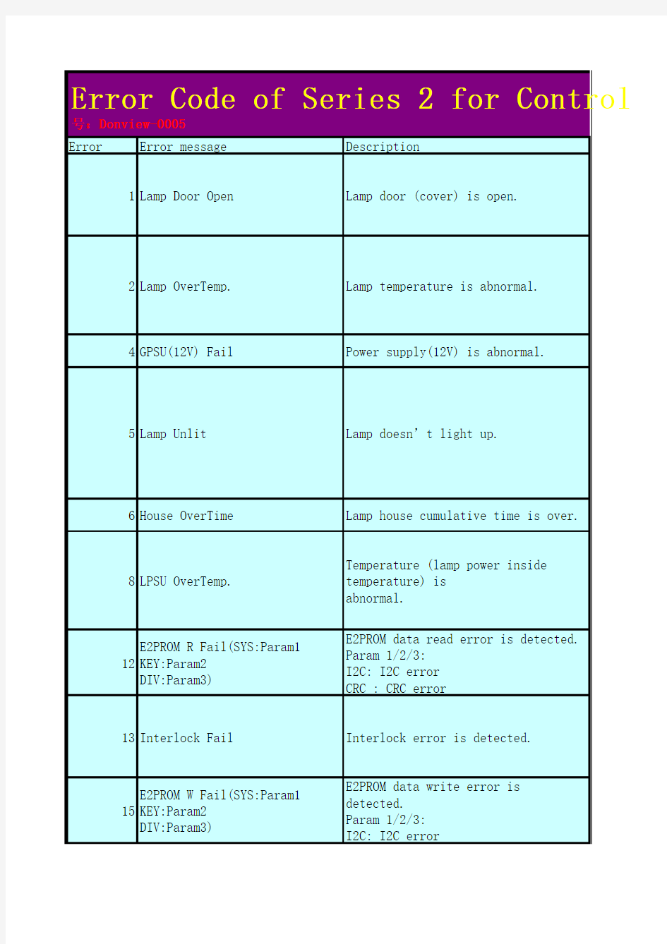
Error Error message Description
1Lamp Door Open Lamp door (cover) is open.
2Lamp https://www.doczj.com/doc/f3495457.html,mp temperature is abnormal.
4GPSU(12V) Fail Power supply(12V) is abnormal.
5Lamp Unlit Lamp doesn’t light up.
6House OverTime Lamp house cumulative time is over.
8LPSU OverTemp.Temperature (lamp power inside temperature) is
abnormal.
12E2PROM R Fail(SYS:Param1
KEY:Param2
DIV:Param3)
E2PROM data read error is detected.
Param 1/2/3:
I2C: I2C error
CRC : CRC error
13Interlock Fail Interlock error is detected.
15E2PROM W Fail(SYS:Param1
KEY:Param2
DIV:Param3)
E2PROM data write error is
detected.
Param 1/2/3:
I2C: I2C error
Error Code of Series 2 for Control 号:Donview-0005
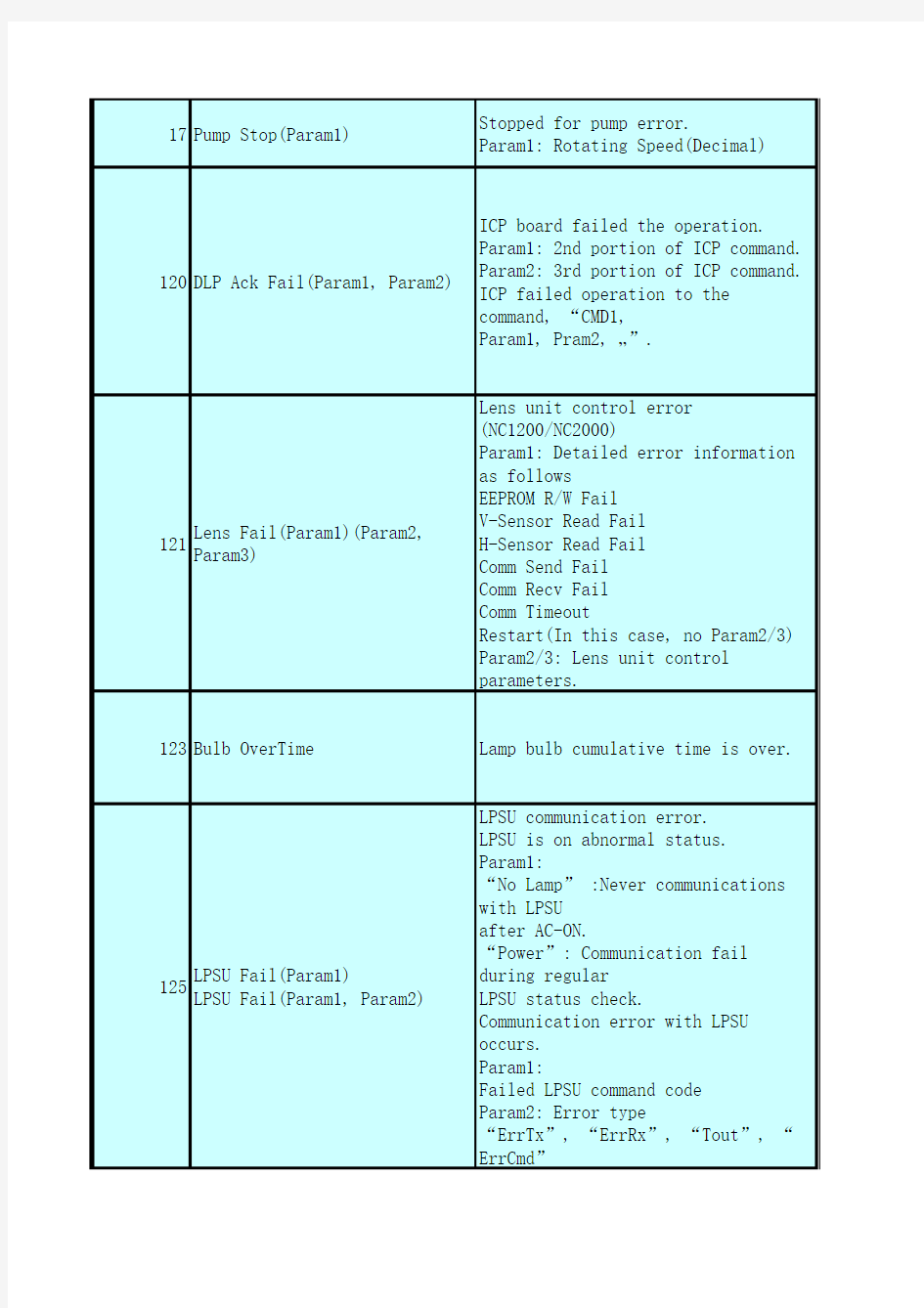
17Pump Stop(Param1)Stopped for pump error.
Param1: Rotating Speed(Decimal)
120DLP Ack Fail(Param1, Param2)ICP board failed the operation. Param1: 2nd portion of ICP command. Param2: 3rd portion of ICP command. ICP failed operation to the command, “CMD1,
Param1, Pram2, …”.
121Lens Fail(Param1)(Param2,
Param3)
Lens unit control error
(NC1200/NC2000)
Param1: Detailed error information
as follows
EEPROM R/W Fail
V-Sensor Read Fail
H-Sensor Read Fail
Comm Send Fail
Comm Recv Fail
Comm Timeout
Restart(In this case, no Param2/3)
Param2/3: Lens unit control
parameters.
123Bulb OverTime Lamp bulb cumulative time is over.
125LPSU Fail(Param1)
LPSU Fail(Param1, Param2)
LPSU communication error.
LPSU is on abnormal status.
Param1:
“No Lamp” :Never communications
with LPSU
after AC-ON.
“Power”: Communication fail
during regular
LPSU status check.
Communication error with LPSU
occurs.
Param1:
Failed LPSU command code
Param2: Error type
“ErrTx”, “ErrRx”, “Tout”, “
ErrCmd”
128OutRange(Param1, Param2,
Param3, Pram4)
Adjusting lamp output value has set
out of range.
Param1: Caused operation
Lamp M: Manual adjustment
Lamp D: Douser operation
Lamp FW: FeedBack(to keep watt)
process
Lamp FB: FeedBack(to keep
illuminance)
process
Lamp LM: Lamp memory process
Param2: Lamp current tried to set
by projector
(in 0.1A)
Param3: Lamp current get from LPSU
(in A)
Param4: Lamp wattage get from LPSU
(in W)
129Down Lamp Power(Param1,
Param2, Param3)
Down lamp power to decrease set
inside
temperature.
Param1: Measured point
(Out/Intake/Exhaust/DMD-B)
Param2: Temperature(in deg)
Param3: Lamp output
Lamp current (in 0.1A)
130MMS Comm
Fail(Param1:Param2:Param3)
MMS communication error is
detected.
Param1: Failed MMS command code
Param2: Error type (“Con”, “Tx
”, “Rx”, “Tout”)
Param3: Error code
131MMS Fan Stop Built-in MMS fan has stopped. 132MMS Fail Built-in MMS internal error.
133MM Reset (Command:Param1)Executed to reset Built-in MMS Param1: When executed to reset
Built-in MMS.
001: Executed to reset Built-in MMS when no
communications between projector main system and MMS.
T-001: Executed to reset Built-in MMS when no
communication between external projector and MMS.
140DLP CommR
Fail(Param1Param2Param3:Param
4)
Communication failure with the ICP
board.
(Communication I/F is RS-232C)
Param1: First portion of ICP
command.
Param2: Second portion of ICP
command.
Param3: Third portion of ICP
command.
Param4: Error type (“Con”, “Tx
”, Rxn”, “Nack”,
“Tout”)
e.g.) DLP CommR
Fail(010203:Nak=0001H)
ICP returns “NAK” response to the
command, “01,
02, 03, …”.
132MMS Fail Built-in MMS internal error.
141DLP CommE
Fail(Param1Param2Param3:Param
4)
Communication failure with the ICP
board.
(Communication I/F is Ethernet)
Param1: First portion of ICP
command.
Param2: Second portion of ICP
command.
Param3: Third portion of ICP
command.
Param4: Error type (“Con”, “Tx
”, Rxn”, “Nack”,
“Tout”)
e.g.) DLP CommR
Fail(010203:Nak=0001H)
ICP returns “NAK” response to the
command, “01,
02, 03, …”.
145SensorFail Outside
Air(Param1)
Sensor (Outside Air) read error.
Param1: Get/Set
Failed to get/set data from/to
sensor board.
146SensorFail LPSU
Intake(Param1)
Sensor (LPSU Intake) read error.
Param1: Get/Set
Failed to get/set data from/to
sensor board.
147SensorFail Exhaust(Param1)Sensor (Exhaust) read error. Param1: Get/Set
Failed to get/set data from/to sensor board.
148SensorFail DMD-B(Param1)Sensor (DMD-B) read error. Param1: Get/Set
Failed to get/set data from/to sensor board.
150Fan0 Stop(Param1) 151Fan1 Stop(Param1)
152Fan2 Stop(Param1) 153Fan3 Stop(Param1) 154Fan4 Stop(Param1) 155Fan5 Stop(Param1)Fan0 has stopped.
Param1: Rotating Speed(Decimal)
156Fan6 Stop(Param7)Fan0 has stopped.
Param1: Rotating Speed(Decimal)
157Fan7 Stop(Param8)
158Fan8 Stop(Param9)
159Fan9 Stop(Param10)
160GPSU Fan Stop GPSU Fan has stopped.
162Lamp Fan0 Stop(Param1)Lamp cooling fan0 has stopped. Param1: Rotating Speed (Decimal) or HW Prt
(Hardware protection)
165Lamp Fan1 Stop(Param1)Lamp cooling fan1 has stopped. Param1: Rotating Speed (Decimal) or HW Prt
(Hardware protection)
164ICP Fan Stop(Param1)ICP fan has stopped.
Param1: Rotating Speed(Decimal)
165GPI MACRO(n) Selection
Invalid
Selection of preset button (n)
through GPI is invalid
because metadata is enabled.
n: Preset Button Number(1-8)
166GPI Control(Param1) Invalid
Projector control through GPI is
invalid because
projector
is busy.
Param1: Canceled GPI control:
Lamp Off/ On , Mute Off/ On/
Power On/Off
Selection of preset button n (n=1
8)
170OverTemp.Outside Air(Param1)Set inside temperature (Outside Air) is abnormal.
Param1: Temperature(in deg) Fan7 has stopped. (Only for
NC3200S)
Param1: Rotating Speed(Decimal)
171OverTemp.Precaution(Param1)Set inside temperature(LPSU Intake) is close to over
temperature.
Param1: Precaution temperature(in deg)
172OverTemp.Exhaust(Param1)Set inside temperature (Exhaust) is abnormal.
Param1: Temperature(in deg)
173OverTemp.DMD-B(Param1)Set inside temperature (DMD-B) is abnormal.
Param1: Temperature(in deg)
174Bulb Entry No selection of current bulb.
177Tamper Fail(Param1)Service door tamper switch of projector is open.
Param1 : Location of tampering switch.
(Param1 is encrypted)
LCD: Decrypted while projector is service mode or
higher.
Log: Decrypted to view while DCC is service
mode or higher.
178Marriage Tamper Fail(Param1)Marriage tamper switch of projector is open.
Param1 : Location of tampering switch.
(Param1 is encrypted)
LCD: Decrypted while projector is service mode or
higher.
Log: Decrypted to view while DCC is service
mode or higher.
180CPU Fail(Mem) Param1:
Param2<->Param3
System Test Failed.(Memory)
Param1-3: Detailed Test results.
187GPSU(24V) Fail Power supply is abnormal.(24V)
201Error Log Write Fail Failed to store logs into projector system.
210Unknown LPSU Model(Param1)Unexpected LPSU is attached. Param1: Unexpected LPSU Product Model
211LPSU Fan Stop LPSU fan has stopped.
21312V Outside range(Param1)
12V supply is out of range.
Param1: Captured voltage value.
LCD: invalid
Log : valid
21424V Outside range(Param1)
24V supply is out of range.
Param1: Captured voltage value.
LCD: invalid
Log : valid
215Lamp Filter Time Over(Param1)The time to exchange lamp filter. (Future use)
Param1: usage hours
216Body Filter Time Over(Param1)The time to exchange body filter. (Future use)
Param1: usage hours
220AC On Fan Exchange Time The time to exchange Fan(AC On) 221Power On Fan Exchange Time The time to exchange Fan(Power On) 222Lamp Fan Exchange Time The time to exchange Lamp Fan
230Router Fail(Param1)Failed to control router.
Param1:
“Connect” : Failed to connect to router
“Tx” : Transmit error
“Rx” : Receive error
“Tout” : Communication timeout “Msg Format” : Unexpected data received
“Data”: No data to setup router “Verify”: Setting verify error
231SensorFail Opt Failed to control light sensor.
232MAC Write Fail Failed to setup MAC address of CPU
board.
233Illegal MAC Address Router WAN MAC address is illegal.
235Router Self Check Fail
(Param1, Param2, Param3)
Router health-check error.
Param1 : Health check error timing
“INIT”: After AC-ON
“STBY”: During standby
“ RUN”: During power-on
Param2: Health check result
“2”: Factory default
“3”: No responses(Dead lock or
something)
“4”: Unstable status
“5”: Factory default and unstable
status
“6”: Defective(possibly “2” to
“5”)
Param3: router response result
(Valid when Param2 is “4” and “5
”)
N of 4 ping responses
240SIB Comm
Fail(Param1Pram2Param3Param4)
Failed to communicate with SIB.
Param1:
“Connect”, “Tx”, “Rx”, “Nack
”, “Tout”
Param2: First portion of
SIBcommand.
Param3: Second portion of SIB
command.
Param4: Third portion of SIB
command.
When Param1 is “Nack”, nack data
is added after
Param4.
e.g.) SIB Comm
241SIB Error(Param1)SIB internal error.
Param1: SIB internal error status “FPGA Open”: Failed to open
serial I/F
“FPGA Tx:nnn”: FPGA send error (nnn: failed send command)
“FPGA Rx:nnn”: FPGA receive error (nnn: failed receive command)“MEM Open”: Device driver open error
“MEM Read”: Device driver read error
242SIB FPGA Reboot Executed to re-boot SIB FPGA for recovery.
246Fan11 Stop(Param1)Fan11 has Stopped (NC3240) 250Fan0 Stop Precaution(Param1)
251Fan1 Stop Precaution(Param1)
252Fan2 Stop Precaution(Param1)
253Fan3 Stop Precaution(Param1)
254Fan4 Stop Precaution(Param1)
255Fan5 Stop Precaution(Param1)
256Fan6 Stop Precaution(Param1)
257Fan7 Stop Precaution(Param1)
258Fan8 Stop Precaution(Param1)
259Fan9 Stop Precaution(Param1)
260Lamp Fan0 Stop
Precaution(Param1)
Lamp Fan0 Stop Precaution
Param1: Rotating Speed(Decimal)
261Lamp Fan1 Stop
Precaution(Param1)
Lamp Fan1 Stop Precaution
Param1: Rotating Speed(Decimal)
262Pump Stop Precaution(Param1)Pump Stop Precaution
Param1: Rotating Speed(Decimal)
Fan0~9 Stop Precaution
Param1: Rotating Speed(Decimal)
263ICP Fan Stop
Precaution(Param1)
ICP Fan Stop Precaution
265Fan11 Stop Precaution(Param1)Fan11 Stop Precaution (NC3240) Param1: Rotating Speed(Decimal)
270SD Tamper Terminate(Param1)Terminated service door tamper event latched by
Enigma
board.
LCD: Not supported
Log: Supported
271IMB:SD Tamper
Terminate(Param1)
Terminated service door tamper
event latched by
IMB.
LCD: Not supported
Log: Supported
280Bulb Warranty Over Bulb warranty time over 301System Error
302Self Test Error
303
Install Release Package Error
304Load Release Package Error
305Key Error
306Certificate Error
317ICP Normal Configuration
318ICP Boot Configuration Error
319FMT Normal Configuration Error
320FMT Boot Configuration Error
321FMT Satellite Configuration Error
322
1.20V Supply out of range 323
1.80V Supply out of range 324
2.50V Supply out of range 325
3.30V Regulator out of range
326ICP FPGA Temperature out of range
327FMT FPGA Temperature out of range
328ICP Flash Update Error
329FMT Sequence Data File Mismatch
330FMT DMD Data File Mismatch
331FMT Flash Checksum Error -Sequence Data
332FMT Flash Checksum Error -DMD Data
333Satellite Hardware Mismatch 334FMT Flash Update Error
335
Red Satellite Reports Reset
336Red Satellite Serial Link Error
337Red Satellite Firmware Configuration Error
338Red DAD1000 Bias Under Voltage Error
339Red DAD1000 Reset Under Voltage Error
340Red DAD1000 Offset Under Voltage Error
341Red DAD1000 Thermal Shutdown Error
342Green Satellite Reports Reset
343Green Satellite Serial Link Error
344Green Satellite Firmware Configuration Error
345Green DAD1000 Bias Under Voltage Error
346Green DAD1000 Reset Under
Voltage Error
ICP board error
347Green DAD1000 Offset Under Voltage Error
348Green DAD1000 Thermal Shutdown Error
349
Blue Satellite Reports Reset
350Blue Satellite Serial Link Error
351Blue Satellite Firmware Configuration Error
352Blue DAD1000 Bias Under Voltage Error
353Blue DAD1000 Reset Under Voltage Error
354Blue DAD1000 Offset Under Voltage Error
355Blue DAD1000 Thermal Shutdown Error
356RTC Error
400Enigma Comm
Fail(Param1Param2Param3:Param
4)
No communication with the Enigma
board.
Param1: First portion of Enigma
command.
Param2: Second portion of Enigma
command.
Param3: Third portion of Enigma
command.
Param4: Error Type
“Conn=x”, “Tx”, “Rxn”, “
Nack=xxxxH”,
“Tout=xxxx”
410System Error Enigma Status error
411Self Test Error
412
Install Release Package Error
413
Load Release Package Error
414
TI Login List Package Error
Enigma Status error
415Security Officer Login List Package Error
419
Certificate or Key Error 420
ICP Communications Status 426
User Loader Integrity Error
427Main Application Integrity Error
428RNG Hardware Integrity Error 429DRNG Algorithm Integrity
430
RSA Algorithm Integrity Error
431AES Algorithm Integrity Error 432HMAC Algorithm Integrity
433SHA Algorithm Integrity Error 434TLS Integrity Error
435FPGA Configuration Integrity Error
436FPGA CineLink 2 Decryption Integrity Error
437
RTC Error
442
FPGA Configuration Error
443FPGA Temperature out of range
446RNG Hardware Duplicate Output Error
447DRNG Algorithm Duplicate Output Error
4501.20V Supply out of range 4511.80V Supply out of range 4522.50V Supply out of range 4533.30V Regulator out of range
458SelfTest User Loader Integrity Error
459SelfTest Main Application Integrity Error
460SelfTest RNG Hardware Integrity Error
461SelfTest DRNG Algorithm Integrity Error
462SelfTest RSA Algorithm
Integrity Error Enigma Status error
Enigma Status error
Enigma is in FIPS error
state.(Integrity check error)
Enigma Status error
Enigma is in FIPS error
state.(Integrity check error)
463SelfTest AES Algorithm Integrity Error
464SelfTest HMAC Algorithm Integrity Error
465SelfTest SHA Algorithm Integrity Error
466
SelfTest TLS Integrity Error
467SelfTest FPGA Configuration Integrity Error
468SelfTest FPGA CineLink. 2 Decryption Integrity Error
474Security Tamper
475Top Side Security Enclosure Open
476Bottom Side Security Enclosure Open
477Security Battery Event Battery tamper condition exists.
478Software Commanded
Zeroization
Destroyed Enigma key by software
command.
481Security Enclosure Not Armed Enigma security not armed.
482Physical Marriage Tamper Latched physical marriage tamper condition on Enigma board
483Logical Marriage Tamper Logical marriage tamper condition exists.
484Marriage NOT Active Marriage has NOT been established (active).
486Service Door Tamper Latched service door tamper condition on Enigma board
487Security Log Error
Security log is full.
488Security Battery Low Warning Close to “Security Battery Low”. 489Security Log Warning Close to “Security Log Error”.
500IMB Comm Fail
(Param1Param2Param3:Param4)
No communication with the IMB.
510IMB:System Error
511IMB:Self Test Error
519IMB:Certificate or Key Error Enigma Status error
Security tamper condition exists. IMB Status error
520IMB:ICP Communications Status IMB fails to do logical marriage to ICP when IMB
powers
up. Because of no communications with ICP
during
537IMB RTC is “invalid”IMB RTC is “invalid”
543IMB:FPGA Temperature out of range
550IMB:Supply voltage out of range
574IMB:Security Tamper Security tamper condition exists in IMB
577IMB:Security Battery Even Battery tamper condition exists in IMB
581IMB:Security Enclosure Not
Armed
Security tamper condition exists in
IMB
582IMB:Physical Marriage Tamper Latched physical marriage tamper condition on
583IMB:Logical Marriage Tamper Logical marriage tamper condition exists in IMB
584IMB:Marriage NOT Active Marriage between ICP and IMB has NOT been
established (active).
586IMB:Service Door Tamper Latched service door tamper
condition on IMB
588IMB:Security Battery Low
Warning
Close to “(577) IMB: Security
Battery Event”
IMB Status error
trol Command list Rev3.0 文档编Checking point
1. Verify if the lamp door is closed and locked properly.
2. Is there any physical damage in the switch?
3. Check the connection between POCO on COVER PWB and POCN3 on
PJDIV
PWB.
1. Check the ambient temperature. It should be 35 degC or lower.
2. Check if there is any problem on suction air and exhaust air.
3. Check the air filter and verify that it is not clogged.
4. Check that the ventilation system is being operated within
required specification.
5. Check the connection between Thermostat and POCN5 on PJDIV PWB.
1. Check the DC power supply voltage.
2. Check the connection between GPSU and POPSM on PJDIV PWB.
1. Check if the current bulb usage time is over limit. If yes,
replace the bulb.
2. Check if there are loose screw connections on the igniter and
cathode cable on the
lamp holder.
3. Check if an electric blackout has occurred.
4. Check if the LPSU is turned on.
5. Check the connection between POCN2 on PJDIV PWB and PEDE-A PWB.
1. Replace the reflector and reset lamp (except for house) usage
hours.
1. Check the ambient temperature. It should be 35 degC or lower.
2. Check if there is any problem on suction air and exhaust air.
3. Check the air filter and verify that it is not clogged.
4. Check that the ventilation system is being operated within
required specification.
5. Replace the LPSU.
1. Check CPU PWB/ PJDIV PWB/KEY I/O PWB.
2. Check the cable between POIF on PJDIV PWB and KEY IO PWB.
1. Verify that external control is working properly.
2. Check the connection between POIL on PEDE-A PWB and INTER PWB.
3. Check the connection between POCI on PEDE-A PWB and POCN2 on
PJDIV
PWB.
1. Check CPU PWB/ PJDIV PWB/KEY I/O PWB.
2. Check the cable between POIF on PJDIV PWB and KEY IO PWB.
1. Check the connection between POCN5 on PJDIV PWB and the pump.
2. Check the 12v voltage to control the pump.
3. Check the coolant of the unit.
1. Check if the ICP version is the latest.
2. Launch the "Macro File Tools" to check if there are any problems with the ICP
configuration files.
3. Retry the projector operation.
4. Reset the ICP board and retry the projector operation.
5. Check the connection between FSB and MOTHER PWB.
6. Check the power supply voltage for the ICP board.
7. If new ICP board was installed, restore the setting data in icp cfg files in Relese
1. Check the connection between POCN2 on PJDIV PWB and MOTOR I/F PWB.
2. Replace the MOTOR I/F PWB.
1. Check the usage time of lamp bulb and replace the lamp bulb if needed.
2. Verify that New Entry Bulb Setting was set when the lamp bulb was replaced.
3. Replace CPU PWB.
LPSU Fail(No Lamp):
1. Check if the LPSU is powered on.
2. Check the connection of RS-232C cable between PEDE-A PWB and LPSU.
3. Check the connection between POCN2 on PJDIV PWB and PEDE-A PWB. LPSU Fail(Power):
1. Power-cycle the LPSU. If problem is not gone, replace the LPSU. LPSU Fail(Param1, Param2):
1. Check if the LPSU is powered on.
2. Check the connection of RS-232C cable between PEDE-A PWB and LPSU.
3. Check the connection between POCN2 on PJDIV PWB and PEDE-A PWB.
1. The requested lamp output adjustment is out of range.
1. Check the ambient temperature. It should be 35 degC or lower.
2. Check if there is any problem on suction air and exhaust air.
3. Check the air filter and verify that it is not clogged.
4. Check that the ventilation system is being operated within required specification.
1. Check the connection between MM3000B and Mother PWB.
2. Check LAN connectors and LAN cable.
3. Check that the projector is powered on, and not in stand-by mode.
1. Check fan cable connection.
2. Replace FAN.
In regard to MMS Fail, there are three types of errors as shown below.
The respective methods of taking measures are described below.
1) FPGA***
This is a configuration error of FPGA. If the associated FPGA is of an input
board, try to remount the board or check the flexible cable connections or
reinstall the FPGA data.
In the case of the other FPGA errors, also try to reinstall the FPGA data. If
this check is difficult to perform, replace the associated board completely.
2) Default Data
The data contained some deficiency at the time of shipment from the factory.
Reinstall the data.
3) User Data
This error is caused by a certain deficiency in the user data. Copy the user data into the PC so that further checks can be made. Execute a factory default to see if the default signal data eliminates the problem.
Since part of or all of the previously copied user data may have been corrupted,
reuse of these data is not recommended.
If the data is used for the purpose of setup data checks, they should be cleared later.
1. This message shows that the projector reset the MM3000B because of no response
messages.
If MMS Comm Fail occurs, see the MM3000B service manual.
1. If ICP is being updated by ICP & Enigma Control Program without "Special Mode",
this message will be shown.
2. If ICP is reset by ICP & Enigma Control Program, this message will be shown.
3. Retry the projector operation.
4. Reset the ICP board and retry the projector operation.
5. Check the connection between FSB and MOTHER PWB.
6. Check the power supply voltage for the ICP board.