V oltage-Source PWM Recti?er–Inverter Based on Direct Power Control and Its Operation
Characteristics
Akira Sato,Member,IEEE,and Toshihiko Noguchi,Senior Member,IEEE
Abstract—This paper describes a novel control strategy of di-rect power-control-based voltage-source pulsewidth modulation (PWM)recti?er–inverter.The key of this strategy is direct selec-tion of a switching state of the PWM recti?er–inverter on basis of instantaneous power errors.A relationship between the instanta-neous power and the switching state of the PWM recti?er–inverter is theoretically analyzed,which is essential to compose a switching-state table.Effectiveness of the proposed technique is examined through several experimental tests,using a1.6-kW prototype.As a result,unity power factor operation is achieved by the proposed method,and the output currents are con?rmed to be sinusoidal waveforms without large distortion under balanced and unbal-anced power-source condition.
Index Terms—Direct power control(DPC),nonlinear con-trol,smoothing capacitor,switching-state table,voltage-source pulsewidth modulation(PWM)recti?er–inverter.
I.I NTRODUCTION
I N general,ac–dc–ac conversion system is extensively used
in a variety of power system applications,industry applica-tions,transportation systems,etc.The ac–dc–ac conversion sys-tem is normally composed of a pulsewidth modulation(PWM) recti?er–inverter system,which requires an energy-buffering device,such as electrolytic capacitor to smooth dc-bus volt-age.Therefore,double-stage power conversion prevents physi-cal size reduction and longer product life of the whole apparatus. In recent years,a direct ac–ac power conversion system,such as matrix converter has attracted great attention and researchers have published a numerous number of papers on the direct ac–ac power conversion[1]–[7].On the other hand,a variety of con-trol techniques of reducing the energy-buffering device of the PWM converters have been proposed in the earlier studies[8]–[12].Feed-forward block of the output active power is adopted to the dc-bus-voltage control loop of the PWM recti?er in a number of proposed methods.The input current commands are calculated according to these control block,and is controlled by proportional–integral(PI)regulator,hysteresis comparator,etc. in stationary reference frame or rotating reference frame.There-
Manuscript received December17,2009;revised March15,2010,May 29,2010,and August28,2010;accepted September30,2010.Date of current version June29,2011.Recommended for publication by Associate Editor J.R. Espinoza.
A.Sato is with the Nagaoka University of Technology,Nagaoka940-2188, Japan(e-mail:asato@mem.iee.or.jp).
T.Noguchi is with the Shizuoka University,Hamamatsu432-8561,Japan (e-mail:ttnogut@ipc.shizuoka.ac.jp).
Digital Object Identi?er10.1109/TPEL.2010.2086488fore,in order to accomplished a minimization of the smoothing capacitor of the PWM converter,these control techniques lead to complicated system.
A number of new control techniques have been proposed to improve the control of the PWM converters with regard to the integration of control and modulation functions,alternate modu-lation schemes,and the sensorless method.The former schemes have the advantage of faster transient response and the pos-sibility of controlling simultaneously more than one variable. As one of these techniques,the authors have proposed a direct torque control(DTC)of the induction motor,which is relay (bang-bang)control of the torque and the?ux by two hysteresis comparators and a switching-state table[13].As a similar con-trol method of DTC algorithm,the authors originally reported a direct power control(DPC)of the voltage-source PWM recti?er in1997IEEE IAS Annual Meeting.In DPC strategy,the instan-taneous active and reactive powers are directly controlled in a manner analogous to torque and?ux control in the induction motor[14].The key features of this method are as follows:
1)no need to implement current minor loops;
2)no need for rotational coordinate transformation;
3)no need to separate PWM modulation block. Therefore,this strategy allows an ultimate high-speed power control response and simple con?guration of the power control system.From these,DPC-based technique has recently attracted signi?cant attention and researchers have explored[15]–[23]. One of the disadvantages of the DPC is variable switching fre-quency[17].In order to solve this problem,space vector mod-ulation(SVM)is adopted to the DPC system[18],[23],and DPC technique using the predictive control scheme has been proposed[22].Furthermore,the DPC techniques are extended to various power conversion systems,such as the wound rotor con?guration[15],the active power?lter[19],and the neutral-point-clamped converter[20],[21].
The authors have intensively been investigating the DPC strat-egy of three-phase power converters and its application to vari-ous power conversion systems,such as the voltage-source PWM recti?er,the current-source PWM recti?er,the multilevel PWM recti?er,and the voltage-source PWM inverter with LC?lters [24]–[26].
This paper presents a novel DPC strategy applied to the ac–dc–ac conversion system,which is composed of the voltage-source PWM recti?er and the voltage-source PWM inverter system with a very small dc-bus capacitor.Particularly,a the-oretical analysis of the relationship between a behavior of the instantaneous active and reactive power and the switching states
0885-8993/$26.00?2011IEEE
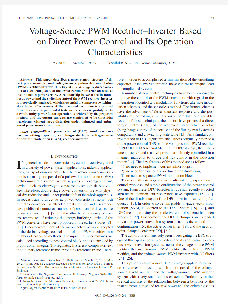
Fig.1.Simpli?ed circuit diagram of voltage-source PWM recti?er–inverter. of the PWM recti?er–inverter are focused on,which is an es-sential component to compose a switching-state table in the DPC algorithm.The validity of the proposed technique is ex-amined through experimental tests,using1.6-kW prototype. Consequently,excellent operation characteristics are con?rmed not only in a steady state but also in a transient state.Further-more,operation characteristic under an unbalance power-source condition is also con?rmed.
II.B ASIC P RINCIPLE
A main circuit of the ac–dc–ac converter,which consists of the voltage-source PWM recti?er and the voltage-source PWM inverter with a dc-bus capacitor,is shown in Fig.1,where v r,v s, and v t are the input voltages from a three-phase utility power source,V dc is the dc-bus voltage,and v u,v v,and v w are the output voltages to the load.In the PWM recti?er–inverter,the input active power p rec must be equal to a total of the output active power of the inverter p inv and a time derivative of the energy stored in the dc-bus capacitor p dc.Therefore,it can be expressed as follows:
p rec=p inv+p dc(1) where the main circuit losses of the power converters are ne-glected.The dc-bus capacitor C dc stores an electrostatic energy
of W dc=C d c V2
dc /2.The time derivative of the energy stored
in the dc-bus capacitor p dc is given by
p dc=d
dt
W dc=V dc C dc
dV dc
dt
.(2)
On the other hand,the reactive power of input front end
q rec and the reactive power of output q inv are independent of
each other because the two-stage power conversion system is
separated by the dc-bus,if the time derivative of the dc-bus
energy is small.
In order to achieve sinusoidal input current waveforms in the
case of balanced input voltages,the active and reactive power of
input must be constant.If the inverter controls so that the input
active power p rec may correspond to the output active power
p inv,(1)can be approximated as follows:
p rec≈p inv.(3) From(3),the smoothing capacitor is unnecessary because
power?owing through the dc bus is constant,which makes
p dc≈0,as presented in(2).In other words,a time derivative of the energy stored in the dc-bus capacitor p dc at nearly zero
value can be obtained by reducing the dc-bus capacitor,even
though the dc-bus voltage is?uctuated;hence,all the recti?er has to do is only the input reactive power control because the ac-tive power is determined by the load via the inverter.Therefore, the recti?er controls the reactive power of the input and the in-verter controls the active and reactive power of the output,which leads to the minimization of the smoothing capacitor across the dc bus.
In general,the PWM recti?er is required to obtain a stable voltage fed to a load,and to improve input power factor at the same time.In other words,the PWM recti?er requires two degrees of freedom(DOFs),that is,controlling dc-bus voltage and the reactive power of the input.For this reason,at least two legs need to perform PWM operation in a conventional PWM recti?er.On the other hand,the proposed method-based PWM recti?er needs to control only1DOF,which controls the reactive power of the input.Consequently,the proposed strategy operates a PWM control to only one leg of the three phase legs.
III.C ONTROL M ETHOD
A.System Con?guration
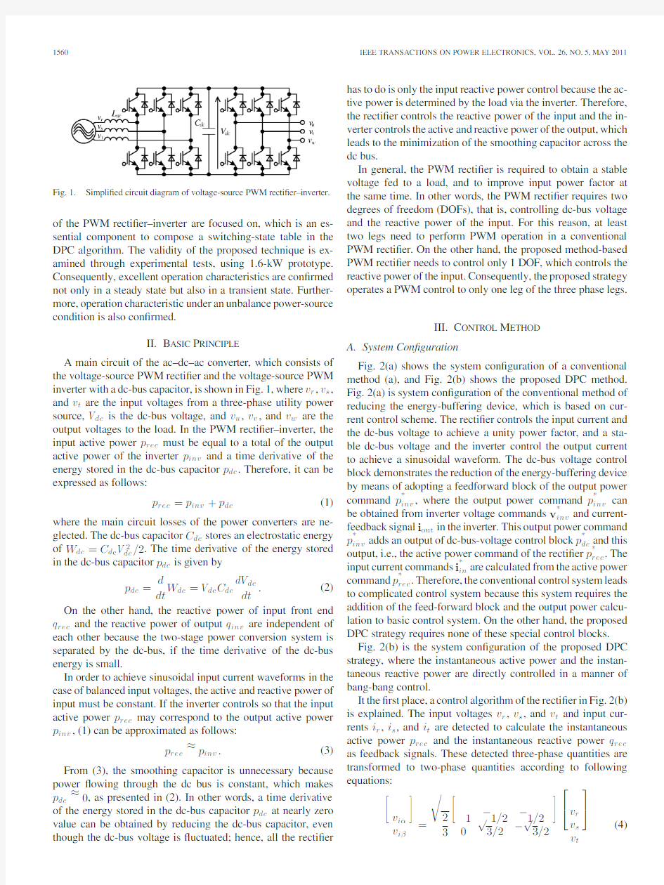
Fig.2(a)shows the system con?guration of a conventional method(a),and Fig.2(b)shows the proposed DPC method. Fig.2(a)is system con?guration of the conventional method of reducing the energy-buffering device,which is based on cur-rent control scheme.The recti?er controls the input current and the dc-bus voltage to achieve a unity power factor,and a sta-ble dc-bus voltage and the inverter control the output current to achieve a sinusoidal waveform.The dc-bus voltage control block demonstrates the reduction of the energy-buffering device by means of adopting a feedforward block of the output power command p?inv,where the output power command p?inv can be obtained from inverter voltage commands v?inv and current-feedback signal i out in the inverter.This output power command p?inv adds an output of dc-bus-voltage control block p?
dc
and this output,i.e.,the active power command of the recti?er p?rec.The input current commands i?in are calculated from the active power command p?rec.Therefore,the conventional control system leads to complicated control system because this system requires the addition of the feed-forward block and the output power calcu-lation to basic control system.On the other hand,the proposed DPC strategy requires none of these special control blocks. Fig.2(b)is the system con?guration of the proposed DPC strategy,where the instantaneous active power and the instan-taneous reactive power are directly controlled in a manner of bang-bang control.
It the?rst place,a control algorithm of the recti?er in Fig.2(b) is explained.The input voltages v r,v s,and v t and input cur-rents i r,i s,and i t are detected to calculate the instantaneous active power p rec and the instantaneous reactive power q rec as feedback signals.These detected three-phase quantities are transformed to two-phase quantities according to following equations:
v iα
v iβ
=
2
3
1?1/2?1/2
√
3/2?
√
3/2
?
?
v r
v s
v t
?
?(4)
SATO AND NOGUCHI:VOLTAGE-SOURCE PWM RECTIFIER–INVERTER BASED ON DPC AND ITS OPERATION CHARACTERISTICS
1561
Fig.2.System con?gurations of control method for PWM recti?er–inverter.(a)System con?gurations of conventional method.(b)System con?guration of the DPC method.
i iαi iβ
=
2
3
1?1/2?1/2
√
3/2?
√
3/2
?
?
i r
i s
i t
?
?.(5)
p rec and q rec are calculated by an inner product and an outer product between the voltage and current vectors,as shown in the following equation,respectively.
p rec q rec
=
v iαv iβ
v iβ?v iα
i iα
i iβ
.(6)
On the other hand,the instantaneous reactive power command q?rec is given from an outside of the system to control the total power factor.If a unity total power factor is required,q?rec must be set at zero.The control error of the reactive power,i.e.,Δq rec=q?rec?q rec,is quantized to generate digital signals S rq with a hysteresis comparator.In addition,a phase angle of the input voltage vector is spatially quantized to six sectorsΘr n by 60?by using several comparators.The quantized sectorsΘr n is mathematically expressed as
(n?2)
π
3
≤Θr n<(n?1)π
3
∵n=1,2,...,6.(7) An appropriate switching state of the recti?er can be deter-mined by a combination of these quantized signals S rq and Θr n.The calculated instantaneous active power p rec is pro-vided to the inverter control block.
On the other hand,the inverter is controlled as follows.The in-stantaneous active power command p?inv and the instantaneous reactive power command q?inv are provided from the output-current-control block,where the output-current control is im-plemented by using the proportional regulator in stationary co-ordinates in order to examine operation characteristics of the
1562IEEE TRANSACTIONS ON POWER ELECTRONICS,VOL.26,NO.5,MAY2011 proposed DPC strategy.The detected output currents i u,i v,and
i w are transformed to two-phase output currents i oαand i oβ
according to the following equation:
i oαi oβ
=
2
3
1?1/2?1/2
√
3/2?
√
3/2
?
?
i u
i v
i w
?
?.(8)
The sinusoidal two-phase output current command i?oαand
i?oβare compared with their calculated values i oαand i oβ,re-
spectively.The control errors between them are delivered to proportional current regulators,and their outputs are the in-
verter output voltage commands v?oαand v?
oβ.p?inv and q?inv can
easily obtain with(9)by using the aforementioned v iα,v iβ,i iα, and i iβ,respectively
p?inv q?inv
=
v?oαv?
oβ
v?
oβ
?v?oα
i oα
i oβ
.(9)
The control error of the active power,i.e.,Δp inv=p?inv?p rec,and the instantaneous reactive power command q?inv are used to generate quantized signals S ip and S iq with hysteresis comparators.S ip and S iq correspond to either an ascent mode or a descent mode of the instantaneous power,according to the digital values“1”or“0”.Furthermore,the output current command vector i?o is also quantized to six sectorsΘi n. These digital signals S ip,S iq,andΘi n are used to select the most appropriate switching states of the inverter and to control ON/OFF of each leg.In other words,a combination of S ip,S iq, andΘi n determines the next unique and optimum switching state of the inverter.
https://www.doczj.com/doc/e616392401.html,posing Switching Table
The proposed DPC strategy is,in principle,based on bang-bang control technique of the instantaneous active and reactive power.It is important to investigate the relationship between the switching state of the PWM recti?er–inverter and the polarities of time derivative of the active and reactive power dp/dt and dq/dt in a speci?edΘn.The polarities of dp/dt and dq/dt cor-respond to“1”or“0”of quantized signals S p and S q.According to the time derivatives dp/dt and dq/dt,mathematically solved in term of the switching state of the PWM recti?er–inverter, one of the switching states of the PWM recti?er–inverter must uniquely be determined to restrict the control errors of the active and reactive powerΔp andΔq within the hysteresis bands.
In the following discussion,the time derivatives dp/dt and dq/dt in an exceedingly short time duration,which corresponds to a moment of switching operation,such as several kilohertz operation in the PWM recti?er–inverter,are theoretically inves-tigated.
The time derivative of the reactive power in the recti?er dq rec/dt is derived by using a mathematical model of the recti-?er indicated in Fig.3(a).From this model,the current equation can be written as
L d i in
dt
=v in?v rec.
(10)
Fig.3.Mathematical model of PWM recti?er–inverter.(a)Recti?er model.
(b)Inverter model.
The output voltage vector of the recti?er v rec is de?ned by
the following equation,where V dc is dc-bus voltage:
v rec=
2
3
V dc(S r+S s e j2π/3+S t e j4π/3).(11)
The input voltage vector v in can be expressed as a rotating
vector as follows:
v in=
√
3V inrms e jθi n(12)
where V inrms is a root-mean-square value of the input line volt-
age.
In an exceedingly short time duration like a switching interval
of the PWM recti?er,a variation of the input voltage vector v in is
negligibly small;hence,v in can approximately be considered
to be a constant value.Therefore,the time derivative of the
reactive power in the recti?er dq rec/dt delivered from(6)can
be approximated as follows:
dq rec
dt
=
d v in
dt
×i in+v in×d i in
dt
≈v in×d i in
dt
.(13)
Substituting((10))–((12))into(13),dq rec/dt is solved as
follows:
dq rec
dt
=
√
2V inrms V dc
L
(S r2cosθin?S r1sinθin)(14)
∵S r1=S r?1
2
S s?
1
2
S t S r2=
√
3
2
S s?
√
3
2
S t
whereθin is an argument of the input line voltage vector v in.
Similarly,the time derivatives of the active and reactive power
in the inverter dp inv/dt and dq inv/dt are delivered by using a
mathematical model of the inverter indicated Fig.3(b).From
this model,the following circuit equation is given:
d i out
dt
=
v inv?v e
L
.(15)
SATO AND NOGUCHI:VOLTAGE-SOURCE PWM RECTIFIER–INVERTER BASED ON DPC AND ITS OPERATION CHARACTERISTICS
1563
Fig.4.Calculation results of dq r e c /dt ,dp in v /dt ,and dq in v /dt in Θ1.(a)Calculation results of dq r e c /dt .(b)Calculation results of dp in v /dt and dq in v /dt .
A back electromotive force vector v e is expressed,as a rotating,with an amplitude of √3V e rms and a frequency of ω>,i.e.,
v e =√
3V e rms e j θo u t (16)where θout is an argument of the output current vector i out .
The output voltage vector v inv of the inverter is a function of the switching state as expressed in (17);therefore,
v inv = 2
3V dc (S u +S v e j 2π/3+S w e j 4π/3).(17)A combination of the inverter and an inductance in the current controlled inverter is regarded as a current source;hence,the model of the inverter indicated in Fig.3(b)can be considered the current-source-voltage load.
Since a variation of a back electromotive force vector v e is negligibly small in a short time duration,such as a PWM pulse interval,v e can nearly be regarded as a constant value.Consequently,the time derivatives of the active and reactive power dp inv /dt and dq inv /dt are delivered from (9)as follows:
dp inv dt =d i out dt ·v e +i out ·d v e
dt ≈d i out dt
·v e (18)
TABLE I
S WITCHING -STATE TABLE OF RECTIFIER
.
TABLE II
S WITCHING -STATE TABLE OF INVERTER
.
dq inv dt =d i out dt ×v e +i out ×d v e dt ≈d i out dt
×v e .(19)Substituting ((15))–((17))into (18)and (19),dp inv /dt and dq inv /dt are solved as follows:
dp inv dt =V e rms
L
{?3V e rms +√2V dc (S i 1cos θout +S i 2sin θout )}(20)
dq inv
dt
=√
2V e rms V dc
L
(S i 2cos θout ?S i 1sin θout )(21)
S i 1=S u ?12S v ?1
2S w S i 2=
√32S v ?√
32
S w .Since dq rec /dt ,dp inv /dt ,and dq inv /dt are calculated from (14),(20),and (21),respectively,ascent or descent of the instan-taneous active and reactive power can be found in connection with the switching state of the PWM recti?er–inverter.Fig.4il-lustrates an example of the increasing and decreasing behaviors of the instantaneous power in the sectors Θr 1and Θi 1.The optimum voltage vector of the PWM recti?er–inverter can be selected directly from this illustration.Suppose that one of the voltage vector of the inverter is selected to increase the active power (S ip =“1”)and decrease the reactive power (S iq =“1”),for example.There are two possible voltage vectors v i 1and v i 5in this situation.Selecting one of two vectors can be done by de-termining adjacent output current vector to i ?out ,that is,v i 5.The switching-state table of the PWM recti?er–inverter is composed on the basis of the aforementioned discussion,as indicated in Tables I and II.
IV .E XPERIMENTAL R ESULTS
In order to examine operation characteristics of the proposed DPC-based control of the PWM recti?er–inverter,a 1.6-kW prototype was developed,which constitutes analog and digital mixed signal hardware.Electric parameters of the power circuit are listed in Table III.
1564IEEE TRANSACTIONS ON POWER ELECTRONICS,VOL.26,NO.5,MAY
2011
Fig.5.Operation waveforms and frequency spectrum of input current un-der balanced power-source condition.(a)Operation waveforms.(b)Frequency spectrum of input current.
TABLE III
E LECTRIC PARAMETERS O
F MAIN
CIRCUIT
A.Operation Waveforms in Steady State
Fig.5represents several operation waveforms of the proto-type in the steady state,where the load is 1.4kW and average switching frequency of the recti?er and the inverter f rsw and f isw are 8.6kHz and 6.7kHz,respectively.As can be seen,the input current has a sinusoidal waveform similar to the voltage waveform.This unity power factor operation is achieved by giv-ing zero reactive power command.The proposed DPC system makes the line current waveform sinusoidal,although the cur-rent is never directly controlled to be sinusoidal with
current
Fig.6.Output current command step response.(a)operation waveforms.(b)operation waveforms around T in
(a).
Fig.7.
Disturbance step response.
minor loops.On the other hand,the output current waveform is controlled to be sinusoidal waveforms with no large distortion.Furthermore,the dc-bus voltage waveform has a three-phase bridge-recti?ed waveform,which is varied at 300Hz,because the proposed strategy operates so that the maximum and mini-mum phases are in ON state,and the medium phase is pulsewidth modulated.
Fig.6shows a transient response when the output current is changed stepwise between 6.3and 7.5A.As can be seen here,it can be observed that the response time is approximately 0.5ms and excellent transient waveforms are observed without an overshoot,even in this transient state.Fig.7is another transient that shows waveforms in a load step change between 0.92and 1.4kW.The output current is kept almost constant at the com-manded value,even though the sudden load change is applied.As demonstrated in these experimental tests,the DPC system of the PWM recti?er–inverter,which is based on bang-bang con-trol of the instantaneous active and reactive power,functions
SATO AND NOGUCHI:VOLTAGE-SOURCE PWM RECTIFIER–INVERTER BASED ON DPC AND ITS OPERATION CHARACTERISTICS
1565
Fig.8.Total
ef?ciency.
Fig.9.Total input power
factor.
Fig.10.
Total harmonic distortion of input current.
quite effectively to achieve a unity power factor operation,to reduce harmonics of the input current,and to obtain the quick responses in regulating the output current.
Figs.8and 9show total ef?ciency and total input power fac-tor of the DPC-based prototype,respectively.Total harmonic distortion is depicted in Fig.10to evaluate quality of the input current waveform.The maximum total input power factor is 99.9%,the maximum total ef?ciency is 95.5%,and total har-monic distortion of the input current is 4.7%at 1.6-kW load.The total input power factor and the total ef?ciency get worse as less load is applied,as shown in Figs.8and 9.This is due to the input current distortion as indicated in Fig.10.Hysteresis bandwidths for the instantaneous active and reactive power in the DPC system are not changed in accordance with the load;thus,the input line currents relatively include more ripples as the load becomes
lighter.
Fig.11.Operation waveforms under unbalanced power-source condition.
B.Operation Characteristics Under Unbalanced Power-Source Condition
Assuming unbalanced power-source condition,operation characteristics of the proposed system are experimentally exam-ined.The unbalanced power-source voltages are v rs =200V ,v st =187V ,and v tr =173V (unbalance ratio is 7.32%),while other test conditions were exactly same as those of Table III.
Fig.11shows the operation waveforms of the PWM recti?er–inverter when the load is 1.2kW and the fast Fourier transform (FFT)analysis results of the input and output currents are in-dicated in Fig.12.As can be seen in Fig.11,the input current waveforms are distorted,but the output current waveforms are well regulated at commanded value without low-frequency large ripples.
The DPC-based PWM recti?er–inverter operates so that the input active power may correspond to the output active power.Therefore,the DPC system carries out to transfer more ac-tive power from ac power-source to load,when the load side goes down,and vice versa .Consequently,the input current waveforms are distorted due to the inclusion of third harmon-ics,which is reluctantly necessary to cancel out the second
1566IEEE TRANSACTIONS ON POWER ELECTRONICS,VOL.26,NO.5,MAY
2011
Fig.12.FFT analysis results of input and output currents under unbalanced power-source condition.
harmonics caused by the unbalanced power-source voltages. However,the output currents are stable sinusoidal waveforms with no large distortion.The active and reactive powers of the output are not affected by power-source condition.Therefore, the active and reactive power commands p?inv and q?inv are dc quantities irrespective of the unbalanced power-source condi-tion.As a result,the output currents are controlled to be low distortion and balanced.
From the aforementioned discussion,the proposed DPC strat-egy gives priority to the output control,which is the most sig-ni?cant feature of the DPC system.
V.C ONCLUSION
This paper proposed a novel control strategy of a voltage-source PWM recti?er–inverter with a very small bus capacitor, which features direct control of the instantaneous active and reactive power.The key of this strategy is bang-bang control of the power by means of appropriate selection of the switch-ing state of the PWM recti?er–inverter.In theoretical analysis of the proposed strategy,a relationship between the switching state of the PWM recti?er–inverter and the instantaneous active and reactive power is clari?ed,which leads to composition of the appropriate switching state table in the controller.In addi-tion,feasibility of the proposed system was examined through experimental tests,using a1.6-kW prototype.A result of the test,the proposed system makes it possible to obtain a unity total power factor by setting reactive power command at zero,and low distorted current waveforms are con?rmed.In addi-tion,high-speed response and excellent stability of the output currents are con?rmed in a transient response. Furthermore,operation characteristics under unbalanced power-source condition were experimentally investigated.The proposed DPC technique is capable of regulating the stability of output current suf?ciently without special compensation block, although the power-source voltages are unbalanced.This is the unique feature of the proposed DPC strategy.Future works are the establishment of the optimization design method for the proposed DPC system,such as the parameters of the main cir-cuit and the hysteresis bandwidth,and the improvement of total harmonic distortion in all range.
R EFERENCES
[1]P.W.Wheeler,J.Rodrigues,J.C.Clare,L.Empringham,and A.Weinstein,
“Matrix converters:A technology review,”IEEE Trans.Ind.Electron., vol.49,no.2,pp.276–288,Apr.2002.
[2]L.Wei,T.A.Lipo,and H.Chan,“Matrix converter topologies with re-
duced number of switches,”in Proc.PESC’02,Cairns,Australia,pp.57–
63.
[3]J.Itoh,I.Sato,A.Odaka,H.Ohguchi,H.Kodachi,and N.Eguchi,“A
novel approach to practical matrix converter motor drive system with reverse blocking IGBT,”IEEE Trans.Power Electron.,vol.20,no.6, pp.1356–1363,Nov.2005.
[4] C.Klumpner,F.Blaabjerg,I.Boldea,and P.Nielsen,“New modulation
method for matrix converters,”IEEE Trans Ind.Appl.,vol.42,no.3, pp.797–806,May/Jun.2006.
[5]J.W.Kolar,F.Schafmeister,S.D.Round,and H.Ert,“Novel three-phase
AC-AC sparse matrix converters,”IEEE Trans.Power Electron.,vol.22, no.5,pp.1649–1661,Sep.2007.
[6]T.Wijekoon,C.Klumpner,P.Zanchetta,and P.W.Wheeler,“Imple-
mentation of a hybrid AC–AC direct power converter with unity voltage transfer,”IEEE Trans.Power Electron.,vol.23,no.4,pp.1918–1926, Jul.2008.
[7]P.C.Loh,R.Rong,F.Blaabjerg,and P.Wang,“Digital carrier modulation
and sampling issues of matrix converters,”IEEE Trans.Power Electron., vol.24,no.7,pp.1690–1700,Jul.2009.
[8]S.Ogasawara,N.Yamagishi,H.Totsuka,and H.Akagi,“A voltage
source PWM recti?er-inverter with feed-forward control of instantaneous power,”IEEJ Trans.Ind.Appl.,vol.111,no.11,pp.937–944,Nov.
1991.
[9]L.Malesani,L.Rossetto,P.Tenti,and P.Tomasin,“AC/DC/AC PWM
converter with reduced Energy Storage in the DC Link,”IEEE Trans.
Ind.Appl.,vol.31,no.2,pp.287–292,Mar./Apr.1995.
[10]J.Jung,S.Lim,and K.Nam,“A feedback linearizing control scheme
for a PWM converter-inverter having a very small DC-link capaci-tor,”IEEE Trans.Ind.Appl.,vol.35,no.5,pp.1124–1131,Sep./Oct.
1999.
[11] D.Lee,G.Lee,and K.Lee,“DC-bus voltage control of three-phase AC/DC
PWM converter using feedback linearization,”IEEE Trans.Ind.Appl., vol.36,no.3,pp.826–833,May/Jun.2000.
[12]N.Hur,J.Jung,and K.Nam,“A fast dynamic DC-link power-balancing
scheme for a PWM converter-inverter system,”IEEE Trans.Ind.Elec-tron.,vol.48,no.4,pp.794–803,Aug.2001.
[13]I.Takahashi and T.Noguchi,“A new quick-response and high-ef?ciency
control strategy of an induction motor,”IEEE Trans.Ind.Appl.,vol.22, no.5,pp.820–827,Sep.1986.
[14]T.Noguchi,H.Tomiki,S.Kondo,and I.Takahashi,“Direct power control
of PWM converter without power-source-voltage sensors,”IEEE Trans.
Ind.Appl.,vol.34,no.3,pp.473–479,May/Jun.1998.
[15]R.Datta and V.T.Ranganathan,“Direct power control of grid-connected
wound rotor induction machine without rotor position sensors,”IEEE Trans.Power Electron.,vol.16,no.3,pp.390–399,May2001.
[16]M.Malinowski,M.P.Kazmierkowski,S.Hansen,F.Blaabjerg,and
G.D.Marques,“Virtual-?ux-based direct power control of PWM rec-
ti?ers,”IEEE Trans.Ind.Appl.,vol.37,no.4,pp.1019–1027,Jul./Aug.
2001.
[17]M.Malinowski,M.P.Kazmierkowski,and A.M.Trzynadlowski,“A com-
parative study of control techniques for PWM recti?ers in AC adjustable
SATO AND NOGUCHI:VOLTAGE-SOURCE PWM RECTIFIER–INVERTER BASED ON DPC AND ITS OPERATION CHARACTERISTICS1567
speed dives,”IEEE Trans.Power Electron.,vol.18,no.6,pp.1390–1396, Nov.2003.
[18]M.Malinowski,M.Jasinski,and M.P.Kazmierkowski,“Simple direct
power control of three-phase PWM recti?er using space-vector modulation (DPC-SVM),”IEEE Trans.Ind.Electron.,vol.51,no.2,pp.447–454, Apr.2004.
[19]M.Cichowlas,M.Malinowski,M.P.Kazmierkowski,D.Sobczuk,P.
Rodriguez,and J.Pou,“Active?ltering function of three-phase PWM boost recti?er under different line voltage conditions,”IEEE Trans.Ind.
Electron.,vol.52,no.2,pp.410–419,Apr.2005.
[20]M.Malinowski,W.Kolomyjski,M.P.Kazmierkowski,and S.Stynski,
“Advanced DSP control of3-level DC/AC converter for variable-speed PMSG,”in Proc.EPE-PEMC’06,Portoroz,Slovenia,Aug.2006,pp.889–894.
[21]L.A.Serpa and J.W.Kolar,“Virtual-?ux direct power control for mains
connected three-level NPC inverter systems,”in Proc.PCC’07,Nagoya, Japan,Apr.,pp.130–136.
[22]P.Cort′e s,J.Rodr′?guez,P.Antoniewicz,and M.P.Kazmierkowski,“Direct
power control of an AFE using predictive control,”IEEE Trans.Power Electron.,vol.23,no.5,pp.2516–2523,Sep.2008.
[23]J.Restrepo,J.Aller,J.Viola,A.Bueno,and T.Habetler,“Optimum space
vector computation technique for direct power control,”IEEE Trans.
Power Electron.,vol.24,no.2,pp.1637–1645,Jun.2009.
[24]T.Noguchi,A.Sato,and D.Takeuchi,“Minimization of DC reactor
and operation characteristics of direct-power controlled current-source PWM recti?er,”in Proc.IEEE.IECON’06,Paris,France,Nov.,pp.2787–2792.
[25] A.Sato and T.Noguchi,“Multi-level current-source PWM recti?er based
on direct power control,”in Proc.IECON’07,Taipei,Taiwan,Nov., pp.1768–1773.
[26] A.Sato and T.Noguchi,“Novel control strategy of instantaneous power
based CVCF inverter,”in Proc.PEDS’07,Bangkok,Thailand,Nov., pp.
1502–1507.
Akira Sato(M’05)was born in Daisen,Japan,in
1979.He received the B.Eng.degree in production
systems engineering from Akita National College
of Technology,Akita,Japan,the M.Eng.degree in
electrical and electronics systems engineering from
Nagaoka University of Technology,Nagaoka,Japan,
and D.Eng.degree in energy and environment en-
gineering from Nagaoka University of Technology,
Nagaoka,Japan,in2002,2004,2009,respectively.
Since2004,he has been with Sanken Electric Co.,
Ltd.,Saitama,Japan.His research interests include static power converters.
Dr.Sato is a member of the Institute of Electrical Engineers,
Japan.
Toshihiko Noguchi(M’95–SM’02)was born in
Kuwana,Japan,in1959.He received the B.Eng.de-
gree in electrical engineering from Nagoya Institute
of Technology,Nagoya,Japan,and the M.Eng.and
D.Eng.degrees in electrical and electronics systems
engineering from Nagaoka University of Technology,
Nagaoka,Japan,in1982,1986,1996,respectively.
In1982,he joined Toshiba Corporation,Tokyo,
Japan.From1991to1993,he was a Lecturer at Gifu
National College of Technology,Gifu,Japan.From
1994to1995,he was a Research Associate and from 1995to2009,he was an Associate Professor in Department of Electrical,Elec-tronics and Information Engineering,Nagaoka University of Technology.Since 2009,he has been a Professor in the Department of Electrical and Electronics Engineering,Faculty of Engineering,Shizuoka University.His research inter-ests include static power converters and motor drives.
Dr.Noguchi is a member of the Institute of Electrical Engineers,Japan.
交流伺服电动机的原理及三种转速控制方式 交流伺服电机的定子装有三相对称的绕组,而转子是永久磁极。当定子的绕组中通过三相电源后,定子与转子之间必然产生一个旋转场。这个旋转磁场的转速称为同步转速。电机的转速也就是磁场的转速。由于转子有磁极,所以在极低频率下也能旋转运行。所以它比异步电机的调速范围更宽。而与直流伺服电机相比,它没有机械换向器,特别是它没有了碳刷,完全排除了换向时产生火花对机槭造成的磨损,另外交流伺服电机自带一个编码器。可以随时将电机运行的情况“报告”给驱动器,驱动器又根据得到的11报告"更精确的控制电机的运行。 由此可见交流伺服电机优点确实很多。可是技术含量也高了,价格也高了。最重要是对交流伺服电机的调试技术提高了。也就是电机虽好,如果调试不好一样是问题多多。伺服电机内部的转子是永磁铁,驱动器控制的U/V/W三相电形成电磁场,转子在此磁场的作用下转动,同时电机自带的编码器反馈信号给驱动器,驱动器根据反馈值与H标值进行比较,调整转子转动的角度。伺服电机的精度决定于编码器的精度(线数)。 伺服电动机(或称执行电动机)是自动控制系统和计算装置中广泛应用的一种执行元件。其作用为把接受的电信号转换为电动机转轴的角位移或角速度,按电流种类的不同,伺服电动机可分为直流和交流两大类。下面简单介绍交流伺服电动机有以下三种转速控制方式: (1)幅值控制控制电流与励磁电流的相位差保持90°不变,改变控制电压的大小。 (2)相位控制控制电压与励磁电压的大小,保持额定值不变,改变控制电压的相位。 (3)幅值一相位控制同时改变控制电压幅值和相位.交流伺服电动机转轴的转向随控制电压相位的反相而改变。
湖南科技大学 信息与电气工程学院 《课程设计报告》 题目:转速电流双闭环的数字式可逆直流调速系统的仿真与设计 专业:电气工程及其自动化 班级: 姓名: 学号: 指导教师:
任务书 题 目 转速电流双闭环的数字式可逆直流调速系统的仿真与设计 时 间安排 2013年下学期17,18周 目 的: 应用所学的交、直流调速系统的基本知识与工程设计方法,结合生产实际,确定系统的性能指标与实现方案,进行运动控制系统的初步设计。 应用计算机仿真技术,通过在MATLAB 软件上建立运动控制系统的数学模型,对控制系统进行性能仿真研究,掌握系统参数对系统性能的影响。 在原理设计与仿真研究的基础上,应用PROTEL 进行控制系统的印制板的设计,为毕业设计的综合运用奠定坚实的基础。 要 求:电动机能够实现可逆运行。要求静态无静差。动态过渡过程时间s T s 1.0≤,电流超调量%5%≤i σ,空载起动到额定转速时的转速超调量%30%≤n σ。 总体方案实现:主电路选用直流脉宽调速系统,控制系统选用转速、电流双闭环控制方案。主电路采用25JPF40电力二极管不可控整流,逆变器采用带续流二极管的功率开关管IGBT 构成H 型双极式控制可逆PWM 变换器。其中属于脉宽调速系统特有的部分主要是UPM 、逻辑延时环节DLD 、全控型绝缘栅双极性晶体管驱动器GD 和PWM 变换器。系统中设置了电流检测环节、电流调节器以及转速检测环节、转速调节器,构成了电流环和转速环,前者通过电流元件的反馈作用稳定电流,后者通过转速检测元件的反馈作用保持转速稳定,最终消除转速偏差。 从而使系统达到调节电流和转速的目的。该系统起动时,转速外环饱和不起作用,电流内环起主要作用,调节起动电流保持最大值,使转速线性变化,迅速达到给定值;稳态运行时,转速负反馈外环起主要作用,使转速随转速给定电压的变化而变化,电流内环跟随转速外环调节电机的电枢电流以平衡负载电流。 指导教师评语: 评分等级:( ) 指导教师签名:
交流伺服电机的工作原理 伺服电机内部的转子是永磁铁,驱动器控制的U/V/W三相电形成电磁场,转子在此磁场的作用下转动,同时电机自带的编码器反馈信号给驱动器,驱动器根据反馈值与目标值进行比较,调整转子转动的角度。伺服电机的精度决定于编码器的精度(线数)。 什么是伺服电机?有几种类型?工作特点是什么? 答:伺服电动机又称执行电动机,在自动控制系统中,用作执行元件,把所收到的电信号转换成电动机轴上的角位移或角速度输出。分为直流和交流伺服电动机两大类,其主要特点是,当信号电压为零时无自转现象,转速随着转矩的增加而匀速下降。 交流伺服电机和无刷直流伺服电机在功能上有什么区别? 答:交流伺服要好一些,因为是正弦波控制,转矩脉动小。直流伺服是梯形波。但直流伺服比较简单,便宜。 永磁交流伺服电动机 20世纪80年代以来,随着集成电路、电力电子技术和交流可变速驱动技术的发展,永磁交流伺服驱动技术有了突出的发展,各国著名电气厂商相继推出各自的交流伺服电动机和伺服驱动器系列产品并不断完善和更新。交流伺服系统已成为当代高性能伺服系统的主要发展方向,使原来的直流伺服面临被淘汰的危机。90年代以后,世界各国已经商品化了的交流伺服系统是采用全数字控制的正弦波电动机伺服驱动。交流伺服驱动装置在传动领域的发展日新月异。永磁交流伺服电动机同直流伺服电动机比较,主要优点有: ⑴无电刷和换向器,因此工作可靠,对维护和保养要求低。 ⑵定子绕组散热比较方便。 ⑶惯量小,易于提高系统的快速性。 ⑷适应于高速大力矩工作状态。 ⑸同功率下有较小的体积和重量。 自从德国MANNESMANN的Rexroth公司的Indramat分部在1978年汉诺威贸易博览会上正式推出MAC永磁交流伺服电动机和驱动系统,这标志着此种新一代交流伺服技术已进入实用化阶段。到20世纪80年代中后期,各公司都已有完整的系列产品。整个伺服装置市场都转向了交流系统。早期的模拟系统在诸如零漂、抗干扰、可靠性、精度和柔性等方面存在不足,尚不能完全满足运动控制的要求,近年来随着微处理器、新型数字信号处理器(DSP)的应用,出现了数字控制系统,控制部分可完全由软件进行的永磁交流伺服系统。 日本安川电机制作所推出的小型交流伺服电动机和驱动器,其中D系列适用于数控机床(最高转速为1000r/min,力矩为0.25~2.8N.m),R系列适用于机器人(最高转速为3000r/min,力矩为0.016~0.16N.m)。之后又推出M、F、S、H、C、G 六个系列。20世纪90年代先后推出了新的D系列和R系列。由旧系列矩形波驱动、8051单片机控制改为正弦
开关稳压电源设计说明书 学生姓名: 学号: 专业班级:物电学院电子2班报告提交日期: 2014年5月20日 湖南理工学院物电学院
目录 一、设计任务及要求 (2) 1、设计任务 (2) 2、设计要求 (2) 二、基本原理与分析 (2) 三、方案设计 (5) 1、开关器件的选择 (5) 2、参数的设定 (5) 四、电路设计 (5) 1、电路整体设计 (5) 2、电路工作原理 (5) 五、总结 (7) 六、参考文献 (7)
一、设计任务及要求 1、设计任务 设计一手机开关型电池充电器,满足: (1)开关电源型充电; (2)输入电压220V,输出直流电压自定; (3)恒流恒压; (4)最大输出电流为:I max=1.0 A; 2、设计要求 (1)合理选择开关器件; (2)完成全电路理论设计、绘制电路图; (3)撰写设计报告。 二、基本原理与分析 随着电子技术和集成电路的飞速发展,开关稳压电源的类型越来越多,分类方法也各不相同,如果按照开关管与负载的连接方式分类,开关电源可以分为串联型、并联型和变压器耦合(并联)型3种类型。下面分别对这三种类型的开关电源做一些简单的介绍。 (1)串联型。 图1所示的开关电源是串联型开关电源,其特点是开关调整管VT与负载R L串联。因此,开关管和续流二极管的耐压要求较低。且滤波电容在开关管导通和截止时均有电流,故滤波性能好,输出电压U0的纹波系数小,要求储能电感铁心截面积也较小。其缺点是:输出直流电压与电网电压之间没有隔离变压器,即所谓“热地盘”,不够安全;若开关管部短路,则全部输入直流电压直接加到负载上,会引起负载过压或过流,损坏元件。因此,输出端一般需加稳压管加以保护。 根据稳压条件可得:(U i-U0)T1/L=U0T2/L 即 U0=U1T1/(T1+T2)=(T1/T)U i,σ=T1/T 由上式可见,可以通过控制开关管激励脉冲的占空比σ来调整开关电源的输出电压U0。
交流伺服电机与运动控制卡的接口实验 一、实验目的 1.认知富士交流伺服电机及驱动器的硬件接口电路 2.认知MPC2810运动控制卡的硬件接口 3.掌握驱动器与MPC2810运动控制卡的硬件连接 二、实验器材 MPC2810运动控制卡、富士交流伺服电机及驱动器,数控实验台II,若干导线,万用表 三、实验内容及步骤 有关富士交流伺服电机及驱动器的详细信息参见《富士AC 伺服系统FALDIC-W 系列用户手册》,有关MPC2810运动控制卡的详细信息参见《MPC2810运动控制器用户手册》。 一)、MPC2810运动控制器相关简介 MPC2810运动控制器是乐创自动化技术有限公司自主研发生产的基于PC的运动控制器,单张卡可控制4轴的步进电机或数字式伺服电机。通过多卡共用可支持多于4轴的运动控制系统的开发。 MPC2810运动控制器以IBM-PC及其兼容机为主机,基于PCI总线的步进电机或数字式伺服电机的上位控制单元。它与PC机构成主从式控制结构:PC机负责人机交互界面的管理和控制系统的实时监控等方面的工作(例如键盘和鼠标的管理、系统状态的显示、控制指令的发送、外部信号的监控等等);运动控制器完成运动控制的所有细节(包括直线和圆弧插补、脉冲和方向信号的输出、自动升降速的处理、原点和限位等信号的检测等等)。 MPC2810运动控制器配备了功能强大、内容丰富的Windows动态链接库,可方便地开发出各种运动控制系统。对当前流行的编程开发工具,如Visual Basic6.0,Visual C++6.0提供了开发用Lib库及头文件和模块声名文件,可方便地链接动态链接库,其他32位Windows开发工具如Delphi、C++Builder等也很容易使用MPC2810函数库。另外,支持标准Windows动态链接库调用的组态软件也可以使用MPC2810运动控制器。 MPC2810运动控制器广泛适用于:激光加工设备;数控机床、加工中心、机器人等;X-Y-Z控制台;绘图仪、雕刻机、印刷机械;送料装置、云台;打标机、绕线机;医疗设备;包装机械、纺织机
基础课程设计(论文) 直流PWM-M可逆调速系统的设计与仿真 专业:电气工程及其自动化 指导教师:刘雨楠 小组成员:陈慧婷(20114073166) 石文强(20114073113) 刘志鹏(20114073134) 张华国(20114073151) 信息技术学院电气工程系 2014年10月20日
摘要 当今,自动化控制系统已经在各行各业得到了广泛的应用和发展,而直流调速控制作为电气传动的主流在现代化生产中起着主要作用。本文主要研究直流调速系统,它主要由三部分组成,包括控制部分、功率部分、直流电动机。长期以来,直流电动机因其具有调节转速比较灵活、方法简单、易于大范围内平滑调速、控制性能好等特点,一直在传动领域占有统治地位。微机技术的快速发展,在控制领域得到广泛应用。本文对基于微机控制的双闭环可逆直流PWM调速系统进行了较深入的研究,从直流调速系统原理出发,逐步建立了双闭环直流PWM调速系统的数学模型,用微机硬件和软件发展的最新成果,探讨一个将微机和电力拖动控制相结合的新的控制方法,研究工作在对控制对象全面回顾的基础上,重点对控制部分展开研究,它包括对实现控制所需要的硬件和软件的探讨,控制策略和控制算法的探讨等内容。在硬件方面充分利用微机外设接口丰富,运算速度快的特点,采取软件和硬件相结合的措施,实现对转速、电流双闭环调速系统的控制。论文分析了系统工作原理和提高调速性能的方法,研究了IGBT模块应用中驱动、吸收、保护控制等关键技术.在微机控制方面,讨论了数字触发、数字测速、数字PWM调制器、双极式H型PWM变换电路、转速与电流控制器的原理,并给出了软、硬件实现方案。 关键词:直流可逆调速数字触发PWM 数字控制器
开关可调稳压电源的设计与制作 设计思想: 交直流转换,稳压:变压器是变换交流电压、电流和阻抗的器件,当初级线圈中通有交流电变压器原理图流时,铁芯(或磁芯)中便产生交流磁通,使次级线圈中感应出电压(或电流)变压器由铁芯(或磁芯)和线圈有两个或两个以上的绕组,其中接电源的绕组叫初级线圈,其余的绕组叫次级线圈。变压器利用电磁感应原理,从一个电路向另一个电路传递电能或传输信号的一种电器输送的电能的多少由用电器的功率决定. 将 220V 交流电压首先通过隔离变压器降压为 18V 的交流电压,隔离变压器的主要作用是:使一次侧与二次侧的电气完全绝缘,也使该回路隔离。另外,利用其铁芯的高频损耗大的特点,从而抑制高频杂波传入控制回路。用隔离变压器使二次对地悬浮,只能用在供电范围较小、线路较短的场合,此时,系统的对地电容电流小得不足以对人身造成伤害。还有一个很重要的作用就是保护人身安全。足以对人身造成伤害。隔离危险电压.18V 交流电压经过滤波二极管和电容 C2 进行滤波,经过lm7818 输出稳定的 18V 电压,电容 C1C3 是为了滤掉直流电压的毛刺,使其输出稳定 设计方案: 方案中使用隔离变压器提高抗电磁干扰能力,使用脉宽调制电路控制电压输出,采用 DC-DC 变换器,提高电源效率。 设计原理图如下: 电路原理图如下:
电路仿真结果如下: 各元器件与模块: N7818 稳压芯片介绍: 共有三种外形封装形式,,管脚 1 是电压输入脚,2 是接地脚,3 是稳定电压输出脚,用于稳压,原件如图所示: DC—DC 升压模块,DC-DC 升压变换器的工作原理:DC-DC 功率变换器的种类很多。按照输入/输出电路是否隔离来分,可分为非隔离型和隔离型两大类。非隔离型的 DC-DC 变换器又可分为降压式、升压式、极性反转式等几种;隔离型的 DC-DC 变换器又可分为单端正激式、单端反激式、双端半桥、双端全桥等
开关稳压电源设计报告 成员名字:方愿岭段洁斐梅二召 摘要:为提高电源的利用效率和缩小设计电源的尺寸,本文介绍一种含有MC3406集成芯片的开关稳压电源,并对成芯片内部结构和外部电路作简要介绍,最终给出一个完整的开关稳压电路设计电路并对电路作具体论证最终完成开关稳压电源的实物制作。 A switching power supply design report Abstract:In order to improve the efficiency in the use of the power supply and reduce the size of the power source design, this paper introduces a kind of contains MC34063 integrated chips of a switching power supply, and the integrated chip internal structure and external circuit is briefly introduced, finally give a complete a switching circuit design circuit to make concrete demonstration and circuit switching power supply finally complete the making of objects. 关键词:开关稳压电源;整流滤波电路;PWM控制电路;MC34063 引言 电源是各种电子设备的核心,因此电源的优劣直接关系到电子设计的好坏。另外电子设计者不得不考虑的一个问题就是效率问题,所
ST 系列交流伺服电机型号编号说明 1:表示电机外径 , 单位 :mm。 2:表示电机是正弦波驱动的永磁同步交流伺服电机。 3:表示电机安装的反馈元件,M—光电编码器,X—旋转变压器。 4:表示电机零速转矩,其值为三位数×,单位:Nm。 5:表示电机额定转速,其值为二位数×100,单位: rpm。 6:表示电机适配的驱动器工作电压,L— AC220V, H— AC380V。 7:表示反馈元件的规格,F—复合式增量光电编码器(2500 C/T ), R— 1 对极旋转变压器。 8:表示电机类型,B—基本型。 9:表示电机安装了失电制动器。 SD系列交流伺服驱动器型号编号说明 1:表示采用空间矢量调制方式(SVPWM)的交流伺服驱动器 2:表示 IPM 模块的额定电流( 15/20/30/50/75A ) 3:表示功能代码( M:数字量与模拟量兼容) ●交流伺服电机与伺服驱动器适配表 ST系列电机ST系列电机ST 系列电机主要参数 适配驱动器 额定功率 电机型号额定转矩额定转速外形尺寸零售价 ( 元 ) 110ST-M02030 2 Nm 3000rpm 110×110×158 1500 110ST-M04030 4 Nm 3000rpm 110×110×185 1700 110ST-M05030 5 Nm 3000rpm 110×110×2001800 110ST-M06020 6 Nm 2000rpm SD15M 110×110×217 1900 SD20MN 110ST-M06030 6 Nm 3000rpm SD30MN 110×110×217 1900 SD50MN 130ST-M04025 4 Nm 2500rpm SD75MN 130×130×163 1800 130ST-M05025 5 Nm 2500rpm 130×130×171 2100 130ST-M06025 6 Nm 2500rpm 130×130×181 2400 130ST-M07720Nm2000rpm130×130×1952900
燕山大学 CDIO课程项目研究报告 项目名称: H桥可逆直流调速系统设计与实验 学院(系):电气工程学院 年级专业: 学号: 学生: 指导教师: 日期: 2014年6月3日
目录 前言 (1) 摘要 (2) 第一章调速系统总体方案设计 (3) 1.1 转速、电流双闭环调速系统的组成 (3) 1.2.稳态结构图和静特 (4) 1.2.1各变量的稳态工作点和稳态参数计算 (6) 1.3双闭环脉宽调速系统的动态性能 (7) 1.3.1动态数学模型 (7) 1.3.2起动过程分析 (7) 1.3.3 动态性能和两个调节器的作用 (8) 第二章 H桥可逆直流调速电源及保护系统设计 (11) 第三章调节器的选型及参数设计 (13) 3.1电流环的设计 (13) 3.2速度环的设计 (15) 第四章Matlab/Simulink仿真 (17) 第五章实物制作 (20) 第六章性能测试 (22) 6.1 SG3525性能测试 (22) 6.2 开环系统调试 (23) 总结 (26) 参考文献 (26)
前言 随着交流调速的迅速发展,交流调速技术越趋成熟,以及交流电动机的经济性和易维护性,使交流调速广泛受到用户的欢迎。但是直流电动机调速系统以其优良的调速性能仍有广阔的市场,并且建立在反馈控制理论基础上的直流调速原理也是交流调速控制的基础。采用转速负反馈和PI调节器的单闭环调速系统可以在保证系统稳定的条件下实现转速无静差。但如果对系统的动态性能要求较高,如要求快速起制动、突加负载动态速降时,单闭环系统就难以满足。这主要是因为在单闭环系统中不能完全按照需要来控制动态过程中的电流或转矩。在单闭环系统中,只有电流截至负反馈环节是专门用来控制电流的,但它只是在超过临界电流值以后,靠强烈的负反馈作用限制电流的冲击,并不能很理想的控制电流的动态波形。实际工作中,在电机最大电流受限的条件下,充分利用电机的允许过载能力,最好是在过渡过程中始终保持电流转矩为允许最大值,使电力拖动系统尽可能用最大的加速度启动,到达稳定转速后,又让电流立即降下来,使转矩马上与负载相平衡,从而转入稳态运行。实际上,由于主电路电感的作用,电流不能突跳,为了实现在允许条件下最快启动,关键是要获得一段使电流保持为最大值的恒流过程,按照反馈控制规律,电流负反馈就能得到近似的恒流过程。问题是希望在启动过程中只有电流负反馈,而不能让它和转速负反馈同时加到一个调节器的输入端,到达稳态转速后,又希望只要转速负反馈,不要电流负反馈发挥主作用,因此需采用双闭环直流调速系统。这样就能做到既存在转速和电流两种负反馈作用又能使它们作用在不同的阶段。 项目预期成果: 设计一个双闭环可逆直流调速系统,实现电流超调量小于等于5%;转速超调量小于等于5%;过渡过程时间小于等于0.1s的无静差调速系统。 项目分工:参数计算: 仿真: 电路设计: 电路焊接: PPT答辩: 摘要
600W半桥型开关稳压电源设计 600W半桥型开关稳压电源设计 摘要 本次设计主要是设计一个600W半桥型开关稳压电源,从而为负载供 电。 电源是各种电子设备不可或缺的组成部分,其性能优劣直接关系到电子设备的技术指标及能否安全可靠地工作。由于开关电源本身消耗的能量低,电源效率比普通线性稳压电源提高一倍,被广泛用于电子计算机、通讯、家电等各个行业。它的效率可达85%以上,稳压范围宽,除此之外,还具有稳压精度高、不使用电源变压器等特点,是一种较理想的稳压电源。本文介绍了一种采用半桥电路的开关电源,其输入电压为单相170 ~ 260V,输出电压为直流12V恒定,最大电流50A。从主电路的原理与主电路图的设计、控制电路器件的选取、保护电路方案的确定以及计算机仿真图形的绘制与波形分析等方面的研究。 关键词:半桥变换器;功率MOS管;脉宽调制;稳压电源; 第1章绪论1.1 电力电子技术概况 电子技术包括信息电子技术和电力电子技术两大分支。通常所说的模拟电子技术和数字电子技术属于信息电子技术。电力电子技术是应用于电
力领域的电子技术,它是利用电力电子器件对电能进行变换和控制的新兴学科。目前所用的电力电子器件采用半导体制成,故称电力半导体器件。信息电子技术主要用于信息处理,而电力电子技术则主要用于电力变换。电力电子技术的发展是以电力电子器件为核心,伴随变换技术和 控制技术的发展而发展的。 电力电子技术可以理解为功率强大,可供诸如电力系统那样大电流、高电压场合应用的电子技术,它与传统的电子技术相比,其特殊之处不仅仅因为它能够通过大电流和承受高电压,而且要考虑在大功率情况下,器件发热、运行效率的问题。为了解决发热和效率问题,对于大功率的电子电路,器件的运行都采用开关方式。这种开关运行方式就是电力电 子器件运行的特点。 电力电子学这一名词是20世纪60年代出现的,“电力电子学”和“电力电子技术”在内容上并没有很大的不同,只是分别从学术和工程技术这2个不同角度来称呼。电力电子学可以用图1的倒三角形来描述,可以认为电力电子学由电力学、电子学和控制理论这3个学科交叉而形成 的。这一观点被全世界普遍接受。 电力电子技术与电子学的关系是显而易见的。电子学可分为电子器件和电子电路两大部分,它们分别与电力电子器件和电力电子电路相对应。从电子和电力电子的器件制造技术上进两者同根同源,从两种电路的分析方法上讲也是一致的,只是两者应用的目的不同,前者用于电力变换, 后者用于信息处理。
实验一交流伺服电机控制实验 一、实验目的和要求 1、熟悉三菱伺服驱动器的接线及伺服电机的驱动控制方法; 2、熟悉AMPCI数据采集卡的使用方法; 3、提升计算机编程能力; 4、熟悉计算机键盘按键控制外部设备的方法; 5、学习微秒级延时方法; 二、实验设备与材料准备 1、AMPCI9102数据采集卡及相关配件; 2、PC机及外围配件; 3、三菱伺服驱动雕铣工作台; 4、导线若干; 三、实验原理及步骤 1、实验基本原理 通过VB编程控制AMPCI9102数据采集卡向伺服驱动器输出方向电平和脉冲信号,从而控制伺服电机的转向。 举例:欲让X轴电机正转一个脉冲,我们只要先向X轴电机发一个方向电平,现假定高电平1为反转,那么正转就应该发低电平0;然后发一个脉冲即可实现。若需电机连续转动,则应在脉冲间安插一个延时,建议50毫秒左右。 AMPCI9102数据采集卡相关命令: 1)打开AMPCI设备: 函数:void _stdcall AM9102_Open(HANDLE *phPLX9052, WORD nCardNum) 功能:打开AMPCI-9102卡 入口有效参数:nCardNum = 0,1,2,3... 出口返回值: 1 打开设备成功 0 打开设备失败 2)16BIT开关量输出 函数:void _stdcall AM9102_D0(HANDLE hPLX9052, WORD date)
功能:输出16BIT数字量 入口有效参数:date-输出数值, 取值范围0000-FFFF 出口返回值: 无 3)16BIT开关量输入: 函数:WORD _stdcall AM9102_DI(HANDLE hPLX9052) 功能:读入16BIT数字量输入状态 入口有效参数:无 出口返回值: DI-输出数值范围0000-FFFF 4)关闭AMPCI设备: 函数:void _stdcall AM9102_Close(HANDLE hPLX9052) 功能:关闭某一AMPCI9102卡 入口有效参数:无 出口返回参数:无 2、实验步骤 1)读懂AMPCI9102数据采集卡的数字量输入/输出插座各引脚定义 NC 40 ⊙⊙ 39 NC NC 38 ⊙⊙ 37 NC 19 37 GND 36 ⊙⊙ 35 GND 18 36 +5V 34 ⊙⊙ 33 +5V 17 35 B07 32 ⊙⊙ 31 B06 16 34 B05 30 ⊙⊙ 29 B04 15 33 B03 28 ⊙⊙ 27 B02 14 32 B01 26 ⊙⊙ 25 B00 13 31 B08 24 ⊙⊙ 23 B09 12 30 B10 22 ⊙⊙ 21 B11 11 29 B12 20 ⊙⊙ 19 B13 10 28 B14 18 ⊙⊙ 17 B15 9 27 AO7 16 ⊙⊙ 15 AO6 8 26 AO5 14 ⊙⊙ 13 AO4 7 25 AO3 12 ⊙⊙ 11 AO2 6 24 AO1 10 ⊙⊙ 9 AO0 5 23 AO8 8 ⊙⊙ 7 AO9 4 22 A10 6 ⊙⊙ 5 A11 3 21 A12 4 ⊙⊙ 3 A13 2 20 A14 2 ⊙□ 1 A15 1 2)接线 5 ——X电机脉冲信号 24——X电机方向电平
; 课程设计任务书 学生姓名:苌城专业班级:自动化0706 指导教师:饶浩彬工作单位:自动化学院 题目: 逻辑无环流直流可逆调速系统设计 初始条件: 1.技术数据: 晶闸管整流装置:R rec=Ω,K s=40。 / 负载电机额定数据:P N=,U N=230V,I N=37A,n N=1450r/min,R a=Ω,I fn=1.14A, GD2= 系统主电路:T m=,T l= 2.技术指标 稳态指标:无静差(静差率s≤2, 调速范围D≥10) 动态指标:电流超调量:≤5%,起动到额定转速时的超调量:≤8%,(按退饱和方式计算) 要求完成的主要任务: ? 1.技术要求: (1) 该调速系统能进行平滑的速度调节,负载电机可逆运行,具有较宽的调速范围(D≥10),系统在工作范围内能稳定工作 (2) 系统静特性良好,无静差(静差率s≤2) (3) 动态性能指标:转速超调量δn<8%,电流超调量δi<5%,动态速降Δn≤10%,调速系统的过渡过程时间(调节时间)t s≤1s (4) 系统在5%负载以上变化的运行范围内电流连续 (5) 调速系统中设置有过电压、过电流等保护,并且有制动措施
2.设计内容: ! (1) 根据题目的技术要求,分析论证并确定主电路的结构型式和闭环调速系统的组成,画出系统组成的原理框图 (2) 调速系统主电路元部件的确定及其参数计算(包括有变压器、电力电子器件、平波电抗器与保护电路等) (3) 动态设计计算:根据技术要求,对系统进行动态校正,确定ASR调节器与ACR调节器的结构型式及进行参数计算,使调速系统工作稳定,并满足动态性能指标的要求 (4) 绘制逻辑无环流直流可逆调速系统的电气原理总图(要求计算机绘图) (5) 整理设计数据资料,课程设计总结,撰写设计计算说明书 时间安排: 课程设计时间为一周半,共分为三个阶段: (1): (2)复习有关知识,查阅有关资料,确定设计方案。约占总时间的20% (3)根据技术指标及技术要求,完成设计计算。约占总时间的40% (4)完成设计和文档整理。约占总时间的40% 指导教师签名:年月日 系主任(或责任教师)签名:年月日 】
伺服电机原理 一、交流伺服电动机 交流伺服电动机定子的构造基本上与电容分相式单相异步电动机相似.其定子上装有两个位置互差90°的绕组,一个是励磁绕组Rf,它始终接在交流电压Uf上;另一个是控制绕组L,联接控制信号电压Uc。所以交流伺服电动机又称两个伺服电动机。 交流伺服电动机的转子通常做成鼠笼式,但为了使伺服电动机具有较宽的调速范围、线性的机械特性,无“自转”现象和快速响应的性能,它与普通电动机相比,应具有转子电阻大和转动惯量小这两个特点。目前应用较多的转子结构有两种形式:一种是采用高电阻率的导电材料做成的高电阻率导条的鼠笼转子,为了减小转子的转动惯量,转子做得细长;另一种是采用铝合金制成的空心杯形转子,杯壁很薄,仅0.2-0.3mm,为了减小磁路的磁阻,要在空心杯形转子内放置固定的内定子.空心杯形转子的转动惯量很小,反应迅速,而且运转平稳,因此被广泛采用。 交流伺服电动机在没有控制电压时,定子内只有励磁绕组产生的脉动磁场,转子静止不动。当有控制电压时,定子内便产生一个旋转磁场,转子沿旋转磁场的方向旋转,在负载恒定的情况下,电动机的转速随控制电压的大小而变化,当控制电压的相位相反时,伺服电动机将反转。 交流伺服电动机的工作原理与分相式单相异步电动机虽然相似,但前者的转子电阻比后者大得多,所以伺服电动机与单机异步电动机相比,有三个显著特点: 1、起动转矩大 由于转子电阻大,其转矩特性曲线如图3中曲线1所示,与普通异步电动机的转矩特性曲线2相比,有明显的区别。它可使临界转差率S0>1,这样不仅使转矩特性(机械特性)更接近于线性,而且具有较大的起动转矩。因此,当定子一有控制电压,转子立即转动,即具有起动快、灵敏度高的特点。 2、运行范围较广 3、无自转现象
摘要:在对线性稳压集成电路与开关稳压集成电路的应用特性进行比较的基础上,简单介绍了LM2576的特性,给出了基本开关稳压电源、工作模式可控的开关稳压电源和开关与线性结合式稳压电路的设计方案及元器件参数的计算方法。 关键词:LM2576 电源设计 MCU 嵌入式控制系统的MCU一般都需要一个稳定的工作电压才能可靠工作。而设计者多习惯采用线性稳压器件(如78xx系列三端稳压器件)作为电压调节和稳压器件来将较高的直流电压转变M CU所需的工作电压。这种线性稳压电源的线性调整工作方式在工作中会大的“热损失”(其值为V压降×I负荷),其工作效率仅为30%~50%[1]。加之工作在高粉尘等恶劣环境下往往将嵌入式工业控制系统置于密闭容器内的聚集也加剧了MCU的恶劣工况,从而使嵌入式控制系统的稳定性能变得更差。 而开关电源调节器件则以完全导通或关断的方式工作。因此,工作时要么是大电流流过低导通电压的开关管、要么是完全截止无电流流过。因此,开关稳压电源的功耗极低,其平均工作效率可达70%~90%[1]。在相同电压降的条件下,开关电源调节器件与线性稳压器件相比具有少得多的“热损失”。因此,开关稳压电源可大大减少散热片体积和PCB板的面积,甚至在大多数情况
下不需要加装散热片,从而减少了对MCU工作环境的有害影响。 采用开关稳压电源来替代线性稳压电源作为MCU电源的另一个优势是:开关管的高频通断特性以及串联滤波电感的使用对来自于电源的高频干扰具有较强的抑制作用。此外,由于开关稳压电源“热损失”的减少,设计时还可提高稳压电源的输入电压,这有助于提高交流电压抗跌落干扰的能力。 LM2576系列开关稳压集成电路是线性三端稳压器件(如78xx 系列端稳压集成电路)的替代品,它具有可靠的工作性能、较高的工作效率和较强的输出电流驱动能力,从而为MCU的稳定、可靠工作提供了强有力的保证。 一、LM2576简介 LM2576系列是美国国家半导体公司生产的3A电流输出降压开关型集成稳压电路,它内含固定频率振荡器(52kHz)和基准稳压器(1.23V),并具有完善的保护电路,包括电流限制及热关断电路等,利用该器件只需极少的外围器件便可构成高效稳压电路。LM2576系列包括LM2576(最高输入电压40V)及LM257 6HV(最高输入电压60V)二个系列。各系列产品均提供有3.3
一、设计要求: 1、调速范围D=20,静差率S ≤5%。再整个调速范围内要求转速无极、平滑可调; 2、动态性能指标:电流环超调量 δ≤5%: 空载启动到额定转速时转速超量δ≤10% 直流电动机的参数: 直流电动机 型号(KW ) Z2—32 额定容量(KW ) 2.2 额定电压(V ) 220 额定电流(A ) 12.5 最大电流(A ) 18.75 额定转速(rpm ) 1500 额定励磁(A ) 0.61 GD 2 (kg m 2 ) 0.105 电动机电枢电阻RA () 1.3 电动机电枢电感la (Mh ) 10 名称 数值 整流侧内阻Rn (Ω) 0.037 整流变压器漏感Lt (mH ) 0.24 电抗器直流电阻Rh (Ω) 0.024 电抗器电感Lh (mh ) 3.2 2.1控制系统的整体设计 直流双闭环调速系统的结构图如图1所示,转速调节器与电流调节器串极联结,转速调节器的输出作为电流调节器的输入,再用电流调节器的输出去控制PWM 装置。其中脉宽调制变换器的作用是:用脉冲宽度调制的方法,把恒定的直流电源电压调制成频率一定、宽度可变的脉冲电压序列,从而可以改变平均输出电压的大小,以调节电机转速,达到设计要求。总体方案简化图如图1所示。 ASR ACR U *n + - U U i U * i + - U c TA V M + U d I d UPE L - M
2.2桥式可逆PWM变换器的工作原理 脉宽调制器的作用是:用脉冲宽度调制的方法,把恒定的直流电源电压调制成频率一定宽度可变的脉冲电压序列,从而平均输出电压的大小,以调节电机转速。桥式可逆PWM 变换器电路如图2所示。这是电动机M两端电压的极性随开关器件驱动电压的极性变化而变化。 图2 桥式可逆PWM变换器电路
https://www.doczj.com/doc/e616392401.html,/ebook/2007/B10036766/5.html https://www.doczj.com/doc/e616392401.html,/ebook/2007/B10036766/5.html https://www.doczj.com/doc/e616392401.html, 伺服电机的工作原理2008-04-10 10:42伺服电机内部的转子是永磁铁,驱动器控制的U/V/W三相电形成电磁场,转子在此磁场的作用下转动,同时电机自带的编码器反馈信号给驱动器,驱动器根据反馈值与目标值进行比较,调整转子转动的角度。伺服电机的精度决定于编码器的精度(线数)。 什么是伺服电机?有几种类型?工作特点是什么? 答:伺服电动机又称执行电动机,在自动控制系统中,用作执行元件,把所收到的电信号转换成电动机轴上的角位移或角速度输出。分为直流和交流伺服电动机两大类,其主要特点是,当信号电压为零时无自转现象,转速随着转矩的增加而匀速下降.。 请问交流伺服电机和无刷直流伺服电机在功能上有什么区别? 答:交流伺服要好一些,因为是正弦波控制滚珠丝杆,转矩脉动小。直流伺服是梯形波。但直流伺服比较简单,便宜。永磁交流伺服电动机20世纪80年代以来,随着集成电路、电力电子技术和交流可变速驱动技术的发展,永磁交流伺服驱动技术有了突出的发展,各国著名电气厂商相继推出各自的交流伺服电动机和伺服驱动器系列产品并不断完善和更新。交流伺服系统已成为当代高性能伺服系统的主要发展方向,使原来的直流伺服面临被淘汰的危机。90年代以后,世界各国已经商品化了的交流伺服系统是采用全数字控制的正弦波电动机伺服驱动。交流伺服驱动装置在传动领域的发展日新月异。 永磁交流伺服电动机同直流伺服电动机比较,主要优点有:⑴无电刷和换向器,因此工作可靠,对维护和保养要求低。⑵定子绕组散热比较方便。⑶惯量小,易于提高系统的快速性波纹管联轴器。⑷适应于高速大力矩工作状态。⑸同功率下有较小的体积和重量。 伺服和步进电机 伺服主要靠脉冲来定位,基本上可以这样理解,伺服电机接收到1个脉冲,就会旋转1个脉冲对应的角度,从而实现位移,因为,伺服电机本身具备发出脉冲的功能,所以伺服电机每旋转一个角度,都会发出对应数量的脉冲,这样,和伺服电机接受的脉冲形成了呼应,或者叫闭环,如此一来,系统就会知道发了多少脉冲给伺服电机,同时又收了多少脉冲回来,这样,就能够很精确的控制电机的转动,从而实现精确的定位,可以达到0.001mm。 步进电机是一种离散运动的装置,它和现代数字控制技术有着本质的联系。在目前国内的数字控制系统中,步进电机的应用十分广泛。随着全数字式交流伺服系统的出现,交流伺服电机也越来越多地应用于数字控制系统中。为了适应数字控制的发展趋势,运动控制系统中大多采用步进电机或全数字式交流伺服电机作为执行电动机。虽然两者在控制方式上相似(脉冲串和方向信号)弹性联轴器,但
编号:E甲0904 2007全国大学生电子设计竞赛题目E: 《开关稳压电源》 参赛学生:李泉泉、满中甜、董学峰 指导教师:刘晓军、郑亚民、周强 学校:山东大学威海分校 院系:信息工程学院 2007年9月6日
开关稳压电源(E题) 摘要 该电源以单端反激式DC-DC变换器为核心。市电通过自耦式调压器,隔离变压器,整流滤波后产生直流电压,经DC-DC变换得到题目所需输出电压,实现了开关稳压电源的设计。DC-DC变换器采用脉宽调制器(PWM)UC3842,通过调节 在30V~36V范围内可调;微控制器与键盘显示构成了占空因数使得输出电压U O 控制显示模块,能对输出电压进行键盘设定和步进调整,并显示输出电压、电流的测量和数字显示功能,形成了良好的人机界面。 关键词:DC-DC变换器,脉宽调制器(PWM) 1方案论证 1.1DC-DC主回路拓扑 适合本系统的DC-DC拓扑结构为单端反激式DC-DC变换器,利用UC3824芯片作为控制核心,该芯片抗电压波动能力强,并可使负载调整率得到明显改善,而且其频响特性好,稳定裕度大,过流限制特性好,具有过流保护和欠压锁定功能。 1.2控制方法及实现方案 手动输出电压调节采用电位器改变取样回路的上下比电阻比值来改变输出电压,使其满足题目要求,该方案电路结构简单,实现方便。 键盘设定通过单片机改变模拟开关接通通道,选取取样回路的电阻节点位置,改变取样回路的上下比电阻比值来改变输出电压,实现发挥部分的键盘设定功能。 1.3提高效率的方法及实现方案 在DC-DC变换器中,主要消耗功率的元件有主回路的开关管、续流二极管、储能电感等部件。本设计中提高效率的措施主要有: 通过增加电感线径减小电感阻值; 采用低内阻的高效率MOSFET作为主回路的开关元件; 采用高速低正相压降的肖特基二极管降低其功耗。 2电路设计与参数计算 2.1电路整体设计 本设计以DC-DC变换器为核心,辅以隔离变压、整流滤波、控制显示等功能模块,完成开关稳压电源各项功能(见图1 系统框图)。
交流伺服电机与普通电机区别 交流伺服电机与普通电机有很多区别: 1、根据电机的不同应用领域,电机的种类很多,交流伺服电机属于控制类电机。伺服的基本概念是准确、精确、快速定位。伺服电机的构造与普通电机是有区别的,带编码器反馈闭环控制,能满足快速响应和准确定位。 现在市面上流通的交流伺服电机多为永磁同步交流伺服,这种电机受工艺限制,很难做到很大的功率,十几Kw以上的同步伺服电机价格很贵,在这样的现场应用,多采用交流异步伺服电机,往往采用变频器驱动。 2、电机的材料、结构和加工工艺,交流伺服电机要远远高于变频器驱动的交流电机(一般交流电机或恒力矩、恒功率等各类变频电机)。就是说当伺服驱动器输出电流、电压、频率变化很快时,伺服电机能产生响应的动作变化,响应特性和抗过载能力远远高于变频器驱动的交流电机。当然不是说变频器输出不了变化那么快的电源信号,而是电机本身就反应不了,所以在变频器的内部算法设定时为了保护电机做了相应的过载设定。 3、交流电机一般分为同步和异步电机: (1)、交流同步电机:就是转子是由永磁材料构成,所以转动后,随着电机的定子旋转磁场的变化,转子也做响应频率的速度变化,而且转子速度=定子速度,所以称“同步”。 (2)、交流异步电机:转子由感应线圈和材料构成。转动后,定子产生旋转磁场,磁场切割定子的感应线圈,转子线圈产生感应电流,进而转子产生感应磁场,感应磁场追随定子旋转磁场的变化,但转子的磁场变化永远小于定子的变化,一旦等于就没有变化的磁场切割转子的感应线圈,转子线圈中也就没有了感应电流,转子磁场消失,转子失速又与定子产生速度差又重新获得感应电流。。。所以在交流异步电机里有个关键的参数是转差率就是转子与定子的速度差的比率。 (3)、对应交流同步和异步电机,变频器就有相应的同步变频器和异步变频器,伺服电机也有交流同步伺服和交流异步伺服。当然变频器里交流异步变频常见,伺服则交流同步伺服常见。 4、交流伺服电机与普通电机还有很多区别,可以参考一下《电机学》方面的书籍;普通电机通常功率很大,尤其是启动电流很大,伺服驱动器的电流容量不能满足要求。可从电机的尺寸就知道原因了。 关于伺服的应用。有很多方面,连一个小小的电磁调压阀,也可以算上一个伺服系统。其他伺服应用如火炮或雷达,用作随动,要求实时性好,动态响应快,超调小,精度在其次。如果是机床,则经常用作恒速,位置高精度,实时性要求不高。 首先得确定你应用在什么场合。如果用在机床上,则控制部分硬件可以设计得相对简单一些,成本也相应低些。如果用于军工,则内部固件设计时控制算法应该更灵活,比如提供位置环滤波、速度环滤波、非线性、最优化或智能化算法。当然不需要在一个硬件部分上实现。可以面向对象做成几种类型的产品。 交流伺服在加工中心、自动车床、电动注塑机、机械手、印刷机、包装机、弹簧机、三坐标测量仪、电火花加工机等等方面的设备有广阔的应用。 关于步进电机和交流伺服电机的性能有较大差别。 步进电机是一种离散运动的装置,它和现代数字控制技术有着本质的联系。在目前国内的数字控制系统中,步进电机的应用十分广泛。随着全数字式交流伺服系统的出现,交流伺服电机也越来越多地应用于数字控制系统中。为了适应数字控制的发展趋势,运动控制系统