DIGITAL SOUND CONTROLLER
Electric volume
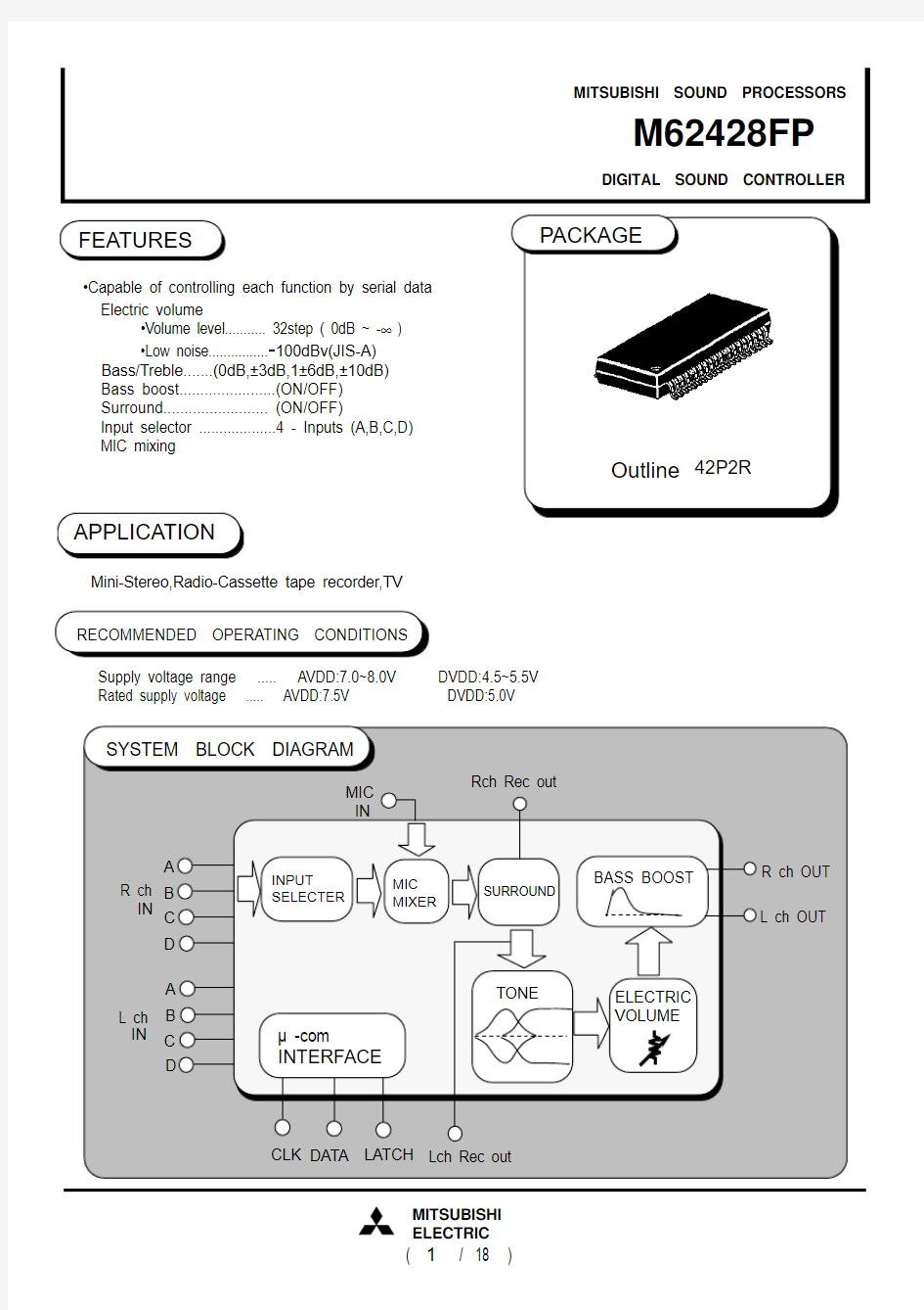
?Volume level........... 32step ( 0dB ~ -∞ ) ?Low noise................-100dBv(JIS-A) Bass/Treble.......(0dB,±3dB,1±6dB,±10dB) Bass boost.......................(ON/OFF) Surround......................... (ON/OFF)
Input selector ...................4 - Inputs (A,B,C,D) MIC mixing
Mini-Stereo,Radio-Cassette tape recorder,TV Supply voltage range ..... AVDD:7.0~8.0V DVDD:4.5~5.5V Rated supply voltage ..... AVDD:7.5V DVDD:5.0V
Outline 42P2R
?Capable of controlling each function by serial data
DIGITAL SOUND CONTROLLER
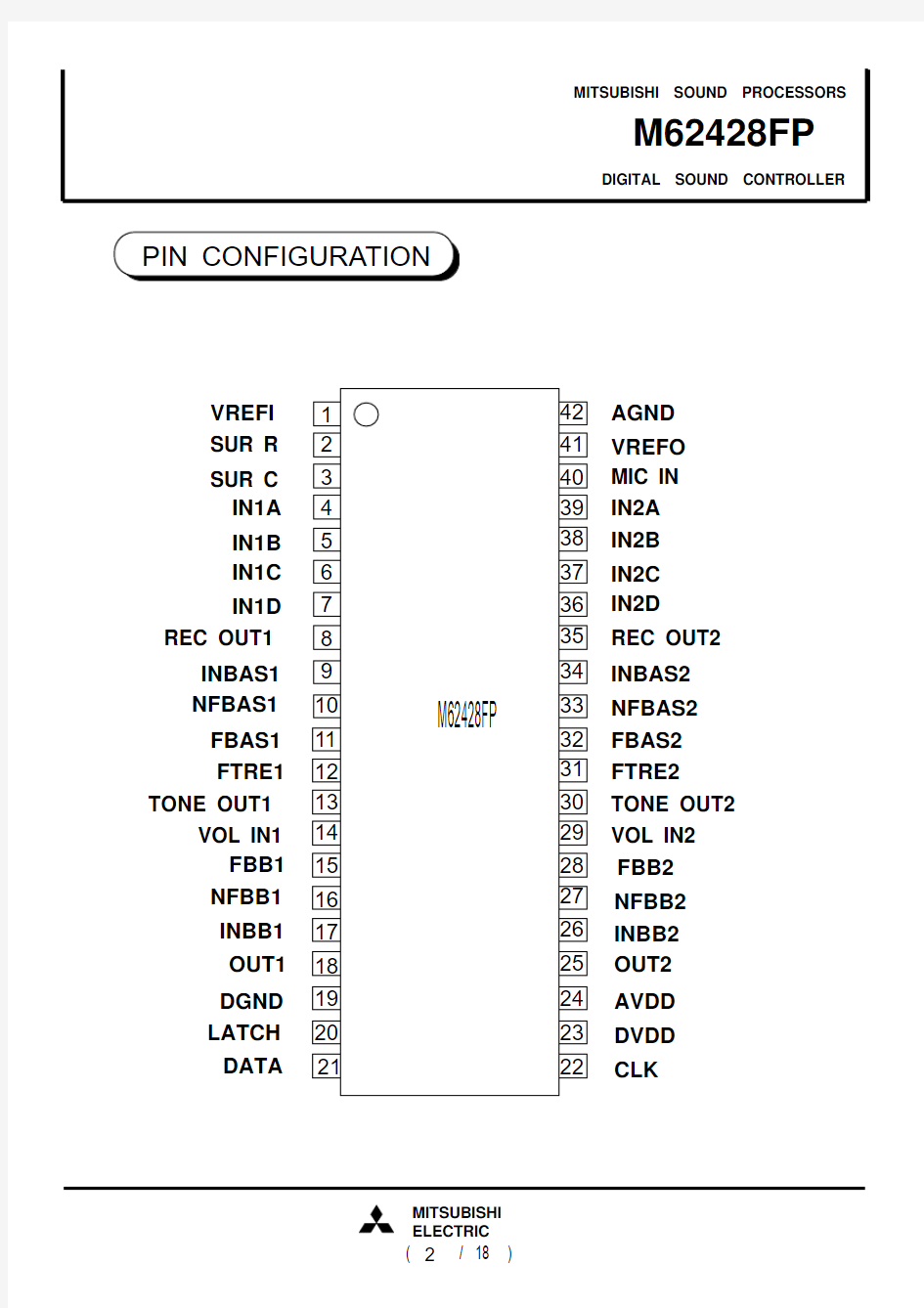
SUR R SUR C DATA
LATCH OUT1IN1A REC OUT1FTRE1
FBAS1NFBAS1INBAS1VOL IN1VREFI IN1B IN1C
IN1D
DGND TONE OUT1
OUT2INBB2NFBB2MIC IN DVDD CLK
VREFO FTRE2
FBAS2NFBAS2REC OUT2INBAS2AGND VOL IN2IN2A IN2B IN2C IN2D AVDD TONE OUT2FBB2INBB1NFBB1
FBB1
DIGITAL SOUND CONTROLLER
OUT2OUT2INBB2NFBB2FBB2MIC IN DVDD CLK VREFO FTRE2FBAS2NFBAS2REC OUT2INBAS2AGND
VOL IN2IN2A IN2B IN2C IN2D AVDD TONE SUR R SUR C DATA LATCH OUT1INBB1NFBB1FBB1IN1A REC OUT1FTRE1FBAS1NFBAS1INBAS1VOL IN1VREFI
IN1B IN1C IN1D DGND OUT1TONE Resistance Capacitance
:?:F
Units
DIGITAL SOUND CONTROLLER
124567811121415316Output of bass boosting resonant buffer amp RECOUT1SUR R VREFI External R connection pin for setting time constant for surround RefAmp input
10NFBAS19INBAS11317181920Ground of the internal logic circuit
SUR C External C connection pin for setting time constant for surround
IN1A IN1B
IN1C IN1D Channel 1 input REC output of channel 1
Input of BASS Amp in bass section Output of BASS Amp in bass section
FBAS1FTRE1
Resonant impedance (band-pass filter) connection pin for bass section Resonant impedance (band-pass filter) connection pin for treble section
VOLIN121
R-rudder volume input of channel 1NFBB1INBB1OUT1DGND LATCH DATA
Input pin of latch signal.
Changes the circuit status at the rising edge of the latch signal Resonant impedance (band-pass filter) connection pin for bass boost section Input pin of control data.
Reads data at the rising edge of clock
Channel 1 output
TONEOUT1TONE output of channel 1FBB1Input of bass boosting resonant buffer amp Pin No.Symbol
Function
DIGITAL SOUND CONTROLLER
22232526272829323335362437RefAmp output
31303438394041Ground of the internal analog circuit
Channel 2 input
REC output of channel 2
Input of BASS Amp in bass section Output of BASS Amp in bass section Resonant impedance (band-pass filter) connection pin for bass section Resonant impedance (band-pass filter) connection pin for treble section 42
R-rudder volume input of channel 2Channel 2 output
TONE output of channel 2
Pin No.Symbol
Function
DVDD CLOCK AVDD FTRE2RECOUT2IN2D IN2B IN2C
IN2A MIC IN VREFO AGND
OUT2VOLIN2TONEOUT2NFBAS2INBAS2FBAS2Clock input pin for serial data transfer Power supply of internal logic circuit Power supply of internal analog circuit Microphone input Output of bass boosting resonant buffer amp NFBB2INBB2Resonant impedance (band-pass filter) connection pin for bass boost section
FBB2Input of bass boosting resonant buffer amp
DIGITAL SOUND CONTROLLER
(Ta=25°C,unless otherwise noted)
THERMAL DERATING (MAXIMUM RATING)
P O W E R D I S S I P A T I O N P d (m W )
1000
800600400
2000
025
5075100125
AMBIENT TEMPERATURE Ta (°C)
630
DIGITAL SOUND CONTROLLER
(Ta=25°C,unless otherwise noted)
DATA
CLOCK
Data signal is read at the rising edge of clock.
Signal is latched at the rising edge of the latch signal.
LATCH
H
L H
L H
L
Note 1:After applying AVdd,Apply supply voltages in the order of DVdd for the IC.
DIGITAL SOUND CONTROLLER
CLOCK
DATA
LATCH
t f
DIGITAL SOUND CONTROLLER
2 types of input formats can be selected by changing the D7 slot setting status.
(Initialize all data of the 2 formats when power is turned on.)
(3) Setting code (master volume)
Input direction
Input format selection slot
(1)
(2)
D01D11000D21Amount of ATT
D3101000100000001001010011100000101001001010110100011010110011111110000001100010100111001001011010101101111011100000110000011-∞
-76.0dB 00110011011001101101111
D41111111111111-60.0dB -64.0dB -68.0dB -72.0dB -56.0dB -52.0dB -48.0dB -44.0dB -42.0dB -40.0dB -38.0dB -36.0dB -0.0dB -2.0dB -4.0dB -6.0dB -8.0dB -10.0dB -12.0dB -14.0dB -16.0dB -18.0dB -20.0dB -22.0dB -24.0dB -26.0dB -28.0dB -30.0dB -32.0dB -34.0dB
DIGITAL SOUND CONTROLLER (4) Setting code (bass?treble cut / boost and bass boost on / off)
(5) Setting code (input selector)
DIGITAL SOUND CONTROLLER
(Ta=25°C,AVdd=7.5V,DVdd=5.0V ,f=1kHz
Tone control & Bass Boost setting :0dB , unless otherwise noted)
(1)Power Supply
(2)Input/Output
DIGITAL SOUND CONTROLLER
Min typ Max 10dB (4) Tone control characteristics
Gbboost Gtcut
Gbcut Gtboost -10713-13-7dB dB dB
10dB
-10dB -10dB
(5) Bass boost characteristics
10dB
f=150Hz
f=10kHz
10-10
713-13
-7
(6) Volume characteristics
Limits
Symbol
Parameter
Conditions
Unit
Tone control
voltage gain(bass)
Tone control
voltage gain(treble)
(input to pin 4 and 39),(input to pin 5 and 38),(input to pin 6 and 37),(input to pin 7 and 36),output from pin 13 and 30
(3) MIC AMP characteristics
DIGITAL SOUND CONTROLLER
Resistance Capacitance :?:F
Units
DIGITAL SOUND CONTROLLER
(1) Tone controller equivalent circuit
C1
C2
Fig.2 An equivalent circuit using L
C1
L
R3
EXAMPLE : BASS BAND ( f=150Hz ) R1=1.5K ? , R2=56K ? C1=0.82μ, C2=0.015μ
CENTER FREQUENCY
f0 = 1 / 2 π C1?C2?R1?R2 [Hz]Q = (C2?R2 )/ (C1?R1)
Fig.1 A circuit equivalent to the inside of the tone controller
Fig.2 is equivalent to Fig.1. To convert
component constants, the equation below is used.
L=C2 ?R1?R2
DIGITAL SOUND CONTROLLER
BAND-PASS FILTER
REGULATING SURROUND
MIC INPUT
(2) Surround block equivalent circuit
CHANNEL1 OUTPUT
CHANNEL2 OUTPUT
DIGITAL SOUND CONTROLLER
DIGITAL SOUND CONTROLLER
O U T 1
Resistance Capacitance :?:F
Units