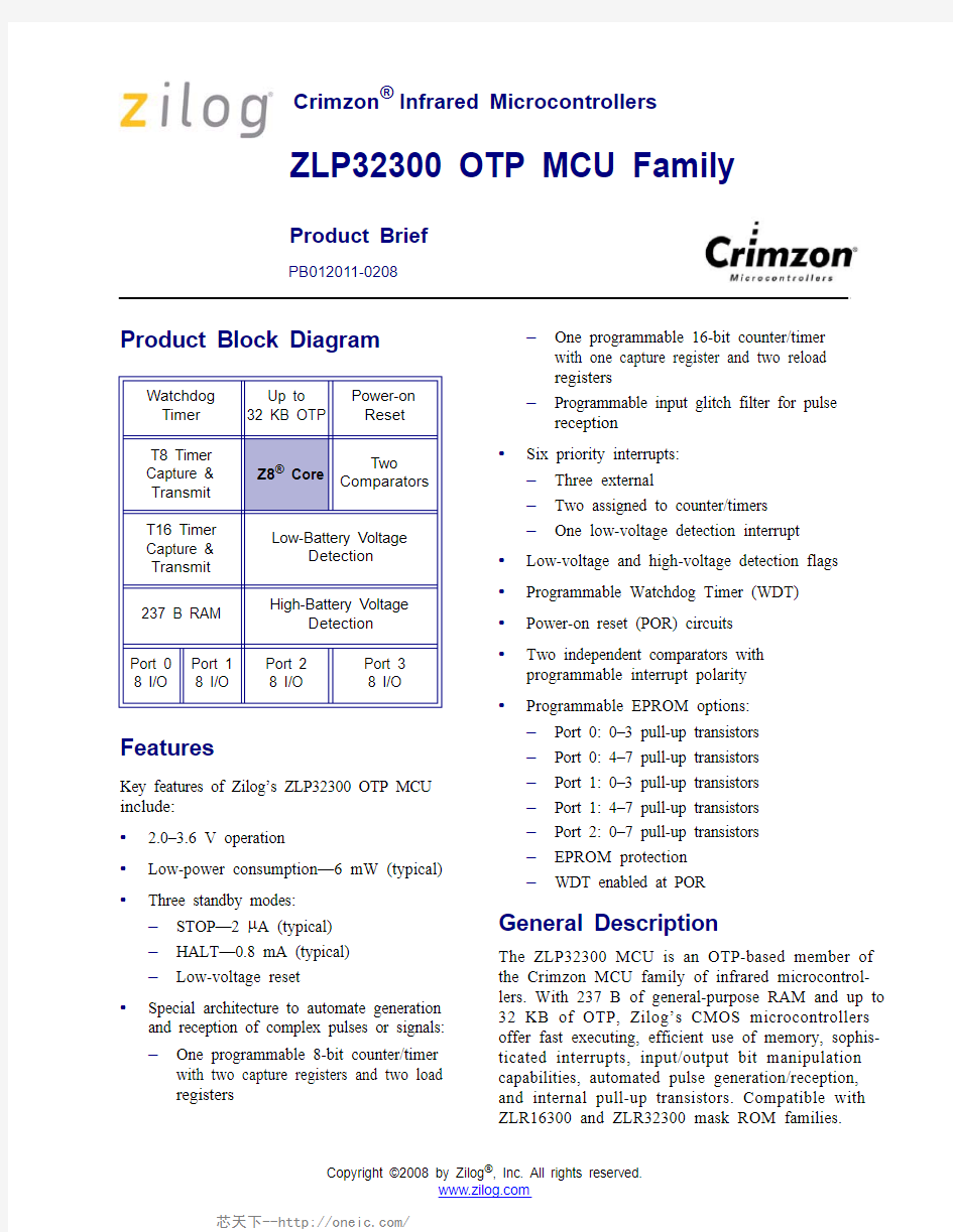
Product Block Diagram
Features
Key features of Zilog’s ZLP32300 OTP MCU include:
? 2.0–3.6 V operation
?Low-power consumption—6 mW (typical)?Three standby modes:
–STOP—2 μA (typical)
–HALT—0.8 mA (typical)
–Low-voltage reset
?Special architecture to automate generation and reception of complex pulses or signals:
–One programmable 8-bit counter/timer with two capture registers and two load
registers
–One programmable 16-bit counter/timer with one capture register and two reload
registers
–Programmable input glitch filter for pulse reception
?Six priority interrupts:
–Three external
–Two assigned to counter/timers
–One low-voltage detection interrupt ?Low-voltage and high-voltage detection flags ?Programmable Watchdog Timer (WDT)?Power-on reset (POR) circuits
?Two independent comparators with
programmable interrupt polarity ?Programmable EPROM options:
–Port 0: 0–3 pull-up transistors
–Port 0: 4–7 pull-up transistors
–Port 1: 0–3 pull-up transistors
–Port 1: 4–7 pull-up transistors
–Port 2: 0–7 pull-up transistors
–EPROM protection
–WDT enabled at POR
General Description
The ZLP32300 MCU is an OTP-based member of the Crimzon MCU family of infrared microcontrol-lers. With 237 B of general-purpose RAM and up to 32 KB of OTP, Zilog’s CMOS microcontrollers offer fast executing, efficient use of memory, sophis-ticated interrupts, input/output bit manipulation capabilities, automated pulse generation/reception, and internal pull-up transistors. Compatible with ZLR16300 and ZLR32300 mask ROM families.
Watchdog Timer
Up to
32 KB OTP
Power-on
Reset
T8 Timer Capture & Transmit
Z8? Core
Two
Comparators
T16 Timer Capture & Transmit Low-Battery Voltage
Detection
237 B RAM High-Battery Voltage
Detection
Port 0 8 I/O Port 1
8 I/O
Port 2
8 I/O
Port 3
8 I/O
Crimzon?Infrared Microcontrollers
PB012011-0208
ZLP32300 OTP MCU Family
Product Brief
Copyright ?2008 by Zilog?, Inc. All rights reserved.
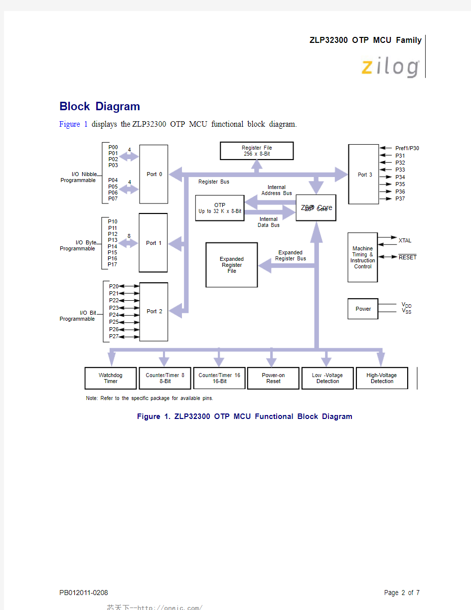
Block Diagram
Figure 1 displays the ZLP32300 OTP MCU functional block diagram.
Figure 1. ZLP32300 OTP MCU Functional Block Diagram
Z8? Core Port 2
Port 0
P21P22P23P24P25P26P27
P20I/O Bit
Programmable
P04P05P06P07
P00P01P02P03
I/O Nibble Programmable
Register File 256 x 8-Bit
Register Bus
Internal Address Bus
Internal Data Bus
Expanded Register File
Expanded Register Bus
Z8? Core
Counter/Timer 8
8-Bit Counter/Timer 16
16-Bit V DD V SS
XTAL
RESET
Pref1/P30P31P32P33P34P35P36P37
Port 3
Machine Timing &Instruction Control
Power
4
4
OTP
Up to 32 K x 8-Bit
Port 1
P14P15P16P17
P10P11P12P13I/O Byte
Programmable
8
Watchdog Timer Low -Voltage Detection High-Voltage Detection
Power-on Reset Note: Refer to the specific package for available pins.
Pin-Outs
Figure 2 displays the pins for the 20-pin ZLP32300 OTP MCU.
Figure 2. 20-Pin DIP/SOIC/SSOP Pin Assignment
Figure 3 displays the pins for the 28-pin ZLP32300 OTP MCU.
Figure 3. 28-Pin DIP/SOIC/SSOP Pin Assignment
P25P26P27P07V DD XTAL2XTAL1P31P32P33P24P23P22P21P20V SS P01
P00/Pref1/P30P36P34
12345678910
2019181716151413121120-Pin PDIP SOIC SSOP
P24P23P22P21P20P03V SS P02P01P00
Pref1/P30P36P37P35
P25P26P27P04P05P06P07V DD XTAL2XTAL1P31P32P33P34128-Pin PDIP SOIC SSOP
234567891011121314
2827262524232221201918171615
Figure 4 displays the 40-pin version of the ZLP32300 OTP MCU.
Figure 4. 40-Pin PDIP Pin Assignment
NC P25P26P27P04P05P06P14P15P07VDD P16P17XTAL2XTAL1P31P32P33P34NC NC P24P23P22P21P20P03P13P12VSS P02P11P10P01P00
Pref1/P30P36P37P35RESET
40-Pin PDIP
1234567891011121314151617181920
4039383736353433323130292827262524232221
Figure 5 displays the 48-pin version of the ZLP32300 OTP MCU.
Figure 5. 48-Pin SSOP Assignment
NC P25P26P27P04N/C P05P06P14P15P07VDD VDD N/C P16P17XTAL2XTAL1P31P32P33P34NC VSS
NC NC P24P23P22P21P20P03P13P12VSS VSS N/C P02P11P10P01P00N/C
PREF1/P30P36P37P35RESET
48-Pin SSOP
123456789101112131415161718192021222324
484746454443424140393837363534333231302928272625
Ordering Information
You can order ZLP32300 OTP MCU products from Zilog ?, using the part numbers provided in the table below . For more information on ordering, please consult your local Zilog sales office. The Zilog website (https://www.doczj.com/doc/eb6109611.html, ) lists all regional offices, as well as additional ZLP32300 OTP MCU Series product information.
Development Tools
Part Number Description
Part Number Description
ZLP32300H483248-pin SSOP 32 K OTP ZLP32300H480848-pin SSOP 8 K OTP ZLP32300P403240-pin PDIP 32 K OTP ZLP32300P400840-pin PDIP 8 K OTP ZLP32300H283228-pin SSOP 32 K OTP ZLP32300H280828-pin SSOP 8 K OTP ZLP32300P283228-pin PDIP 32 K OTP ZLP32300P280828-pin PDIP 8 K OTP ZLP32300S283228-pin SOIC 32 K OTP ZLP32300S280828-pin SOIC 8 K OTP ZLP32300H203220-pin SSOP 32 K OTP ZLP32300H200820-pin SSOP 8 K OTP ZLP32300P203220-pin PDIP 32 K OTP ZLP32300P200820-pin PDIP 8 K OTP ZLP32300S203220-pin SOIC 32 K OTP ZLP32300S2008
20-pin SOIC 8 K OTP
ZLP32300H481648-pin SSOP 16 K OTP ZLP323ICE01ZAC*40-PDIP/48-SSOP
Accessory Kit
ZLP32300P401640-pin PDIP 16 K OTP ZLP32300H281628-pin SSOP 16 K OTP Note: *This kit has been replaced by an improved version, ZCRMZNICE02ZACG.
ZLP32300P281628-pin PDIP 16 K OTP ZLP32300S281628-pin SOIC 16 K OTP ZLP32300H201620-pin SSOP 16 K OTP ZLP32300P201620-pin PDIP 16 K OTP ZLP32300S2016
20-pin SOIC 16 K OTP
Development Kit Part Numbers ZLP128ICE01ZEMG*In-Circuit Emulator
Note: *This kit has been replaced by an improved version, ZCRMZNICE01ZEMG.
ZCRMZNICE01ZEMG Crimzon In-Circuit Emulator ZCRMZNICE01ZACG 20-Pin Accessory Kit ZCRMZNICE02ZACG 40/48-Pin Accessory Kit ZCRMZN00100KITG
Crimzon IR Development Kit
DO NOT USE IN LIFE SUPPORT
LIFE SUPPORT POLICY
ZILOG'S PRODUCTS ARE NOT AUTHORIZED FOR USE AS CRITICAL COMPONENTS IN LIFE SUPPORT DEVICES OR SYSTEMS WITHOUT THE EXPRESS PRIOR WRITTEN APPROV AL OF THE PRESIDENT AND GENERAL COUNSEL OF ZILOG CORPORATION.
As used herein
Life support devices or systems are devices which (a) are intended for surgical implant into the body, or (b) support or sustain life and whose failure to perform when properly used in accordance with instructions for use provided in the labeling can be reasonably expected to result in a significant injury to the user. A critical component is any component in a life support device or system whose failure to perform can be reasonably expected to cause the failure of the life support device or system or to affect its safety or effectiveness.
Document Disclaimer
?2008 by Zilog, Inc. All rights reserved. Information in this publication concerning the devices, applications, or technology described is intended to suggest possible uses and may be superseded. ZILOG , INC. DOES NOT ASSUME LIABILITY FOR OR PROVIDE A REPRESENTATION OF ACCURACY OF THE INFORMATION, DEVICES, OR TECHNOLOGY DESCRIBED IN THIS DOCUMENT. ZILOG ALSO DOES NOT ASSUME LIABILITY FOR INTELLECTUAL PROPERTY INFRINGEMENT RELATED IN ANY MANNER TO USE OF INFORMATION, DEVICES, OR TECHNOLOGY DESCRIBED HEREIN OR OTHERWISE. The information contained within this document has been verified according to the general principles of electrical and mechanical engineering. Z8 and Crimzon are trademarks or registered trademarks of Zilog, Inc. All other product or service names are the property of their respective owners.
Warning: