a r X i v :0803.4420v 2 [h e p -p h ] 31 M a y 2008
Magnetic Moments of Heavy ΞQ Baryons in
Light Cone QCD Sum Rules
T.M.Aliev ?,K.Azizi ?,A.Ozpineci
?
Physics Department,Middle East Technical University,06531,Ankara,Turkey
Abstract
The magnetic moments of heavy ΞQ baryons containing a single
charm or bottom quark are calculated in the framework of light cone QCD sum rules method.A comparison of our results with the predic-tions of other approches,such as relativistic and nonrelativistic quark models,hyper central model,Chiral perturbation theory,soliton and skyrmion models is presented.
PACS:11.55.Hx,13.40.Em,14.20.Lq,14.20.Mr
1Introduction
During the last few years,exciting experimental results are obtained in the baryon sector containing a single b-quark.The CDF Collaboration observed
the statesΣ±
b andΣ?±
b
[1],while both DO[2]and CDF[3]Collaborations
have seenΞb.Recently,BaBar Collaboration reported the discovery of??c with mass splitting m??
c?m?c=(70.8±1.0±1.1)MeV[4].
The masses of the heavy baryons have been studied in the framework of various phenomenological models[5]-[13]and also in the framework of QCD sum rules method[14]-[26].Along with their masses,another static parameter of the heavy baryons is their magnetic moment.Study of the mag-netic moments can give valuable information about the internal structures of hadrons.
The magnetic moments of heavy baryons have been studied in the frame-work of di?erent methods.In[27,28]the magnetic moments of charmed baryons are calculated within naive quark model.In[29,30],magnetic mo-ments of charmed and bottom baryons are analyzed in quark model and in [31]heavy baryon magnetic moments are studied in bound state approach. Magnetic moments of heavy baryons are calculated in the relativistic three-quark model[32],hyper central model[33],Chiral perturbation model[34], soliton model[35],skyrmion model[36]and nonrelativistic constituent quark model with light and strangeˉq q pairs[37].In[38]the magnetic moments ofΣc andΛc baryons are calculated in QCD sum rules in external electro-magnetic?eld.In[39,40],the light cone QCD sum rules method is applied to study the magnetic moments of theΛQ,(Q=c,b)andΣQΛQ transitions (more about this method can be found in[41,42,43,44]and references therein).
The aim of the present work is the calculation of the magnetic moments
1
of theΞb baryons recently observed by DO and CDF Collaborations within the light cone QCD sum rules framework.The plan of the paper is as follows. In section2,using the general form of the the baryon current,the light cone QCD sum rules forΞb andΞc baryons are calculated.In section3we present our numerical calculations on theΞb andΞc baryons.In this section we also present a comparison of our results with the predictions of other approaches.
2Light cone QCD sum rules for theΞQ mag-netic moments
In order to calculate the magnetic moments ofΞQ(Q=b,c)in the framework of the light cone QCD sum rules,we need the expression for the interpolating current ofΞQ.To construct it,we follow[11],i.e.we assume that the strange and light quarks(sq)inΞQ are in a relative spin zero state(scalar or pseudo scalar diquarks).Therefore,the most general current without derivatives and with the quantum numbers ofΞQ can be constructed from the combination of aforementioned scalar or pseudoscalar diquarks in the following way
ηQ=εabc[(q aT Cs b)γ5+β(q aT Cγ5s b)]Q c,(1)
here a,b and c are color indices,C is the charge conjugation operator,Q=b, or c,q=u,or d andβis an arbitrary parameter.Having the explicit ex-pression for the interpolating current,our next task is to construct light cone QCD sum rules for the magnetic moments ofΞQ baryons.It is constructed from the following correlation function:
Π(p,q)=i d4xe ipx<γ|T{ηQ(x)ˉηQ(0)|}0>.(2) The calculation of the phenomenological side at the hadronic level pro-ceeds by inserting into the correlation function a complete set of hadronic
2
states with the quantum numbers ofΞQ.We get
Π= i<0|ηQ|ΞQ i(p2)>p21?m2ΞQ.(3) Isolating the ground state’s contributions,Eq.(3)can be written as
Π=<0|ηQ|ΞQ(p2)>
p21?m2ΞQ
+ h i<0|ηQi|h i(p2)>p21?m2h i,(4) where p1=p+q,p2=p and q is the photon momentum.The second term in Eq.(4)describes the higher resonances and continuum contributions.The coupling of the interpolating current with the baryonsΞQ is determined as
<0|ηQ|ΞQ(p)>=λQ uΞQ(p),(5) where uΞ
Q
(p)is a spinor describing the baryonΞQ with four momentum p andλQ is the corresponding residue.
The last step for obtaining the expression for the physical part of the correlator function is to write down the matrix element<ΞQ(p2)|ΞQ(p1)>γin terms of the form https://www.doczj.com/doc/db7207139.html,ing Lorentz covariance,this matrix element can be written as
<ΞQ(p1)|ΞQ(p2)>γ=εμ
2mΞ
Q
f2 uΞQ(p2)
=
2mΞ
Q
f2 uΞQ(p2)εμ,(6)
where f1(q2)and f2(q2)are the form factors andεμis the photon polarization vector.
3
For calculation of theΞQ magnetic moments,the values of the form factors only at q2=0are needed because the photon is real in our https://www.doczj.com/doc/db7207139.html,ing Eqs.(4-6)for physical part of the correlator and summing over the spins of initial and?nalΞQ baryons,the correlation function becomes
Π=?λ2Qεμp2+mΞQ
2mΞ
Q
f2 p1+mΞQ p21?m2ΞQμΞQ
1
where S ′i =CS T i C and C and T are the charge conjugation and transposition operators,respectively and S Q and S q (s )are the heavy and light(strange)quark propagators.
The correlation function from QCD part receives three di?erent contribu-tions:a)perturbative contributions,b)nonperturbative contributions,where photon is emitted from the freely propagating quark (in other words at short distance)c)nonperturbative contributions,when photon is radiated at long distances.To obtain the expression for the contribution from the emission of photon at short distances,the following procedure can be used:Each one of the quarks can emit the photon,and hence each term in Eq.(9)corre-sponds to three terms in which the propagator of the photon emitting quark is replaced by:
S ab
αβ
??1
2π2x 4
?
m q
4π2
K 1(m Q
√
√
4π2x 2
K 2(m Q
√
4
ˉq a Γj q b (Γj )αβ,
(12)
5
where Γj =
1,γ5,γα,iγ5γα,σαβ/
√
(2π)
4
e ?ikx
1
dv
k +m Q
m 2Q ?k
2vx μG μν
γν ,S q (x )=
S free
q (x )
?
m q
12
1?i
m q
192
m 20 ˉq
q 1?i
m q
16π2x 2
G μν(ux )σμν?ux μ
G μν(ux )γ
ν
i
32π
2G μν
σμν
ln ?x 2Λ2
distribution amplitudes[46].
γ(q)|ˉq(x)σμνq(0)|0 =?ie qˉq q(εμqν?ενqμ) 10due iˉu qx χ?γ(u)+x2
e q ˉq q xν εμ?qμεx qx 10due iˉu qx hγ(u)
2(qx)
γ(q)|ˉq(x)γμq(0)|0 =e q f3γ εμ?qμεx
e q f3γ?μναβενqαxβ 10due iˉu qxψa(u)
4
γ(q)|ˉq(x)g s Gμν(vx)q(0)|0 =?ie q ˉq q (εμqν?ενqμ) Dαi e i(αˉq+vαg)qx S(αi)
γ(q)|ˉq(x)g s?Gμνiγ5(vx)q(0)|0 =?ie q ˉq q (εμqν?ενqμ) Dαi e i(αˉq+vαg)qx?S(αi) γ(q)|ˉq(x)g s?Gμν(vx)γαγ5q(0)|0 =e q f3γqα(εμqν?ενqμ) Dαi e i(αˉq+vαg)qx A(αi) γ(q)|ˉq(x)g s Gμν(vx)iγαq(0)|0 =e q f3γqα(εμqν?ενqμ) Dαi e i(αˉq+vαg)qx V(αi) γ(q)|ˉq(x)σαβg s Gμν(vx)q(0)|0 =e q ˉq q εμ?qμεx qx(qαxν+qνxα) qβ? εμ?qμεx qx(qβxν+qνxβ) qα
? εν?qνεx qx(qαxμ+qμxα) qβ
+ εν?qνεx qx(qβxμ+qμxβ) qα Dαi e i(αˉq+vαg)qx T1(αi)
+ εα?qαεx qx(qμxβ+qβxμ) qν
? εα?qαεx qx(qνxβ+qβxν) qμ
? εβ?qβεx qx(qμxα+qαxμ) qν
+ εβ?qβεx qx(qνxα+qαxν) qμ Dαi e i(αˉq+vαg)qx T2(αi)
7
1
+
(qαxβ?qβxα)(εμqν?ενqμ) Dαi e i(αˉq+vαg)qx T4(αi) (14) qx
whereχis the magnetic susceptibility of the quarks,?γ(u)is the leading twist
2,ψv(u),ψa(u),A and V are the twist3and hγ(u),A,T i(i=1,2,3,4)are
the twist4photon distribution amplitudes(DA’s),respectively.The explicit
expressions of DA’s are presented in numerical analysis section.
The theoretical part of the correlation function can be obtained in terms
of QCD parameters by substituting photon DA’s and expressions for heavy
and light quarks propagators in to Eq.(9).Sum rules for theΞQ magnetic
moments are obtained by equating two representations of the correlation
function.The higher states and continuum contributions are modeled using
the hadron-quark duality.Applying double Borel transformations on the
variables p21=(p+q)2and p22=p2on both sides of the correlator,for the
ΞQ baryon magnetic moments we get:
?λ2Q(β)μΞQ e?m2ΞQ/M2B= s0m2Q e?s
M2B
M2B m2Q
M2B m2Q
M2B
?3e q (β2+1)f 3γm s <ˉs s >η2
?
(β2?1)e ?m 2Q
96π2m 2Q
(6e Q +e s )γE m 20<ˉq
q >
?
e ?m 2Q
288π2
3(β2
?
1)e Q m 20
<ˉq q >
?3+2γE +2ln [
Λ2
m 2Q
])
+
9e Q m 2Q m s
M 21+M 22
and u 0=
M 21
144π2M 2
B
m 2
0(6e Q +e s )m s <ˉq q >ln(?m Q 2+s 64π4
13
6ψ20
?12
]ln (
s
6ψ41
+(1?β2)m s <ˉq q >ψ10
Λ2
)
?
m s
Λ2
)?(4γE +ln [
Λ2
+m2Q
m4
Q
m20m s<ˉq q> ?(1+γE)(ψ22+2ψ12)
?ψ02?ψ32?ψ22?γEΛ2)?ln(Λ2
m2
Q
(β2?1)m s<ˉq q>η1ψ21
+(1+β2)f3γη2 ψ21?ψ10+12ψ00+ln(m2Q
s m(m2
Q )n?m
,
(18)
Note that the contributions of the terms~
λ2Q(β)=e mΞQ2/M2B s0m2Q ds e?s/M2B (1+β2)m4Q x2?8 24π2
(1?x2) (1?β2) ˉq q +(1+b2)?
2103π4
(1?x)(1+5x)
10
+m s
6
e?m2Q/M2B?(1?β2)m20<ˉq q> e?m2Q/M2B
+ 10dα(1?α)e?m2Q6(1?β2)e?m2Q/M2B ,(19) where,x=m2Q/s.
3Numerical analysis
The present section is devoted to the numerical analysis of the magnetic moments ofΞQ baryons.The values of the input parameters,appearing
in the sum rules expression for magnetic moments are: ˉu u (1GeV)=
ˉdd (1GeV)=?(0.243)3GeV3,?(1GeV)=0.8 ˉu u (1GeV),m20(1GeV)=
0.8GeV2[47],,Λ=300MeV and f3γ=?0.0039GeV2[46].The value
of the magnetic susceptibilityχ(1GeV)=?3.15±0.3GeV?2was obtained
by a combination of the local duality approach and QCD sum rules[46]. Recently,from the analysis of radiative heavy meson decay,χ(1GeV)=
?(2.85±0.5)GeV?2was obtained[48],which is in good agreement with
the instanton liquid model prediction[49],but slightly below the QCD sum
rules prediction[46].Note that?rstly the magnetic susceptibility in the framework of QCD sum rules is calculated in[50]and it is obtained that
χ(1GeV)=?4.4GeV?2.In the numerical analysis,we have used all three
value ofχexisting in the litrature and obtained that the values of the mag-
netic moments ofΞQ baryons are practically insensitive to the value ofχ.
The photon DA’s entering the sum rules for the magnetic moments ofΞQ
are calculated in[46]and their expressions are:
?γ(u)=6uˉu 1+?2(μ)C3
ψv(u)=3 3(2u?1)2?1 +3
2 1+916w Aγ ,
A(αi)=360αqαˉqα2g 1+w Aγ1
2
2
(u?ˉu),
A(u)=40u2ˉu2 3κ?κ++1
+8(ζ+2?3ζ2)[uˉu(2+13uˉu)
+2u3(10?15u+6u2)ln(u)+2ˉu3(10?15ˉu+6ˉu2)ln(ˉu) ,
T1(αi)=?120(3ζ2+ζ+2)(αˉq?αq)αˉqαqαg,
T2(αi)=30α2g(αˉq?αq) (κ?κ+)+(ζ1?ζ+1)(1?2αg)+ζ2(3?4αg) ,
T3(αi)=?120(3ζ2?ζ+2)(αˉq?αq)αˉqαqαg,
T4(αi)=30α2g(αˉq?αq) (κ+κ+)+(ζ1+ζ+1)(1?2αg)+ζ2(3?4αg) ,
S(αi)=30α2g{(κ+κ+)(1?αg)+(ζ1+ζ+1)(1?αg)(1?2αg)
+ζ2[3(αˉq?αq)2?αg(1?αg)]},
?S(αi)=?30α2g{(κ?κ+)(1?αg)+(ζ1?ζ+1)(1?αg)(1?2αg)
+ζ2[3(αˉq?αq)2?αg(1?αg)]}.(20) The constants appearing in the wave functions are given as[46]?2(1GeV)=
0,w Vγ=3.8±1.8,w Aγ=?2.1±1.0,κ=0.2,κ+=0,ζ1=0.4,ζ2=0.3,
ζ+1=0andζ+2=0.
From the explicit expressions of the magnetic moments ofΞQ baryons,it follows that it contains three auxiliary parameters:Borel mass squared M2B, continuum threshold s0andβwhich enters the expression of the interpolating
current forΞQ.The physical quantity,magnetic momentμΞ
Q
,should be independent of these auxiliary parameters.In other words we should?nd
12
the”working regions”of these auxiliary parameters,where the magnetic
moments are independent of them.
The value of the continuum threshold is?xed from the analysis of the two-point sum rules,where the mass and residueλΞ
Q
of theΞQ baryons are determined[25],which leads to the value s0=6.52GeV2forΞb and s0=3.02GeV2forΞc.If we choose the value s0=6.42GeV2forΞb and s0=8GeV2forΞc.the results remain practically unchanged.Next,we
try to?nd the working region of M2B whereμΞ
Q
are independent of it at ?xed value ofβand the above mentioned values of s0.The upper bound of M2B is obtained requiring that the continuum contribution should be less than the contribution of the?rst resonance.The lower bound of M2B is determined by requiring that the highest power of1/M2B be less than300/0 of the highest power of M2B.These two conditions are both satis?ed in the region15GeV2≤M2B≤20GeV2and5GeV2≤M2B≤8GeV2forΞb and Ξc,respectively.
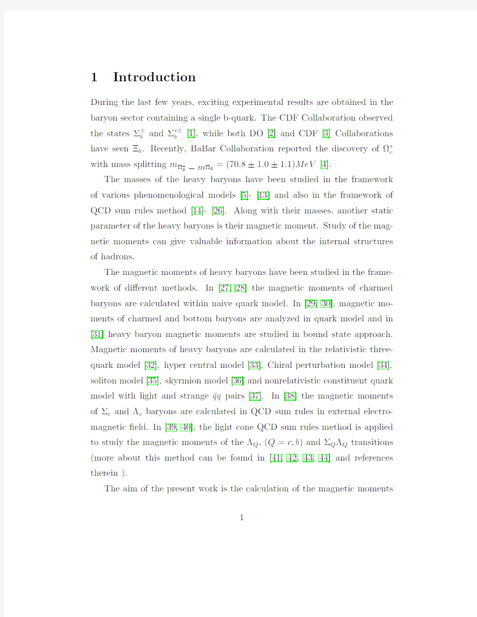
In Figs.1and2,we depict the dependence ofμΞ0
b andμ
Ξ?
b
on M2B at?xed
value ofβand s0=6.52GeV2.In Figs.3and4,we present the dependence
ofμΞ0
c andμ
Ξ+c
on M2B at?xed value ofβand s0=3.02GeV2.From these
?gures,we see that the values of the magnetic moments ofΞb andΞc exhibit good stability when M2B varies in the region15GeV2≤M2B≤20GeV2
and5GeV2≤M2B≤8GeV2,respectively.The last step of our analysis is the determination of the working region for the auxiliary parameterβ.For this aim,in Figs.5,6,7,and8we present the dependence of the magnetic moments ofΞQ baryons on cosθwhere tanθ=β,using the values of M2B from the”working region”which we already determined and at?xed values of s0.
From these?gures we obtained that the prediction of the magnetic mo-
13
mentμΞ
b (μΞ
c
)is practically independent of the value of the auxiliary param-
eterβ.From all these analysis we deduce the?nal results for the magnetic moments in Table1forχ=?https://www.doczj.com/doc/db7207139.html,parison of our results on the magnetic moments ofΞQ baryons with predictions of other approaches,as we already noted,is also presented in Table1.
μΞ?
b μΞ+c
?0.045±0.0050.35±0.05
RQM[32]-0.060.41
-0.060.37
[33]-0.45÷0.48
-0.32
[35]-0.38
-0.28
[37]-0.39÷0.46
Table1:Results for the magnetic moments ofΞQ baryons in di?erent ap-proaches.
We see that within errors our predictions on the magnetic moments are in good agreement with the quark model predictions.Our results on the mag-netic moments ofΞc are also close to the predictions of the other approaches
except the prediction of[33]onμΞ0
c
.
In summary,the magnetic moments ofΞQ baryons,which were discovered recently(more preciselyΞb was discovered)are calculated in framework of light cone QCD sum rules.Our results on magnetic moments are close to the predictions of the other approaches existing in the literature.
14
4Acknowledgment
Two of the authors(K.A.and A.O.),would like to thank TUBITAK, Turkish Scienti?c and Research Council,for their partial?nancial support both through the scholarship program and also through the project number 106T333.One of the authors(A.O.)would like to thank TUBA for funds provided through the GEBIP program.
References
[1]T.Aaltonen et.al,CDF Collaboration,Phys.Rev.Lett.99(2007)
202001.
[2]V.Abazov et.al,DO Collaboration,Phys.Rev.Lett.99(2007)052001.
[3]T.Aaltonen et.al,CDF Collaboration,Phys.Rev.Lett.99(2007)
052002.
[4]B.Aubert et.al,BaBar Collaboration,Phys.Rev.Lett.97(2006)
232001.
[5]S.Capstick,N.Isgur,Phys.Rev.D34(1986)2809.
[6]R.Roncaglia,D.B.Lichtenberg,E.Predazzi,Phys.Rev.D52(1995)
1722.
[7]E.Jenkins,Phys.Rev.D54(1996)4515.
[8]N.Mathur,R.Lewis,R.M.Woloshyn,Phys.Rev.D66(2002)014502.
[9]D.Ebert,R.N.Faustov,V.O.Galkin,Phys.Rev.D72(2005)034026.
[10]M.Karliner,H.J.Lipkin,arXiv:0307343(hep-ph),0611306(hep-ph).
15
[11]M.Karliner,B.Kereu-Zura,H.J.Lipkin,J.L.Rosner,arXiv:0706.2163
(hep-ph).
[12]J.L.Rosner,Phys.Rev.D75(2007)013009.
[13]M.Karliner,H.J.Lipkin,Phys.Lett.B575(2003)249.
[14]M.A.Shifman,A.I.Vainshtein,V.I.Zakharov,Nucl.Phys.B147
(1979)385.
[15]E.Bagan,M.Chabab,H.G.Dosch,S.Narison,Phys.Lett.B278
(1992)367;ibid;Phys.Lett.B287(1992)176;ibid;Phys.Lett.B301 (1993)243.
[16]C.S.Navarra,M.Nielsen,Phys.Lett.B443(1998)285.
[17]E.V.Shuryak,Nucl.Phys.B198(1982)83.
[18]A.G.Grozin,O.I.Yakovlev,Phys.Lett.B285(1992)254.
[19]Y.B.Dai,C.S.Huang,C.Liu,C.D.Lu,Phys.Lett.B371(1996)99.
[20]D.W.Wang,M.Q.Huang,C.Z.Li,Phys.Rev.D65(2002)094036.
[21]S.L.Zhu,Phys.Rev.D61(2000)114019.
[22]C.S.Huang,A.L.Zhang,S.L.Zhu,Phys.Lett.B492(2000)288.
[23]D.W.Wang,M.Q.Huang,Phys.Rev.D68(2003)034019.
[24]Z.G.Wang,Eur.Phys.J.C54(2008)231.
[25]F.O.Duraes,M.Nielsen,Phys.Lett.B658(2007)40.
[26]X.Liu,H.X.Chen,Y.R.Liu,A.Hosaka,S.L.Zhu,Phys.Rev.D77
(2008)014031.
16
[27]A.L.Choudhury,V.Joshi,Phys.Rev.D13(1976)3115.
[28]D.B.Lichtenberg,Phys.Rev.D15(1977)345.
[29]L.Y.Glozman,D.O.Riska,Nucl.Phys.A603(1996)326.
[30]B.Julia-Diaz,D.O.Riska,Nucl.Phys.A739(2004)69.
[31]S.Scholl,H.Weigel,Nucl.Phys.A735(2004)163.
[32]A.Faessler et.al,Phys.Rev.D73(2006)094013.
[33]B.Patel,A.K.Rai,P.C.Vinodkumar,arXiv:0803.0221(hep-ph).
[34]M.Savage,Phys.Lett.B326(1994)303.
[35]D.O.Riska,Nucl.Instrum.Meth.B119(1996)259.
[36]Y.Oh,D.P.Min,M.Rho,N.N.Scoccola,Nucl.Phys.A534(1991)
493.
[37]C.S.An,Nucl.Phys.A797(2007)131,Erratum-ibid;A801(2008)
82.
[38]S.L.Zhu,W.Y.Hwang,Z.S.Yang,Phys.Rev.D56(1997)7273.
[39]T.M.Aliev,A.Ozpineci,M.Savci,Phys.Rev.D65(2002)096004.
[40]T.M.Aliev,A.Ozpineci,M.Savci,Phys.Rev.D65(2002)056008.
[41]P.Colangelo and A.Khodjamirian,in”At the Frontier of Particle
Physics/Handbook of QCD”,edited by M.Shifman(World Scienti?c, Singapore,2001),Vol.3,p.1495.
[42]V.M.Braun,Prep.arXiv:9801222(hep-ph).
17
[43]I.I.Balitsky,V.M.Braun,Nucl.Phys.B311(1989)541.
[44]V.M.Braun,I.E.Filyanov,Z.Phys.C48(1990)239.
[45]T.M.Aliev,A.Ozpineci,M.Savci,Phys.Rev.D66(2002)016002,
Erratum-ibid;D67(2003)039901.
[46]P.Ball,V.M.Braun,N.Kivel,Nucl.Phys.B649(2003)263.
[47]V.M.Belyaev,B.L.Io?e,JETP56(1982)493.
[48]J.Rohrwild,JHEP0709(2007)073.
[49]A.E.Dorokhov,Eur.J.Phys.C42(2005)309.
[50]V.M.Belyaev,I.I.Kogan,Yad.Fiz.40(1984)1035.
18
Figure1:The dependence of magnetic momentμΞ0
b on M2B at s0=6.52GeV2
andβ=±5,?1.
19
电源磁芯尺寸功率参数
常用电源磁芯参数 MnZn 功率铁氧体 EPC 功率磁芯 特点:具有热阻小、衰耗小、功率大、工作频率宽、重量 轻、结构合理、易表面贴装、屏蔽效果好等优点,但散热 性能稍差。 用途:广泛应用于体积小而功率大且有屏蔽和电磁兼容要 求的变压器,如精密仪器、程控交换机模块电源、导航设 备等。 EPC型功率磁芯尺寸规格 磁芯型号Type 尺寸Dimensions(mm) A B C D Emin F G Hmin EPC10/8 10.20±0.20 4.05±0.30 3.40±0.20 5.00±0.20 7.60 2.65±0.20 1.90±0.20 5.30 EPC13/13 13.30±0.30 6.60±0.30 4.60±0.20 5.60±0.20 10.50 4.50±0.30 2.05±0.20 8.30 EPC17/17 17.60±0.50 8.55±0.30 6.00±0.30 7.70±0.30 14.30 6.05±0.30 2.80±0.20 11.50 EPC19/20 19.60±0.50 9.75±0.30 6.00±0.30 8.50±0.30 15.80 7.25±0.30 2.50±0.20 13.10 EPC25/25 25.10±0.50 12.50±0.30 8.00±0.30 11.50±0.30 20.65 9.00±0.30 4.00±0.20 17.00 EPC27/32 27.10±0.50 16.00±0.30 8.00±0.30 13.00±0.30 21.60 12.00±0.30 4.00±0.20 18.50 EPC30/35 30.10±0.50 17.50±0.30 8.00±0.30 15.00±0.30 23.60 13.00±0.30 4.00±0.20 19.50 EPC39/39 39.00±0.50 19.60±0.30 15.60±0.30 18.00±0.30 30.70 14.00±0.30 10.00±0.30 24.50 EPC42/44 42.40±1.00 22.00±0.30 15.00±0.40 17.00±0.30 33.50 16.00±0.30 7.40±0.30 26.50
功率铁氧体磁芯 常用功率铁氧体材料牌号技术参数 EI型磁芯规格及参数
PQ型磁芯规格及参数 EE型磁芯规格及参数 EC、EER型磁芯规格及参数
1,磁芯向有效截面积:Ae 2,磁芯向有效磁路长度:le 3,相对幅值磁导率:μa 4,饱和磁通密度:Bs 1磁芯损耗:正弦波与矩形波比较 一般情况下,磁芯损耗曲线是按正弦波+/-交流(AC)激励绘制的,在标准的和正常的时候,是不提供极大值曲线的。涉及到开关电源电路设计的一个共同问题是正弦波和矩形波激励的磁芯损耗的关系。对于高电阻率的磁性材料如类似铁氧体,正弦波和矩形波产生的损耗几乎是相等的,但矩形波的损耗稍微小一些。材料中存在高的涡流损耗(如大 一般情况下,具有矩形波的磁芯损耗比具有正弦波的磁芯损耗低一些。但在元件存在铜损的情况下,这是不正确的。在变压器中,用矩形波激励时的铜损远远大于用正弦波激励时的铜损。高频元件的损耗在铜损方面显得更多,集肤效应损耗比矩形波激励磁芯的损耗给人们的印象更深刻。举个例子,在 20kHz、用17#美国线规导线的绕组时,矩形波激励的磁芯损耗几乎是正弦波激
励磁芯损耗的两倍。例如,对于许多开关电源来说,具有矩形波激励磁芯的 5V、20A和30A输出的电源,必须采用多股绞线或利兹(Litz)线绕制线圈,不能使用粗的单股导线。 2Q值曲线 所有磁性材料制造厂商公布的Q值曲线都是低损耗滤波器用材料的典型曲线。这些测试参数通常是用置于磁芯上的最适用的绕组完成的。对于罐形磁芯,Q值曲线指出了用作生成曲线时的绕组匝数和导线尺寸,导线是常用的利兹线,并且绕满在线圈骨架上。 对于钼坡莫合金磁粉芯同样是正确的。用最适合的绕组,并且导线绕满了磁芯窗口时测试,则Q值曲线是标准的。Q值曲线是在典型值为5高斯或更低的低交流(AC)激励电平下测量得出的。由于在磁通密度越高时磁芯的损耗越大,故人们警告,在滤波电感器工作在高磁通密度时,磁芯的Q值是较低的。3电感量、AL系数和磁导率 在正常情况下,磁芯制造厂商会发布电感器和滤波器磁芯的AL系数、电感量和磁导率等参数。这些AL的极限值建立在初始磁导率范围或者低磁通密度的基础上。对于测试AL系数,这是很重要的,测试AL系数是在低磁通密度下实施的。 某些质量管理引入检验部门,希望由他们用几匝绕组检查磁芯,并用不能控制频率或激励电压的数字电桥测试磁芯。几乎毫不例外,以几百高斯、若干
z变压器基础知识 1、变压器组成: 原边(初级primary side ) 绕组 副边绕组(次级secondary side ) 原边电感(励磁电感)‐‐magnetizing inductance 漏感‐‐‐leakage inductance 副边开路或者短路测量原边 电感分别得励磁电感和漏感 匝数比:K=Np/Ns=V1/V2 2、变压器的构成以及作用: 1)电气隔离 2)储能 3)变压 4)变流 ●高频变压器设计程序: 1.磁芯材料 2.磁芯结构 3.磁芯参数 4.线圈参数 5.组装结构 6.温升校核 1.磁芯材料 软磁铁氧体由于自身的特点在开关电源中应用很广泛。 其优点是电阻率高、交流涡流损耗小,价格便宜,易加 工成各种形状的磁芯。缺点是工作磁通密度低,磁导率 不高,磁致伸缩大,对温度变化比较敏感。选择哪一类 软磁铁氧体材料更能全面满足高频变压器的设计要求, 进行认真考虑,才可以使设计出来的变压器达到比较理 想的性能价格比。 2.磁芯结构 选择磁芯结构时考虑的因数有:降低漏磁和漏感, 增加线圈散热面积,有利于屏蔽,线圈绕线容易,装配 接线方便等。 漏磁和漏感与磁芯结构有直接关系。如果磁芯不需 要气隙,则尽可能采用封闭的环形和方框型结构磁芯。 3.磁芯参数: 磁芯参数设计中,要特别注意工作磁通密度不只是受磁化曲线限制,还要受损耗的限制,同时还与功率传送的工作方式有关。 磁通单方向变化时:ΔB=Bs‐Br,既受饱和磁通密度限制,又更主要是受损耗限制,(损耗引起温升,温升又会影响磁通密度)。工作磁通密度Bm=0.6~0.7ΔB 开气隙可以降低Br,以增大磁通密度变化值ΔB,开气隙后,励磁电流有所增加,但是可以减小磁芯体积。对于磁通双向工作而言: 最大的工作磁通密度Bm,ΔB=2Bm。在双方向变化工作模式时,还要注意由于各种原因造成励磁的正负变化的伏秒面积不相等,而出现直流偏磁问题。可以在磁芯中加一个小气隙,或者在电路设计时加隔直流电容。 4.线圈参数: 线圈参数包括:匝数,导线截面(直径),导线形式,绕组排列和绝缘安排。 导线截面(直径)决定于绕组的电流密度。通常取J为2.5~4A/mm2。导线直径的选择还要考虑趋肤效应。如必要,还要经过变压器温升校核后进行必要的调整。 4.线圈参数: 一般用的绕组排列方式:原绕组靠近磁芯,副绕组反馈绕组逐渐向外排列。下面推荐两种绕组排列形式: 1)如果原绕组电压高(例如220V),副绕组电压低,可以采用副绕组靠近磁芯,接着绕反馈绕组,原绕组在最外层的绕组排列形式,这样有利于原绕组对磁芯的绝缘安排; 2)如果要增加原副绕组之间的耦合,可以采用一半原绕组靠近磁芯,接着绕反馈绕组和副绕组,最外层再绕一半原绕组的排列形式,这样有利于减小漏感。 5.组装结构:
单端反激式开关电源磁芯尺寸和类型的选择字体大小:大|中|小2008-08-28 12:53 - 阅读:1655 - 评论:1 单端反激式开关电源磁芯尺寸和类型的选择徐丽红王佰营wbymcs51.blog.bokee .net A、InternationalRectifier 公司--56KHz 输出功率推荐磁芯型号 0---10WEFD15 SEF16 EF16 EPC17 EE19 EF(D)20 EPC25 EF(D)25 10-20WEE19 EPC19 EF(D)20 EE,EI22 EF(D)25 EPC25 20-30WEI25 EF(D)25
EPC25 EPC30 EF(D)30 ETD29 EER28(L) 30-50WEI28 EER28(L) ETD29 EF(D)30 EER35 50-70WEER28L ETD34 EER35 ETD39 70-100WETD34 EER35 ETD39 EER40 E21 摘自 InternationalRectifier,AN1018- “应用 IRIS40xx 系列单片集成开关 IC 开关电源的反激式变压器设计” B、ELYTON公司https://www.doczj.com/doc/db7207139.html, 型号输出功率( W) <5 5-10 10-20 20-50 50-100 100-200 200-500 500-1K
EI EI12.5 EI16 EI19 EI25 EI40 -- EI50 EI60 EE EE13 EE16 EE19 EE25 EE40 EE42 EE55 EE65 EF EF12.6 EF16 EF20 EF25 EF30 EF32 EFD -- EFD12 EFD15 EFD20 EFD25 EFD30 EPC -- EPC13 EPC17 EPC19 EPC25 EPC30 EER EER9.5 EER11 EER14.5 EER28 EER35 EER42 EER49 -- ETD ETD29 ETD34 ETD44 ETD49 ETD54 -- EP EP10 EP13 EP17 EP20 -- RM RM4 RM5 RM6 RM10 RM12 POT POT1107 POT1408 POT1811 POT2213POT3019 POT3622 POT4229 -- PQ -- -- -- PQ2016 PQ2625 PQ3230 PQ3535 PQ4040 EC ---------------------------- -- EC35 EC41 EC70 摘自 PowerTransformers OFF-LINE Switch Mode APPLICATION NOTES
常用磁芯参数表 【EER磁芯】 ■ 用途:高频开关电源变压器、匹配变压器、扼流变压器等。 【EE磁芯】 ■ 用途:电源转换用变压器及扼流圈、通讯及其他电子设备变压器、滤波器、电感器及扼流圈、脉冲变压器等。
【ETD磁芯】 ■ 用途:电源转换用变压器及扼流圈、通讯及其他电子设备变压器、滤波器。 【EI 磁芯】 ■ 用途:高频开关电源变压器、功率变压器、整流变压器、电压互感器等。 【ET 磁芯】 ■ 用途:滤波变压器 【EFD 磁芯】 ■ 用途:高频开关电源变压器器、整流变压器、开关变压器等。
【UF 磁芯】 ■ 用途:整流变压器、脉冲变压器、扼流变压器、电源变压器等。 【PQ 磁芯】 ■ 用途高频开关电源变压器、整流变压器等。 【RM 磁芯】 ■ 用途:高频开关电源变压器、整流变压器、屏蔽变压器、脉冲变压器、脉冲功率变压器、扼流变压器、滤波变压器。 【EP 磁芯】 ■ 用途:功率变压器、宽频变压器、屏蔽变压器、脉冲变压器等。
【H 磁芯】 ■ 用途:宽带变压器、脉冲变压器、脉冲功率变压器、隔离变压器、滤波变压器、扼流变压器、匹配变压器等。 软磁铁氧体磁芯形状与尺寸标准(一) 软磁铁氧体磁芯形状 软磁铁氧体是软磁铁氧体材料和软磁铁氧体磁芯的总称。软磁铁氧体磁芯是用软磁铁氧体材料制成的元件或零件,或是由软磁铁氧体材料根据不同形式组成的磁路。磁芯的形状基本上由成型(形)模具决定,而成型(形)模具又根据磁芯的形状进行设计与制造。 磁芯按磁力线的路径大致可分两大类;磁芯按具体形状分,有各种各样: 磁芯按磁力线路径分类 磁芯按使用时磁化过程所产生磁力线的路径可分为开路磁芯和闭路磁芯两类。 第一类为开路磁芯。这类磁芯的磁路是开启的(open magnetic circuits),通过磁芯的磁通同时要通过周围空间(气隙)才能形成闭合磁路。开路磁芯的气隙占磁路总长度的相当部分,磁阻很大,磁路中的部分磁通在达到气隙以前就已离开磁芯形成漏磁通。因而,开路磁芯在磁路各个截面上的磁通不相等,这是开路磁芯的特点。由于开路磁芯存在大的气隙,磁路受到退磁场作用,使磁芯的有效磁导率μe比材料的磁导率μi有所降低,降低的程度决定于磁芯的几何形状及尺寸。 开路磁芯有棒形、螺纹形、管形、片形、轴向引线磁芯等等。IEC 1332《软磁铁氧体材料分类》标准中称开路磁芯为OP类磁芯。 第二类磁芯为闭路磁芯。这类磁芯的磁路是闭合的(closed magnetic circuits),或基本上是闭合的。IEC 1332称闭路磁芯为CL类磁芯。磁路完全闭合的磁芯最典型的是环形磁芯。此外,还有双孔磁芯、多孔磁芯等等。
(1)输入电压:185V AC~240V AC (2)输出电压1:+5VDC ,额定电流1A ,最小电流750mA ; (3)输出电压2:+12VDC ,额定电流1A ,最小电流100mA ; (4)输出电压3:-12VDC ,额定电流1A ,最小电流100mA ; (5)输出电压4:+24VDC ,额定电流1.5A ,最小电流250mA ; (6)输出电压纹波:+5V ,±12V :最大100mV (峰峰值);+24V :最大250mV (峰峰值) (7)输出精度:+5V ,±12V :最大± 5%;+24V :最大± 10%; (8)效率:大于80% 3. 参数计算 (1)输出功率: 5V 112V 1224V 1.565 out P A A A W =?+??+?= (3-1) (2)输入功率: 6581.2580%0.8 out in P W P W = == (3-2) (3)直流输入电压: 采用单相桥式不可控整流电路 (max)240VAC 1.414=340VDC in V =? (3-3) (min)185VAC 1.414=262VDC in V =? (3-4) (4)最大平均电流: (m a x ) (m i n )81.25 0.31262in in in P W I A V V == = (3-5) (5)最小平均电流: (min)(max) 81.250.24340 in in in P W I A V = = = (3-6) (6)峰值电流: 可以采用下面两种方法计算,本文采用式(3-8)的方法。
(min)max (min)(min)225581.25 1.550.4262out out out Pk C in in in P P P W I I A V D V V V ?== ====? (3-7) min 5.5 5.581.25 1.71262out Pk C in P W I I A V V ?== == (3-8) (7)散热: 基于MOSFET 的反激式开关电源的经验方法:损耗的35%是由MOSFET 产生,60%是由整流部分产生的。 开关电源的损耗为: (180%)81.25 20%16.25D in P P W W =?-=?= (3-9) MOSFET 损耗为: 35%16.2535% 5.69D MOSFET D P P W W -=?=?= (3-10) 整流部分损耗: (5)55( )60%()16.2560%0.756565D V D W W P P W W W W +=??=??= (3-11) (12)12122()60%2()16.2560% 3.66565D V D W W P P W W W W ±=???=???= (3-12) (242)3636()60%()16.2560% 5.46565D V D W W P P W W W W +=??=??= (3-13) (8)变压器磁芯: 采用天通的EER40/45,饱和磁通密度Bs 在25℃时大于500mT ,在100℃时大于390mT 。窗口有效截面积Ae=152.42mm 2。 所以,取 max 11 0.390.222 s B B T T = =?≈ (3-14) Ae=152.42mm 2 (3-15) (9)开关电源频率: 40f khz = (3-16) (10)开关电源最大占空比: max 0.4D = (3-17)
一、磁芯初始磁导率 磁感应强度与磁场强度的比值称为磁导率。 初始磁导率高:相同圈数感值大,反之亦然; 初始磁导率高:相同电流下容易饱和,反之亦然; 初始磁导率高:低频特性好,高频差,反之亦然; 初始磁导率高:相同产品价格高,反之亦然; 1、磁导率的测试仪器功能 磁导率的测量是间接测量,测出磁心上绕组线圈的电感量,再用公式计算出磁心材料的磁导率。所以,磁导率的测试仪器就是电感测试仪。在此强调指出,有些简易的电感测试仪器,测试频率不能调,而且测试电压也不能调。例如某些电桥,测试频率为100Hz 或1kHz,测试电压为0.3V,给出的这个0.3V并不是电感线圈两端的电压,而是信号发生器产生的电压。至于被测线圈两端的电压是个未知数。如果用高档的仪器测量电感,例如Agilent 4284A精密LCR测试仪,不但测试频率可调,而且被测电感线圈两端的电压及磁化电流都是可调的。了解测试仪器的这些功能,对磁导率的正确测量是大有帮助的。 2、材料磁导率的测量方法和原理 说起磁导率μ的测量,似乎非常简单,在材料样环上随便绕几匝线圈,测其电感,
找个公式一算就完了。其实不然,对同一只样环,用不同仪器,绕不同匝数,加不同电压或者用不同频率都可能测出差别甚远的磁导率来。造成测试结果差别极大的原因,并非每个测试人员都有精力搞得清楚。本文主要讨论测试匝数及计算公式不同对磁导率测量的影响。 2.1 计算公式的影响 大家知道,测量磁导率μ的方法一般是在样环上绕N匝线圈测其电感L,因为可推得L的表达式为: L=μ0 μN 2A/l (1) 所以,由(1)式导出磁导率的计算公式为: μ=Ll/μ0N 2A(2)式中:l为磁心的磁路长度,A为磁心的横截面积。 对于具有矩形截面的环型磁芯,如果把它的平均磁路长度l=π(D+d)/2就当作磁心的磁路长度l,把截面积A=h(D-d)/2,μ0=4π×10-7都代入(2)式得 二、饱和磁通密度 1.什么是磁通:磁场中垂直通过某一截面的磁感应线总数,称为磁通量(简称磁通) 2.什么是磁通密度:单位面积垂直通过的磁感应线的总数(磁通量)称为磁通密度,磁通密度即磁感应强度。
常用电源磁芯参数 MnZn 功率铁氧体 EPC功率磁芯 特点:具有热阻小、衰耗小、功率大、工作频率宽、重量 轻、结构合理、易表面贴装、屏蔽效果好等优点,但散热 性能稍差。 用途:广泛应用于体积小而功率大且有屏蔽和电磁兼容要 求的变压器,如精密仪器、程控交换机模块电源、导航设 备等。 EPC型功率磁芯尺寸规格 磁芯型号Type 尺寸Dimensions(mm) A B C D Emin F G Hmin EPC10/8 10.20±0.2 4.05±0.303.40±0.20 5.00±0.207.60 2.65±0.201.90±0.20 5.30 EPC13/13 13.30±0.3 6.60±0.304.60±0.205.60±0.2010.50 4.50±0.302.05±0.208.30 EPC17/17 17.60±0.5 8.55±0.306.00±0.307.70±0.3014.30 6.05±0.302.80±0.2011.50 EPC19/20 19.60±0.5 9.75±0.306.00±0.308.50±0.3015.80 7.25±0.302.50±0.2013.10 EPC25/25 25.10±0.512.50±0.38.00±0.3011.50±0.320.65 9.00±0.304.00±0.2017.00
EPC功率磁芯电气特性及有效参数
注:AL值测试条件为1KHz,0.25v,100Ts,25±3℃ Pc值测试条件为100KHz,200mT,100℃ EE、EEL、EF型功率磁芯
特点:引线空间大,绕制接线方便。适用围广、工作频 率高、工作电压围宽、输出功率大、热稳定性能好 用途:广泛应用于程控交换机电源、液晶显示屏电源、 大功率UPS逆变器电源、计算机电源、节能灯等领域。 EE、EEL、EF型功率磁芯尺寸规格 Dimensions(mm)尺寸 磁芯型号TYP A B C D Emin F EE5/5.3/2 5.25±0.15 2.65±0.15 1.95±0.15 1.35±0.15 3.80 2.00±0.15 EE8.3/8.2/3.6 8.30±0.30 4.00±0.25 3.60±0.20 1.85±0.20 6.00 3.00±0.15 EE10/11/4.8 10.20±0.30 5.60±0.30 4.80±0.25 2.50±0.257.50 4.40±0.30 EE12.8/15/3.6 12.70±0.307.40±0.30 3.60±0.25 3.60±0.258.60 5.50±0.30 EE13/12/6 13.20±0.30 6.10±0.30 5.90±0.30 2.70±0.309.80 4.70±0.30 EE13/13W 13.00±0.40 6.50±0.30 9.80±0.30 3.60±0.209.00 4.60±0.20 EE16/14/5 16.10±0.407.10±0.30 4.80±0.30 4.00±0.3011.70 5.20±0.20 EE16/14W 16.10±0.407.25±0.30 6.80±0.30 3.20±0.3512.50 5.60±0.30 EE19/16/5 19.10±0.408.00±0.30 4.85±0.30 4.85±0.3014.00 5.60±0.30 EE19/16W 19.30±0.408.30±0.307.90±0.30 4.80±0.3014.00 5.70±0.30 EE22/19/5.7 22.00±0.509.50±0.30 5.70±0.30 5.70±0.3015.60 5.70±0.30 EE25/20/6 25.40±0.5010.00±0.30 6.35±0.30 6.35±0.3018.60 6.80±0.30
第5章开关电源磁芯主要参数 5.1 概述 5.1.1 在开关电源中磁性元件的作用 这里讨论的磁性元件是指绕组和磁心。绕组可以是一个绕组,也可以是两个或多个绕组。它是储能、转换和/或隔离所必备的元件,常把它作为变压器或电感器使用。 作为变压器用,其作用是:电气隔离;变比不同,达到电压升、降;大功率整流副边相移不同,有利于纹波系数减小;磁耦合传送能量;测量电压、电流。 作为电感器用,其作用是:储能、平波、滤波;抑制尖峰电压或电流,保护易受电压、电流损坏的电子元件;与电容器构成谐振,产生方向交变的电压或电流。 5.1.2 掌握磁性元件对设计的重要意义 磁性元件是开关变换器中必备的元件,但又不易透彻掌握其工作情况(包括磁材料特性的非线性,特性与温度、频率、气隙的依赖性和不易测量性)。在选用磁性元件时,不像电子元件可以有现成品选择。为何磁性元件绝大多数都要自行设计呢?主要是变压器和电感器涉及的参数太多,例如:电压、电流、频率、温度、能量、电感量、变比、漏电感、磁材料参数、铜损耗、铁损耗等等。磁材料参数测量困难,也增加了人们的困惑感。就以Magnetics公司生产的其中一种MPP铁心材料来说,它有10种μ值,26种尺寸,能在5种温升限额下稳定工作。这样,便有10×26×5= 1300种组合,再加上前述电压、电流等电参数不同额定值的组合,将有不计其数的规格,厂家为用户备好现货是不可能的。果真有现货供应,介绍磁元件的特性、参数、使用条件的数据会非常繁琐,也将使挑选者无从下手。因此,绝大多数磁元件要自行设计或提供参数委托设计、加工。 本章将介绍磁元件的一般特性,针对使用介绍设计方法。结合线性的具体形式的设计方法,以后还将进一步的介绍。 5.1.3 磁性材料基本特性的描述 磁性材料的特性首先用B-H平面上的一条磁化曲线来描述。以μ表示B/H,数学上称为斜率,表示为tanθ=B/h;电工上称为磁导率,如图5.1所示。由于整条曲线多处弯曲,因此有多个μ值称呼。另外,从不同角度考查也有不同称呼。
开关电源磁芯尺寸功率等参数
————————————————————————————————作者:————————————————————————————————日期:
开关电源磁芯尺寸功率等参数 MnZn 功率铁氧体 EPC功率磁芯 特点:具有热阻小、衰耗小、功率大、工作频率宽、重量 轻、结构合理、易表面贴装、屏蔽效果好等优点,但散热 性能稍差。 用途:广泛应用于体积小而功率大且有屏蔽和电磁兼容要 求的变压器,如精密仪器、程控交换机模块电源、导航设 备等。 EPC型功率磁芯尺寸规格 磁芯型号Type 尺寸Dimensions(mm) A B C D Emin F G Hmin EPC10/8 10.20±0.20 4.05±0.30 3.40±0.20 5.00±0.20 7.60 2.65±0.20 1.90±0.20 5.30 EPC13/13 13.30±0.30 6.60±0.30 4.60±0.20 5.60±0.20 10.50 4.50±0.30 2.05±0.20 8.30 EPC17/17 17.60±0.50 8.55±0.30 6.00±0.30 7.70±0.30 14.30 6.05±0.30 2.80±0.20 11.50 EPC19/20 19.60±0.50 9.75±0.30 6.00±0.30 8.50±0.30 15.80 7.25±0.30 2.50±0.20 13.10 EPC25/25 25.10±0.50 12.50±0.30 8.00±0.30 11.50±0.30 20.65 9.00±0.30 4.00±0.20 17.00 EPC27/32 27.10±0.50 16.00±0.30 8.00±0.30 13.00±0.30 21.60 12.00±0.30 4.00±0.20 18.50 EPC30/35 30.10±0.50 17.50±0.30 8.00±0.30 15.00±0.30 23.60 13.00±0.30 4.00±0.20 19.50 EPC39/39 39.00±0.50 19.60±0.30 15.60±0.30 18.00±0.30 30.70 14.00±0.30 10.00±0.30 24.50 EPC42/44 42.40±1.00 22.00±0.30 15.00±0.40 17.00±0.30 33.50 16.00±0.30 7.40±0.30 26.50
常用铁氧体磁芯规格、型号与技术参数 功率铁氧体磁芯 EI EE EE PQ EC EI60 EE80 EE35 PQ50/50 EC90 EI50 EE72 EE30 PQ40/40 EC70 EI40 EE70 EE25 PQ35/35 EC52 EI35 EE60 EE19 PQ32/30 ECI70 EI33 EE55 EE16 PQ32/20 EER49/54 EI30 EE50 EE13 PQ26/25 EER49/43 EI28 EE49 EE10 PQ26/20 EER49/38 EI25 EE42 — PQ20/20 EER42/43 EI22 EE42/20 — PQ20/16 EER42/45 EI19 — — — EER40/45 EI16 — — UF102 EER28L 常用功率铁氧体材料牌号技术参数 项目 条件 单位 PC30 PC40 2500B B25 3C8 N27 μi — — 2500 2300 2500 2300 2000 2000 Bms H=1200A/m mT 510 510 490 510 450 510 Br H=800A/m mT 117 95 100 130 — — Hc — A/m 12 14.3 15.9 15.9 18.8 20 Tc — ℃ >230 >215 >230 >220 >200 >220 P 200mT23℃ 25KHz60℃ 100℃ KW/m3 130 600 95 600 900 48 KW/m3 90 — 70 — — — KW/m3 100 — 75 — — — 100mT60℃ 100KHz100℃KW/m3 — 450 — 450 — — KW/m3 — 410 — 410 — — 公司 — — TDK TDK TOKIN TOKIN FERROCXLUB E SIEMENS
Dimensions (mm)Ap Ae Aw A L Le Ve Wt P CL 100kHz 200mT Pt 100kHz 幅寬mm 窗口面积mm 2 PIN A * B * C ( cm 4 ) ( mm 2 )( mm 2 )(nH/N 2) ( mm ) ( mm 3 ) ( g ) @100℃(W) (W) 可配合BOBBIN EC353C8535.3*17.3*9.5 1.374184.30163.002100.077.406530.038.0021.5 8H EC413C8541.6*19.5*11.6 2.5894121.00214.002700.089.3010800.060.0024.58H EC523C8552.2*24.2*13.4 5.5980180.00311.003600.0105.0018800.0112.0028.312H EC703C8571.7*34.5*16.417.8281279.00639.003900.0144.0040100.0254.0041.412/34H EE05PC40 5.25*2.65*1.950.0013 2.63 5.00285.012.6033.10.160.02 1.1 2.76-8H EE6.3PC40 6.1*2.85*7.950.0015 3.31 4.46405.012.2040.40.240.02 2.76H EE8PC408.3*4.0*3.60.00917.0013.05590.019.47139.00.700.06 1.9 4.78 5.36H EE10/11PC4010.2*5.5*4.750.028712.1023.70850.02 6.60302.0 1.500.16 6.612.28V EE13PC4013.0*6.0*6.150.05701 7.1033.351130.030.20517.0 2.700.2357.422.210V EE16PC4016*7.2*4.80.076519.2039.851140.035.00672.0 3.300.31 8.527.36-10V H EE19PC401 9.1*7.95*5.00.124323.0054.041250.039.40900.0 4.800.42933.16-8V H EE19/16PC4019.29*8.1*4.750.119122.4053.151350.039.10882.0 4.800.41933.16-8V H EE20/20/5PC4020.15*10*5.10.119131.0050.701460.043.001340.07.500.51EE22PC4022*9.35*5.750.119141.0038.792180.039.401610.08.800.618.45208 V EE2329S PC4023*14.7*6 0.119135.80122.001250.064.902320.012.00 1.16EE25/19PC4025.4*9.46*6.290.119140.0078.202000.048.701940.09.100.99.842.5EE25.4PC4025.4*9.66*6.350.119140.3078.732000.048.701963.010.000.9EE2825PC4028*12.75*10.60.119186.9098.103300.057.705010.026.00 2.519.639.410V EE30 PC4030*13.15*10.70.1191109.0073.354690.057.706310.032.00 2.913.743.210-12V EE30/30/7PC4030.1*15*7.050.119159.70124.872100.066.904000.022.00 1.51EE3528PC4034.6*14.3*9.30.119184.80158.002600.069.705910.029.00 2.9615.788.712V EE40PC4040*17*10.70.1191127.00173.234150.077.009810.050.00 4.217.3 108 12 V EE4133PC4041.5*17*12.70.1191157.00180.004200.079.0012470.064.00 6.25EE42/21/15PC4042*21.2*150.1191178.00278.003800.097.9019510.088.008.8EE42/21/20PC4042*21.2*20 0.1191235.00275.005000.097.8023000.0116.0011.6EE47/39PC4047.12*19.63*15.620.1191242.00196.406660.090.6021930.0108.009.7EE50 PC4050*21.3*14.60.1191226.00253.736110.095.8021600.0116.009.421.317012V EE55/55/21PC4055.15*27.5*20.70.1191354.00386.347100.0123.0043700.0234.0011.0(150MT) EE57/47PC4056.57*23.6*18.80.1191344.00282.368530.0102.0035100.0190.008.5EE60PC4060*22.3*15.60.1191247.00399.025670.0110.0027100.0135.0012.523.829412V EE50.3 PC4050.3*25.6*6.10.1191120.85152.642900.0104.9012676.068.00 5.8328.2596.0512H EE62.3/62/6PC4062.3*31*6.10.1191153.01198.223100.0125.7419240.0102.008.8533.85115.0912H EE65/32/27 PC40 65.15*32.5*27 0.1191 535.00 575.00 8000.0 147.0078700.0 399.00 5.9(100MT) EC EE CORE参数对照表 形狀 TYPE MATE-RIAL
单端反激式开关电源磁芯尺寸和类型的选择字体大小:大| 中| 小2008-08-28 12:53 - 阅读:6184 - 评论:2 单端反激式开关电源磁芯尺寸和类型的选择 徐丽红王佰营 https://www.doczj.com/doc/db7207139.html, A、InternationalRectifier公司--56KHz 输出功率推荐磁芯型号 0---10WEFD15 SEF16 EF16 EPC17 EE19 EF(D)20 EPC25 EF(D)25 10-20WEE19 EPC19 EF(D)20 EE,EI22 EF(D)25 EPC25 20-30WEI25 EF(D)25 EPC25
EPC30 EF(D)30 ETD29 EER28(L) 30-50WEI28 EER28(L) ETD29 EF(D)30 EER35 50-70WEER28L ETD34 EER35 ETD39 70-100WETD34 EER35 ETD39 EER40 E21 摘自InternationalRectifier,AN1018-“应用IRIS40xx系列单片集成开关IC开关电源的反激式变压器设计” B、ELYTONE公司https://www.doczj.com/doc/db7207139.html, 型号输出功率(W) <5 5-10 10-20 20-50 50-100 100-200 200-500 500-1K EI EI12.5 EI16 EI19 EI25 EI40 EI50 EI60 --
EE EE13 EE16 EE19 EE25 EE40 EE42 EE55 EE65 EF EF12.6 EF16 EF20 EF25 EF30 EF32 -- -- EFD -- EFD12 EFD15 EFD20 EFD25 EFD30 -- -- EPC -- EPC13 EPC17 EPC19 EPC25 EPC30 -- -- EER EER9.5 EER11 EER14.5 EER28 EER35 EER42 EER49 -- ETD -- -- ETD29 ETD34 ETD44 ETD49 ETD54 -- EP EP10 EP13 EP17 EP20 -- -- -- -- RM RM4 RM5 RM6 RM10 RM12 RM14 -- -- POT POT1107 POT1408 POT1811 POT2213POT3019 POT3622 POT4229 -- PQ -- -- -- PQ2016 PQ2625 PQ3230 PQ3535 PQ4040 EC -- -- -- -- -- EC35 EC41 EC70 摘自PowerTransformers OFF-LINE Switch Mode APPLICATION NOTES "Converter circuitas a function of S.M.P.S. output voltage (Vo) and output power (Po)" C、Fairchild Semiconductor公司--67KHz Output Power EIcore EE core EPC core EER core 0-10W EI12.5 EE8 EPC10
单端反激式开关电源磁芯尺寸和类型的选择 字体大小:大| 中| 小2008-08-28 12:53 - 阅读:6184 - 评论:2 https://www.doczj.com/doc/db7207139.html, 徐丽红王佰营 A、InternationalRectifier公司--56KHz 输出功率推荐磁芯型号 0---10W EFD15 SEF16 EF16 EPC17 EE19 EF(D)20 EPC25 EF(D)25 10-20W EE19 EPC19 EF(D)20 EE,EI22 EF(D)25 EPC25 20-30W EI25 EF(D)25 EPC25 EPC30 EF(D)30 ETD29 EER28(L) 30-50W EI28 EER28(L) ETD29 EF(D)30 EER35 50-70WEER28L ETD34 EER35 ETD39 70-100W ETD34 EER35 ETD39 EER40 E21 摘自InternationalRectifier,AN1018-“应用IRIS40xx系列单片集成开关IC开关电源的反激式变压器设计” B、ELYTONE公司https://www.doczj.com/doc/db7207139.html, 型号输出功率(W) <5 5-10 10-20 20-50 50-100 100-200 200-500 500-1K EI EI12.5 EI16 EI19 EI25 EI40 EI50 EI60 -- EE EE13 EE16 EE19 EE25 EE40 EE42 EE55 EE65 <5 5-10 10-20 20-50 50-100 100-200 200-500 500-1K EF EF12.6 EF16 EF20 EF25 EF30 EF32 -- --
Ferrite For Switching Power Supplies TECHNICAL DATA EI Cores (EI12.5 to EI60) EE Cores (EE10/11 to EE62.3/62/6) EER Cores (EER25.5 to EER42/42/20) ETD Cores (ETD19 to ETD49) PQ Cores (PQ20/16 to PQ50/50) LP Cores (LP23/8 to LP32/13) RM Cores (RM4 to RM14) EPC Cores (EPC13 to EPC30)
EI Series EI12.5 Cores(JIS FEI 12.5) ? Coil: ?0.2 2UEW 100Ts NI limit vs. A L -value for A L -value vs. Air gap length for Temperature rise vs. Total loss for PC40EI12.5 gapped core (Typical) PC40EI12.5 core (Typical) EI12.5 core (Typical) (Ambient temperature: 25°C) Parameter Core factor C 1mm –1 1.48Effective magnetic path length e mm 21.3Effective cross-sectional area Ae mm 214.4Effective core volume Ve mm 3308Cross-sectional center leg area A cp mm 211.6Minimum cross-sectional area A cp min.mm 210.8Cross-sectional winding area of core Acw mm 217.3Weight (approx.) g 1.9 7.4±0.1 2.3 5.1±0.1 8.8–0 1.6 1.6 12.4±0.3 2.4±0.1 4.85±0.15 12.4±0.3 1.5±0.1 4.85±0.15 Dimensions in mm Part No.A L -value (nH/N 2) Core loss (W) at 100°C Calculated output power (forward converter mode)100kHz, 200mT PC40EI12.5-Z 1200±25% (1kHz, 0.5mA)?2120 min. (100kHz, 200mT) 0.12 max. 8.8W (100kHz) Note: NI limit shows the point where the exciting current is 20% and 40% away from its extended linear part. Measuring conditions ? Coil: ?0.2 2UEW 100Ts ? Frequency: 1kHz ? Level: 0.5mA Note: The temperature rise is measured in the room whose temperature and humidity are fixed to 25°C and 45(%)RH. respectively. (approx. 400×300×300cm) 101102 N I l i m i t (A T ) A L -value (nH/N 2) 102 10 1 40%Temperature: 100?C 20% 101 102 A L -v a l u e (n H /N 2) Air gap length (mm ) 1 0.1 Center leg gap Spacer gap 50 100 T e m p e r a t u r e r i s e o f h o t s p o t ?T (?C ) Total loss Pm (W ) 00.2 0.40.60.81 Measuring point Coil Core