Description
This family of SMT LEDs is packaged in the industry standard PLCC-4 package. These SMT LEDs have high reliability performance and are designed to work under a wide range of environmental conditions. This high reliability feature makes them ideally suited to be used under harsh interior automotive as well as interior signs application conditions.
To facilitate easy pick and place assembly, the LEDs are packed in EIA-compliant tape and reel. Every reel will be shipped in single intensity and color bin, except red color to provide close uniformity.
These LEDs are compatible with IR and TTW solder reflow process.
This super wide viewing angle at 120° together with the built in reflector pushing up the intensity of the light output makes these LED suitable to be used in the interior electronics signs. The flat top emitting surface makes it easy for these LEDs to mate with light pipes. This is suitable for general backlighting in automotive interior, office equipment, industrial equipment, and home appliances.
Features
? Industry Standard PLCC-4 package (Plastic Leaded Chip Carrier)
? High reliability LED package
? High brightness using AlInGaP and InGaN dice tech-nologies
? Available in full selection of colors ? Super wide viewing angle at 120°
? Available in 8 mm carrier tape on 7-inch reel ? Compatible with IR soldering process
Applications
? Electronic signs and signals – Interior full color sign – Variable message sign ? Interior automotive
– Instrument cluster backlighting – Central console backlighting – Cabin backlighting
? Office automation, home appliances, industrial equipment
– Front panel backlighting – Display backlighting
HSMx-A2-xx-xxxxx Bi-Color HSMx-A3xx-xxxxx Tri-Color
Surface Mount LED Indicators,PLCC-4 SMT LEDs
Data Sheet
CAUTION: HSMF-Axxx-xxxxx LEDs are Class 2 ESD sensitive. Please observe appropriate precautions
during handling and processing. Refer to Avago Application Note AN-1142 for additional details.
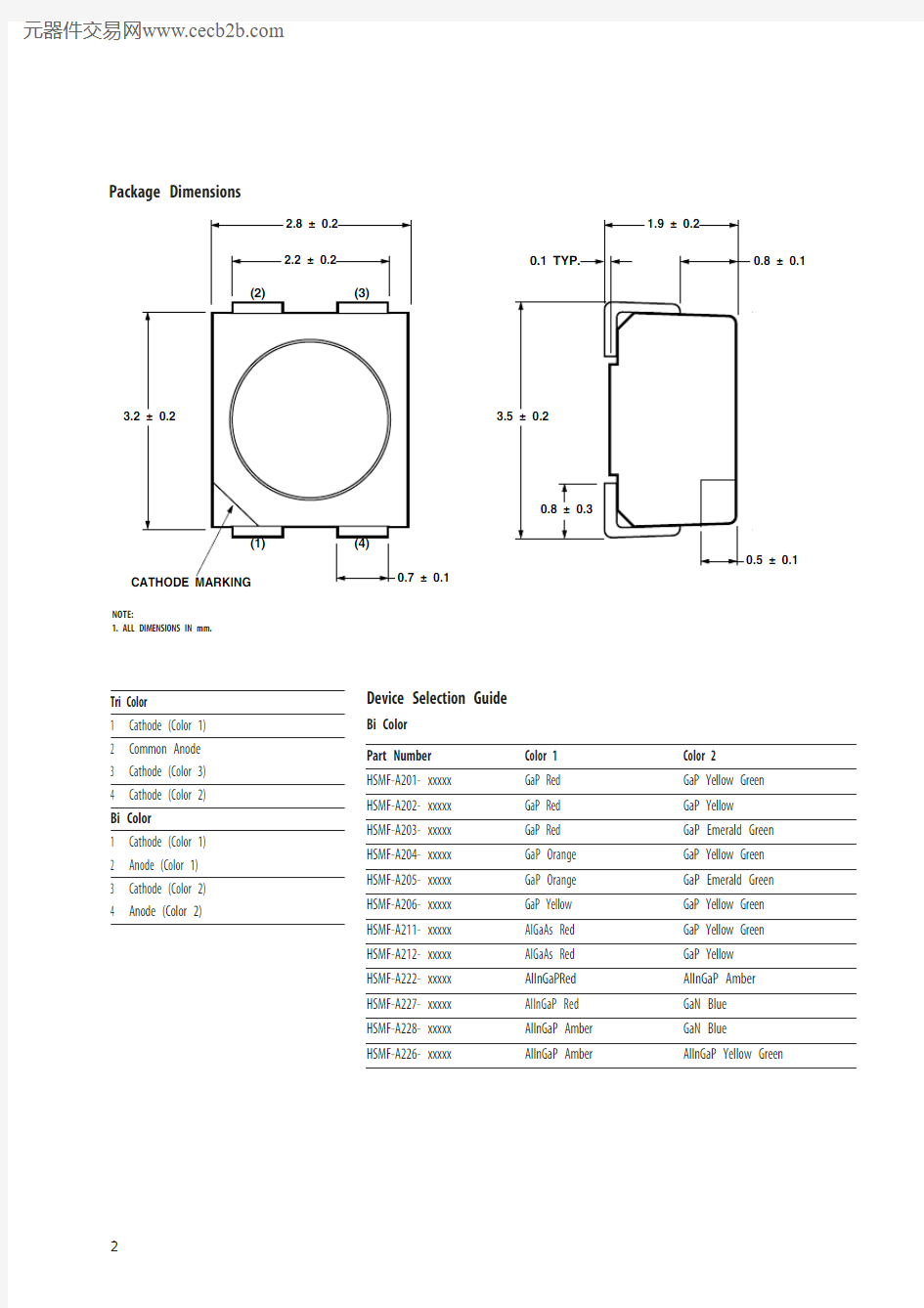
Package Dimensions
Tri Color
1 Cathode (Color 1)
2 Common Anode
3 Cathode (Color 3)
4 Cathode (Color 2) Bi Color
1 Cathode (Color 1)
2 Anode (Color 1)
3 Cathode (Color 2)
4 Anode (Color 2)
NOTE:
1. ALL DIMENSIONS IN mm.
Device Selection Guide
Bi Color Part Number Color 1 Color 2 HSMF-A201- xxxxx GaP Red GaP Yellow Green HSMF-A202- xxxxx GaP Red GaP Yellow HSMF-A203- xxxxx GaP Red GaP Emerald Green HSMF-A204- xxxxx GaP Orange GaP Yellow Green HSMF-A205- xxxxx GaP Orange GaP Emerald Green HSMF-A206- xxxxx GaP Yellow GaP Yellow Green HSMF-A211- xxxxx AlGaAs Red GaP Yellow Green HSMF-A212- xxxxx AlGaAs Red GaP Yellow HSMF-A222- xxxxx AlInGaPRed AlInGaP Amber HSMF-A227- xxxxx AlInGaP Red GaN Blue HSMF-A228- xxxxx AlInGaP Amber GaN Blue HSMF-A226- xxxxx
AlInGaP Amber
AlInGaP Yellow Green
Color 1 Color 2
Min. Iv @ 20 mA Typical Iv @ 20 mA Min. Iv @ 20 mA Typical Iv @ 20 mA
P art Number
Bin ID (mcd) (mcd) Bin ID (mcd) (mcd) H SMF-A201-A00J1 K2 8.0 16.0 L1 10.0 20.0 H SMF-A202-A00J1 K2 8.0 16.0 K1 6.3 12.0 H SMF-A203-A00J1 K2 8.0 16.0 J1 4.0 8.0 H SMF-A204-A00J1 K2 8.0 16.0 L1 10.0 20.0 H SMF-A205-A00J1 K2 8.0 16.0 J1 4.0 8.0 H SMF-A206-A00J1 K2 8.0 16.0 L1 10.0 20.0 H SMF-A211-A00J1 L2 12.5 25.0 L1 10.0 20.0 H SMF-A212-A00J1 L2 12.5 25.0 K1 6.3 12.0 H SMF-A222-A00J1 P1 40.0 80.0 P1 40.0 80.0 H SMF-A227-A00J1 P1 40.0 80.0 J2 5.0 10.0
H SMF-A228-A00J1
P1 40.0 80.0 J2 5.0 10.0 HSMF-A226-A00J1
P2
49.0
100.0
M2
20.0
60.0
Tri Color Part Number
Color 1 Color 2 Color 3
HSMF-A301-xxxxx
GaP Red GaP Yellow GreenGaN Blue HSMF-A331-xxxxx AlInGaP Red InGaN Green GaN Blue HSMF-A332-xxxxx AlInGaP Red Orange InGaN Green GaN Blue HSMF-A341-xxxxx AllnGaP Red InGaN Green InGaN Blue HSMF-A342-xxxxx
AllnGaP Red Orange
InGaN Green
InGaN Blue
Color 1
Color 2
Color 3
Min. Iv Typical Iv Min. Iv Typical Iv Min. Iv Typical Iv
@ 20 mA
@ 20 mA @ 20 mA
@ 20 mA @ 20 mA
@ 20 mA Part Number Bin ID (mcd) (mcd) Bin ID (mcd) (mcd) Bin ID (mcd) (mcd) HSMF-A301-A00J1 K2 8.0 13.0 L2 12.5 20.0 K2 8.0 10.0 HSMF-A331-A00J1 P1 40.0 80.0 R1 99.0 160.0 K2 8.0 10.0 HSMF-A332-A00J1 P1 40.0 80.0 R1 99.0 160.0 K2 8.0 10.0 HSMF-A341-A00J1 P1 40.0 80.0 R1 99.0 160.0 N1 25.0 40.0 HSMF-A342-A00J1
P1 40.0
80.0
R1 99.0
160.0
N1 25.0
40.0
Note:
1. The luminous intensity Iv, is measured at the mechanical axis of the lamp package. The actual peak of the spatial radiation pattern may not be aligned with this axis.
Note:
1. The luminous intensity Iv, is measured at the mechanical axis of the lamp package. The actual peak of the spatial radiation pattern may not be aligned with this axis.
Absolute Maximum Ratings (T A = 25°C)
AlInGaP
Parameters GaP AlGaAs Red, Amber Yellow Green GaN/InGaN DC Forward Current [1] 30 mA 30 mA 30 mA [3,4] 20 mA [4]
20 mA Peak Forward Current [2] 100 mA 100 mA 100 mA 100 mA 100 mA Power Dissipation 78 mW 78 mW 72 mW 48 mW 120 mW
Reverse Voltage 5 V Junction Temperature 110°C
Operating Temperature –55°C to +100°C
Storage Temperature –55°C to +100°C
Notes:
1. Derate linearly as shown in figure 4.
2. Duty factor = 10%, Frequency = 1kHz.
3. Drive Current between 10 mA and 30 mA are recommended for best long term performance.
4.
Operation at current below 5 mA is not recommended.
Part Numbering System
HSM x 1 – A x 2 x 3x 4 – x 5x 6 x 7 x 8x 9
Packaging Option Color Bin Selection Intensity Bin Select
Device Specification Configuration Package Type LED Chip Color
Optical Characteristics (T A = 25°C)
Peak Dominant Luminous Luminous Intensity/
Wavelength Wavelength Viewing Angle Efficacy ηv Total Flux
λPEAK (nm) λD (nm)[1]2θ1/2 (Degrees)[2](lm/W)[3]I v (mcd) /Φv (mlm) Color Typ. Typ. Typ. Typ. Typ.
GaP Red 635 626 120 120 0.45
AlGaAs Red 645 637 120 63 0.45
AlInGaP Red 635 626 120 150 0.45
AlInGaP Red Orange 621 615 120 240 0.45
GaP Orange 600 602 120 380 0.45
AlInGaP Amber 592 590 120 480 0.45
GaP Yellow 583 585 120 580 0.45
AlInGaP Amber 592 590 120 480 0.45
GaP Yellow Green 565 569 120 590 0.45
GaP Emerald Green 558 560 120 650 0.45
InGaN Green 523 525 120 500 0.45
InGaN Blue 468 470 120 75 0.45
GaN Blue 428 462 120 65 0.45
AlInGaP Yellow Green 575 571 120 620 0.45
N otes:
1. The dominant wavelength, λD, is derived from the CIE Chromaticity Diagram and represents the color of the device.
2. θ1/2 is the off-axis angle where the luminous intensity is 1/2 the peak intensity.
3. Radiant intensity, I e in watts/steradian, may be calculated from the equation I e = I v/ηv, where I v is the luminous intensity in candelas and ηv is the luminous efficacy in lumens/watt.
Electrical Characteristics (T A = 25°C)
Forward Voltage Reverse Voltage Reverse Voltage
V F (Volts) @ I F = 20mA V R @ 100 μA V R @ 10 μA
Dice Technology Typ. Max. Min. Min.
GaP 2.2 2.6 5 -
AS AlGaAs 1.9 2.6 5 -
AlInGaP 1.9 2.4 5 -
GaN Blue 3.9 4.3 - 5
InGaN 3.4 4.05 - 5
Figure 1. Relative intensity vs. wavelength.
Figure 2. Forward current vs. forward voltage.
Figure 3. Relative intensity vs. forward voltage.
Figure 4a. Maximum forward current vs. ambient temperature. Derated based on T J MAX = 110°C,
R θJA = 500°C/W (1 chip on).
FORWARD VOLTAGE – V F O R W A R D C U R R E N T – m A
HSMx-A2xx fig 2
DC FORWARD CURRENT – mA 00.41.8 R E L A T I V E L U M I N O U S I N T E N S I T Y (N O R M A L I Z E D A T
20 m A )
HSMx-A2xx fig 3
0.80.21.00.61.21.41.6C U R R E N T – m
A
TEMPERATURE – °C
HSMx-A2xx fig 4a WAVELENGTH – nm
R E L A T I V E I N T E N S I T Y
1.00.800.60.40.20.10.30.50.70.9WAVELENGTH – nm
HSMx-A2xx fig 1b
R E L A T I V E I N T E N S I T Y
1.00.80
0.60.40.2
6
N O R M A L I Z E D I N T E N S I T Y
1.00
ANGULAR DISPLACEMENT – DEGREES
0.80.60.2
0.4-70-50-3002030507090
-90-20-80-60-40-10
10406080Figure 4b. Maximum forward current vs. ambient temperature. Derated based on T J MAX = 110°C, R θJA = 700°C/W (3 chip on).Figure 5. Dominant wavelength vs. forward current
– InGaN.
Figure 6. Radiation pattern.
Figure 7. Chromaticity diagram for Tricolor.
35
0M A X I M U M F O R W A R D C U R R E N T – m A
AMBIENT TEMPERATURE – °C HSMx-A2xx fig 4b
202515
1030
5CURRENT – mA
D O M I N A N T W A V
E L E N G T H – n m
0.5
X-COORDINATE
00.20.9 Y -C O O R D I N A T E
0.9
0.40.10.50.3
0.30.60.7
0.1
0.4
0.80.70.8HSMF-A341HSMF-A342HSMF-A3310.20.6HSMF-A332HSMF-A301CIE CHART 1931
Figure 8a. Recommended SnPb reflow soldering profile.Figure 8b. Recommended Pb-free reflow soldering profile.
TIME
T E M P E R A T U R E
* THE TIME FROM 25 °C TO PEAK TEMPERATURE = 6 MINUTES MAX.
HSMx-A2xx fig 9
Figure 10. Tape leader and trailer dimension.
USER FEED DIRECTION
Figure 11. Tape leader and trailer dimension.
?1.5–0
HSMx-A2xx fig 9
Figure 12. Reel dimension.
+0–2.5
Figure 13. Reeling Orientation.
HSMx-A2xx fig 11
Moisture Sensitivity
This product is qualified as Moisture Sensitive Level 2a per Jedec J-STD-020. Precautions when handling this moisture sensitive product is important to ensure the reliability of the product. Do refer to Avago Application Note AN 0 Handling of Moisture Sensitive Surface Mount Devices for details.
A. Storage before use
- Unopen moisture barrier bag (MBB) can be stored at <40°C/ 0%RH for 12 months. If the actual shelf life has exceeded 12 months and the HIC indicates that baking is not required, then it is safe to reflow the LEDs per the original MSL rating.
- It is not recommended to open the MBB prior to assembly (e.g. for IQC).
B. Control after opening the MBB
- The humidity indicator card (HIC) shall be read immediately upon opening of MBB.
- The LEDs must be kept at < 0°C / 60%RH at all time and all high temperature related process including soldering, curing or rework need to be completed within 672 hours.
C. Control for unfinished reel
- For any unuse LEDs, they need to be stored in sealed MBB with desiccant or desiccator at < %RH.
D. Control of assembled boards
- If the PCB soldered with the LEDs is to be subjected to other high temperature processes, the PCB need to be stored in sealed MBB with desiccant or desiccator at < %RH to ensure no LEDs have exceeded their floor life of 672 hours.
E. Baking is required if:
- “10%” or “1 %” HIC indicator turns pink.
- The LEDs are exposed to condition of > 0°C / 60% RH at any time.
- The LEDs floor life exceeded 672 hours.
Recommended baking condition: 60± °C for 20 hours.
Iv Bin Select (X5X6)
Individual reel will contain parts from 1 half bin only.
X5Min. Iv Bin Selection
For
HSMF-A201-xxxxx
HSMF-A204-xxxxx
HSMF-A206-xxxxx
Minimum Intensity Bin
Color 1
(Red/Yellow/ Color 2
Orange) (Green)
A K2 L1
B K2 L2
C K2 M1
D K2 M2
E K2 N1
F L1 L1
G L1 L2
H L1 M1
J L1 M2
K L1 N1
L L2 L1
M L2 L2
N L2 M1
P L2 M2
Q L2 N1
R M1 L1
S M1 L2
T M1 M1
U M1 M2
V M1 N1
W M2 L1
X M2 L2
Y M2 M1
Z M2 M2
1 M
2 N1For
HSMF-A202-xxxxx
Minimum Intensity Bin
Color 1 Color 2
(Red) (Yellow)
A K2 K1
B K2 K2
C K2 L1
D K2 L2
E K2 M1
F L1 K1
G L1 K2
H L1 L1
J L1 L2
K L1 M1
L L2 K1
M L2 K2
N L2 L1
P L2 L2
Q L2 M1
R M1 K1
S M1 K2
T M1 L1
U M1 L2
V M1 M1
W M2 K1
X M2 K2
Y M2 L1
Z M2 L2
1 M
2 M1
For
HSMF-A203-xxxxx
HSMF-A205-xxxxx
Minimum Intensity Bin
Color 1 Color 2
(Red/Orange) (Green)
A K2 J1
B K2 J2
C K2 K1
D K2 K2
E K2 L1
F L1 J1
G L1 J2
H L1 K1
J L1 K2
K L1 L1
L L2 J1
M L2 J2
N L2 K1
P L2 K2
Q L2 L1
R M1 J1
S M1 J2
T M1 K1
U M1 K2
V M1 L1
W M2 J1
X M2 J2
Y M2 K1
Z M2 K2
1 M
2 L1
For
HSMF-A211-xxxxx
Minimum Intensity Bin
Color 1 Color 2
(Red) (Green)
A L2 L1
B L2 L2
C L2 M1
D L2 M2
E L2 N1
F M1 L1
G M1 L2
H M1 M1
J M1 M2
K M1 N1
L M2 L1
M M2 L2
N M2 M1
P M2 M2
Q M2 N1
R N1 L1
S N1 L2
T N1 M1
U N1 M2
V N1 N1
W N2 L1
X N2 L2
Y N2 M1
Z N2 M2
1 N
2 N1For
HSMF-A212-xxxxx
Minimum Intensity Bin
Color 1 Color 2
(Red) (Yellow)
A L2 K1
B L2 K2
C L2 L1
D L2 L2
E L2 M1
F M1 K1
G M1 K2
H M1 L1
J M1 L2
K M1 M1
L M2 K1
M M2 K2
N M2 L1
P M2 L2
Q M2 M1
R N1 K1
S N1 K2
T N1 L1
U N1 L2
V N1 M1
W N2 K1
X N2 K2
Y N2 L1
Z N2 L2
1 N
2 M1
For
HSMF-A222-xxxxx
Minimum Intensity Bin
Color 1 Color 2
(Red) (Amber)
A P1 P1
B P1 P2
C P1 Q1
D P1 Q2
E P1 R1
F P2 P1
G P2 P2
H P2 Q1
J P2 Q2
K P2 R1
L Q1 P1
M Q1 P2
N Q1 Q1
P Q1 Q2
Q Q1 R1
R Q2 P1
S Q2 P2
T Q2 Q1
U Q2 Q2
V Q2 R1
W R1 P1
X R1 P2
Y R1 Q1
Z R1 Q2
1 R1 R1
2 R2 P1
3 R2 P2
4 R2 Q1
5 R2 Q2
6 R2 R1
Note: 0 represents no maximum bin limit.
For
HSMF-A227-xxxxx
HSMF-A228-xxxxx
Minimum Intensity Bin
Color 1 Color 2
(Red/Amber) (Blue)
A P1 J2
B P1 K1
C P1 K2
D P1 L1
E P1 L2
F P2 J2
G P2 K1
H P2 K2
J P2 L1
K P2 L2
L Q1 J2
M Q1 K1
N Q1 K2
P Q1 L1
Q Q1 L2
R Q2 J2
S Q2 K1
T Q2 K2
U Q2 L1
V Q2 L2
W R1 J2
X R1 K1
Y R1 K2
Z R1 L1
1 R1 L2
2 R2 J2
3 R2 K1
4 R2 K2
5 R2 L1
6 R2 L2For
HSMF-A331-xxxxx
HSMF-A332-xxxxx
Minimum Intensity Bin
Color 1
(Red/Red Color 2 Color 3
Orange) (Green) (Blue)
A P1 R1 K2
B P1 R1 L1
C P1 R1 L2
D P1 R2 K2
E P1 R2 L1
F P1 R2 L2
G P1 S1 K2
H P1 S1 L1
J P1 S1 L2
K P2 R1 K2
L P2 R1 L1
M P2 R1 L2
N P2 R2 K2
P P2 R2 L1
Q P2 R2 L2
R P2 S1 K2
S P2 S1 L1
T P2 S1 L2
U Q1 R1 K2
V Q1 R1 L1
W Q1 R1 L2
X Q1 R2 K2
Y Q1 R2 L1
Z Q1 R2 L2
1 Q1 S1 K2
2 Q1 S1 L1
3 Q1 S1 L2
4 Q2 R1 K2
5 Q2 R1 L1
6 Q2 R1 L2
7 Q2 R2 K2
8 Q2 R2 L1
9 Q2 R2 L2
For
HSMF-A341-xxxxx
HSMF-A342-xxxxx
Minimum Intensity Bin
Color 1
(Red/Red Color 2 Color 3
Orange) (Green) (Blue)
A P1 R1 N1
B P1 R1 N2
C P1 R1 P1
D P1 R2 N1
E P1 R2 N2
F P1 R2 P1
G P1 S1 N1
H P1 S1 N2
J P1 S1 P1
K P2 R1 N1
L P2 R1 N2
M P2 R1 P1
N P2 R2 N1
P P2 R2 N2
Q P2 R2 P1
R P2 S1 N1
S P2 S1 N2
T P2 S1 P1
U Q1 R1 N1
V Q1 R1 N2
W Q1 R1 P1
X Q1 R2 N1
Y Q1 R2 N2
Z Q1 R2 P1
1 Q1 S1 N1
2 Q1 S1 N2
3 Q1 S1 P1
4 Q2 R1 N1
5 Q2 R1 N2
6 Q2 R1 P1
7 Q2 R2 N1
8 Q2 R2 N2
9 Q2 R2 P1
X6Number of Half bins from X5 For
HSMF-A2xx-xxxxx
Color 1 Color 2
0 0 0
A 0 5
B 0 4
C 0 3
D 0 2
E 5 0
F 5 5
G 5 4
H 5 3
J 5 2
K 4 0
L 4 5
M 4 4
N 4 3
P 4 2
Q 3 0
R 3 5
S 3 4
T 3 3
U 3 2
V 2 0
W 2 5
X 2 4
Y 2 3
Z 2 2 Note: 0 represents no maximum bin limit.For HSMF-A3xx-xxxxx
Color 1
(Red/Red Color 2 Color 3
Orange) (Green) (Blue)
0 0 0 0
A 5 5 5
B 5 5 4
C 5 5 3
D 5 4 5
E 5 4 4
F 5 4 3
G 5 3 5
H 5 3 4
J 5 3 3
K 4 5 5
L 4 5 4
M 4 5 3
N 4 4 5
P 4 4 4
Q 4 4 3
R 4 3 5
S 4 3 4
T 4 3 3
U 3 5 5
V 3 5 4
W 3 5 3
X 3 4 5
Y 3 4 4
Z 3 4 3
1 3 3 5
2 3 3 4
3 3 3 3
Intensity Bin Limits
Bin ID Min. (mcd) Max. (mcd)
J1 4.50 5.60
J2 5.60 7.20
K1 7.20 9.00
K2 9.00 11.20
L1 11.20 14.00
L2 14.00 18.00
M1 18.00 22.40
M2 22.40 28.50
N1 28.50 35.50
N2 35.50 45.00
P1 45.00 56.00
P2 56.00 71.50
Q1 71.50 90.00
Q2 90.00 112.50
R1 112.50 140.00
R2 140.00 180.00
S1 180.00 224.00
S2 224.00 285.00
T1 285.00 355.00
T2 355.00 450.00
U1 450.00 560.00
U2 560.00 715.00
V1 715.00 900.00
V2 900.00 1125.00
Tolerance of each bin limit = ±12%.
Note: 0 represents no maximum bin limit.
For
HSMF-A205-xxxxx
HSMF-A228-xxxxx
Color 1 Color 2
(Yellow/Amber/ (Emerald
Orange) Green/Blue)
0 0 0
A ABC ABC
B BCD ABC
C CDE ABC
D ABC BCD
E BCD BCD
F CDE BCD
G ABC CDE
H BCD CDE
J CDE CDE
K DEF ABC
L DEF BCD
M DEF CDE
N AB AB
P BC AB
Q CD AB
R DE AB
S AB BC
T BC BC
U CD BC
V DE BC
W AB CD
X BC CD
Y CD CD
Z DE CD
1 AB DE
2 BC DE
3 CD DE
4 DE DE
5 EF AB
6 EF BC
7 EF CD
Note: 0 represents full distribution.For
HSMF-A204-xxxxx
HSMF-A206-xxxxx
Color 1
(Yellow/
Amber/ Color 2
Orange) (Yellow Green)
0 0 0
A ABC EFG
B BCD EFG
C CDE EFG
D DEF EFG
E ABC FGH
F BCD FGH
G CDE FGH
H DEF FGH
J AB EF
K BC EF
L CD EF
M DE EF
N EF EF
P AB FG
Q BC FG
R CD FG
S DE FG
T EF FG
U AB GH
V BC GH
W CD GH
X DE GH
Y EF GH
Note: 0 represents full distribution.
Color Bin Select (X7) Individual reel will contain parts
from 1 full bin only.
X7Color Bin Combinations
For
HSMF-A202-xxxxx
HSMF-A203-xxxxx
HSMF-A212-xxxxx
HSMF-A222-xxxxx
HSMF-A227-xxxxx
Color 2
Color 1 (Emerald Green/
(Red) Yellow/Blue)
0 0 0
A 0 ABC
B 0 ABCD
C 0 ABCDE
D 0 BCD
E 0 BCDE
F 0 BCDEF
G 0 CDE
H 0 DEF
J 0 CDEF
K 0 AB
L 0 BC
M 0 CD
N 0 DE
P 0 EF
For
HSMF-A201-xxxxx
HSMF-A211-xxxxx
Color 1 Color 2
(Red) (Yellow Green)
0 0 0
A 0 EFG
B 0 FGH
C 0 EF
D 0 FG
E 0 GH
Note: 0 represents full distribution.
Note: 0 represents full distribution.
For product information and a complete list of distributors, please go to our website: https://www.doczj.com/doc/c911333332.html,
Avago, Avago Technologies, and the A logo are trademarks of Avago Technologies, Limited in the United States and other countries.Data subject to change. Copyright ? 2007 Avago Technologies Limited. All rights reserved. Obsoletes 5989-1210EN AV02-0501EN - June 13, 2007
For
HSMF-A3xx-xxxxx Color 1 Color 2 Color 30 0 0 0A 0 0 ABC B 0 0 BCD C 0 0 AB D 0 0 BC E 0 0 CD F 0 ABC 0G 0 ABC ABC H 0 ABC BCD J 0 ABC AB K 0 ABC BC L 0 ABC CD M 0 BCD 0N 0 BCD ABC P 0 BCD BCD Q 0 BCD AB R 0 BCD BC S 0 BCD CD T 0 AB ABC U 0 AB BCD V 0 AB AB W 0 AB BC X 0 AB CD Y 0 BC ABC Z 0 BC BCD 1 0 BC AB 2 0 BC BC 3 0 BC CD 4 0 CD ABC 5 0 CD BCD 6 0 CD AB 7 0 CD BC 8
CD
CD
Note: 0 represents full distribution.
Color Bin Limits
Blue Min. (nm) Max. (nm)A 460.0 465.0B 465.0 470.0C 470.0 475.0D 475.0 480.0Tolerance of each bin limit = ±1 nm.
Green Min. (nm) Max. (nm)A 515.0 520.0B 520.0 525.0C 525.0 530.0D 530.0
535.0
Emerald Green Min. (nm) Max. (nm)A 552.5 555.5B 555.5 558.5C 558.5 561.5D 561.5
564.5
Yellow Green Min. (nm) Max. (nm)E 564.5 567.5F 567.5 570.5G 570.5 573.5H
573.5
576.5
Amber/ Yellow Min. (nm) Max. (nm)A 582.0 584.5B 584.5 587.0C 587.0 589.5D 589.5 592.0E 592.0 594.5F
594.5
597.0
Orange Min. (nm) Max. (nm)A 597.0 600.0B
600.0 603.0C 603.0 606.0D 606.0 609.0E
609.0
612.0
Red Orange Min. (nm) Max. (nm)A 611.0 616.0B
616.0 620.0Red Min. (nm)
Max. (nm)
Full Distribution
Packaging Option (X 8X 9)
X 8X 9
J1 20 mA test current, Top Mount, 7 inch Reel