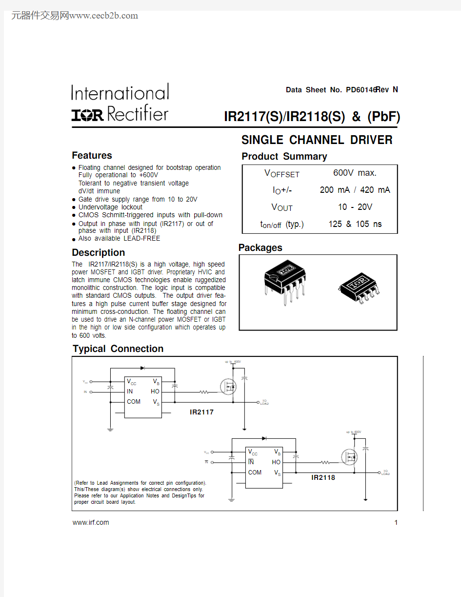
Features
Data Sheet No. PD60146 Rev N
SINGLE CHANNEL DRIVER
Product Summary
IR2117(S)/IR2118(S) & (PbF)
https://www.doczj.com/doc/c110648611.html, 1
IR2117(S)/IR2118(S) & (PbF)
2
https://www.doczj.com/doc/c110648611.html,
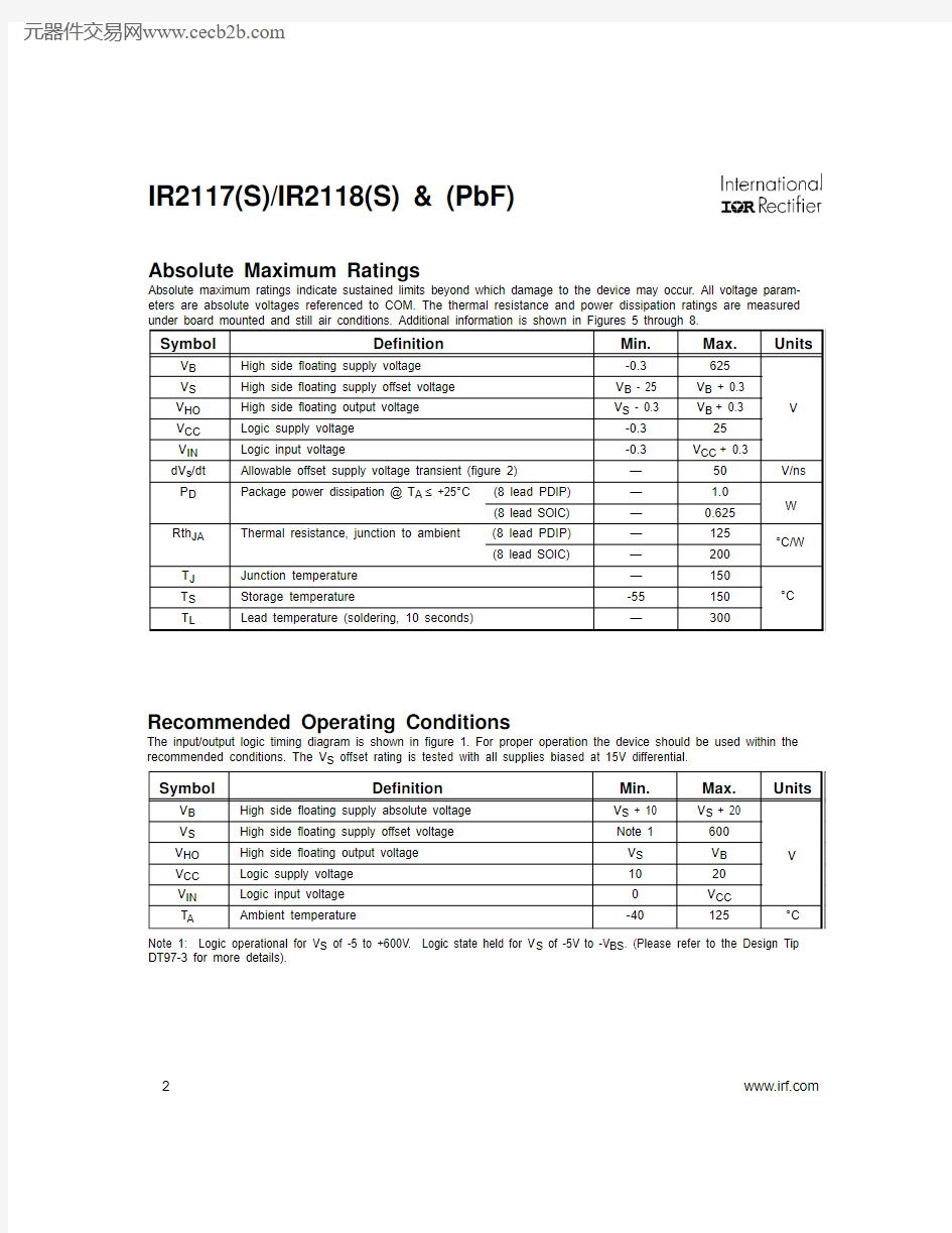
Absolute Maximum Ratings
Absolute maximum ratings indicate sustained limits beyond which damage to the device may occur. All voltage param-eters are absolute voltages referenced to COM. The thermal resistance and power dissipation ratings are measured Note 1: Logic operational for V S of -5 to +600V. Logic state held for V S of -5V to -V BS . (Please refer to the Design Tip DT97-3 for more details).
IR2117(S)/IR2118(S) & (PbF)
https://www.doczj.com/doc/c110648611.html,
3
Dynamic Electrical Characteristics
V BIAS (V CC , V BS ) = 15V, C L = 1000 pF and T A = 25°C unless otherwise specified. The dynamic electrical characteristics are measured using the test circuit shown in Figure 3.
Static Electrical Characteristics
V BIAS (V CC , V BS ) = 15V and T A = 25°C unless otherwise specified. The V IN , V TH and I IN parameters are referenced to COM. The V O and I O parameters are referenced to COM and are applicable to the respective output leads: HO or LO.
IR2117(S)/IR2118(S) & (PbF) 4
https://www.doczj.com/doc/c110648611.html,
Functional Block Diagram (IR2118)
IR2117(S)/IR2118(S) & (PbF)
https://www.doczj.com/doc/c110648611.html,
5
Symbol
Description
V CC Logic and gate drive supply
IN
Logic input for gate driver output (HO), in phase with HO (IR2117)IN Logic input for gate driver output (HO), out of phase with HO (IR2118)COM Logic ground
V B High side floating supply HO High side gate drive output V S
High side floating supply return
Lead Assignments
8 Lead PDIP 8 Lead SOIC
IR2118IR2118S
1234
8
765
V CC IN COM
V B HO V
S
1234
8
765
V CC IN COM
V B HO V S
8 Lead PDIP 8 Lead SOIC
IR2117IR2117S
1234
8
765
V CC IN COM
V B HO V S
1234
8
765
V CC IN COM
V B HO V S
IR2117(S)/IR2118(S) & (PbF)
6
https://www.doczj.com/doc/c110648611.html,
IR2117/IR2118
Figure 2. Floating Supply Voltage Transient Test Circuit
IN
(IR2117)
HO
IN
(IR2118)
IR2117/IR2118
<50 V/ns
IR2117(S)/IR2118(S) & (PbF)
https://www.doczj.com/doc/c110648611.html,
7
IR2117(S)/IR2118(S) & (PbF)
8
https://www.doczj.com/doc/c110648611.html,
IR2117(S)/IR2118(S) & (PbF)
https://www.doczj.com/doc/c110648611.html,
9
IR2117(S)/IR2118(S) & (PbF)
10
https://www.doczj.com/doc/c110648611.html,
IR2117(S)/IR2118(S) & (PbF)
https://www.doczj.com/doc/c110648611.html,
11
(A (A V S (
)V S (
)
IR2117(S)/IR2118(S) & (PbF)
12
https://www.doczj.com/doc/c110648611.html,
(A (
)
(
)
(
)
IR2117(S)/IR2118(S) & (PbF)
https://www.doczj.com/doc/c110648611.html,
13
()
t (
)
(
) (
)
IR2117(S)/IR2118(S) & (PbF)
14
https://www.doczj.com/doc/c110648611.html,
(
) (
)V S (
)
()
IR2117(S)/IR2118(S) & (PbF)
https://www.doczj.com/doc/c110648611.html,
15
t ()
t ()
IR2117(S)/IR2118(S) & (PbF)
16
https://www.doczj.com/doc/c110648611.html,
0255075
1001251501E+2
1E+3
1E+41E+5
1E+6
Frequency (Hz)
J u n c t i o n T e m p e r a t u r e (°C )
320V
140V
10V
255075100
1251501E+21E+31E+41E+51E+6
Frequency (Hz)
J u n c t i o n T e m p e r a t u r e (°C )
320V 140V
10V
02550751001251501E+2
1E+3
1E+41E+5
1E+6Frequency (Hz)
J u n c t i o n T e m p e r a t u r e (°C )
320V 140V 10V
2550751001251501E+21E+31E+41E+51E+6
Frequency (Hz)
J u n c t i o n T e m p e r a t u r e (°C )
320V 140V
10V
Case outlines
IR2117(S)/IR2118(S) & (PbF)
18
https://www.doczj.com/doc/c110648611.html,
Per SCOP 200-002
IR WORLD HEADQUARTERS: 233 Kansas St., El Segundo, California 90245 Tel: (310) 252-7105
This product has been qualified per industrial level
Data and specifications subject to change without notice. 4/2/2004