毕业设计(论文)外文资料翻译
系别:电子信息系
专业:通信工程
班级:B100309
姓名:张杨
学号:B10030942
外文出处:
附件: 1. 原文; 2. 译文
2014年03月
An Introduction to the ARM 7 Architecture
Trevor Martin CEng, MIEE
Technical Director
This article gives an overview of the ARM 7 architecture and a description of its major features for a developer new to the device. Future articles will examine other aspects of the ARM architecture.
Basic Characteristics
The principle feature of the ARM 7 microcontroller is that it is a register based load-and-store architecture with a number of operating modes. While the ARM7 is a 32 bit microcontroller, it is also capable of running a 16-bit instruction set, known as "THUMB". This helps it achieve a greater code density and enhanced power saving. While all of the register-to-register data processing instructions are single-cycle, other instructions such as data transfer instructions, are multi-cycle. To increase the performance of these instructions, the ARM 7 has a three-stage pipeline. Due to the inherent simplicity of the design and low gate count, ARM 7 is the industry leader in low-power processing on a watts per MIP basis. Finally, to assist the developer, the ARM core has a built-in JTAG debug port and on-chip "embedded ICE" that allows programs to be downloaded and fully debugged in-system.
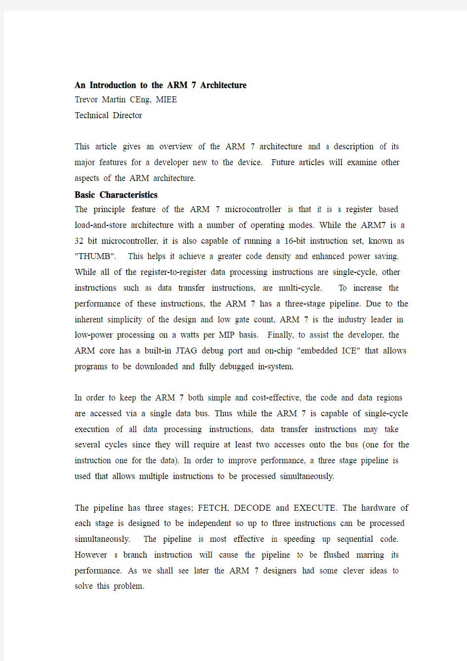
In order to keep the ARM 7 both simple and cost-effective, the code and data regions are accessed via a single data bus. Thus while the ARM 7 is capable of single-cycle execution of all data processing instructions, data transfer instructions may take several cycles since they will require at least two accesses onto the bus (one for the instruction one for the data). In order to improve performance, a three stage pipeline is used that allows multiple instructions to be processed simultaneously.
The pipeline has three stages; FETCH, DECODE and EXECUTE. The hardware of each stage is designed to be independent so up to three instructions can be processed simultaneously. The pipeline is most effective in speeding up sequential code. However a branch instruction will cause the pipeline to be flushed marring its performance. As we shall see later the ARM 7 designers had some clever ideas to solve this problem.
Instruction
Fig 1 ARM 3- Stage pipeline
ARM7 Programming Model
The programmer's model of the ARM 7 consists of 15 user registers, as shown in Fig. 3, with R15 being used as the Program Counter (PC). Since the ARM 7 is a load-and- store architecture, an user program must load data from memory into the CPU registers, process this data and then store the result back into memory. Unlike other processors no memory to memory instructions are available.
M1
M2
M3
4
,R1,R2 (R4=R0+R2)3
Fig 2 Load And Store Architecture
As stated above R15 is the Program Counter. R13 and R14 also have special functions; R13 is used as the stack pointer, though this has only been defined as a programming convention. Unusually the ARM instruction set does not have PUSH and POP instructions so stack handling is done via a set of instructions that allow loading and storing of multiple registers in a single operation. Thus it is possible to PUSH or POP the entire register set onto the stack in a single instruction. R14 has special significance and is called the "link register". When a call is made to a procedure, the return address is automatically placed into R14, rather than onto a stack, as might be expected. A return can then be implemented by moving the contents of R14 into
R15, the PC. For multiple calling trees, the contents of R14 (the link register) must be placed onto the stack.
15 User registers +PC
R13 is used as the stack pointer R14 is the link register
R14 is the Program Counter Current Program Status Register
Fig 3 User Mode Register Model
In addition to the 16 CPU registers, there is a current program status register (CPSR). This contains a set of condition code flags in the upper four bits that record the result of a previous instruction, as shown in Fig 4. In addition to the condition code flags, the CPSR contains a number of user-configurable bits that can be used to change the processor mode, enter Thumb processing and enable/disable interrupts.
31 30 29 28 27Negative Carry Overflow
IRQ System User
Undefined instruction Abort
Thumb instruction set
Fig 4 Current Program Status Register and Flags Exception And Interrupt Modes
The ARM 7 architecture has a total of six different operating modes, as shown below. These modes are protected or exception modes which have associated interrupt
sources and their own register sets.
User: This mode is used to run the application code. Once in user mode the CPSR cannot be written to and modes can only be changed when an exception is generated. FIQ: (Fast Interrupt reQuest) This supports high speed interrupt handling. Generally it is used for a single critical interrupt source in a system
IRQ: (Interrupt ReQuest) This supports all other interrupt sources in a system Supervisor: A "protected" mode for running system level code to access hardware or run OS calls. The ARM 7 enters this mode after reset
Abort: If an instruction or data is fetched from an invalid memory region, an abort exception will be generated
Undefined Instruction:If a FETCHED opcode is not an ARM instruction, an undefined instruction exception will be generated.
The User registers R0-R7 are common to all operating modes. However FIQ mode has its own R8 -R14 that replace the user registers when FIQ is entered. Similarly, each of the other modes have their own R13 and R14 so that each operating mode has its own unique Stack pointer and Link register. The CPSR is also common to all modes. However in each of the exception modes, an additional register一the saved program status register (SPSR),is added. When the processor changes the current value of the CPSR stored in the SPSR,this can be restored on exiting the exception mode.
System&User FIQ Supervisor Abort IRQ Undefined Fig 5 Full Register Set For ARM 7
Entry to the Exception modes is through the interrupt vector table. Exceptions in the ARM processor can be split into three distinct types.
(i) Exceptions caused by executing an instruction, these include software interrupts, undefined instruction exceptions and memory abort exceptions
(ii) Exceptions caused as a side effect of an instruction such as a abort caused by trying to fetch data from an invalid memory region.
(iii) Exceptions unrelated to instruction execution, this includes reset, FIQ and IRQ interrupts.
In each case entry into the exception mode uses the same mechanism. On generation of the exception, the processor switches to the privileged mode, the current value of the PC+4 is saved into the Link register (R14) of the privileged mode and the current value of CPSR is saved into the privileged mode's SPSR. The IRQ interrupts are also disabled and if the FIQ mode is entered, the FIQ interrupts are also disabled, Finally the Program Counter is forced to the exception vector address and processing of the exception can start. Usually the first action of the exception routine will be to push
Prefetch Abort(instruction fetch memory abort)Software interrupt (SWI)
Undefined instruction Reset
Data Abort (data access momory abort)IRQ (interrupt)FIQ (fast interrupt)
Supervisor Undefined Supervisor Abort Abort IRQ FIQ
0x000000000x0000001C
0x000000040x0000000C 0x000000080x000000100x00000018Fig 6 ARM 7 Vector Table
A couple of things are worth noting on the vector table. Firstly, there is a missing vector at 0x000000014. This was used on an earlier ARM architecture and is left empty on ARM 7 to allow backward compatibility. Secondly, the FIQ interrupt is at the highest address so the FIQ routines could start from this address, removing the need for a jump instruction to reach the routine. It helps make entry into the FIQ routine as fast as possible.
Once processing of the exception has finished, the processor can leave the privileged mode and return to the user mode. Firstly the contents of any registers previously saved onto the stack must be restored. Next the CSPR must be restored from the SPSR and finally the Program Counter is restored by moving the contents of the link register to R15, (i.e. the Program Counter). The interrupted program flow can then restart.
Data Types
The ARM instruction set supports six data types namely 8 bit signed and unsigned, 16 bit signed and unsigned plus 32 bit signed and unsigned. The ARM processor instruction set has been designed to support these data types in Little or Big-endian formats. However most ARM silicon implementations use the Little-endian format. ARM instructions typically have a three-operand format, as shown below
ADD Rl,R2, R3 ; Rl=R2+R3
ARM7 Program Flow Control
In all processors there is a small group of instructions that are conditionally executed depending on a group of processor flags. These are branch instructions such as branch not equal. Within the ARM instruction set, all instructions are conditionally executable.
31 28
COND
Fig. 7 Instruction Condition Code Bits
The top four bits of each instruction contain a condition code that must be satisfied if the instruction is to be executed. This goes a long way to eliminating small branches in the program code and eliminating stalls in the pipeline so increasing the overall program performance. Thus for small conditional branches of three instructions or less, conditional execution of instructions should be used. For larger jumps, normal branching instructions should be used.
Fig. 8 Instruction Condition Codes
Thus our ADD instruction below could be prefixed with a condition code, as shown. This adds no overhead to instruction execution
EQADD R1,R2,R3 ;If(Zero flag = 1)then R1 = R2+R3
The ARM7 processor also has a 32-bit barrel shifter that allows it to shift or rotate one of the operands in a data processing instruction. This takes place in the same cycle as the instruction. The ADD instruction could be expanded as follows
EQADD R1,R2 R3,LSL #2 ; If ( Zero flag = 1) then R1 = R2+ (R3 x 4) Finally the programmer may decide if a particular instruction can set the condition code flags in the CPSR.
EQADDS R1,R2 R3,LSL #2; If (Zero flag = 1) then R1 = R2 + (R3 x4)and set condition code flags
In the ARM instruction set there are no dedicated call or return instructions. Instead these functions are created out of a small group of branching instructions.
The standard branch (B) instruction allows a jump of around+-32Mb. A conditional branch can be formed by use of the condition codes. For example, a "branch not
equal" would be the branching instruction B and the condition code "NE" for not equal giving "BNE". The next form of the branch instruction is the branch with link. This is the branch instruction but the current value of the PC +4 is saved into R14, the link register. This acts as a CALL instruction by saving the return address into R14. A return instruction is not necessary since a return can be implemented by moving R14 into the PC. The return is more complicated in the case of an interrupt routine. Depending on the type of exception, it may be necessary to modify the contents of the link register to get the correct return address. For example, in the case of an IRQ or FIQ interrupt, the processor will finish its current instruction, increment the PC to the next instruction and then jumping to the vector table. This means that the value in the link register is PC+4 or one instruction ahead of the return address. This means we need to subtract 4 from the value in the link register to get the correct return address. This can be done in a single instruction thus: SUBS pc, r14, #4// PC=Link register-4
0x8000
0x400PC=0x80000x4000x8000
Fig 9 Branch and Branch Link Instruction Operation
Branching instructions are also used to enter the 16-bit Thumb instruction set. Both the branch and branch-with-link may perform an exchange between 32-bit and 16-bit instruction sets and vice versa .
The Branch exchange will jump to a location and start to execute 16-bit Thumb instructions. Branch link exchange will jump to a location, save PC+4 into the link register and start execution of 16-bit Thumb instructions. In both cases, the T bit is set in the CPSR. An equivalent instruction is implemented in the Thumb instruction set to return to 32-bit ARM instruction processing.
0x8000
T=1
Y=1
0x400
0x400
0x8000
Fig. 10 Branch Exchange and Branch Link Exchange Instruction Operation Software Interrupts
The ARM instruction set has a software interrupt instruction. Execution of this
instruction forces an exception as described above; the processor will enter supervisor mode and jump to the SWI vector at 0x00000008.
Fig. 11 Software Interrupt Instruction
The bit field 0-23 of the SWI instruction is empty and can be used to hold an ordinal. On execution of an SWI instruction, this ordinal can be examined to determine which SWI procedure to run and gives over 16 million possible SWI functions.
…
Swi_ #1 . call swi function one
…
Tn the swi handler
register unsigned*link ptr asm ("r14");// define a pointer to the hnk register Switch ((*(link-ptr-1))&Ox00FFFFFF) //calculate the number of the swi function
{
Case 0x01 : SWI_unction (); //Call the function
…
}
This can be used to provide a hardware abstraction layer. In order to access OS calls or SFR registers, the user code must make a SWI call . All these functions are the
running in a supervisor mode, with a separate stack and link register.
As well as instructions to transfer data to and from memory and to CPU registers, the ARM 7 has instructions to save and load multiple registers. It is possible to load or save all 16 CPU registers or a selection of registers in a single instruction. Needless to
say, this is extremely useful when entering or exiting a procedure.
M0
Fig. 12 Load and Store Multiple Instruction Operation
The CPSR and SPSR are only accessed by two special instructions to move their contents to and from a CPU register. No other instruction can act on them directly.
MSR
MRS
R15
R15
Fig. 13 Programming The SPSR And CPSR Registers
THUMB Support
The ARM processor is capable of executing both 32-bit (ARM) instructions and 16- Bit (Thumb instructions). The Thumb instruction set must always be entered by
running a Branch exchange or branch link exchange instruction and NOT by setting the T bit in the CPSR. Thumb instructions are essentially a mapping of their 32 bit cousins but unlike the ARM instructions, they are unconditionally executed except though for branch instructions.
Fig. 14 Thumb Instruction Processing
Thumb instructions reduced number of only have unlimited access to registers RO-R7 and R13一Rl5. A instructions can access the full register set.
Fig.15 Thumb programmers model
The Thumb instruction set has the same load and store multiple instructions as ARM and in addition, has a modified version of these instructions in the form of PUSH and POP that implement a full descending stack in the conventional manner. The Thumb instruction set also supports the SWI instruction, except that the ordinal field is only 8 bits long to support 256 different SWI calls. When the processor is executing Thumb code and an exception occurs, it will switch to ARM mode in order to process the exception. When the CPSR is restored the, Thumb bit will be reset and the processor continues to run Thumb instructions.
BCX
BX
Fig.16 Thumb Exception Processing
Thumb has a much higher code density than ARM code, needing some 70% of the space of the latter. However in a 32-bit memory, ARM code is some 40% faster than Thumb. However it should be noted that if you only have 16-bit wide memory then Thumb code will be faster than ARM code by about 45%. Finally the other important aspect of Thumb is that it can use up to 30% less power than ARM code.
ARM7的体系结构介绍
特里沃马丁曾,鼠
技术总监
本文给出了ARM 7架构的概述和开发新的设备,以及主要功能的描述,未来将研究ARM体系结构的其他方面。
基本特点
ARM7单片机原理的特点是,它是一个基于寄存器的加载和存储与多个操作模式的体系结构。ARM7是一个32位单片机,它也能够运行16位指令集,被称为“拇指”。这有助于实现一个更大的代码密度和加强节能。而所有的寄存器到寄存器的数据处理的指令都是单周期指令,如数据传送指令,多周期。增加这些指令的性能,ARM7具有三级管道。由于与低门数设计的固有的简单性,ARM7的低功耗处理在瓦/ MIP基础行业是领导者。最后,以协助开发,ARM内核有一个内置的JTAG调试端口和芯片上的“嵌入式冰”,允许程序被下载和全面调试系统。
为了保持ARM既简单又划算,代码和数据区域通过单数据总线访问。因此ARM7能够单循环执行所有的数据处理指令,数据传送指令可能需要几个周期,因为他们将需要至少两个访问总线(一个是指令一个是数据)。为了提高性能,三个管道被用于允许多个指令同时处理。这个管道有三个阶段:接收,编译,执行。每一个阶段的硬件设计是独立的,三个指令能够同时地被执行。在迅速上升的连续代码中,此管道是最有效的。然而一个分支指令会导致管道的性能被破坏。我们必须看到后来的ARM7设计师提出一些聪明的办法来解决这些事情。
指令
图1 ARM7的三个阶段管道
ARM 7程序设计模型
程序设计员的ARM7模型由15个用户寄存器组成,如图3所示,R15被用做为程序设计器,自从ARM7作为下载和存储建筑学以后,用户程序必须从CPU 暂存器下载数据,执行的数据和存储的结果返回到寄存器,不像其他的处理器没有记忆存储器指令可用。
图4 当前程序状态注册和标记
异常和中断模式
ARM7体系结构模式有总数为6个不同的运行模式,如下面所示。这些模式被保护或者异常模式有相关的中断源和自己的寄存器组。
用户模式:这个模式是用于运行代码应用。一旦在用户模式下的操作不能被写入和模式只能改变时,生成一个异常。
快速中断模式:支持高速全速中断处理,通常在系统中用作单信号临界中断源。 外部中断模式:支持系统中的所有中断源。
管理模式:运行系统级别的代码访问硬件或者操作系统调用运行“保护”模式。ARM7复位后进入此模式。
数据访问终止模式:如果一条命令或者数据从无效的记忆区域中取出,异常终止便产生。
未定义指令:如果接收的操作码不是ARM 指令,未定义的指令异常就会产生。
用户寄存器R0-R7对所有的运行模式都是相同的。然而当进入快速中断模式后,快速中断模式有自己的R8-R14来代替用户寄存器。同样地,其他模式相互间有自己的R13和R14,以至于每一个运行模式有自己的唯一的堆栈指针和环节注册。CPSR 对所有的模式共用。然而在每一个异常模式,额外的注册—已保存的程序状态寄存器,被添加了。当处理器改变当前的CPSR ,保存在SPSR ,可以从异常模式中修复。
31 30 29 28 27复数携带溢出
系统用户
未定义指令中止
ARM指令系统支持6种数据类型,也就是8位有符号和无符号,16位有符号和无符号,加上32位有符号和无符号。ARM处理器指令系统设计的目的在于在小规模地或者大端法的格式支持这些数据类型,然而大多数的ARM硅安装启用的是小端格式。
ARM指令典型地有三大操作格式,如下所示
ADD R1,R2,R3;R1=R2+R3
ARM7程序流控制
在所有的处理器有一个小组,有条件的执行取决于一组处理器标志指示。这些分支指令,比如分支不相等。在ARM指令系统中,所有的指令都是有条件的执行。
31 28
COND
图7 指令条件码位
每个指令的前四位包含条件代码,如果要执行,指令必须满足。这有助于消除程序中的小树枝和消除摊点管道,增加整体程序的性能。从而为三个或更少的
小条件分支指令,有条件指令的执行必须被用到。对于较大的跳跃,应该用正常的分支指令。
图8 指令条件代码
因此,我们添加下面的指令可能条件码前缀,如下所示。这增加了没有指令执行的开销
EQADD R1,R2,R3 ;If(Zero flag = 1)then R1 = R2+R3
ARM处理器同样有一个32位的柱式移位器,在数据处理指令中允许转移或循环其中一个操作数。这发生在和指令相同的循环。加法指令可以如下扩展EQADD R1,R2 R3,LSL #2 ; If ( Zero flag = 1) then R1 = R2+ (R3 x 4) 最后的程序设计员可能决定在CPSR中如果特定的指令可以设置状态码标志。
EQADDS R1,R2 R3,LSL #2; If (Zero flag = 1) then R1 = R2 + (R3 x4) and set condition code flags
ARM指令系统没有专用的调用指令或者返回指令,相反,这些功能都是从一个小群体的分支指令创建。
标准的分支(B)指令允许在+-32Mb范围内的跳跃。条件分支可以通过利用条件代码形成。例如,“分支不相等”将分支指令B和条件代码“NE”不等于给“BNE”,下一个分支指令的形式是链接分支。
这是分支指令,但是PC+4的当前值保存在R14,链接注册。充当的是CALL
指令,保存返回地址到R14。在PC 中,自返回被执行,保存返回地址到R14,返回指令不是必须的。在中断程序下,返回指令会越来越复杂。根据异常的类型,可能需要修改链接寄存器的内容得到正确的返回地址。例如,在IRQ 或者FIQ 中断的情况下,该处理器将会完成当前指令,增加电脑到下一个指令,然后跳到矢量表。这意味着链接注册的价值是PC+4,或者在返回地址前的一个指令。这意味着我们需要从链接注册的值中减4,获得当前返回地址。如下所示
SUBS pc, r14, #4// PC=Link register-4
0x8000
0x400PC=0x8000
0x4000x8000
图9 分支和分支链接指令操作
分支指令也同样被用在进入16位拇指指令系统。分支和带链接的分支可能执行一个交流32位和16位指令集,反之亦然。
分支链路交换将会跳转到一个位置,并开始执行16位的拇指指令。分支链接交换将会跳转到一个位置,将PC+4保存到链接注册,并开始执行16位的拇指指令。在这两种情况下,CPSR 发生在CPSR 。拇指的等效指令实现指令集回到32位ARM 指令处理。
0x8000
T=1
Y=1
0x400
0x400
0x8000
图 10 分支交换和分支链接交换指令操作
广东工业大学华立学院 本科毕业设计(论文) 外文参考文献译文及原文 系部经济学部 专业经济学 年级 2007级 班级名称 07经济学6班 学号 16020706001 学生姓名张瑜琴 指导教师陈锶 2011 年05月
目录 1挑战:小额贷款中的进入和商业银行的长期承诺 (1) 2什么商业银行带给小额贷款和什么把他们留在外 (2) 3 商业银行的四个模型进入小额贷款之内 (4) 3.1内在的单位 (4) 3.2财务子公司 (5) 3.3策略的同盟 (5) 3.4服务公司模型 (6) 4 合法的形式和操作的结构比较 (8) 5 服务的个案研究公司模型:厄瓜多尔和Haiti5 (9)
1 挑战:小额贷款中的进入和商业银行的长期承诺 商业银行已经是逐渐重要的运动员在拉丁美洲中的小额贷款服务的发展2到小额贷款市场是小额贷款的好消息客户因为银行能提供他们一完整类型的财务的服务,包括信用,储蓄和以费用为基础的服务。整体而言,它也对小额贷款重要,因为与他们广泛的身体、财务的和人类。如果商业银行变成重的运动员在小额贷款,他们能提供非常强烈的竞争到传统的小额贷款机构。资源,银行能廉宜地发射而且扩张小额贷款服务rela tively。如果商业广告银行在小额贷款中成为严重的运动员,他们能提出非常强烈的竞争给传统的小额贷款机构。然而,小额贷款社区里面有知觉哪一商业银行进入进入小额贷款将会是短命或浅的。举例来说,有知觉哪一商业银行首先可能不搬进小额贷款因为时候建立小额贷款操作到一个有利润的水平超过银行的标准投资时间地平线。或,在进入小额贷款,银行之后可能移动在-上面藉由增加贷款数量销售取利润最大值-或者更坏的事,退出如果他们是不满意与小额贷款的收益性的水平。这些知觉已经被特性加燃料商业银行的情形进入小额贷款和后来的出口之内。在最极端的,一些开业者已经甚至宣布,”降低尺度死!”而且抛弃了与主意合作的商业银行。 在最 signific 看得到的地方,蚂蚁利益商业银行可能带给小额贷款,国际的ACCION 发展发射而且扩张的和一些商业银行的关系小额贷款操作。在这些情形的大部分方面, ACCION 和它的合伙人正在使用方法,已知的当做服务公司模型,表演早答应当做一个能工作的方法克服真正的。 商业银行的障碍进入和穿越建立长命的小额贷款操作一个商业银行 这论文描述如何服务公司模型、住址商业银行中的主要议题进入进小额贷款,监定成功建立的因素动作井小额贷款服务公司,和礼物结果和小额贷款的课servic e 公司用最长的经验,在海地和审判官席 del 的 SOGEBANK│ SOGESOL 初期结果指出那这服务公司模型表现一重要的突破在促成商业银行进入和留在小额贷款。在厄瓜多尔的 Pichincha│ CREDIFE。初期结果指出服务公司模型在促成商业广告中表现一次重要的突破银行进入而且留在小额贷款。
外文出处: 《Exploiting Software How to Break Code》By Greg Hoglund, Gary McGraw Publisher : Addison Wesley Pub Date : February 17, 2004 ISBN : 0-201-78695-8 译文标题: JDBC接口技术 译文: JDBC是一种可用于执行SQL语句的JavaAPI(ApplicationProgrammingInterface应用程序设计接口)。它由一些Java语言编写的类和界面组成。JDBC为数据库应用开发人员、数据库前台工具开发人员提供了一种标准的应用程序设计接口,使开发人员可以用纯Java语言编写完整的数据库应用程序。 一、ODBC到JDBC的发展历程 说到JDBC,很容易让人联想到另一个十分熟悉的字眼“ODBC”。它们之间有没有联系呢?如果有,那么它们之间又是怎样的关系呢? ODBC是OpenDatabaseConnectivity的英文简写。它是一种用来在相关或不相关的数据库管理系统(DBMS)中存取数据的,用C语言实现的,标准应用程序数据接口。通过ODBCAPI,应用程序可以存取保存在多种不同数据库管理系统(DBMS)中的数据,而不论每个DBMS使用了何种数据存储格式和编程接口。 1.ODBC的结构模型 ODBC的结构包括四个主要部分:应用程序接口、驱动器管理器、数据库驱动器和数据源。应用程序接口:屏蔽不同的ODBC数据库驱动器之间函数调用的差别,为用户提供统一的SQL编程接口。 驱动器管理器:为应用程序装载数据库驱动器。 数据库驱动器:实现ODBC的函数调用,提供对特定数据源的SQL请求。如果需要,数据库驱动器将修改应用程序的请求,使得请求符合相关的DBMS所支持的文法。 数据源:由用户想要存取的数据以及与它相关的操作系统、DBMS和用于访问DBMS的网络平台组成。 虽然ODBC驱动器管理器的主要目的是加载数据库驱动器,以便ODBC函数调用,但是数据库驱动器本身也执行ODBC函数调用,并与数据库相互配合。因此当应用系统发出调用与数据源进行连接时,数据库驱动器能管理通信协议。当建立起与数据源的连接时,数据库驱动器便能处理应用系统向DBMS发出的请求,对分析或发自数据源的设计进行必要的翻译,并将结果返回给应用系统。 2.JDBC的诞生 自从Java语言于1995年5月正式公布以来,Java风靡全球。出现大量的用java语言编写的程序,其中也包括数据库应用程序。由于没有一个Java语言的API,编程人员不得不在Java程序中加入C语言的ODBC函数调用。这就使很多Java的优秀特性无法充分发挥,比如平台无关性、面向对象特性等。随着越来越多的编程人员对Java语言的日益喜爱,越来越多的公司在Java程序开发上投入的精力日益增加,对java语言接口的访问数据库的API 的要求越来越强烈。也由于ODBC的有其不足之处,比如它并不容易使用,没有面向对象的特性等等,SUN公司决定开发一Java语言为接口的数据库应用程序开发接口。在JDK1.x 版本中,JDBC只是一个可选部件,到了JDK1.1公布时,SQL类包(也就是JDBCAPI)
大数据外文翻译参考文献综述 (文档含中英文对照即英文原文和中文翻译) 原文: Data Mining and Data Publishing Data mining is the extraction of vast interesting patterns or knowledge from huge amount of data. The initial idea of privacy-preserving data mining PPDM was to extend traditional data mining techniques to work with the data modified to mask sensitive information. The key issues were how to modify the data and how to recover the data mining result from the modified data. Privacy-preserving data mining considers the problem of running data mining algorithms on confidential data that is not supposed to be revealed even to the party
running the algorithm. In contrast, privacy-preserving data publishing (PPDP) may not necessarily be tied to a specific data mining task, and the data mining task may be unknown at the time of data publishing. PPDP studies how to transform raw data into a version that is immunized against privacy attacks but that still supports effective data mining tasks. Privacy-preserving for both data mining (PPDM) and data publishing (PPDP) has become increasingly popular because it allows sharing of privacy sensitive data for analysis purposes. One well studied approach is the k-anonymity model [1] which in turn led to other models such as confidence bounding, l-diversity, t-closeness, (α,k)-anonymity, etc. In particular, all known mechanisms try to minimize information loss and such an attempt provides a loophole for attacks. The aim of this paper is to present a survey for most of the common attacks techniques for anonymization-based PPDM & PPDP and explain their effects on Data Privacy. Although data mining is potentially useful, many data holders are reluctant to provide their data for data mining for the fear of violating individual privacy. In recent years, study has been made to ensure that the sensitive information of individuals cannot be identified easily. Anonymity Models, k-anonymization techniques have been the focus of intense research in the last few years. In order to ensure anonymization of data while at the same time minimizing the information
外文翻译 专业机械设计制造及其自动化学生姓名刘链柱 班级机制111 学号1110101102 指导教师葛友华
外文资料名称: Design and performance evaluation of vacuum cleaners using cyclone technology 外文资料出处:Korean J. Chem. Eng., 23(6), (用外文写) 925-930 (2006) 附件: 1.外文资料翻译译文 2.外文原文
应用旋风技术真空吸尘器的设计和性能介绍 吉尔泰金,洪城铱昌,宰瑾李, 刘链柱译 摘要:旋风型分离器技术用于真空吸尘器 - 轴向进流旋风和切向进气道流旋风有效地收集粉尘和降低压力降已被实验研究。优化设计等因素作为集尘效率,压降,并切成尺寸被粒度对应于分级收集的50%的效率进行了研究。颗粒切成大小降低入口面积,体直径,减小涡取景器直径的旋风。切向入口的双流量气旋具有良好的性能考虑的350毫米汞柱的低压降和为1.5μm的质量中位直径在1米3的流量的截止尺寸。一使用切向入口的双流量旋风吸尘器示出了势是一种有效的方法,用于收集在家庭中产生的粉尘。 摘要及关键词:吸尘器; 粉尘; 旋风分离器 引言 我们这个时代的很大一部分都花在了房子,工作场所,或其他建筑,因此,室内空间应该是既舒适情绪和卫生。但室内空气中含有超过室外空气因气密性的二次污染物,毒物,食品气味。这是通过使用产生在建筑中的新材料和设备。真空吸尘器为代表的家电去除有害物质从地板到地毯所用的商用真空吸尘器房子由纸过滤,预过滤器和排气过滤器通过洁净的空气排放到大气中。虽然真空吸尘器是方便在使用中,吸入压力下降说唱空转成比例地清洗的时间,以及纸过滤器也应定期更换,由于压力下降,气味和细菌通过纸过滤器内的残留粉尘。 图1示出了大气气溶胶的粒度分布通常是双峰形,在粗颗粒(>2.0微米)模式为主要的外部来源,如风吹尘,海盐喷雾,火山,从工厂直接排放和车辆废气排放,以及那些在细颗粒模式包括燃烧或光化学反应。表1显示模式,典型的大气航空的直径和质量浓度溶胶被许多研究者测量。精细模式在0.18?0.36 在5.7到25微米尺寸范围微米尺寸范围。质量浓度为2?205微克,可直接在大气气溶胶和 3.85至36.3μg/m3柴油气溶胶。
附件5 论文及外文翻译写作格式样例 附录1 内封格式示例(设置成小二号字,空3行) 我国居民投资理财现状及发展前景的研究 (黑体,加粗,小二,居中,空2行) The Research on Status and Future of Inhabitants’ Investment and Financial Management in China (Times New Roman体,加粗,小二,居中,实词首字母大写,空5行) 院系经济与管理学院(宋体,四号,首行缩进6字符) 专业公共事业管理(宋体,四号,首行缩进6字符) 班级 6408101 (宋体,四号,首行缩进6字符) 学号 200604081010 (宋体,四号,首行缩进6字符) 姓名李杰(宋体,四号,首行缩进6字符) 指导教师张芸(宋体,四号,首行缩进6字符) 职称副教授(宋体,四号,首行缩进6字符) 负责教师(宋体,四号,首行缩进6字符) (空7行) 沈阳航空航天大学(宋体,四号,居中) 2010年6月(宋体,四号,居中)
附录2 摘要格式示例(设置成三号,空2行) 摘要(黑体,加粗,三号,居中,两个字之间空两格) (空1行) 我国已经步入经济全球化发展的21世纪,随着市场经济的快速增长和对外开放的进一步深化,我国金融市场发生了巨大的变化。一方面,投资理财所涉及到的领域越来越广,不仅仅是政府、企业、社会组织进行投资理财,居民也逐步进入到金融市场中,开始利用各种投资工具对个人、家庭财产进行打理,以达到资产保值、增值,更好的用于消费、养老等的目的;另一方面,我国居民投资理财观念逐渐趋于成熟化、理性化;同时,其投资理财工具以及方式手段亦越来越向多元化、完善化发展。 本论文以我国居民投资理财为研究对象,综合运用现代经济学、金融学和管理学的理论;统计学、概率学的方法和工具,主要对我国居民投资理财的历史演变、发展现状、意识观念、存在的问题和主要投资理财工具进行了分析和探讨,并提出了改善和促进我国居民理财现状的对策和建议,指出了普通居民合理化投资理财的途径。 摘要以浓缩的形式概括研究课题的内容,摘要应包括论文的创新性及其理论和实际意义。摘要中不宜使用公式、图表,不标注引用文献编号。中文摘要在300-500字左右。(首行缩进两个字符,宋体,小四,行距最小值:22磅)(空1行) 关键词:(宋体,小四,加粗,左缩进:0)投资理财资理财工具通货膨胀(宋体,小四,每个关键词之间空两格,关键词的个数在3到5个之间)
毕业设计(论文) 外文翻译 题目西安市水源工程中的 水电站设计 专业水利水电工程 班级 学生 指导教师 2016年
研究钢弧形闸门的动态稳定性 牛志国 河海大学水利水电工程学院,中国南京,邮编210098 nzg_197901@https://www.doczj.com/doc/ce10363408.html,,niuzhiguo@https://www.doczj.com/doc/ce10363408.html, 李同春 河海大学水利水电工程学院,中国南京,邮编210098 ltchhu@https://www.doczj.com/doc/ce10363408.html, 摘要 由于钢弧形闸门的结构特征和弹力,调查对参数共振的弧形闸门的臂一直是研究领域的热点话题弧形弧形闸门的动力稳定性。在这个论文中,简化空间框架作为分析模型,根据弹性体薄壁结构的扰动方程和梁单元模型和薄壁结构的梁单元模型,动态不稳定区域的弧形闸门可以通过有限元的方法,应用有限元的方法计算动态不稳定性的主要区域的弧形弧形闸门工作。此外,结合物理和数值模型,对识别新方法的参数共振钢弧形闸门提出了调查,本文不仅是重要的改进弧形闸门的参数振动的计算方法,但也为进一步研究弧形弧形闸门结构的动态稳定性打下了坚实的基础。 简介 低举升力,没有门槽,好流型,和操作方便等优点,使钢弧形闸门已经广泛应用于水工建筑物。弧形闸门的结构特点是液压完全作用于弧形闸门,通过门叶和主大梁,所以弧形闸门臂是主要的组件确保弧形闸门安全操作。如果周期性轴向载荷作用于手臂,手臂的不稳定是在一定条件下可能发生。调查指出:在弧形闸门的20次事故中,除了极特殊的破坏情况下,弧形闸门的破坏的原因是弧形闸门臂的不稳定;此外,明显的动态作用下发生破坏。例如:张山闸,位于中国的江苏省,包括36个弧形闸门。当一个弧形闸门打开放水时,门被破坏了,而其他弧形闸门则关闭,受到静态静水压力仍然是一样的,很明显,一个动态的加载是造成的弧形闸门破坏一个主要因素。因此弧形闸门臂的动态不稳定是造成弧形闸门(特别是低水头的弧形闸门)破坏的主要原是毫无疑问。
本科生毕业论文 文献综述与开题报告 姓名与学号****** ******* 指导教师************ 年级与专业2011级电子科学与技术或2011级信息与通信工程 所在学院信息与电子工程学系
一、题目:纳米尺寸双V型表面等离激元波导导光特性研究 二、指导教师对文献综述和开题报告的具体内容要求: 对文献综述的要求: 要求详细阅读表面等离激元各种几何结构波导的文献,对之前已发表的各种结构的波导做一个归纳总结,并比较各自的传输长度和模场大小,作出文献综述。 对开题报告的要求: 要求学生对表面等离激元和契形波导和凹槽的相关背景知识有深入理解,对目前已发表的各种契形波导有系统的归纳,能指出存在的不足和未来发展的方向。 指导教师(签名)
目录 文献综述 (1) 一、背景介绍 (1) 1. 当前集成技术的发展瓶颈 (1) 2.表面等离子体激元的性质 (1) 3.表面等离子体波导 (1) 二、国内外研究现状 (1) 1.研究方向及进展 (1) 2.课题应用前景 (2) 3.存在的问题 (3) 三、研究展望 (4) 开题报告 (6) 一、问题提出的背景 (6) 1.背景介绍 (6) 2.本研究的意义和目的 (6) 二、论文的主要内容和技术路线 (6) 1.主要研究内容 (6) 2.技术路线 (6) 3.可行性分析 (8) 三、研究计划进度安排及预期目标 (8) 1.进度安排 (8) 2.预期目标 (8) 文献翻译和原稿 (10)
文献综述 指导老师:*** ***系 ***班姓名学号 一、背景介绍 1.当前集成技术的发展瓶颈 互联网和计算机的速度越来越快、功能越来越强大,但是电子线路的发热和速度严重限制了计算机的运行。用光子替代电子,光子不会像电子那样产生大量热量,并且随着频率的升高具有很高的数据传输能力。光子集成电路比传统的电子集成电路具有很多明显优势,包括信号屏蔽性、速度更快、发热更少、带宽更大、串扰更低等。然而,光子集成电路需要在纳米级尺度内控制光子,离桌面计算机和其他口常应用还相差甚远。这对纳米光子学的研究提出了新的挑战:一方面要求光学器件尺寸高度小型化,便于纳米应用和集成;另一方面要求能够在纳米尺度下控制光场,实现在纳米尺度内的聚焦、变换、耦合、折射、传导和复用,以及实现高准直、超衍射的新型光源和各种纳米光子学器件。[1] 2.表面等离子体激元的性质 表面等离子体激元有望解决这一问题。表面等离子体激元是光与金属自由电子相互作用、在金属-介质界面产生的电子-光子混合共振。表面等离子体激元有两种形式:局域表面等离子体激元(localized surface plasmons, LSPs)和表面等离子体极化激元(surface plasmon polaritons, SPPs)。LSPs是电子与光子耦合的非传播的激发,主要涉及很小的纳米颗粒的散射问题。SPPs是沿金属表面传播的极化波。SPPs在垂直金属表面上形成消逝场,场振幅呈指数衰减,因此SPPs的电磁能量被强烈地约束在表面附近,具有强大的近场增强效应;沿金属表面由于欧姆热效应,只能传播有限距离。 3.表面等离子体波导 在纳米光子学中,波导用来传导光,扮演电缆或线路的角色,是实现纳米光子回路的基础。利用表面等离子体波导作为光子互连元件,具有无RC延迟和衍射极限限制的优势。SPPs 波导结构的种类有沟槽、楔形、金属纳米条、纳米线、纳米颗粒,矩形间隙,狭缝等。 二、国内外研究现状 1.研究方向及进展
毕业设计(论文) 外文文献翻译 题目:A new constructing auxiliary function method for global optimization 学院: 专业名称: 学号: 学生姓名: 指导教师: 2014年2月14日
一个新的辅助函数的构造方法的全局优化 Jiang-She Zhang,Yong-Jun Wang https://www.doczj.com/doc/ce10363408.html,/10.1016/j.mcm.2007.08.007 非线性函数优化问题中具有许多局部极小,在他们的搜索空间中的应用,如工程设计,分子生物学是广泛的,和神经网络训练.虽然现有的传统的方法,如最速下降方法,牛顿法,拟牛顿方法,信赖域方法,共轭梯度法,收敛迅速,可以找到解决方案,为高精度的连续可微函数,这在很大程度上依赖于初始点和最终的全局解的质量很难保证.在全局优化中存在的困难阻碍了许多学科的进一步发展.因此,全局优化通常成为一个具有挑战性的计算任务的研究. 一般来说,设计一个全局优化算法是由两个原因造成的困难:一是如何确定所得到的最小是全球性的(当时全球最小的是事先不知道),和其他的是,如何从中获得一个更好的最小跳.对第一个问题,一个停止规则称为贝叶斯终止条件已被报道.许多最近提出的算法的目标是在处理第二个问题.一般来说,这些方法可以被类?主要分两大类,即:(一)确定的方法,及(ii)的随机方法.随机的方法是基于生物或统计物理学,它跳到当地的最低使用基于概率的方法.这些方法包括遗传算法(GA),模拟退火法(SA)和粒子群优化算法(PSO).虽然这些方法有其用途,它们往往收敛速度慢和寻找更高精度的解决方案是耗费时间.他们更容易实现和解决组合优化问题.然而,确定性方法如填充函数法,盾构法,等,收敛迅速,具有较高的精度,通常可以找到一个解决方案.这些方法往往依赖于修改目标函数的函数“少”或“低”局部极小,比原来的目标函数,并设计算法来减少该?ED功能逃离局部极小更好的发现. 引用确定性算法中,扩散方程法,有效能量的方法,和积分变换方法近似的原始目标函数的粗结构由一组平滑函数的极小的“少”.这些方法通过修改目标函数的原始目标函数的积分.这样的集成是实现太贵,和辅助功能的最终解决必须追溯到
英文翻译(原文)说明书 题目: 系别: 专业: 学生姓名: 学号: 指导教师: 职称: 题目类型:理论研究 实验研究工程设计 工程技术研究软件开发 年月日
英文翻译(译文)说明书 题目: 系别: 专业: 学生姓名: 学号: 指导教师: 职称: 题目类型:理论研究 实验研究工程设计 工程技术研究软件开发 年月日
附件二: 范例 摘要 (“摘要”之间空两格,采用三号字、黑体、居中,与内容空一行) (内容采用小四号宋体) 注:毕业设计(论文)摘要或总说明书要概括研究课题的内容、方法和观点以及取得的成果和结论,应反映整个内容的精华,字数在300字左右。 关键词:(小四号、黑体、顶格)☆☆☆;☆☆☆;☆☆☆ (内容采用小四号、宋体、接排、各关键词之间有分号)
Abstract(三号加粗): (采用三号字、Times New Roman字体、加黑、居中、与内容空一行) There is a kind of automatic access system that use automatic indemnification technology to identify user’s ID and rights, and according to user’s rights to control the door.??????(内容采用小四号Times New Roman字体,要求300-500单词) Key words(小四号加粗、Times New Roman字体、顶格): (内容采用小四号、Times New Roman字体、接排、各关键词之间有分号)
毕业论文外文文献翻译 院 年级专业: 2009 级XXXXXXXXXXX 姓 名:学 号:附 件: 备注:(注意:备注页这一整页的内容都不需要打印,看懂了即可)
1.从所引用的与毕业设计(论文)内容相近的外文文献中选择一篇或一部分进行翻译(不少于3000实词); 2.外文文献翻译的装订分两部分,第一部分为外文文献;第二部分为该外文文献的中文翻译,两部分之间用分页符隔开。也就是说,第一外文文献部分结束后,使用分页符,另起一页开始翻译。 3.格式方面,外文文献的格式,除了字体统一使用Times new roman 之外,其他所有都跟中文论文的格式一样。中文翻译的格式,跟中文论文的格式一样。 (注意:备注页这一整页的内容都不需要打印,看懂了即可,定稿后,请删除本页.) 范文如下:注意,下面内容每一部份均已用分页符分开了,如果用本模板,请将每一模块单独删除,直接套用到每一模板里面,不要将全部内容一次性删除. 【Abstract】This paper has a systematic analysis on outside Marco-environment of herbal tea beverage industry and major competitors of brands inside the herbal tea market. Based on
the theoretic framework, this paper takes WONG LO KAT and JIA DUO BAO herbal tea as an example, and researches the strategy on brand positioning and relevant marketing mix of it. Through analysis on the prevention sense of WONG LO KAT herbal tea, it was positioned the beverage that can prevent excessive internal heat in body, a new category divided from the beverage market. the process of brand positioning of it in Consumers brain was finished. Based on this positioning strategy, WONG LO KAT reasonably organized and arranged its product strategy, price strategy, distribution strategy and promotion strategy, which not only served for and further consolidated the position of preventing excessive internal heat in body, but also elevated the value of brand. The JDB and WONG LO KAT market competition brings us enlightenment. Reference the successful experience from the JDB and lessons from the failure of the WONG LO KAT.,Times New Roman. 【Key Words】Brand positioning; Marketing mix; Positioning Strategy; enlightenment, lessons;ABC (本页为英文文献摘要,关键词两项一起单独一页,字体为:Times New Roman,小四号,1.5倍行距)
理工学院毕业设计(论文)外文资料翻译 专业:热能与动力工程 姓名:赵海潮 学号:09L0504133 外文出处:Applied Acoustics, 2010(71):701~707 附件: 1.外文资料翻译译文;2.外文原文。
附件1:外文资料翻译译文 基于一维CFD模型下汽车排气消声器的实验研究与预测Takeshi Yasuda, Chaoqun Wua, Noritoshi Nakagawa, Kazuteru Nagamura 摘要目前,利用实验和数值分析法对商用汽车消声器在宽开口喉部加速状态下的排气噪声进行了研究。在加热工况下发动机转速从1000转/分钟加速到6000转/分钟需要30秒。假定其排气消声器的瞬时声学特性符合一维计算流体力学模型。为了验证模拟仿真的结果,我们在符合日本工业标准(JIS D 1616)的消声室内测量了排气消声器的瞬态声学特性,结果发现在二阶发动机转速频率下仿真结果和实验结果非常吻合。但在发动机高阶转速下(从5000到6000转每分钟的四阶转速,从4200到6000转每分钟的六阶转速这样的高转速范围内),计算结果和实验结果出现了较大差异。根据结果分析,差异的产生是由于在模拟仿真中忽略了流动噪声的影响。为了满足市场需求,研究者在一维计算流体力学模型的基础上提出了一个具有可靠准确度的简化模型,相对标准化模型而言该模型能节省超过90%的执行时间。 关键字消声器排气噪声优化设计瞬态声学性能 1 引言 汽车排气消声器广泛用于减小汽车发动机及汽车其他主要部位产生的噪声。一般而言,消声器的设计应该满足以下两个条件:(1)能够衰减高频噪声,这是消声器的最基本要求。排气消声器应该有特定的消声频率范围,尤其是低频率范围,因为我们都知道大部分的噪声被限制在发动机的转动频率和它的前几阶范围内。(2)最小背压,背压代表施加在发动机排气消声器上额外的静压力。最小背压应该保持在最低限度内,因为大的背压会降低容积效率和提高耗油量。对消声器而言,这两个重要的设计要求往往是互相冲突的。对于给定的消声器,利用实验的方法,根据距离尾管500毫米且与尾管轴向成45°处声压等级相近的排气噪声来评估其噪声衰减性能,利用压力传感器可以很容易地检测背压。 近几十年来,在预测排气噪声方面广泛应用的方法有:传递矩阵法、有限元法、边界元法和计算流体力学法。其中最常用的方法是传递矩阵法(也叫四端网络法)。该方
毕业设计外文资料翻译 学院:电子工程学院 专业班级:自动化071 学生姓名:陈新鹏学号:030713103 指导教师:马娟丽 外文出处:Multi-focus Image Fusion Algorithms Research Based on Curvelet Transform 附件:1.外文资料翻译译文; 2.外文原文 指导教师评语: 签名: 年月日
基于曲波变换的多聚焦图像融合算法研究 摘要:由于光学透镜聚焦深度的限制,往往很难得到一个包含所有相关聚焦目标的图像。多聚焦图像融合算法可以有效地解决这个问题。基于广泛应用的多聚焦图像融合算法的分析,本文提出一种基于多聚焦图像融合算法的曲波变换。根据曲波变换分解的不同频率区,分别讨论低频系数和高频系数的选择规律。本文中低频系数和高频系数被分别与NGMS(就近梯度最大选择性)和LREMS(局部区域能量最大的选择性)融合。结果表明,提出的多聚焦图像融合算法可以获得和图像聚焦融合算法相同的图像,在客观评价和主观评估方面较其他算法有明显的优势。 关键字:曲波变换;多聚焦图像;融合算法 1.简介 如今,图像融合被广泛应用于军事、遥感、医学和计算机图像等领域。图像融合的主要目的将来自两个或更多相同场景的信息相结合以获得一个包含完整信息的图像。比如,廉价相机的主要问题是我们不能获得不同距离的每个目标以获得一个聚焦所有目标的图像。因此,我们需要一种多聚焦图像融合方法来聚焦和获得更清晰的图像。 经典融合算法包括计算源图像平均像素的灰度值,拉普拉斯金字塔,对比度金字塔,比率金字塔和离散小波变换(DWT)。然而,计算源图像平均像素灰度值的方法导致一些不期望的影响例如对照物减少。小波变换的基本原理是对每个源图像进行分解,然后将所有这些分解单元组合获取合成表示,从中可以通过寻找反变换恢复融合图像。这种方法显然是有效的。但是,小波变化只能通过变换边缘特征反映出来,却不能表达边缘的特点。同时,也因为它采用各向同性所以小波变化无法显示边缘方向。由于小波变换的限制,Donoho 等人提出了曲波变换的概念,它采用边缘作为基本元素,较为成熟并可以适应图像特征。此外,曲波变换具有各向异性和有更好的方向,可以提供更多图像处理的信息。 通过曲波变换的原则我们知道:曲波变化除了具有多尺度小波变换和地方特色外,它还具有方向特征和支持会话的基础特征。曲波变化可以适当代表图像边缘和相同逆变换精度的光滑区。继曲波变化低波段和高波段融合算法系数的研究后,提出一种思想:低-带系数采用NGMS方法和不同的方向高带系数采用LREMS方法。 2.第二代曲波变化 第二代曲波变换和第一代的曲波变换不同的是,没有导入脊波变换的实施过
外文文献译文格式如下 文献题目上角标 (上角标以脚注形式给出原文的文献来源,文献来源标注请注意按照指导手册中关于参 考文献的要求列出,必须真实可查) 原文作者姓名(英文) 译者姓名包括信息(班级学号姓名 [译]) (译文正文) 一、************(一级标题) (一)***********(二级标题) …… 注意:尽量保持译文完整,整篇翻译(包括摘要、关键词等),如有省略,请译出标题后加(略),中间内容可部分省略,但是结论最好要译出,此外文末有参考文献的译出参考文献字样,后面加(略)。译文正文的格式要求同论文正文的格式,包括字体,行间距,页边距,图表等所有格式,详见指导手册。黑色字体为格式说明项,红色字体为需要的信息。所有文中所出现的序号请按照指导手册要求修改,例如一、()一……等。外文原文的打印可以直接原文打印,若原文太长,可转换为word打印所译内容,其他省略翻译的列上标题后写略。原文打印可不必再写文献来源,只需在打印的原文第一页上方空白处按序写上“班级学号姓名”等信息。转换为word打印的,需按照指导手册要求调整好打印格式,并在标题后以脚注形式标注原文来源信息(指导手册要求)。在打印的word原文第一页上方空白处写上“班级学号姓名”等信息(此时不需加[译]的字样)。所有打印文件页脚上注意自动生成页码(如译文范文)。定稿时发送的文件名称改成(专业班级学号姓名-外文原文)。若是译文的话则文件名为(专业班级学号姓名-外文译文)。其他文件定稿时也是这个要求。 范文:(见下一页)
韩国**对经济影响的分析① 原作者名可直接用英文 经济学 061*班 2006*****6 张三[译] [摘要] 本文研究的目的*******的影响。在探讨*****影响各行业的产出、就业、收入、增值和进口中应用了投入产出模型。*******************。根据研究的结果,得出结论*********的作用。 [关键词] ***** 投入-产出模型 **效应 **效应 一、引言 在当今经济全球化***************。 ********** 表一 1998年到2000年外国参展商在韩国举办会展的数量 种类2000 会展数量百分数(%) 1999 会展数 量 百分数 (%) 1998 会展数 量 百分数 (%) 至少 50 50–99 100–299 300–499 500–999 1000 或更多总和179 42 51 10 6 4 292 61.3 14.4 17.5 3.4 2.0 1.4 100 146 53 59 12 13 4 287 50.8 18.5 20.5 4.2 4.5 1.4 100 154 47 51 6 8 1 267 57.7 17.6 19.0 2.2 3.0 0.4 100 来源:韩国******组织(2001) 或表一(略) 本研究的目的是为了调查********对经济的影响。 ①Samuel Seongseop Kim,Kaye Chon,Kyu Yoop Chung.Convention industry in South Korea: an economic impact analysis[J].Tourism Management,2003,(24).
毕业设计(论文)外文资料翻译 系别:电子信息系 专业:通信工程 班级:B100309 姓名:张杨 学号: B 外文出处: 附件: 1. 原文; 2. 译文 2014年03月
An Introduction to the ARM 7 Architecture Trevor Martin CEng, MIEE Technical Director This article gives an overview of the ARM 7 architecture and a description of its major features for a developer new to the device. Future articles will examine other aspects of the ARM architecture. Basic Characteristics The principle feature of the ARM 7 microcontroller is that it is a register based load-and-store architecture with a number of operating modes. While the ARM7 is a 32 bit microcontroller, it is also capable of running a 16-bit instruction set, known as "THUMB". This helps it achieve a greater code density and enhanced power saving. While all of the register-to-register data processing instructions are single-cycle, other instructions such as data transfer instructions, are multi-cycle. To increase the performance of these instructions, the ARM 7 has a three-stage pipeline. Due to the inherent simplicity of the design and low gate count, ARM 7 is the industry leader in low-power processing on a watts per MIP basis. Finally, to assist the developer, the ARM core has a built-in JTAG debug port and on-chip "embedded ICE" that allows programs to be downloaded and fully debugged in-system. In order to keep the ARM 7 both simple and cost-effective, the code and data regions are accessed via a single data bus. Thus while the ARM 7 is capable of single-cycle execution of all data processing instructions, data transfer instructions may take several cycles since they will require at least two accesses onto the bus (one for the instruction one for the data). In order to improve performance, a three stage pipeline is used that allows multiple instructions to be processed simultaneously. The pipeline has three stages; FETCH, DECODE and EXECUTE. The hardware of each stage is designed to be independent so up to three instructions can be processed simultaneously. The pipeline is most effective in speeding up sequential code. However a branch instruction will cause the pipeline to be flushed marring its performance. As we shall see later the ARM 7 designers had some clever ideas to solve this problem. Instruction Fig 1 ARM 3- Stage pipeline