Reading Caterpillar Prints
Introduction
Reading Caterpillar Prints is designed to provide basic print reading skills.
The course has three (3) separate books:
? Book 1 – Introduction to Print Reading
? Book 2 – Print Reading Related to Manufacturing Processes
? Book 3 – Geometric Tolerancing
The course may be delivered in one of two formats:
? Standard classroom.
? Self-paced: Reading the material, answering the questions at the end of each lesson, and discussing questions with an instructor in your local HR (training) area.
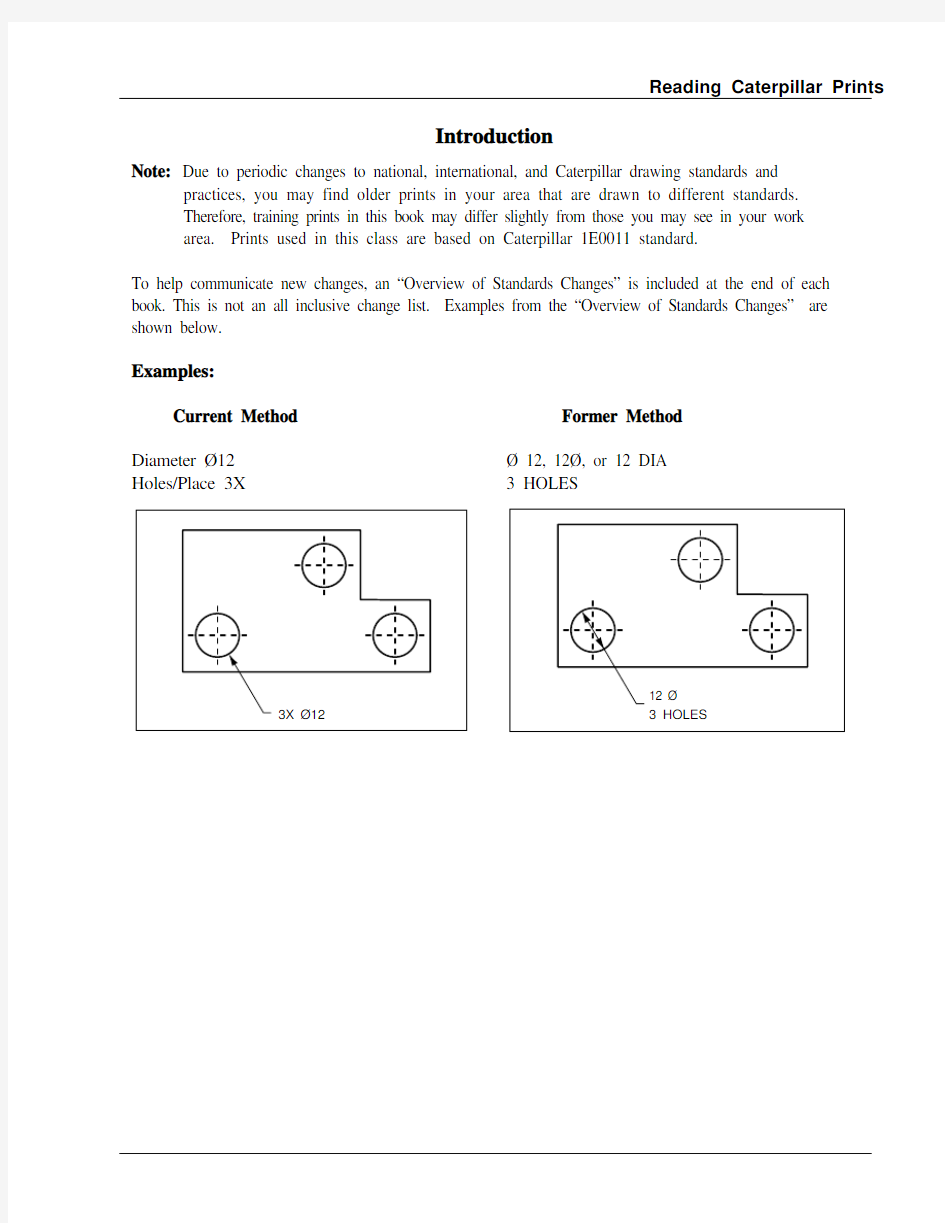
Example drawings in this book may be incomplete. This book is intended for training purposes only.
All 1E Specifications located throughout this book are specific to Caterpillar, Inc.
Caterpillar uses 1E Specifications:
? To protect confidentiality and intellectual property concerns
? For standardization
? To reduce the amount of data depicted on engineering drawings (clarity)
? 2009 Caterpillar Inc.
Reading Caterpillar Prints
Table of Contents Lesson 1
Introduction to Print Reading Lesson 1 Activity
1-1 A 1-1
Lesson 2
Multiview Drawings Lesson 2 Activity
2-1 A 2-1
Lesson 3
Isometric Drawings Lesson 3 Activity
3-1 A 3-1
Lesson 4
Types of Lines Used on Prints Lesson 4 Activity
4-1 A 4-1
Lesson 5
Representing Surfaces on Prints Lesson 5 Activity
5-1 A 5-1
Lesson 6
Auxiliary Views Lesson 6 Activity
6-1 A 6-1
Lesson 7
Section Views Lesson 7 Activity
7-1 A 7-1
Lesson 8
Dimensioning Methods Lesson 8 Activity
8-1 A 8-1
Lesson 9
External Feature Dimensions and Tolerances Lesson 9 Activity
9-1 A 9-1
Lesson 10
Internal Feature Dimensions and Tolerances Lesson 10 Activity
10-1 A 10-1
Overview of Standards Changes Overview 1-1 Answer Key Key 1-1
Reading Caterpillar Prints Introduction to Print Reading
Lesson 1
Introduction to Print Reading
Objectives
1. You will be able to match lines representing surfaces and edges on an isometric drawing with
corresponding lines shown on a multiview drawing.
2. Given a Caterpillar print, you will be able to identify the following information:
a. Part name.
b. Part number.
c. Names of drawing views.
d. Part height.
e. Part depth.
f. Part width.
g. Unit of measure.
h. Title Block.
i. Data Block.
j. Drawing Version (Primary and Secondary).
k. Design Control.
l. Drawing Class.
m. Sheet Number.
n. Border Coordinate.
Introduction to Print Reading Reading Caterpillar Prints The term “BLUEPRINT” is an old generic term used for any copy of an engineering drawing. It was called a blueprint because the copying process of the original drawing produced a blue colored copy. That is not true today since most copies are black and white. Industry now uses the term “PRINT” to refer to all types of engineering drawings.
The following page displays a typical Caterpillar print.
It has two major parts:
BODY OF THE PRINT: Includes the drawing, notes, and dimensions that describe the part. Around the body of the drawing is a Border Coordinate– used as a coordinate locating system (similar to that used on a map). REF: The pictorial view on the following page is located in area 01C1.
TITLE BLOCK: Contains the Part Name, Part Number, Unit of Measure, Engineering Change Number and other information.
DATA BLOCK: Contains Design Control, Number of Sheets, Version Type and 1E Specifications.
Most Caterpillar prints today are drawn using the metric system. These prints will have
“METRIC” printed in the upper right-hand corner of the print and will be designated as a metric drawing in the data block by the statement “UNLESS OTHERWISE SPECIFIED DIMENSIONS
ARE IN mm.” The abbreviation “mm” means millimeter.
Non-metric drawings are displayed in inches.
PART NUMBERS: Three primary formats are used:
? Six positions 9T-2392 (Format: NA-NNNN)
? Six or seven positions numeric 136-9418 (Format: NN-NNNN or NNN-NNNN)
? Seven position alpha-numeric 10R-3576 (Format: NNR-NNNN)
Note: Prints used in this course will have 6 positions (TP0001)
“TP” = Training Print.
PICTORIAL VIEW: In the upper right-hand corner of the body of the print you see an isometric drawing of the part. This is called a “pictorial view.” It is an optional feature used primarily to help visualize complex drawings.
Reading Caterpillar Prints
Introduction to Print Reading
Introduction to Print Reading Reading Caterpillar Prints Prints were drawn manually in the past. Today we use computer based systems for drawing, storing and generating prints. The system we use to store and generate prints is called RASTAR.
Introduction to Print Reading Reading Caterpillar Prints
Reading Caterpillar Prints Introduction to Print Reading
Introduction to Print Reading Reading Caterpillar Prints Print TP0002 is a multiview drawing of a rectangular block. It has front, top, and right-side views. Notice the positioning of the views on the drawing. This is the standard arrangement for principle views (when three views are needed).
? Front view – Lower left-hand corner of print.
? Top view – Located directly above and projected from the front view.
? Right-side view – Located directly to the right and projected from the front view.
Each view shows different features/characteristics of the part:
? Front view – Height and width
Cylindrical part (shaft/bar) – Length and diameter
? Top view – Width and depth
Cylindrical part – Length and diameter (if view is needed)
? Right-side view – Depth and height
Cylindrical part – Diameter
Reading Caterpillar Prints Introduction to Print Reading
Introduction to Print Reading Reading Caterpillar Prints
Reading Caterpillar Prints Introduction to Print Reading - Activity
Test Your Understanding of Lesson 1
Use Caterpillar print TP0003 to answer the questions below:
1. What is the name of the part? _____________________________________________
2. What is the part number? ________________________________________________
3. What is the unit of measure for this part? ____________________________________
4. Name the three views used to represent the part. ______________________________
_____________________________________________________________________
5. What is the overall height of the part? ____________________________________________
6. What is the width of the part? _____________________________________________
7. What does the dimension at 01D3 represent on the part? __________________________
8. Which views show height? ____________________________________________
9. Which views show width? ____________________________________________
10. Which views show depth? _____________________________________________
11. What is the isometric drawing in the upper right-hand corner called? ______________
12. Will you see pictorial views on all prints? ___________________________________
Introduction to Print Reading - Activity Reading Caterpillar Prints
Reading Caterpillar Prints Introduction to Print Reading - Activity Questions 13 - 19
Find the numbered surfaces in the multiview drawings that correspond to the lettered surfaces in the isometric drawing. Complete the chart below, by writing the corresponding number in the column headed by the view, where the surface is seen in the multiview drawing.
Example: The surface numbered “5”, seen in the front view of the multiview drawing, corresponds to the surface lettered “A” in the isometric drawing. In the chart, the number “5” has been written on the same line as the letter “A”, and in the column headed by “Front.”
Isometric Drawing Multiview Drawing
Introduction to Print Reading - Activity Reading Caterpillar Prints Questions 20 - 30
Complete the chart by matching the numbers of the surfaces shown in the multiview drawing with the letter of the corresponding surface shown in the isometric drawing.
Note: In the multiview drawing, the same surface has a different number in each view. See the example for surface “A” in chart.
Multiview Drawing
Isometric Drawing
Reading Caterpillar Prints Multiview Drawings
Lesson 2
Multiview Drawings
Objectives
1. Given an isometric drawing and a drawing grid, you will be able to identify and sketch the
following views:
a. Front.
b. Top.
c. Right side.
2. You will be able to identify and apply the concept of hidden lines.
Multiview Drawings
Reading Caterpillar Prints
The RIGHT SIDE of the object can be projected onto the right side of the cube.
Right Side View Projection
We have seen how multiview drawings can be used to represent objects.Imagine the object inside a cube. The FRONT of the object can be projected onto the front of the cube.
Front View Projection
Reading Caterpillar Prints Multiview Drawings Top View Projection
The TOP of the object can be projected onto the top of the cube.
Bottom View Projection
The BOTTOM of the object can be projected onto the bottom of the cube. A dashed line represents the edge hidden, when viewing the object from the bottom.